

Page 1
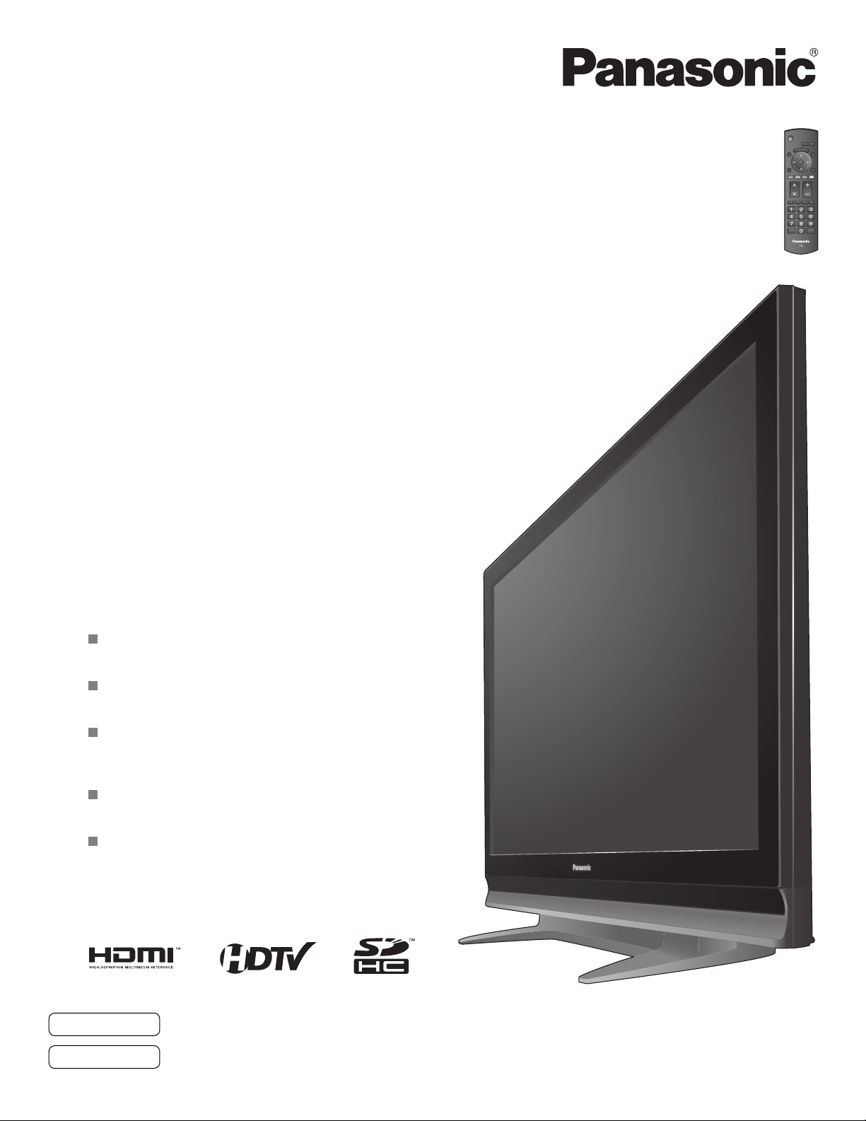
High Definition Plasma Television
Televisor de plasma de alta definición
Quick Start Guide
(See page 6)
Guía de inicio rápido
(vea la página 6)
Operating Instructions
Manual de instrucciones
Model No.
Número de modelo
TH-58PE75U
For assistance (U.S.A.), please call:
1-888-VIEW-PTV (843-9788)
or visit us at www.panasonic.com/contactinfo
For assistance (Puerto Rico), please call:
787-750-4300
or visit us at www.panasonic.com
For assistance (Canada), please call:
1-800-561-5505
or visit us at www.panasonic.ca
Para solicitar ayuda (EE.UU.), llame al:
1-888-VIEW-PTV (843-9788)
ó visítenos en www.panasonic.com/contactinfo
Para solicitar ayuda (Puerto Rico), llame al:
787-750-4300
ó visítenos en www.panasonic.com
English
Español
Please read these instructions before operating your set and retain them for future reference.
The images shown in this manual are for illustrative purposes only.
Lea estas instrucciones antes de utilizar su televisor y guárdelas para consultarlas en el futuro.
Las imágenes mostradas en este manual tienen solamente fines ilustrativos.
TQB2AA0752
Page 2
Turn your own living room into a movie theater!
Experience an amazing level of multimedia excitement
2
SDHC Logo is a trademark.
HDMI, the HDMI logo and High-Definition Multimedia Interface are
trademarks or registered trademarks of HDMI Licensing LLC.
GalleryPlayer and the
GalleryPlayer Logo are
trademarks of GalleryPlayer, Inc.
EZ Sync™
EZ Sync™ is a trademark of Matsushita Electric Industrial Co., Ltd.
HDAVI Control™
HDAVI Control™ is a trademark of Matsushita Electric Industrial Co., Ltd.
Page 3
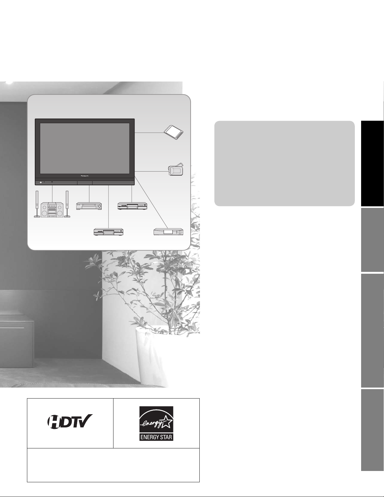
Enjoy rich multimedia
SD memory card
Camcorder
Contents
Please read before using the unit
Safety Precautions ·······································4
•
Notes ····························································5
•
Quick Start Guide
Accessories/Optional Accessory
•
To Prevent TV from Falling Over
•
Before Connection ······················ 10
•
Basic Connection ·························11
•
Identifying Controls ····················17
•
First Time Setup ··························18
··· 6
··· 8
•
Amplifier
Home theater
system
VCR DVD player
DVD recorder Set Top Box
Enjoy your TV!
Basic Features
Watching TV ···············································20
•
Viewing from SD Card ·······························22
•
Watching Videos and DVDs ·······················24
•
Advanced Features
How to Use Menu Functions
•
(picture, sound quality, etc.) ·······················26
EZ SyncTM “HDAVI ControlTM” ·····················30
•
Lock ···························································32
•
Editing and Setting Channels ····················34
•
Input Labels/Monitor Out/Closed Caption
•
Using Timer ················································38
•
Recommended A V Connections ················40
•
Viewing Advanced FAQs, etc.Quick Start Guide
······36
Manufactured under license from Dolby Laboratories.
DOLBY and the double-D symbol are
trademarks of Dolby Laboratories.
FAQs, etc.
Ratings List for Lock ··································42
•
Technical Information ·································43
•
Maintenance ··············································46
•
Specifications ·············································47
•
FAQ ····························································48
•
Limited Warranty (for U.S.A.) ·····················50
•
Customer Services Directory (for U. S. A.)
•
Limited Warranty (for Canada) ···················52
•
····51
3
Page 4
Safety Precautions
The lightning flash with
arrowhead within a triangle
CAUTION
RISK OF ELECTRIC SHOCK
DO NOT OPEN
WARNING: To reduce the risk of electric shock, do not remove cover or back.
No user-serviceable parts inside. Refer servicing to qualified service personnel.
WARNING: To reduce the risk of fire or electric shock, do not expose this apparatus to rain or moisture.
Do not place liquid containers (flower vase, cups, cosmetics, etc.) above the set
(including on shelves above, etc.).
Important Safety Instructions
1) Read these instructions.
2) Keep these instructions.
3) Heed all warnings.
4) Follow all instructions.
5) Do not use this apparatus near water.
6) Clean only with dry cloth.
7) Do not block any ventilation openings. Install in accordance
with the manufacturer’s instructions.
8) Do not install near any heat sources such as radiators, heat
registers, stoves, or other apparatus (including amplifiers)
that produce heat.
9) Do not defeat the safety purpose of the polarized or
grounding-type plug. A polarized plug has two blades with
one wider than the other. A grounding type plug has two
blades and a third grounding prong. The wide blade or the
third prong are provided for your safety. If the provided
plug does not fit into your outlet, consult an electrician for
replacement of the obsolete outlet.
10) Protect the power cord from being walked on or pinched
particularly at plugs, convenience receptacles, and the
point where they exit from the apparatus.
11) Only use attachments / accessories specified by the
manufacturer.
12) Use only with the cart, stand, tripod,
bracket, or table specified by the
manufacturer, or sold with the
apparatus. When a cart is used,
use caution when moving the cart /
apparatus combination to avoid injury
from tip-over.
13) Unplug this apparatus during lightning
storms or when unused for long periods of time.
14) Refer all servicing to qualified service personnel. Servicing
is required when the apparatus has been damaged in any
way, such as power-supply cord or plug is damaged, liquid
has been spilled or objects have fallen into the apparatus,
the apparatus has been exposed to rain or moisture, does
not operate normally, or has been dropped.
15) To prevent electric shock, ensure the grounding pin on the
AC cord power plug is securely connected.
is intended to tell the user
that parts inside the product
are a risk of electric shock to
persons.
The exclamation point within
a triangle is intended to
tell the user that important
operating and servicing
instructions are in the papers
with the appliance.
4
FCC STATEMENT
This equipment has been tested and found to comply with the limits for an Other Class B digital device, pursuant to Part 15 of the
FCC Rules. These limits are designed to provide reasonable protection against harmful interference in a residential installation.
This equipment generates, uses and can radiate radio frequency energy and, if not installed and used in accordance with the
instructions, may cause harmful interference to radio communications. However, there is no guarantee that interference will not
occur in a particular installation. If this equipment does cause harmful interference to radio or television reception, which can be
determined by turning the equipment off and on, the user is encouraged to try to correct the interference by one or more of the
following measures:
• Reorient or relocate the receiving antenna.
• Increase the separation between the equipment and receiver.
• Connect the equipment into an outlet on a circuit different from that to which the receiver is connected.
• Consult the Panasonic Service Center or an experienced radio/TV technician for help.
FCC Caution:
To assure continued compliance, use only shielded interface cables when connecting TV to peripheral devices.
Any changes or modifications not expressly approved by responsible party may cause harmful interference and could
void the user’s authority to operate this device.
Responsible Party: Panasonic Corporation of North America
One Panasonic Way, Secaucus, NJ 07094
Contact Source: Panasonic Consumer Electronics Company
1-888-VIEW-PTV (843-9788)
email: [email protected]
CANADIAN NOTICE:
For Model TH-58PE75U
This Class B digital apparatus complies with Canadian ICES-003.
Page 5
WARNING/CAUTION
If problems occur during use
WARNING
SMALL PARTS CAN PRESENT CHOKING HAZARD IF
ACCIDENTALLY SWALLOWED.
KEEP SMALL PARTS AWAY FROM YOUNG CHILDREN.
DISCARD UNNEEDED SMALL PARTS AND OTHER OBJECTS,
INCLUDING P ACKAGING MATERIALS AND PLASTIC BAGS/SHEETS
TO PREVENT THEM FROM BEING PLAYED WITH BY YOUNG
CHILDREN, CREATING THE POTENTIAL RISK OF SUFFOCATION.
Set up
■
Do not place the Plasma TV on sloped or unstable surfaces.
The Plasma TV may fall off or tip over.
Do not place any objects on top of the Plasma TV.
If water spills onto the Plasma TV or foreign objects get
inside it, a short-circuit may occur which could result in fire
or electric shock. If any foreign objects get inside the Plasma
TV, please consult an Authorized Service Center.
This Plasma TV is for use only with the following optional
accessories. Use with any other type of optional accessories may
cause instability which could result in the possibility of injury.
(All of the following accessories are manufactured by
Matsushita Electric Industrial Co., Ltd.)
• Wall-hanging bracket (Vertical) TY-WK42PV3U
Always be sure to ask a qualified technician to carry out set-up.
Two or more people are required to install and remove the
television. If two people are not present, the television may
be dropped, and personal injury may result.
Transport only in upright position!
Transporting the unit with its display panel facing upright or
downward may cause damage to the internal circuitry.
AC Power Supply Cord
■
The Plasma TV is designed to operate on 120 V AC, 60 Hz.
Securely insert the power cord plug as far as it will go.
If the plug is not fully inserted, heat may be generated which
could cause fire. If the plug is damaged or the wall socket
plate is loose, they should not be used.
The included power cord is for use with this unit only.
Do not use any power cord other than that provided with this TV.
Doing so may cause fire or electric shocks.
Do not handle the power cord plug with wet hands.
Doing so may cause electric shocks.
Do not do anything that might damage the power cable. When
disconnecting the power cable, hold the plug, not the cable.
Do not make any modifications to, place heavy objects on,
place near hot objects, heat, bend, twist or forcefully pull the
power cable. Doing so may cause damage to the power cable
which can cause fire or electric shock. If damage to the cable
is suspected, have it repaired at an Authorized Service Center.
■
If a problem occurs (such as no picture or no sound), or if
smoke or an abnormal odor is detected from the Plasma
TV, unplug the power cord immediately.
Continued use of the TV under these conditions might cause
fire or permanent damage to the unit. Have the TV evaluated
at an Authorized Service Center. Servicing of the TV by any
unauthorized personnel is strongly discouraged due to its
high voltage dangerous nature.
If water or foreign objects get inside the Plasma TV, if the
Plasma TV is dropped, or if the cabinet becomes damaged,
disconnect the power cord plug immediately.
A short may occur, which could cause fire. Contact an
Authorized Service Center for any repairs that need to be
made.
Do not cover the ventilation holes.
Doing so may cause the Plasma TV to overheat, which can
cause fire or damage to the Plasma TV.
If using the pedestal, leave a space of 3 15/16 ” (10 cm) or
more at the top, left and right, 1 49/64 ” (4.5 cm) or more at
the bottom, and 2 3/4 ” (7 cm) or more at the rear.
When using the Plasma TV
■
Be sure to disconnect all cables before moving the Plasma
TV.
Moving the TV with its cables attached might damage the
cables which, in turn, can cause fire or electric shock.
Disconnect the power plug from the wall outlet as a safety
precaution before carrying out any cleaning.
Electric shocks can result if this is not done.
Clean the power cable regularly to prevent it from
becoming dusty.
Built-up dust on the power cord plug can increase humidity
which might damage the insulation and cause fire. Unplug the
cord from the wall outlet and clean it with a dry cloth.
This Plasma TV radiates infrared rays; therefore, it may
affect other infrared communication equipment.
Install your infrared sensor in a place away from direct or
reflected light from your Plasma TV.
Do not climb up onto the television or use it as a step.
(Young children should be made particularly aware of this
caution.)
If the unit falls over or becomes damaged through misuse,
injury may result.
The TV will still consume some power as long as the power
cord is inserted into the wall outlet.
CAUTION
Notes
Do not display a still picture for a long time
■
This causes the image to remain on the plasma screen
(“Image retention”). This is not considered a malfunction and is
not covered by the warranty.
Typical still images
Channel number and other logos
Image displayed in 4:3 mode
SD Card photo
Video game
Computer image
4 : 3
Setup
■
Do not place the unit where it’s exposed to sunlight or other
bright light (including reflections).
Use of some types of fluorescent lighting may reduce the
remote control’s transmission range.
12
To prevent “Image retention”,
the screen saver is
automatically activated after
a few minutes if no signals
are sent or no operations are
performed. (p. 49)
5
Page 6

Accessories/Optional Accessory
Check you have all the items shown.
Accessories
Remote Control
Transmitter
N2QAYB000103
•
AC cord
Operating Instructions
Quick Setup Guide
(For viewing HD programming)
Remote Control
Transmitter
AA Battery
•
Pedestal
TBL2AX00191
•
Antenna Adapter
F-Type for 5C-2V
(2)
Product Registration Card (U.S.A.)
Customer Care Plan Card (U.S.A.)
Installing the remote’s batteries
•
How to assemble (p.7)
Cable clamper (2)Batteries for the
1
Open
Hook
Optional Accessory
Wall-hanging bracket
(vertical)
TY-WK42PV3U
•
Caution
2
Close
Note the correct polarity
(+ or -).
Note
In order to maintain the TV’s performance and safety, be absolutely sure
•
to ask your dealer or a licensed contractor to secure the wall-hanging
brackets.
Carefully read the instructions accompanying the plasma TV stand or
•
pedestal, and be absolutely sure to take steps to prevent the TV from
tipping over.
Handle the TV carefully during installation since subjecting it to impact
•
or other forces may cause its paneling to crack.
Incorrect installation may cause battery
•
leakage and corrosion, resulting in
damage to the remote control.
Do not mix old and new batteries.
•
Do not mix different battery types (such as
•
alkaline and manganese batteries).
Do not use rechargeable (Ni-Cd) batteries.
•
Do not burn or break batteries.
•
6
Page 7
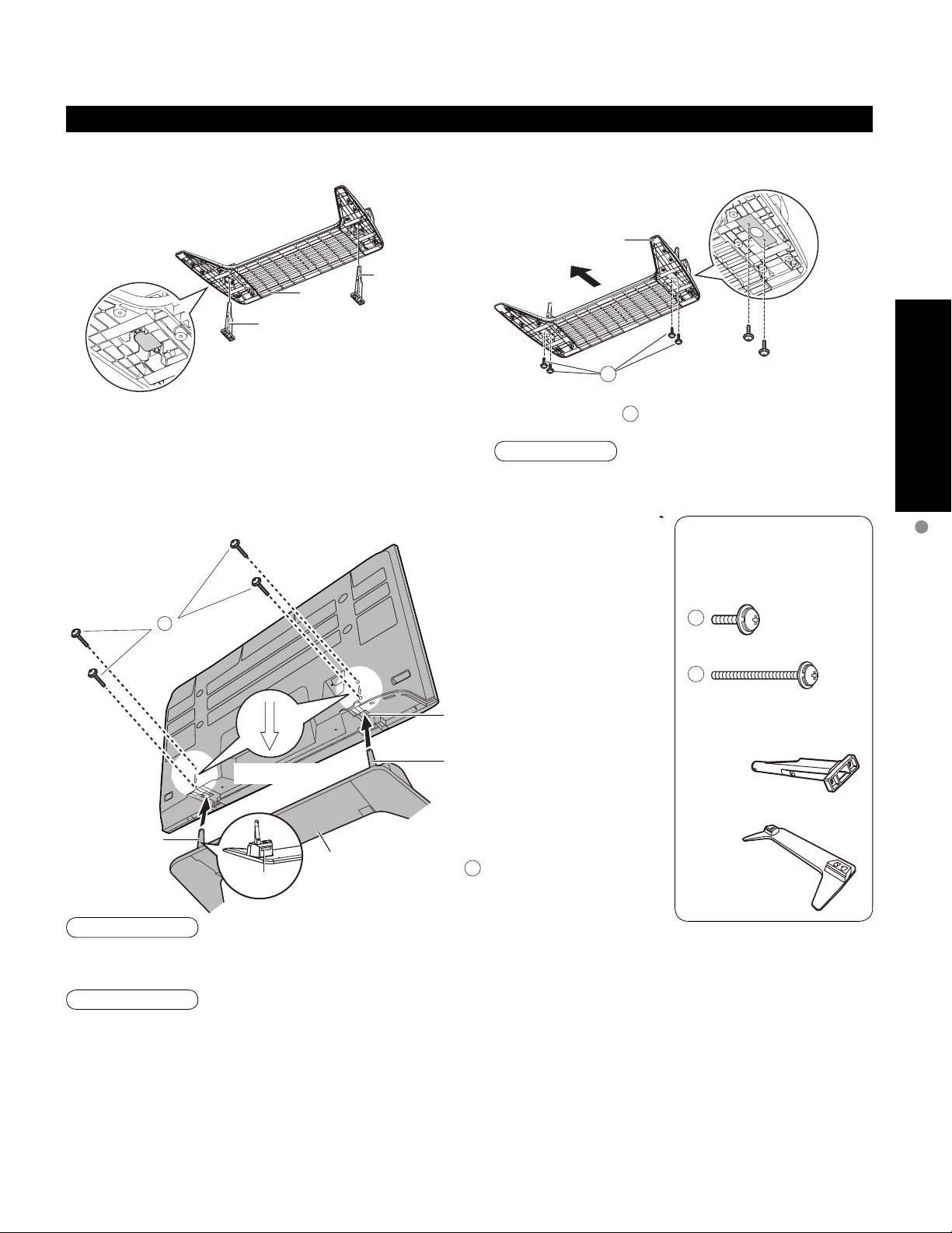
Attaching the pedestal to TV
Assembling the pedestal
■
Installing the poles Securing the poles
Base
Front
Pole
Base
Pole
A
Quick Start Guide
Insert the poles into the left and right holes in the
underside of the base so that they fit securely as
shown in the illustration above.
Set-up
■
Carry out work on a horizontal and level surface.
•
B
Arrow mark
Pole
Base
Label
Use the assembly A screws to secure the poles firmly
to the bottom of the base.
Note
Forcing the assembly screws the wrong way will strip
the threads.
Bottom view
Rear side
Hole for pedestal
installation
Pole
Fix securely with assembly
•
screws B.
(Total 4 screws)
Accessories
Accessories/Optional Accessory
Assembly screw
(4 of each)
A
M5 x 20
B
M5 x 30
Pole (2)
Base (1)
Warning
Do not disassemble or modify the pedestal.
Otherwise the TV may fall over and become damaged, and personal injury may result.
•
Caution
Do not use any television or displays other than those given in these Operating Instructions.
Otherwise the TV may fall over and become damaged, and personal injury may result.
•
Do not use the pedestal if it becomes warped or physically damaged.
If you use the pedestal while it is physically damaged, personal injury may result. Contact your nearest Panasonic
•
Dealer immediately.
During set-up, make sure that all screws are securely tightened.
If sufficient care is not taken to ensure screws are properly tightened during assembly, the pedestal will not be strong enough to
•
support the TV, and it might fall over and become damaged, and personal injury may result.
Use the accessory fall-prevention brackets to secure the TV.
If the TV is knocked or children climb onto the pedestal with the TV installed, the TV may fall over and personal
•
injury may result.
7
Page 8
To Prevent TV from Falling Over
The Plasma TV could fall over during an earthquake, etc.
We recommend that measures are taken to prevent the Plasma TV from falling over in such an event.
The information in this section is designed to reduce the risk of injuries caused by the Plasma TV falling over
•
during an earthquake, etc.
However, no measure can guarantee protection against all earthquakes.
The precautions in this section are recommendations for providing more secure installation of your plasma TV if
•
you live in an earthquake prone area.
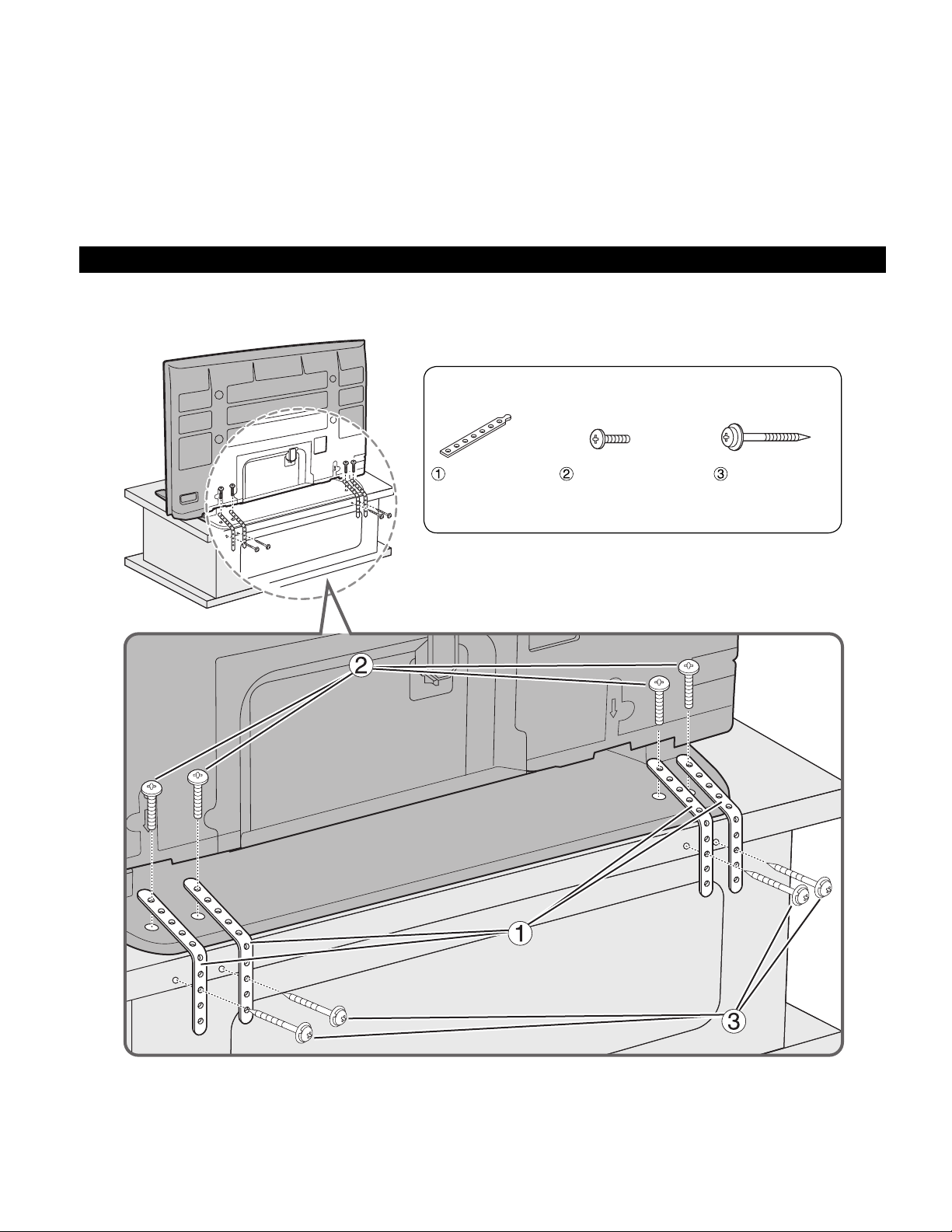
Securing to a base
Fix pedestal and base together with band.
•
Accessories
Band (4) Screw (4)
• Nominal diameter
4 mm x 12
Wood screw (4)
8
Page 9
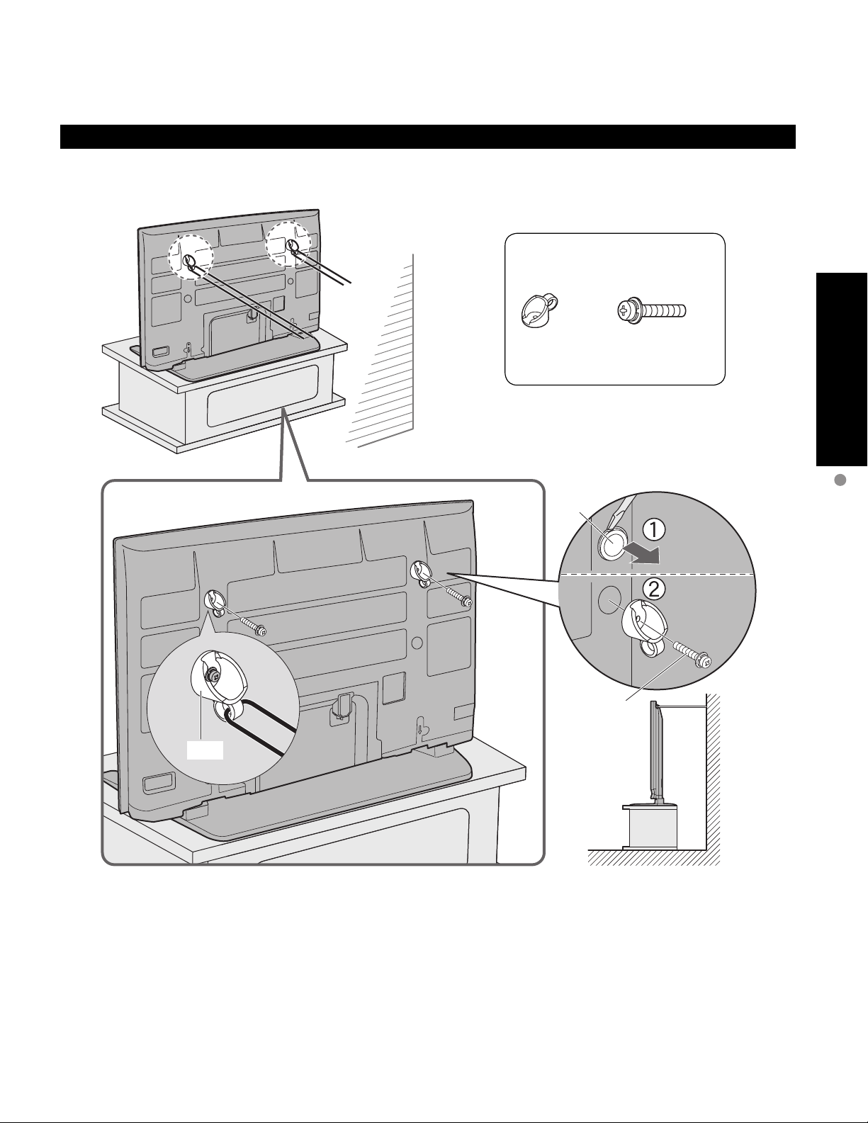
Securing to a wall
Fix to wall or post with strong commercial wire or chain.
•
Accessories
Quick Start Guide
Hook
Hook (2) Hook securing screw (2)
• M8 x 35
Remove
screw
Hook securing
screw
To Prevent TV from Falling Over
9
Page 10
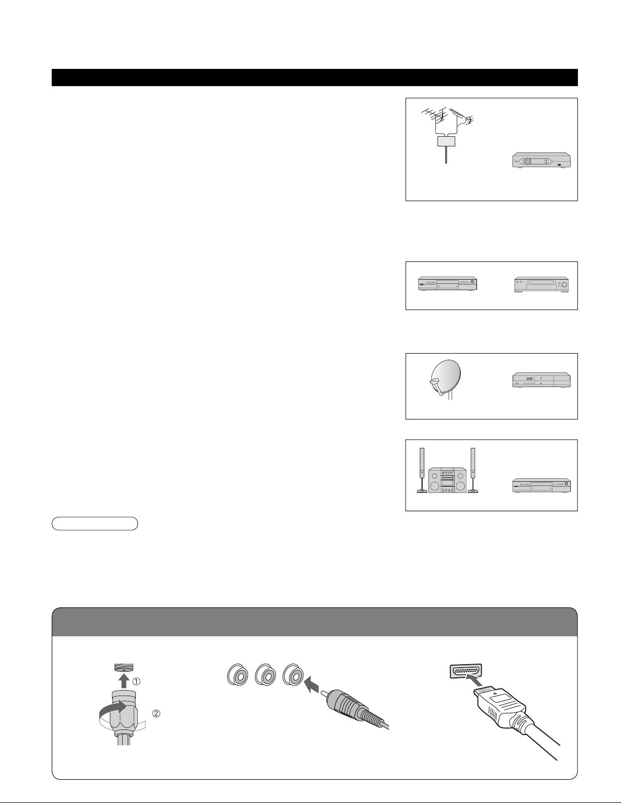
Reference of connection
Before Connection
Connected Equipment Introduction (Signal source)
Watching TV
■
VHF/UHF Antenna
•
NTSC (National Television System Committee):
•
Conventional broadcasting
ATSC (Advanced Television Systems Committee):
•
Digital TV Standards include digital high-definition television (HDTV),
standard-definition television (SDTV), data broadcasting, multi-channel
surround-sound audio and interactive television.
Cable Box/Cable
•
• You need to subscribe to a cable TV service to enjoy viewing their
programming.
You can enjoy high-definition programming by subscribing to a high-definition cable box. The connection can be
•
done with the use of HDMI or Component Video cable.
Recording/playing back with DVD recorder or VCR
■
DVD Recorder
•
This source has higher resolution through interlace or progressive signal.
Connection can be done with the use of Component Video or HDMI cable.
VCR
•
Connection can be done with the use of an RF cable and Composite Video/S Video cable.
VHF/UHF Antenna Cable Box/
DVD Recorder
or
Cable
or
VCR
Watching Satellite
■
You can enjoy high-definition programming by subscribing to
•
high-definition satellite source. Connection can be done with the use of
HDMI or Component Video cable.
Satellite Antenna
Enjoying Home theater and DVD recorder with
■
HDMI connection
Home theater and DVD Recorder
•
HDMI connection enables you to enjoy higher quality audio and video with
a single cable.
Note
If your Panasonic DVD Recorder is compatible with EZ Sync (HDAVI control 2), you can operate your Panasonic
•
DVD Recorder with this TV’s remote control (p. 25 EZ SyncTM).
All cables and external equipment shown in this book are not supplied with the TV.
•
For the details of the external equipment’s connections, please refer to the operating manuals for the equipment.
•
Antenna terminal
■
Pin terminals
■
HDMI terminal
■
Satellite
Receiver
DVD RecorderHome Theater
10
Firmly tighten by hand.
•
greenbluered
green
Match colors of plugs and terminals.
•
Insert firmly.
•
Insert firmly.
•
Page 11
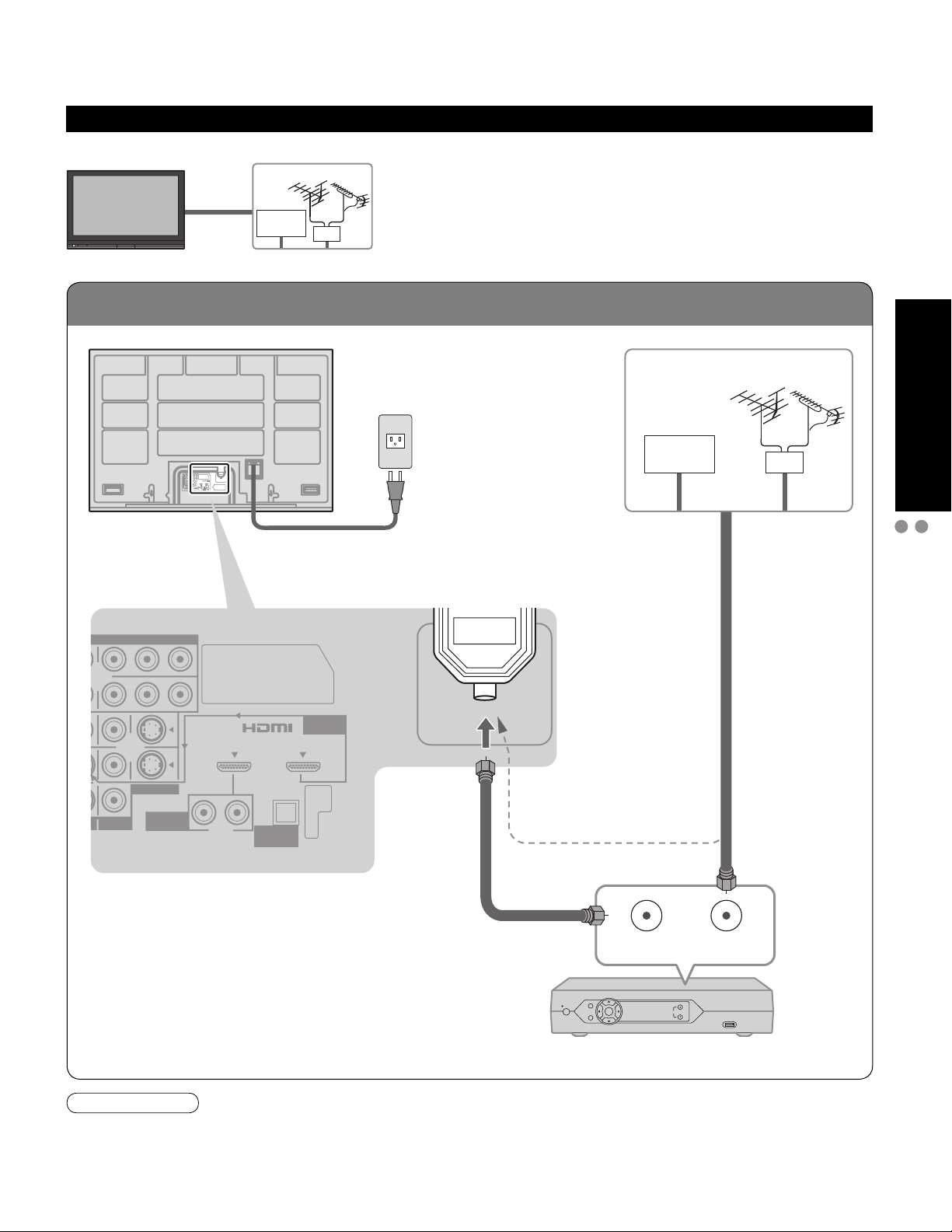
To connect antenna terminals
Basic Connection
Example 1
TV
Back of the TV
Connecting Antenna (To watch TV)
VHF/UHF Antenna
Cable TV
AC 120 V
60 Hz
ANTENNA
Cable In
AC Cord
(Connect after all the
other connections.)
Cable TV
VHF/UHF Antenna
or
Quick Start Guide
Basic Connection (Antenna + TV)
Before Connection
VIDEO
PR PB Y
PR PB Y
AV IN 1 AV IN 2
S VIDEO
VIDEO
If using Cable Box
•
•
HDMI 1
RL
AUDIO IN
Set the TV channel to CH3 or CH4.
DIGITAL
AUDIO OUT
HDMI 2
AUDIO IN
Antenna
terminal
ANTENNA
Cable In
(If no Cable Box)
or
ANT OUT ANT IN
Cable Box
Note
When disconnecting the power cord, be absolutely sure to disconnect the power cord plug from the wall outlet first.
•
For additional assistance, visit us at: www.panasonic.com
•
www.panasonic.ca
11
Page 12
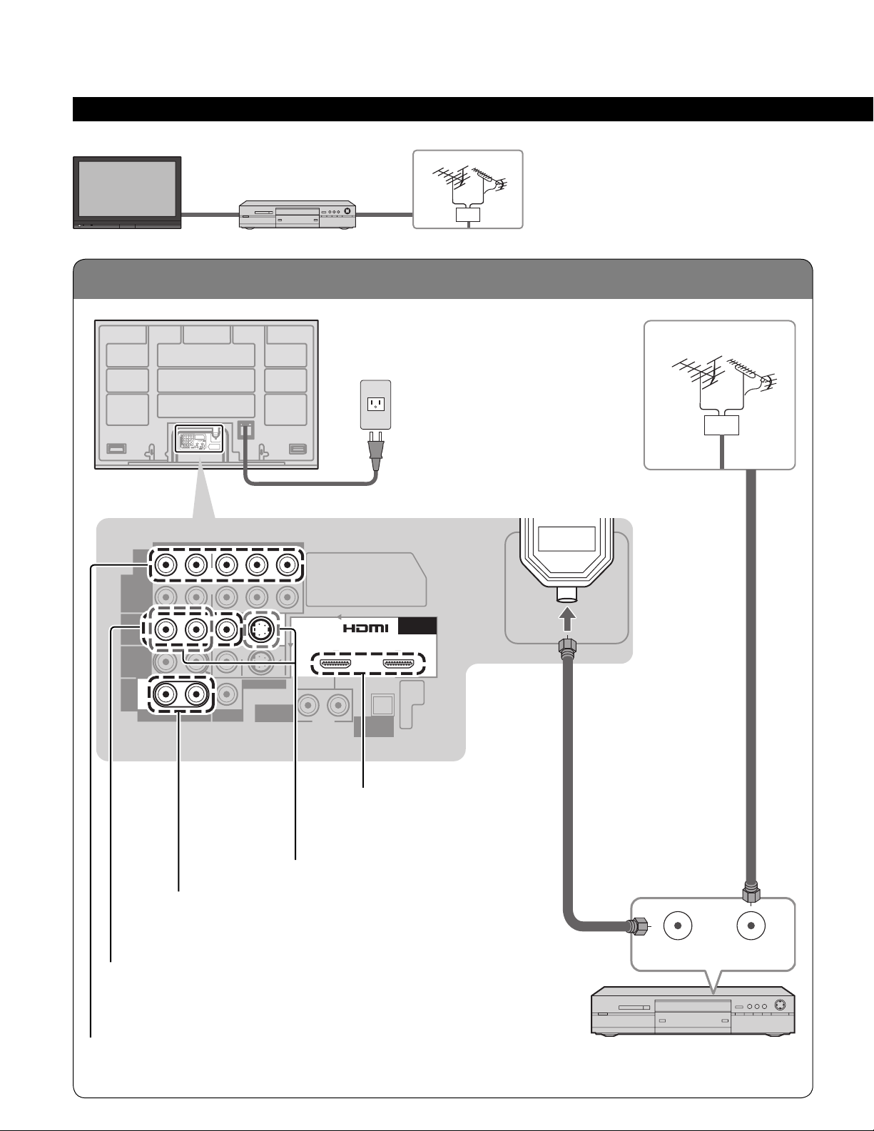
To connect antenna terminals
Basic Connection (Continued)
Example 2
TV
Back of the TV
Connecting DVD recorder (VCR) (To record/playback)
VHF/UHF Antenna
AV Equipment
(e.g. DVD Recorder or VCR)
AC 120 V
60 Hz
ANTENNA
Cable In
AC Cord
Antenna
terminal
VHF/UHF Antenna
AUDIO VIDEO
R
COMPONENT
VIDEO
INPUT
R
INPUT 1
R
INPUT 2
R
TO
PROG
AUDIO
OUT
AMP
R
AUDIO
L
L
L
L
L
PR PB Y
PR PB Y
S VIDEO
VIDEO
To use PROG OUT terminals
(p. 40, 41)
AV IN 1 AV IN 2
HDMI 1
RL
AUDIO IN
DIGITAL
AUDIO OUT
To use HDMI
terminals
(next page)
To use S VIDEO terminals
(next page)
HDMI 2
AUDIO IN
ANTENNA
Cable In
12
To use COMPOSITE terminals
(next page)
To use COMPONENT terminals
(next page)
ANT OUT ANT IN
AV Equipment
(e.g. DVD Recorder or VCR)
(with TV tuner)
Page 13
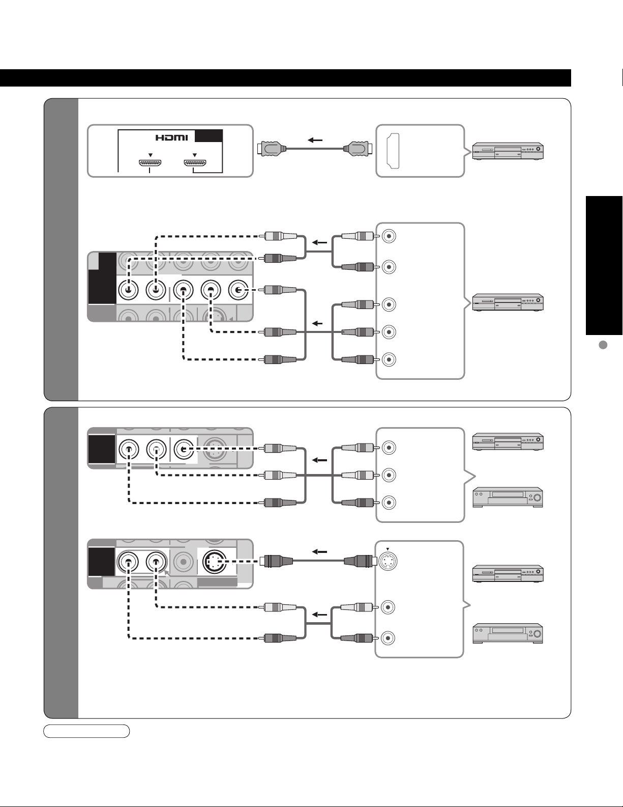
High-Definition
Standard-Definition
COMPONENT
VIDEO
INPUT
R
PR PB Y
P
R PB Y
R
L
L
INPUT 1
PR PB Y
R
R
L
L
TO
INPUT 2
S VIDEO
R
R
L
L
To use HDMI terminals
■
HDMI 2
AV IN 1 AV IN 2
Connecting to HDMI terminals will enable you to enjoy high-definition digital images and high-quality
•
sound.
To use COMPONENT terminals
■
Recorders may also be connected to COMPOSITE or S VIDEO terminals. (see below)
•
AUDIO IN
white
red
green
blue
red
white
red
green
blue
red
white
red
green
blue
red
L
R
Y
P
B
PR
HDMI
AV OUT
AUDIO
OUT
COMPONENT
VIDEO OUT
AV Equipment
e.g. DVD Recorder
AV Equipment
e.g. DVD Recorder
Quick Start Guide
Basic Connection
(TV + DVD Recorder or VCR)
To use COMPOSITE terminals
■
To use S VIDEO terminals
■
The S Video input will override the composite
•
video signal when S Video cable is connected.
Connect either S Video or Video cable.
yellow
white
red
white
red
AV Equipment
yellow
Connecting to S VIDEO terminals will enable
•
you to enjoy greater picture quality than using
Composite terminals.
white
red
white
red
yellow
white
red
white
red
L
COMPOSITE
OUT
R
S VIDEO
OUT
L
AUDIO
R
OUT
e.g. DVD Recorder
or
e.g. VCR
AV Equipment
e.g. DVD Recorder
or
e.g. VCR
Note
Some programs contain a copyright protection signal to prevent recording.
•
When the copyright protection program is displayed, do not connect the other TV monitor through a VCR. Video signals fed
•
through VCRs may be affected by copyright protection systems and the picture will be distorted on the other TV monitor.
For the details of the external equipment’s connections, please refer to the operating manuals for the equipment.
•
13
Page 14
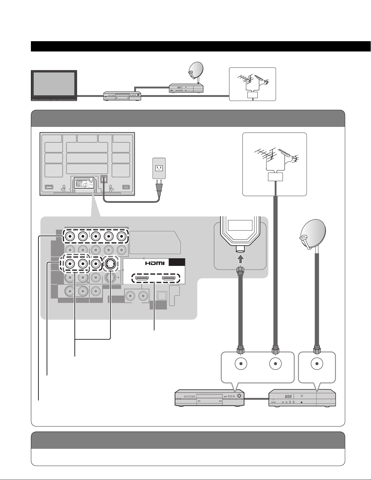
To connect antenna terminals
Connecting TV and DVD recorder (VCR)
Basic Connection (Continued)
Example 3
TV
Back of the TV
Connecting DVD recorder (VCR) and satellite receiver
DVD Recorder
or
VCR
Satellite
Receiver
AC 120 V
60 Hz
VHF/UHF Antenna
VHF/UHF Antenna
ANTENNA
Cable In
AC Cord
Antenna
terminal
AUDIO VIDEO
R
COMPONENT
VIDEO
INPUT
R
INPUT 1
R
INPUT 2
R
TO
PROG
AUDIO
OUT
AMP
R
AUDIO
L
L
L
L
L
PR PB Y
PR PB Y
S VIDEO
VIDEO
AUDIO IN
HDMI 1
To use S VIDEO terminals
(p. 13)
To use COMPOSITE terminals
(p. 13)
AV IN 1 AV IN 2
RL
DIGITAL
AUDIO OUT
To use HDMI
terminals
(p. 13)
HDMI 2
AUDIO IN
ANTENNA
Cable In
ANT OUT ANT IN
ANT IN
14
To use COMPONENT terminals
(p. 13)
Connect in the same way as on p. 13.
Satellite ReceiverDVD Recorder or VCR
(with TV tuner)
Page 15
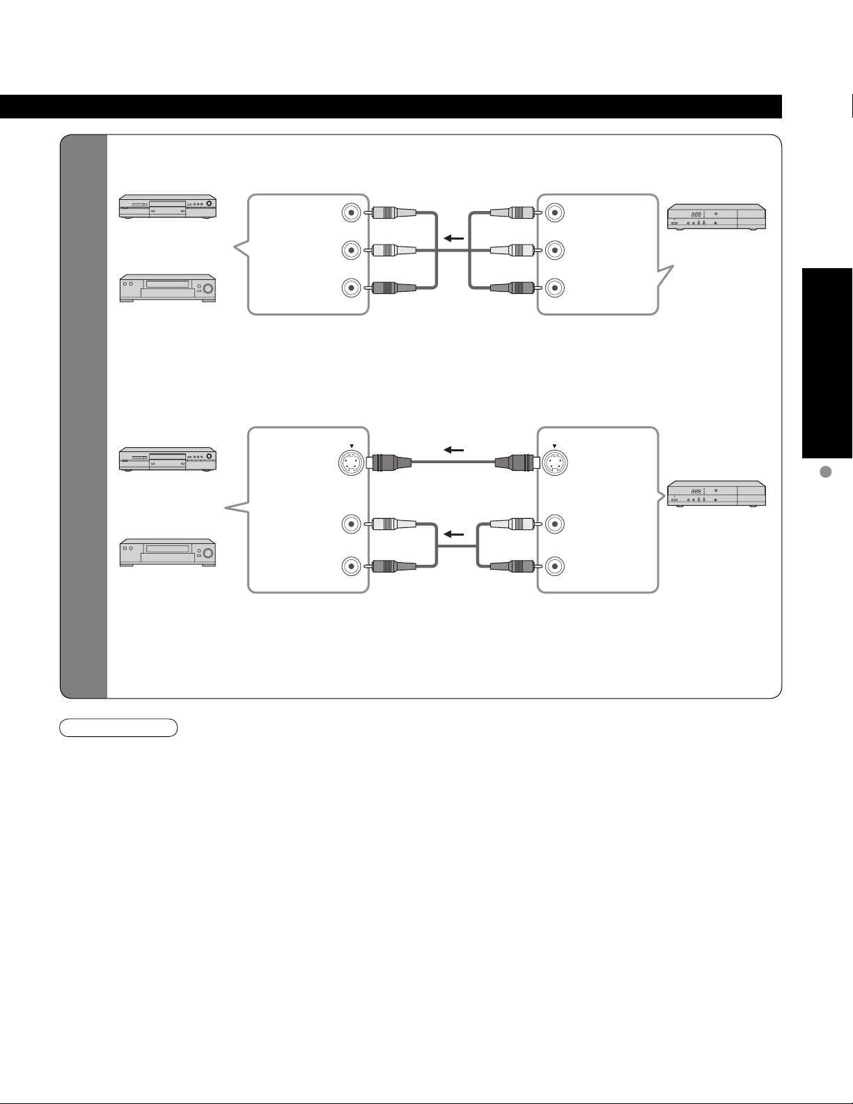
To Connect DVD Recorder/
VCR and satellite receiver
To use COMPOSITE terminals
■
DVD Recorder
or
VCR
To use S VIDEO terminals
■
DVD Recorder
or
VCR
The S Video input will override the composite video signal when S Video cable is connected. Connect
•
either S Video or Video cable.
Connecting to S VIDEO terminals will enable you to enjoy greater picture quality than using Composite
•
terminals.
COMPOSITE
IN
S VIDEO
IN
AUDIO
IN
yellow
L
white
R
red
L
white
R
red
yellow
white
red
white
red
yellow
white
red
white
red
yellow
white
red
white
red
L
COMPOSITE
OUT
R
S VIDEO
OUT
L
AUDIO
OUT
R
Satellite Receiver
Satellite Receiver
Quick Start Guide
Basic Connection
(TV + DVD Recorder or VCR + Satellite Receiver)
Note
For the details of the external equipment’s connections, please refer to the operating manuals for the equipment.
•
15
Page 16

To connect HDMI terminals
RL
HDMI 1
AUDIO IN
VIDEO
S VIDEO
PRPBY
Basic Connection (Continued)
Example 4
TV
Back of the TV
Home theater
(HDMI AV OUT)
Connecting Home Theater and DVD recorder
Home Theater
DVD Recorder
HDMI 2
or
DIGITAL
AUDIO OUT
AUDIO IN
DVD Recorder
AV IN 1 AV IN 2
Home theater
(DIGITAL AUDIO IN)
(When listening to TV audio) [ATSC only]
HDMI
AV OUT
DIGITAL
AUDIO IN
HDMI
AV IN
Home Theater
(AV amp)
HDMI
AV OUT
Note
It is recommended that you use Panasonic’s HDMI cable. (P. 30)
•
When Using the COMPONENT VIDEO OUT terminals or the S VIDEO OUT terminal, refer to p. 13 “To use COMPONENT
•
terminals” or “To use S VIDEO terminals”.
If you connect RAM theater or Player theater with HDMI cable, use audio cable instead of the optical digital audio cable.
•
(p. 41)
Cable Binding Instructions
Do not bundle the RF cable and AC cord together
•
(could cause distorted image).
Fix cables with Cable clamper as necessary.
•
When using the options, follow the option’s assembly
•
manual to fix cables.
AC cord
To fix
Push until
clicks
ANTENNA
Cable In
To release
Press catch
in and pull
away
16
To attach
Insert
hole
To bundle
To remove To loosen
Snaps
Keep pushing
both side
snaps
hooks
Set
knob
Keep pushing
the knob
Page 17

-
SUB
MENU
-
Identifying Controls
Switches TV/VIDEO
POWER
button
Power indicator (on: red, off: no light)
Note
The TV consumes a limited amount of power as long as the power cord is inserted into the wall outlet.
•
Switches TV to On or Standby
Displays Main Menu (p. 26)
Changes the input mode (p. 24)
Remote control sensor
Within about 23 feet (7 meters) in front of the TV set.
Selects channels in sequence
Volume up/down
Swing up the door at “PULL”.
EZ Sync menu (p. 25, 30-31)
Selects Audio Mode for TV viewing
(p. 20)
Exits menus
Quick Start Guide
Identifying Controls
Basic Connection (TV + Home Theater + DVD Recorder)
Displays Sub Menu (p. 20, 28)
Colored buttons
(used for various functions)
(for example p. 22, 35)
Channel up/down
Changes aspect ratio (p. 21)
Operates the Favorite channel list
function. (p. 21)
Switches to previously viewed channel
and input modes.
SUB
MENU
Selects/OK/Change
Returns to previous menu
Volume up/down
Displays or removes the channel
banner (p. 20)
Sound mute On/Off
Numeric keypad to select any
channel (p. 20) or press to enter
alphanumeric input in menus.
(p. 24, 25, 32, 34)
Direct channel access for DTV and
DBS (p. 20)
17
Page 18
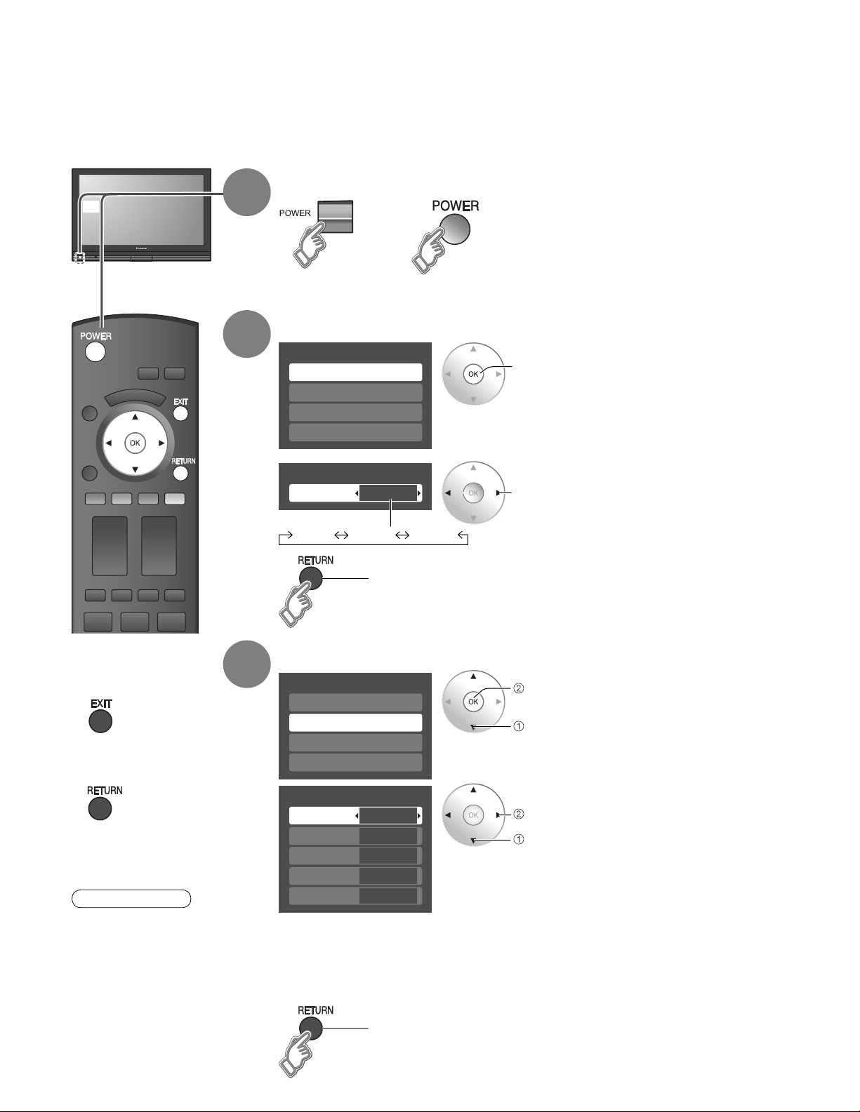
First Time Setup
“First time setup” is displayed only when the TV is turned on for the first time after the power cord is
inserted into a wall outlet and when “Auto power on” (p. 28-29) is set to “No”.
Turn the TV On with the POWER button
or
1
2
or
(Remote)(TV)
Select your language
First time setup
Language
Clock
Auto program
Picture
next
Press to exit from
■
menu screen
Press to return to
■
previous screen
Note
To change setting
•
(Language/Clock/Auto
program/Picture) later,
go to Menu screen
(p. 26, 28)
3
Language
Language
English Español Français
English
Go back to previous screen.
Adjust the clock
First time setup
Language
Clock
Auto program
Picture
Clock
Year
Month
Day
Hour
Minute
Year: Select the year
Month: Select the month
Day: Select the day
Hour: Adjust the hour
Minute: Adjust the minute
2007
1
7
10 AM
10
select
next
select
set
select item
18
Go back to previous screen.
Page 19
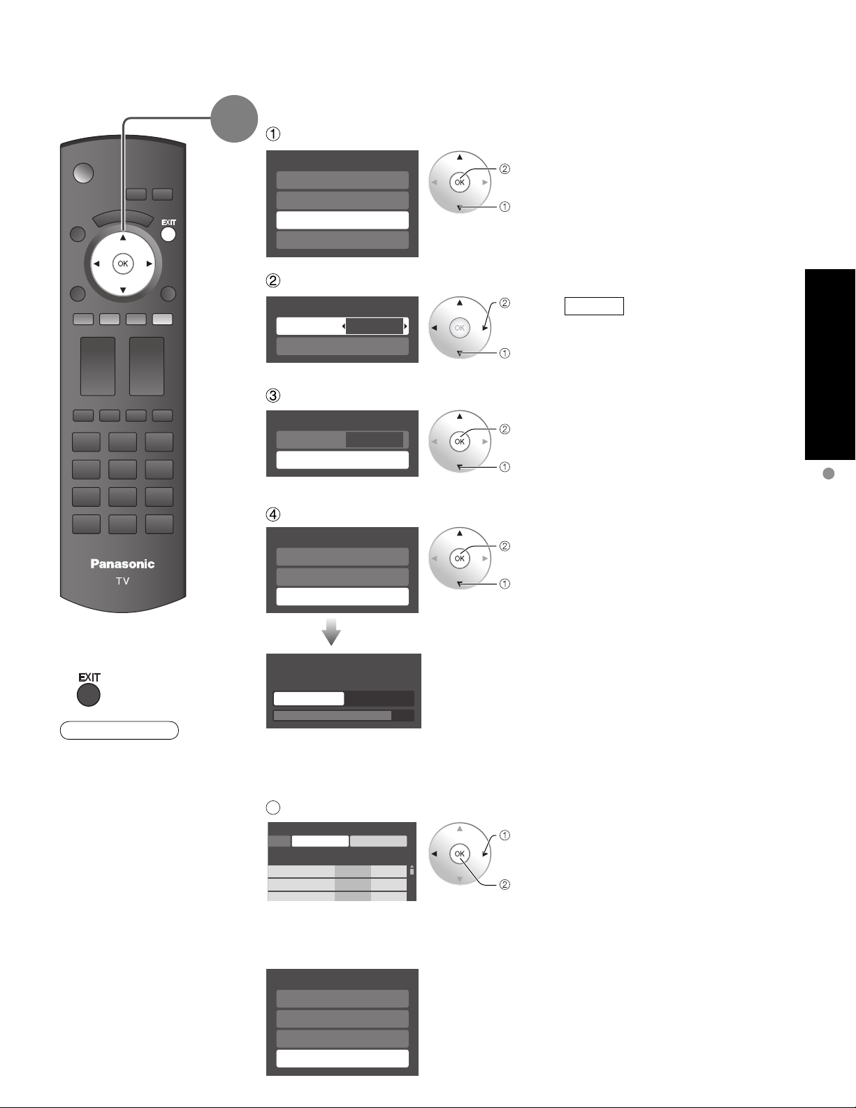
4
Auto channel setup
Select “Auto program”
First time setup
Language
Clock
Auto program
Picture
next
select
Select “ANT in”
Program channel
ANT in
Auto
Cable
set
select
ANT in
Cable: Cable TV
Antenna: Antenna
Select “Auto”
Program channel
ANT in
Auto
Cable
next
select
Select scanning mode (ALL channels/Analog only/Digital only)
Auto program
All channels
Analog only
Digital only
ok
select
Quick Start Guide
First Time Setup
Press to exit from
■
menu screen
Note
About broadcasting
•
systems
Analog (NTSC):
traditional TV
programming
Digital (ATSC):
new programming
that allows you to
view more channels
featuring high-quality
video and sound
Auto program
Scanning digital channel
progress
Quit 40%
Start scanning the channels
Available channels (analog/digital)
•
are automatically set.
All channels: Scans digital and analog channels
Analog only: Scans Analog channels only
Digital only: Scans Digital channels only
5
Confirm registered channels
rogram
Apply Cancel
aption Favorite Add
.
.
.
If OK is not pressed after selecting “Apply”, the channels will not be saved.
•
If you perform scanning more than twice, previously saved channels are erased.
•
...
Yes
...
Yes
...
Yes
select
“Apply”
ok
First time setup
Language
Clock
Auto program
Picture
(Refer to p. 26)
19
Page 20
--
SUB
MENU
SUB
MENU
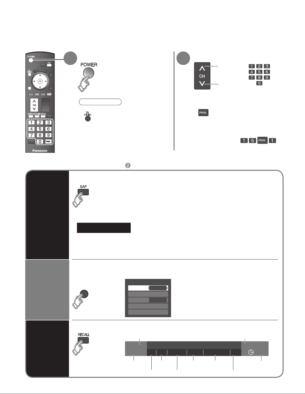
Watching TV
-
Connect the TV to a cable box/cable, set-top-box, satellite box, or antenna cable (p. 10-15)
Turn power on Select a channel number
1 2
SUB
MENU
Note
If the mode is not TV, press
•
and select TV. (p. 24)
Other Useful Functions (Operate after )
■
To directly input the digital channel
■
number
example: CH15-1: -
up
down
When tuning to a digital
channel, press the button to
enter the minor number in a
compound channel number.
or
Listen
with SAP
(Secondary
Audio
Program)
Display the
SUB MENU
Selects Audio Mode for watching TV
■
Digital mode
•
Press SAP to select the next audio track (if available) when receiving a digital channel.
Audio track 1 of 2
Analog mode
•
Press SAP to select the desired audio mode.
• Each press of SAP will change the audio mode. (Stereo/SAP/Mono)
Press SUB MENU to show sub menu screen. (p. 28)
■
This menu consists of shortcuts to convenient functions.
SUB
MENU
(English)
Setup SUB MENU
Surf mode
Set favorite
CC
Caption select
Signal meter
All
Off
20
Information
Recall
Displays or removes the channel banner.
■
Channel
15-2 12:30 pm
ABC-HD
Station
identifier
THE NEWS
CC SAP
SAP
indication
Closed caption
TV-G 1080i Standard 4:3
Signal
resolution
Rating Level
Picture
mode
Aspect ratio
Clock
30
Sleep timer
remaining time
Page 21
Favorite channels
1/3
1
2
3
4
Set favorite 1/3
1
2
3
---
---
---
---
4
Set favorite 1/3
1
2
3
4
SUB
MENU
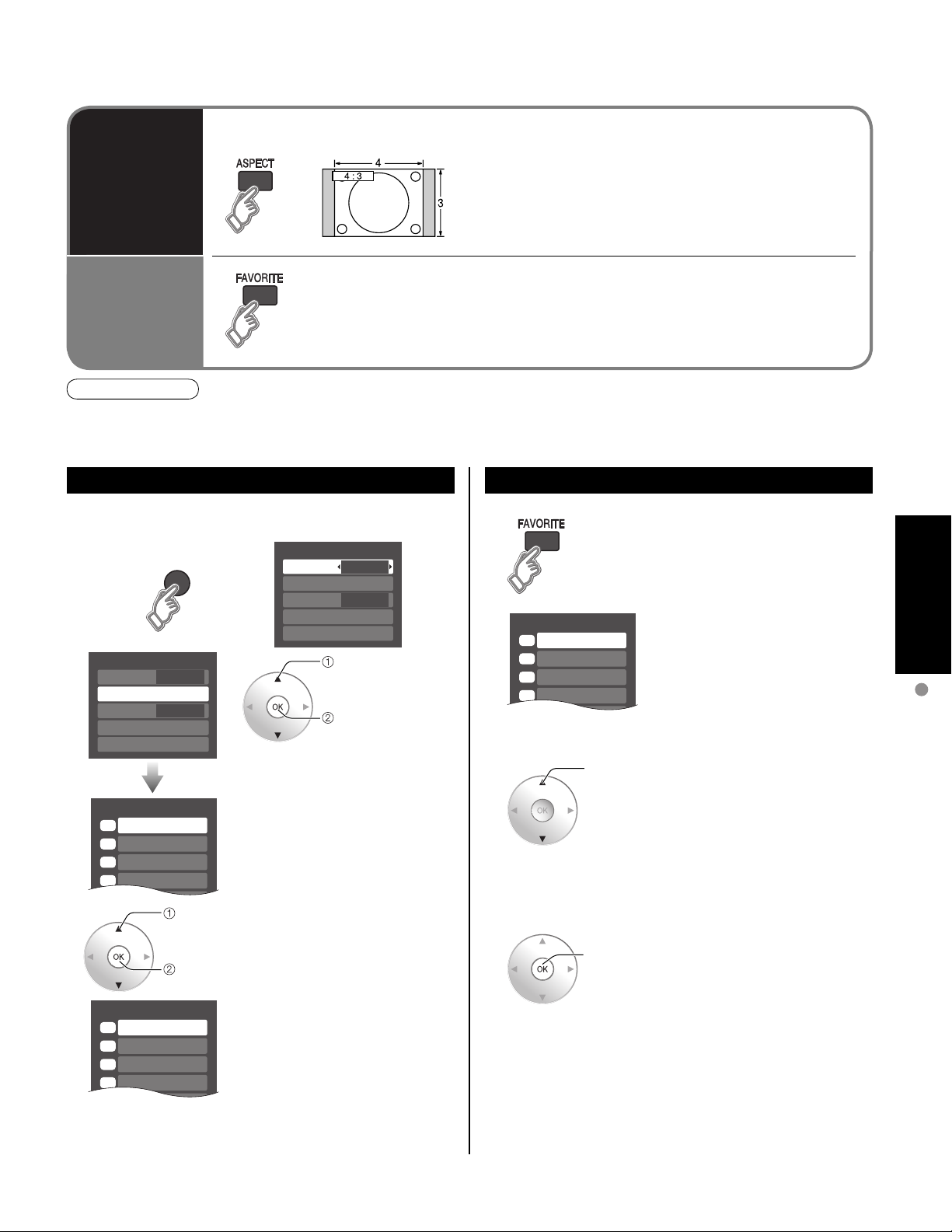
Press ASPECT to cycle through the aspect modes. (p. 43)
■
Change
aspect
ratio
FAVORITE
Call up
a favorite
channel
Note
Reselect “Cable” or “Antenna” in “ANT in” of “Program channel” to switch the signal reception between cable TV
•
and antenna. (p. 19, 35)
The channel number and volume level remain the same even after the TV is turned off.
•
■
Channel numbers registered in Favorite are displayed on the favorite tune
screen. Select the desired broadcast station with the cursor or use number
buttons. (see below)
• 480i, 480p: FULL/JUST/4:3/ZOOM
• 1080p, 1080i, 720p: FULL/H-FILL/JUST/4:3/ZOOM
Set Favorite Feature
1 Display the SUB MENU.
SUB
MENU
Setup SUB MENU
2
Surf mode
Set favorite
CC
Caption select
Signal meter
• Press FAVORITE repeatedly
3 Press ▲▼to highlight a position
• You can also use the NUMBER
26-1 - - -
All
Off
select
ok
Setup SUB MENU
Surf mode
Set favorite
CC
Caption select
Signal meter
to change between pages (1/3,
2/3, 3/3, or exit).
on the list.
Then, press OK to save the
displayed channel in that position.
buttons (1-9 and 0) to select a
list number (1-9 and 0). By doing
so, the displayed channel will
be saved on that list number
without pressing OK.
All
Off
select
“Set favorite”
ok
Use Favorite Feature
1 Press FAVORITE.
• Press FAVORITE repeatedly
to change between pages (1/3,
2/3, 3/3, or exit).
26-1 - - -
2 Press ▲▼ or a Numbered key
select
(1-9 and 0) to highlight a channel
on the list.
• Selecting a channel number
from the list with the number
button will display the channel
directly.
3 Press OK to display the
ok
highlighted channel.
Viewing
Watching TV
•
A saved channel can be removed from the list by holding
•
Pressing ◄ changes the page backward. Pressing ► changes the page forward.
To delete a favorite channel
down OK while its position is highlighted.
To change the page
21
Page 22
Viewing from SD Card
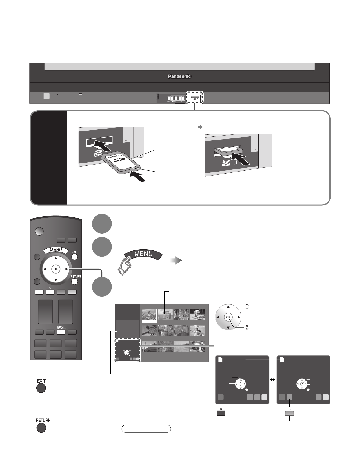
You can view photos taken with a digital camera or digital video camera and saved on an SD card.
(Media other than SD Cards may not be reproduced properly.)
SD
Card
Insert the card
•
Label
surface
Push until a
click is heard
Compliant card type (maximum capacity): SDHC Card (4 GB), SD Card (2 GB), miniSD Card
•
(1 GB) (requiring miniSDCard adapter)
Remove the card
•
Press in lightly on SD Card, then release.
Insert the SD Card
1
For cautions and details on SD Cards (p. 44)
•
Display menu
2
Select “Memory card”
Select the data to be viewed
3
Thumbnail view
22
Press to exit from
■
menu screen
Press to return
■
to the previous
screen
Photo viewer
Total
Information
No.
Date
01/01/2007
Pixel
Select
R YG B
12
101-0365
1600x1200
Accessing
Slide show
Selected picture information is displayed.
No.:Image number or file name is
Date: Date of recording is displayed.
Pixel: Display resolution is displayed.
Total number of images
Depending on the JPEG format, “Information” contents may not be displayed
•
correctly. Refer to p. 44 (Data format for SD card browsing) for details.
101-0365 101-0366 101-0367 101-0368
101-0369 101-0370 101-0371 101-0372
OK
101-0373 101-0374 101-0375 101-0376
RETURN
displayed.
Note
Navigation area
Accessing
Rotate
Prev.
R YG B
Slide show
(to Slide show)
select
view
Next
RETURN
Present status
(While readingthe data)
Accessing
Prev.
R YG B
Single
(to Single photo display)
Pause
Next
RETURN
Page 23
Viewing from a GalleryPlayer SD Card
Picture 1/2
Normal
Picture mode
Picture
Brightness
Set
Vivid
0
0
View
4
Rotate
Prev.
Next
RETURN
R YG B
Slide show
Navigation area
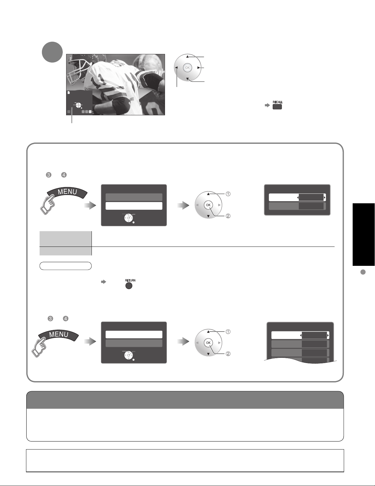
Displays one at a time
To previous photo
To display/hide Navigation area
•
Rotate 90 degrees (counter-clockwise)
To next photo
Rotate 90 degrees (clockwise)
To change the view (Slide show mode, adjusting images, etc.)
To watch photos in Slide show mode
■
In or
JPEG menu
Picture
JPEG setup
Select
Disp. time
Repeat
Note
For large image sizes, the display time will be longer than the number of seconds set.
•
To stop in mid-cycle Press
•
To adjust picture
■
You can set how many seconds each image is displayed in Slide show mode.
(1-10/15/20/30/45/60/120 sec)
Turn the Slide show Repeat function On or Off.
OK
RETURN
select
“JPEG
setup”
ok
When MENU is pressed, the “JPEG menu” is displayed.
or
In
JPEG menu
Picture
JPEG setup
Select
OK
RETURN
select
“Picture”
ok
Picture menu (p. 26)
JPEG setup
Disp. time
Repeat
5
On
Viewing
Viewing from SD Card
You can view high-definition art and photography purchased on or downloaded to an SD card. GalleryPlayer
provides pre-loaded SD cards with copy-protected imagery and images for download to your computer that
can be saved on an SD card for display on your television.
GalleryPlayer images are available for a fee from GalleryPlayer, Inc.
23
Page 24
Watching Videos and DVDs
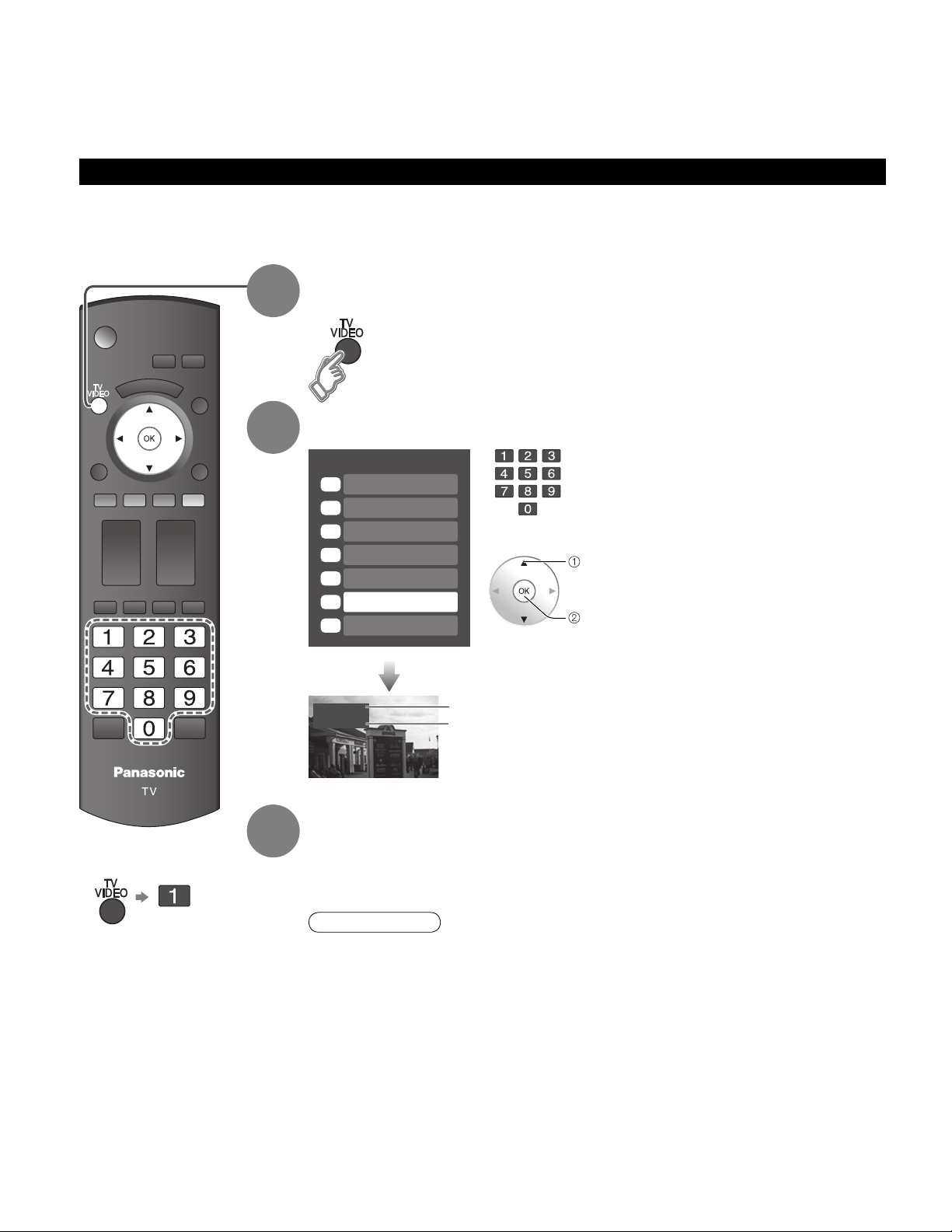
If you have some equipment connected to the TV, you can watch videos and DVDs on the TV’s screen.
Input Select
You can select the external equipment to access.
With the connected equipment turned On
1
Display the Input select menu
To return to TV
■
2
3
Select the input mode
Input select
1
TV
2
Component 1
3
Component 2
HDMI 1
4
HDMI 2
5
Video 1
6
Video 2
7
Video 1
VCR
or
select
enter
(example)
Terminal
Label
(example)
Press corresponding NUMBER
button on the remote control to
select the input of your choice.
Select the input of your choice,
then press OK.
During the selection, if no action
•
is taken for several seconds, the
“Input select” menu disappears.
The terminal and label of
•
the connected equipment is
indicated.
To label each of the inputs please
refer to p. 36-37.
Operate the connected equipment using the remote
control supplied with the equipment.
24
Note
For details, see the manual of the equipment.
•
Page 25
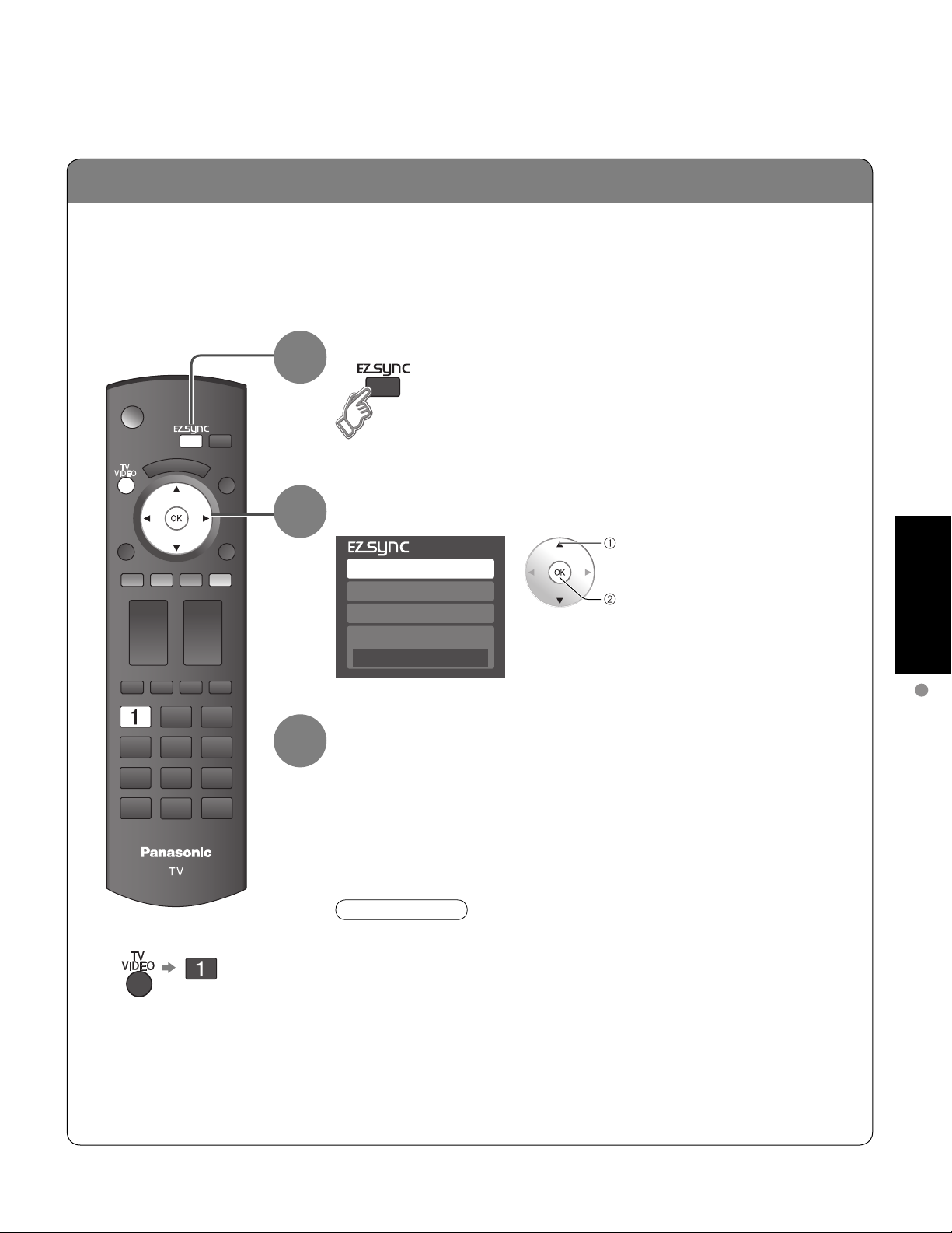
EZ Sync
TM
If you connect equipment that has “HDAVI Control 2” function to a TV with HDMI cable, you can
enjoy using more convenient functions. For details, refer to “EZ Sync Control” on p. 30-31.
Display EZ Sync menu
1
To return to TV
■
2
3
Select the equipment
select
DVD recorder
Home theater
HD camcorder
Speaker output
TV
Operate
You can operate the selected equipment with the TV’s remote
control.
Follow the menu of the equipment and enjoy watching.
For the remote control operations, refer to p. 31.
Note
For details, see the manual for the equipment or ask your local dealer.
•
enter
Viewing
Watching Videos and DVDs
25
Page 26
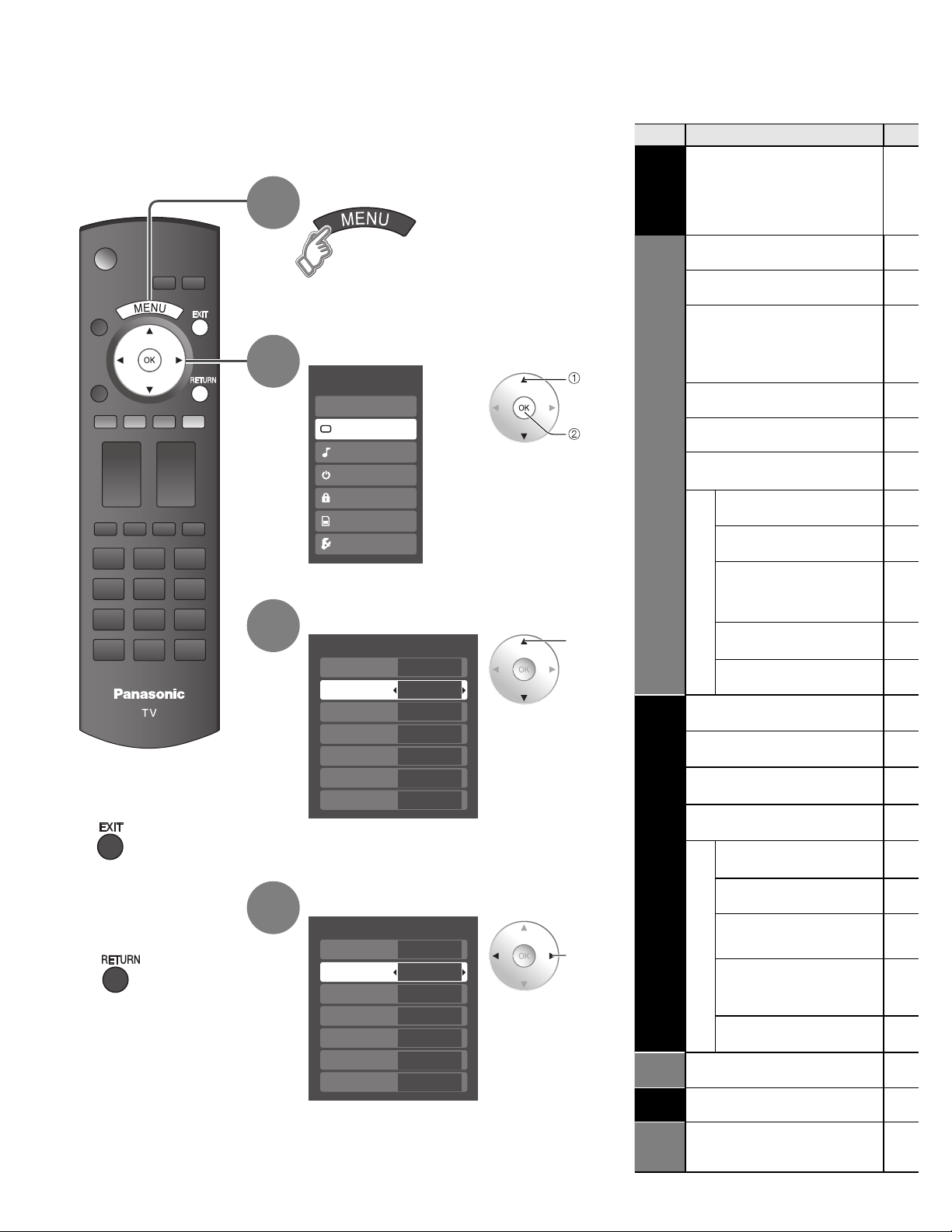
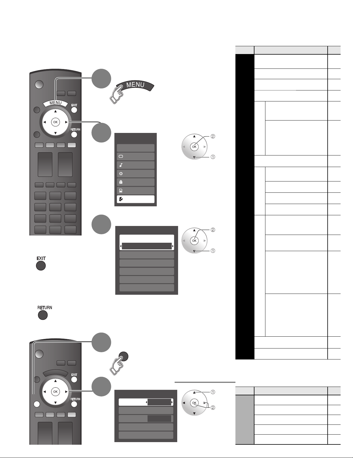
How to Use Menu Functions
Various menus allow you to make settings for the picture, sound, and
other functions so that you can enjoy watching TV in the way best
suited for you.
Display menu
1
Displays the functions that can be set
•
(varies according to the input signal)
Select the menu
2
Menu
EZ Sync
Picture
Audio
Timer
Lock
Memory card
Setup
select
next
Menu list
■
Menu Item
EZ Sync
DVD recorder,
Home theater,
HD camcorder,
Speaker output
Normal
Picture mode
Picture, Brightness,
Color, Tint, Sharpness
Color temp.
Picture
Color mgmt.
Zoom adjust
Video NR
Other adjust
3D Y/C filter
Press to exit from
■
menu screen
Press to return
■
to the previous
screen
3
4
Select the item
Picture 1/2
Normal
Picture mode
Picture
Brightness
Color
Tint
Sharpness
(example: Picture menu)
Set
Vivid
0
0
0
0
0
Adjust or select
Picture 1/2
Normal
Picture mode
Picture
Brightness
Color
Tint
Sharpness
(example: Picture menu)
Set
Vivid
0
0
0
0
0
select
adjust
or
select
Audio
Timer
Lock
Color matrix
MPEG NR
Black level
Normal
Bass
Treble
Balance
AI sound
Other adjust
Surround
Speaker output
HDMI 1 in
HDMI 2 in
Audio leveler
Sleep, Timer 1-5
26
Memory
Card
Memory card
Page 27
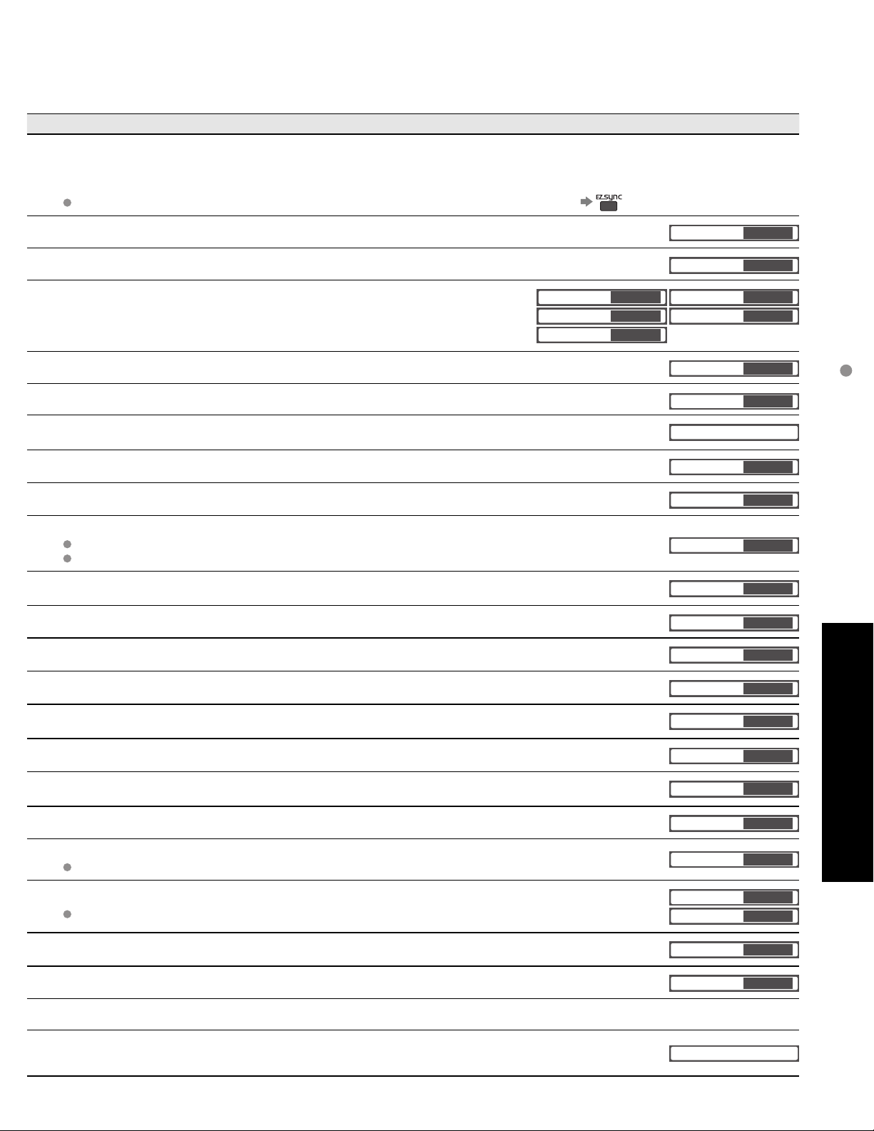
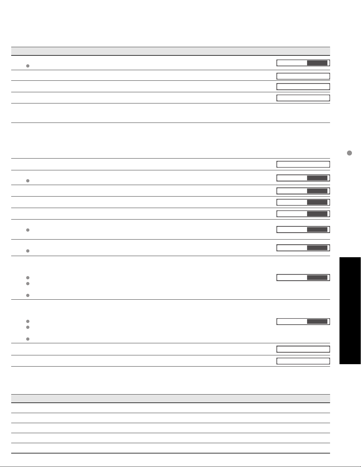
Adjustments/Configurations (alternatives)
[DVD recorder/Home theater/HD camcorder]
Select equipment to access and operate. (p.30)
[Speaker output]
Select audio output. (Home theater/TV) (p. 30)
EZ Sync menu is accessible directly by pressing the EZ Sync button on the remote control. (p. 25)
Resets all picture adjustments to factory default settings except for “Other adjust” (Set/No)
Basic picture mode (Vivid/Standard/Cinema/Custom) (p. 45)
Adjusts color, brightness, etc. for each picture mode to suit your taste
Picture
Brightness
Color
Selects level of warm colors (red) and cool colors (blue) (Cool/Normal/Warm)
On: Enhances green and blue color reproduction, especially outdoor scenes. (On/Off)
Adjusts vertical alignment and size when aspect setting is “ZOOM” (p. 43)
Reduces noise, commonly called snow. Leave it off when receiving a strong signal. (Off/On)
Minimizes noise and cross-color in the picture. (On/Off)
Selects image resolution of component-connected devices (HD/SD)
SD: Standard Definition HD: High Definition
Only 480p signal accepted; regular TV (NTSC) is not available.
Reduces noise of specific digital signals of DVD, STB, etc. (On/Off)
Selects Dark or Light. Valid only for external input signals. (Dark/Light)
+20
0
0
Normal
Picture mode
Tint
Sharpness
Color temp.
Color mgmt.
Zoom adjust
Video NR
3D Y/C filter
Color matrix
MPEG NR
Black level
0
0
Set
Vivid
Cool
On
Off
Off
SD
Off
Light
How to Use Menu Functions
(picture, sound quality, etc.)
Resets Bass, Treble and Balance adjustments to factory default settings. (Set/No)
Increases or decreases the bass response.
Increases or decreases the treble response.
Emphasizes the left / right speaker volume.
Equalizes overall volume levels across all channels and external inputs. (On/Off)
Enhances audio response when listening to stereo. (On/Off)
Switches to “Off” when using external speakers (On/Off)
“AI sound”, “Surround”, and “Audio leveler” do not work if “Off” is selected
Selects according to the signal when HDMI is connected (Auto/Digital/Analog)
Auto: Automatically selects Analog / Digital signal
Minimizes volume disparity after switching to external inputs
The TV can automatically turn On/Off at the designated date and time (p. 38)
Locks the channels and programs (p. 32)
Displays SD card data (p. 22)
Normal
Bass
Treble
Balance
AI sound
Surround
Speaker output
HDMI1 in
HDMI2 in
Audio leveler
Sleep
Memory card
+ 4
0
0
0
Set
Advanced
On
Off
On
Auto
Auto
60
In AV mode, the Audio menu and Setup menu give fewer options.
•
27
Page 28
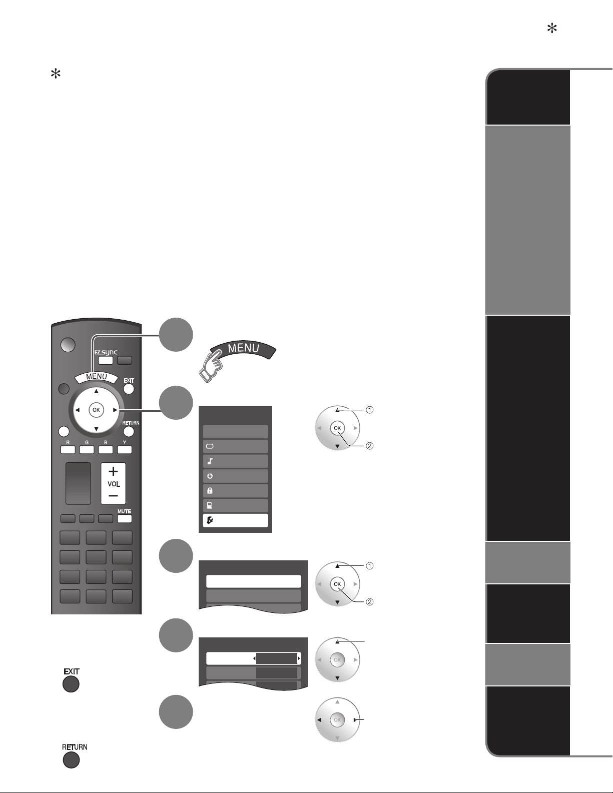
SUB
MENU
SUB
MENU
How to Use Menu Functions
Various menus allow you to make settings for the picture, sound, and
other functions so that you can enjoy watching TV in the way best
suited for you.
Display menu
1
Displays the functions that can be set
•
(varies according to the input signal)
Select “Setup”
2
2
Menu
EZ Sync
Picture
Audio
Timer
Lock
Memory card
Setup
next
select
Menu list
■
Menu Item
Surf mode
Language
Clock
Program channel
External devices
Input labels
Monitor out
CC
EZ Sync setting
EZ Sync
Power off link
Setup
Power on link
Press to exit from
■
menu screen
Press to return
■
to the previous
screen
3
1
Select the item
Setup 1/2
Surf mode
All
Language
Clock
Program channel
External devices
CC
Display SubMenu
SUB
MENU
next
select
Default speakers
Auto power on
Side bar
Other adjust
No signal shut-off
No action shut-off
About
Reset
28
SUB
MENU
2
Select the item
Setup SUB MENU
Surf mode
Set favorite
CC
Caption select
Signal meter
All
Off
select
set
or
next
Sub menu list
■
Menu Item
SUB MENU
Surf mode
Setup
Set favorite
CC
Caption select
Signal meter
Page 29
(Continued)
Adjustments/Configurations (alternatives)
Sets the mode to select the channel with Channel up/down button (Favorite/All)
Favorite: Only channels registered as FAVORITE (p. 35)
Selects the screen menu language (p. 18)
Surf mode
Language
All
Adjusts the clock (p. 18)
Sets channels (p. 34)
Selects the terminal and label of the external equipment (p. 36)
[Comp. 1/Comp. 2/HDMI 1/HDMI 2/Video 1/Video 2]
To prevent howling and image oscillation, stops output of the pictures and audio specified in this menu.
(p. 36) (On/Off)
Displays subtitles (Closed Caption) (p. 36)
Controls equipment connected to HDMI terminals (p. 30) (On/Off)
“Power off link”, “Power on link”, and “Default speakers” cannot be selected if “Off” is set.
Sets “Power off link” of HDMI connection equipment (p. 30) (Set/No)
Sets “Power on link” of HDMI connection equipment (p. 30) (Set/No)
Selects the default speakers (p. 30) (TV/Theater)
Turns TV On automatically when the cable box or a connected device is turned On (No/Set)
The “Sleep” timer, “On / Off timer”, and “First time setup” will not function if “Auto power on” is set.
(p. 38)
Change the brightness of the side bar (Bright/Off/Dark/Mid) (4:3 mode only)
The recommended setting is “Bright” to prevent panel “Image retention”. (p. 45)
To conserve energy, the TV automatically turns off when NO SIGNAL continues more than 10 minutes.
(Set/No)
Note
Not in use when setting “Auto power on”, “On/Off Timer”, “Lock”, “SD Mode”, or Digital channel.
“No signal shut-off was activated” will be displayed for about 10 seconds when the TV is turned on for
the first time after turning the power off by “No signal shut-off”.
The on-screen display will flash 3, 2 and 1 to indicate the last three (3) remaining minutes prior to the shut-off.
To conserve energy, the TV automatically turns off when no operation of remote or front panel key
continues for more than 3 hours. (No/Set)
Note
Not in use when setting “Auto power on” or “On/Off Timer”.
“No action shut-off was activated” will be displayed for about 10 seconds when the TV is turned on for
the first time after turning the power off by “No action shut off”.
The on-screen display will flash 3, 2 and 1 to indicate the last three (3) remaining minutes prior to the shut-off.
Clock
Program channel
CC
EZ Sync
Power off link
Power on link
Default speakers
Auto power on
Side bar
No signal shut-off
No action shut-off
How to Use Menu Functions
(picture, sound quality, etc.)
On
Set
Set
TV
No
Bright
Set
Advanced
No
Displays TV version and software license.
Performing Reset will clear all items set with Setup, such as channel settings. (p. 34)
Adjustments/Configurations (alternatives)
Sets the mode to select the channel with Channel up/down button (Favorite/All)
Sets favorite channels. (p. 21)
Displays Closed Caption. (p. 36) (Off/On)
Changes the station identifier. (p. 35)
Checks the signal strength if interference or freezing occurs on a digital image. (p. 34)
About
Reset
29
Page 30
SUB
MENU
Setup 2/2
EZ Sync setting
Other adjust
About
EZ Sync setting
EZ Sync
Power off link
Power on link
On
Set
Set
TM
EZ Sync
Simultaneously control all Panasonic “HDAVI Control” equipped components using one button
on one remote.
Enjoy additional HDMI Inter-Operability with Panasonic products which have “HDAVI Control” function.
This TV supports “HDAVI Control 2” function.
Connections to some Panasonic equipment (DVD Recorder DIGA, HD Camcorder, RAM theater,
Player theater, Amplifier, etc.) with HDMI cables allow you to interface automatically.
The equipment with “HDAVI Control” function enables the following operations:
Automatic Input Switching, Power on link, Power off link and Speaker control (p. 31).
In addition, the equipment with “HDAVI Control 2” function enables the following operation:
EZ Sync Control only with TV’s remote control (for “HDAVI Control 2”) (p. 31).
EZ Sync “HDAVI Control”, based on the control functions provided by HDMI which is an industry standard
known as HDMI CEC (Consumer Electronics Control), is a unique function that we have developed and added.
As such, its operation with other manufacturers’ equipment that supports HDMI CEC cannot be guaranteed.
For the first time / When adding new equipment, reconnecting the equipment or changing the setup.
■
After the connection turn the equipment on and then switch the TV on.
Select the input mode to HDMI 1 or HDMI 2 (p. 24), and make sure that an image is
displayed correctly.
This function needs an HDMI compliant (fully wired) cable. Non-HDMI-compliant cables cannot
•
be utilized.
It is recommended that you use Panasonic’s HDMI cable.
Recommended part number:
RP-CDHG15 (4.9 ft/1.5 m), RP-CDHG30 (9.8 ft/3.0 m), RP-CDHG50 (16.4 ft/5.0 m)
“HDAVI Control
TM
Automatic
Input
Switching
Speaker
control
”
SUB
MENU
Press to exit from
■
menu screen
1
2
3
4
Display menu
Select “Setup”
Menu
EZ Sync
Picture
Audio
Timer
Lock
Memory card
Setup
Select “EZ Sync setting”
Select “EZ Sync”
select
next
select
next
select
EZ Sync
Control
only with
TV’s remote
control
(for “HDAVI
Control 2”)
Power on
link
Power off
link
Default
speakers
Press to return
■
to the previous
screen
30
5
Select “On”
(default is On)
If no HDMI equipment is connected or standard HDMI
•
equipment (non- “EZ Sync”) is used, set to “Off”.
change
One-touch
theater
playback
Page 31
At the start of the DIGA, Player theater, or RAM theater playback, the TV’s input automatically switches to the input
SUB
MENU
based on the playback equipment.
For the RAM theater, the speakers automatically switch to the theater system.
•
If using the DIGA operation, the TV’s input automatically switches to the DIGA and DIGA menu is displayed.
You can select Home theater, or TV speakers for audio output.
Control theater speakers with the TV’s remote control.
This function is available only when Panasonic Amplifier or Player theater is connected.
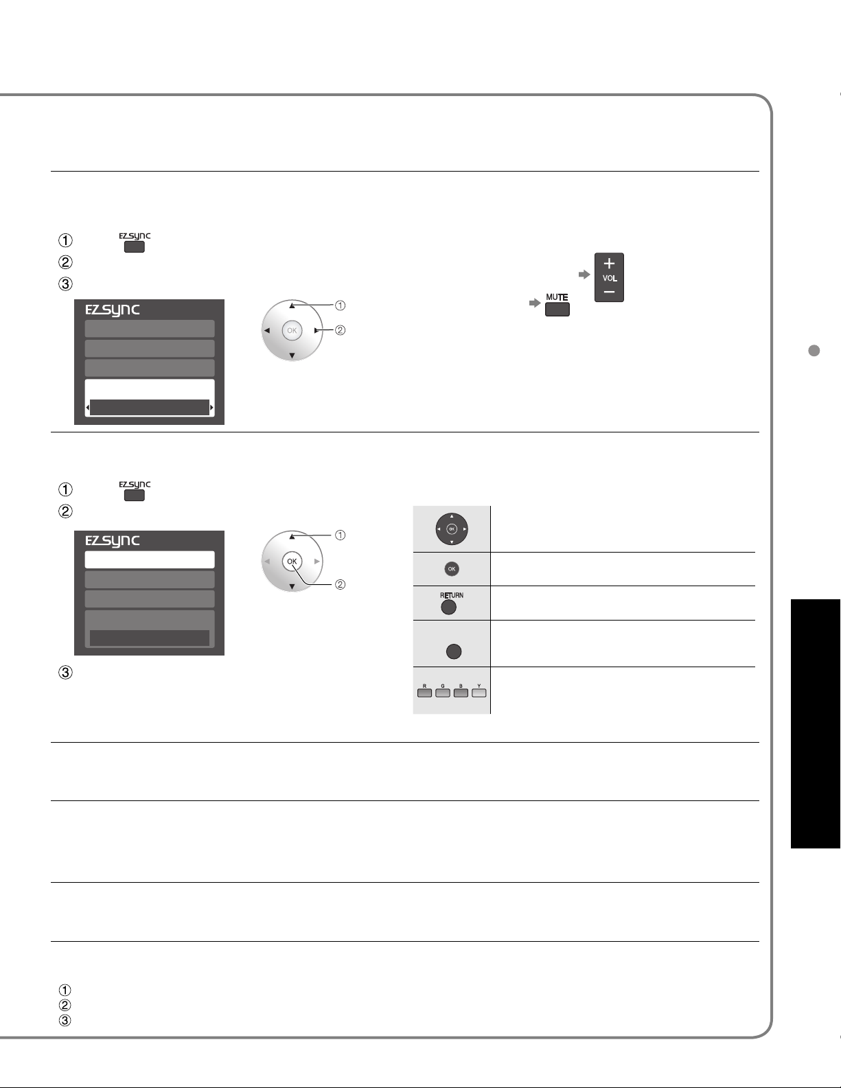
Home theater: Adjustment for equipment
Press
Select “Speaker output”
Select “Home theater” or “TV”
select
■
Volume up / down
Mute
DVD recorder
Home theater
HD camcorder
Speaker output
TV
In the EZ Sync menu, you can select HDMI connected Panasonic equipment and access it quickly. Continue using
your TV’s remote control to operate the equipment, pointing it at the TV.
Press
Select the equipment you want to access.
DVD recorder
Home theater
HD camcorder
Speaker output
TV
Operate the equipment with the TV’s remote
control, pointing it at the TV.
To operate the equipment, read the manual of the
•
equipment.
You can select available
items only.
change
select
access
The sound of the TV is muted.
•
When the equipment is turned off, TV speakers
•
become active.
Selecting “Home theater” turns the equipment on
•
automatically if it is in standby mode.
TV: The TV speakers are active.
■
Available TV’s remote control buttons
■
Move the cursor/Select
Set/Access
Return to the previous menu
SUB
MENU
Display the Functions menu on the
equipment
Available when the purpose of the keys is
displayed on screen
EZ Sync
TM
“HDAVI Control
TM
”
Advanced
When “Set” is selected (p. 29), TV is turned on automatically and switches to the appropriate HDMI input whenever
EZ Sync compatible equipment is initially turned on and Play mode is selected.
When “Set” is selected (p. 29) and the TV is turned off, all connected EZ Sync compatible equipment is also
automatically turned off.
DIGA (Panasonic DVD Recorder) will not turn off if it is still in rec mode.
•
Caution: The TV remains on even if the EZ Sync compatible equipment is turned off.
“TV” is the default setting. To set the Home Theater system as default speakers, change the default speakers
setting from “TV” to “Theater”. Sound will be output from the Home Theater whenever the TV is powered on.
If the “ONE TOUCH PLAY” key is pressed on the remote control for Panasonic Home Theater system, the following
sequence of operations is performed automatically.
Home Theater power switches On, and playback begins.
TV power switches On, and the playback screen is displayed.
Audio is muted on the TV and switches to the theater system.
31
Page 32
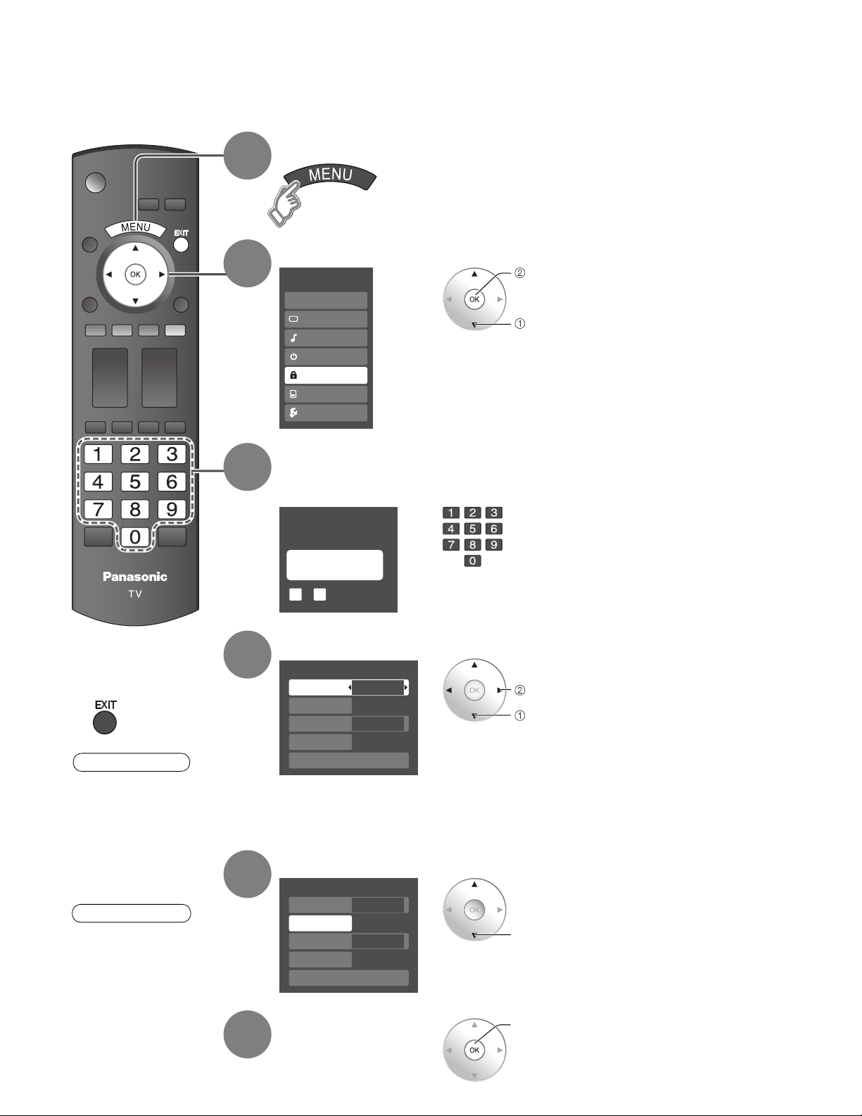
Lock
You can lock specified channels or shows to prevent children from watching objectionable content.
Display menu
1
Select “Lock”
2
3
Menu
EZ Sync
Picture
Audio
Timer
Lock
Memory card
Setup
Input your 4-digit password
A 4-digit code must be entered to view a blocked program or change rating settings.
next
You will be asked to enter your
password each time you display the
Lock menu.
select
Press to exit from
■
menu screen
Caution
Make a note of your
•
password in case
you forget it. (If you
have forgotten your
password, consult your
local dealer.)
Note
When you select a
•
locked channel,
a message will be
displayed that allows
you to view the
channel if you input
your password.
4
5
6
Create password
Enter password.
----
9
0
-
Select the Lock mode
Lock
Mode
Channel
Game
Program
Change password
Off
Off
Off
Off
Select the item
Lock
Mode
Channel
Game
Program
Change password
Custom
Off
Off
Off
Set
set
select
select
set
If it is your first time entering the
•
password, enter the password
twice in order to register it.
Off: Unlocks all the lock settings
•
•
•
•
of “Channel”, “Game” and
“Program”.
All: Locks all the inputs
regardless of the lock settings
of “Channel”, “Game” and
“Program”.
Custom: Locks specified inputs of
“Channel”, ”Game” and
“Program”.
“Channel”, ”Game” and “Program”
will grey out unless “Custom” is
selected in “Mode”.
32
Page 33
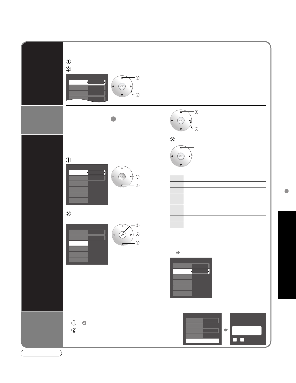
Channel lock
Mode
Channel 1
Channel 2
Channel 3
Custom
3
4
-
To select the channel or the rating of the program to be locked
■
Select up to 7 (1-7) channels to be blocked. These channels will be blocked regardless of the
program rating.
Select “Mode” and set to “Custom”
Channel
lock
Select channel to lock.
select
set
To lock/unlock all channels:
•
Select “Mode” and set to “All” or “Off”.
All: Locks all channels
Off: Unlocks all channels
Game lock
Program
lock
Locks Channel 3, Channel 4 and external inputs.
Select “Game” in 5 and set to “On”.
To set a rating level
■
“V-chip” technology enables restricted shows
to be locked according to TV ratings.
Select “Mode” and set to “On”.
Program lock
Mode
Monitor out
MPAA
U.S.TV
C.E.L.R.
C.F.L.R.
On
On
Off
Off
Off
Off
set
select
Select the rating category you wish
to follow
Program lock
Mode
Monitor out
MPAA
U.S.TV
C.E.L.R.
C.F.L.R.
MPAA: U.S movie ratings
•
U.S.TV: U.S TV program ratings
•
C.E.L.R.: Canadian English ratings
•
C.F.L.R.: Canadian French ratings
•
On
On
Off
Off
Off
Off
next
set
select
select
On: Locks
set
Off: Unlocks
Select the rating to be locked
select
Example of “MPAA” (U.S movie ratings)
NR No rating
G General Audience: All ages admitted
PG Parental Guidance Suggested
PG-13
NC-17 No one 17 and under admitted
•
■
Parents Strongly Cautioned: Inappropriate for
children under 13
Restricted: Under 17 requires accompanying
R
parent or adult guardian
X Adults only
To get more information (p. 42)
To disable recording of the locked
program
Select “Monitor out” and set to “On”.
Program lock
Mode
Monitor out
MPAA
U.S.TV
C.E.L.R.
C.F.L.R.
On
Off
Off
Off
Off
Off
On: Turns on the monitor
terminal output
for programs that
have been set to
“Blocked.”
Off: Turns off the monitor
terminal output
for programs that
have been set to
“Blocked.”
Lock
Advanced
•
•
•
Lock
Mode
Channel
Game
Program
Change password
Off
Off
Off
Off
Change password
Enter new password.
----
9
0
-
Change
password
To change the password
■
In , select “Change password” and press OK
Input the new 4-digit password twice
Note
This television is designed to support the “Downloadable U.S. Region Rating System” when available. (Available only in U.S.A.)
The Off rating is independent of other ratings.
When placing a block on a specific-age-based-rating level, the Off rating and any other more restrictive ratings will also be blocked.
33
Page 34
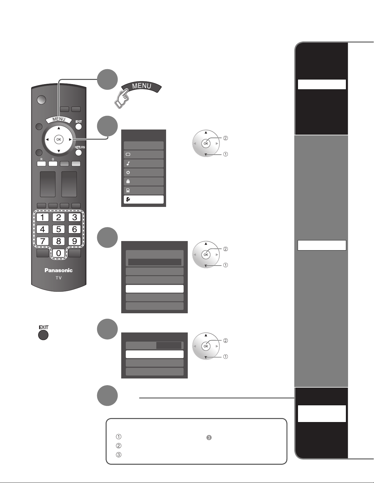
Editing and Setting Channels
The current channel settings can be changed according to your needs and reception
conditions.
Display menu
1
2
Select “Setup”
Menu
EZ Sync
Picture
Audio
Timer
Lock
Memory card
Setup
next
select
Auto
Set
automatically
Press to exit from
■
menu screen
3
4
5
Select “Program channel”
Setup 1/2
Surf mode
All
Language
Clock
Program channel
External devices
CC
Select the function
Program channel
ANT in
Auto
Manual
Signal meter
Cable
Set
next
select
next
select
Manual
Set
manually
34
To reset the settings of setup menu
■
Select “Reset” in Setup menu ( ) and press OK
Input your 4-digit password with number buttons
Select “YES” on the confirmation screen and press OK
Signal
meter
Check
signal
strength
Page 35
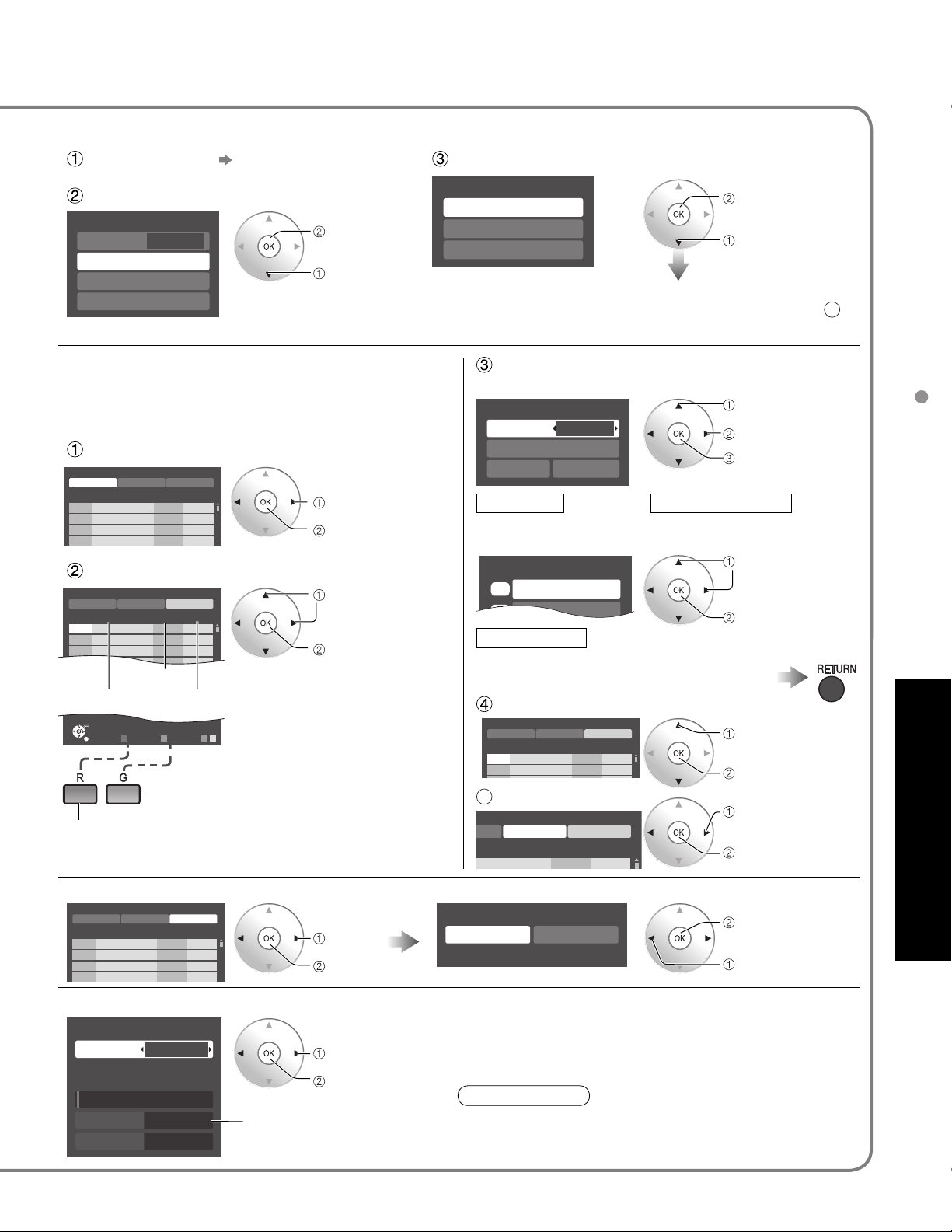
Set favorite 1/3
1
2
Automatically searches and adds active channels to memory.
Select “ANT in”
Select Cable or Antenna
(p. 19)
Select “Auto”
Program channel
ANT in
Auto
Manual
Signal meter
Cable
next
select
•
•
Use this procedure when changing setting of receiving
channels or changing the channel display.
Also, use to add or skip channels from channel list
manually.
Select “Edit”
Manual program
Edit
Cannnel
2...
3...
4...
5...
Manual program
Edit
Cannnel
2...
3...
4...
5...
6...
7...
8...
9...
Select
Go back to previous page
Apply Cancel
Caption Favorite Add
...
...
...
...
Yes
Yes
Yes
Yes
Select the item to be edited
Apply Cancel
Caption Favorite Add
...
...
...
...
...
...
...
Caption
...
OK
R
RETURN Prev. page
Favorite
G B Y
Next page
Proceed to
next page
Yes
Yes
Yes
Yes
Yes
Yes
Yes
Add
Yes
Caption:
•
Changes the station identifier
Favorite:
•
Registers channel to Favorite
List
Add:
•
Adds or skips channels
select
next
select item to edit
(Caption/Favorite/Add)
next
Select scanning mode (p. 19)
Auto program
All channels
Analog only
Digital only
Settings are made automatically
After completing the setting, select “Apply”. (see below 5).
All previously saved channels are erased.
ok
select
Edit
Caption
•
Caption select
Caption
Caption detail
Apply Cancel
---
select
change
set/next
Caption detailCaption
Select the station identifier
Favorite
•
26-1 - - -
Set favorite
Add
•
Press OK to select “Yes (add)” or “No (skip)”
Rename (maximum 7 characters available)
select
next
Select the number
Move cursor to channel number
Manual program
Edit
Cannnel
2...
3...
5
rogram
aption Favorite Add
.
Apply Cancel
Caption Favorite Add
...
...
Select “Apply”
Apply Cancel
...
Yes
select
Yes
Yes
Press OK to tune
to the channel.
select “Apply”
ok
Editing and Setting Channels
Advanced
To cancel the Edit
Manual program
Edit
Cannnel
2...
3...
4...
5...
Check the signal strength if interference is found or freezing occurs on a digital image.
Signal meter
Signal strength
•
Apply Cancel
Caption Favorite Add
...
...
...
...
Channel
Current
Peak level
If “Lock” (p. 32) is activated and “Program channel” is selected, “Enter password.” will be displayed.
1-1
30%
45%
Changes will be lost. Continue?
Yes
Yes
Yes
Yes
select
next
change channel
Yes No
If the signal is weak, check the antenna.
•
If no problem is found, consult your
ok
(returns to “Program
channel”)
select “Y es”
local dealer.
ok
Note
Signal intensity
Not available if “Cable” is selected in “ANT in”
•
(see above).
Effective only for digital antenna channels.
•
35
Page 36
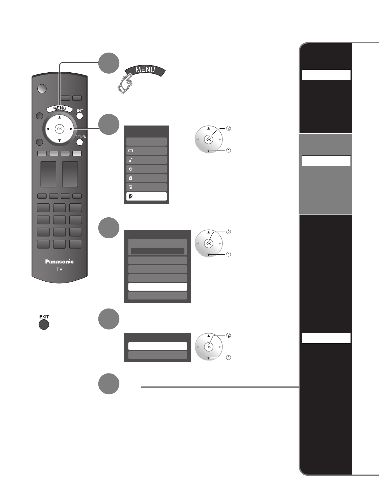
Input Labels/Monitor Out/
Display menu
1
Display
labels of
external
devices
Select “Setup”
2
Menu
EZ Sync
Picture
Audio
Timer
Lock
Memory card
Setup
next
select
Stop output
of the
picture and
audio
Input labels
Monitor out
Press to exit from
■
menu screen
3
4
5
Select “External devices” or “CC”
Setup 1/2
Surf mode
All
Language
Clock
Program channel
External devices
CC
next
select
(External devices)
Select “Input labels” or “Monitor out”
External devices
Input labels
Monitor out
next
select
Set
CC
Display
Closed
Caption
36
Page 37
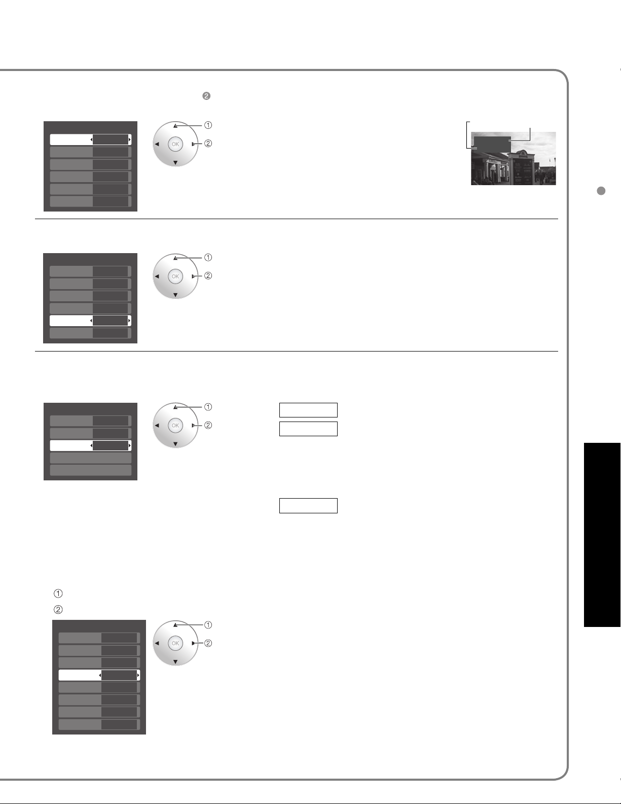
Closed Caption
Devices connected to external input terminals can be labeled for easier identification during input selection.
(In selecting input mode from p. 24 )
Select the terminal and label of the external equipment
■
Input labels
Comp. 1
Comp. 2
HDMI 1
HDMI 2
Video 1
Video 2
To prevent howling and image oscillation, stops output of the pictures and audio specified in this menu. (p. 28)
Select the terminal and set “Off”
■
Monitor out
Comp. 1
Comp. 2
HDMI 1
HDMI 2
Video 1
Video 2
Custom
Custom
3
4
-
-
On
On
On
On
Off
On
select
set
select
set
T erminals: Comp. 1-2/HDMI 1-2/
•
Label: SKIP*/VCR/DVD/CABLE/
•
*
If “SKIP” is selected, the TV/VIDEO
button press will skip its input.
Select “Off” to stop output of picture and audio.
•
(Video 1/Video 2)
Comp. 1/Comp. 2/HDMI 1/HDMI 2 cannot output video
•
signals regardless of “Monitor out” setting.
When equipment (STB, DVD, etc.) is connected to HDMI
or COMPONENT terminals, only audio signals can be
obtained. From the output terminals, no video signals can be
passed.
Video 1-2
DBS/PVR/GAME/AUX/[BLANK]
Label Terminal
Video 1
VCR
[example]
Input Labels/Monitor Out/Closed Caption
The television includes a built-in decoder that is capable of providing a text display of the audio. The program being
viewed must be transmitting Closed Caption (CC) information. (p. 43)
Select the item and set
■
CC
Mode
Analog
Digital
Digital setting
CC reset
The settings in “Analog” or “Digital”
•
depend on the broadcaster.
To make more in-depth display settings in digital programs
■
Select “Digital setting” and press OK
Select the item and set
Digital setting
Size
Font
Style
Foreground
Fore opacity
Background
Back opacity
Outline
On
CC1
Primary
Automatic
Automatic
Automatic
Automatic
Automatic
Automatic
Automatic
Automatic
select
set
select
set
Mode
Analog
CC1-4: Information related to pictures
T1-4: Textual information
Digital
Select the setting.
“Primary”, “Second.”, “Service 3”, “Service 4”, “Service 5”,
•
“Service 6”
Size: Text size
•
Font: Text font
•
Style: Text style (Raised, Depressed, etc.)
•
Foreground: Color of text
•
Fore opacity: Opacity of text
•
Background: Color of text box
•
Back opacity: Opacity of text box
•
Outline: Outline color of text
•
(Identify the setting options on the screen.)
Select “On” (when not using, select “Off”).
(Choose the Closed Caption service of Analog
broadcasting.)
(Appears at bottom of screen)
(Appears over entire screen)
(The Digital Closed Caption menu lets you
configure the way you choose to view the digital
captioning.)
Advanced
To reset the settings
■
Select “CC reset” and press OK
37
Page 38
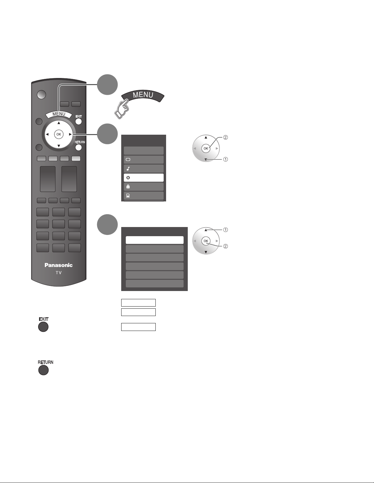
Using Timer
The TV can automatically turn On/Off at the designated date and time.
The Clock must be set before On time/Off time settings. (p. 18)
•
The “Sleep” timer and “On / Off timer” will not function if “Auto power on” (p. 28) is set.
•
Display menu
1
Select “Timer”
2
Menu
EZ Sync
Picture
Audio
Timer
Lock
Memory card
next
select
Press to exit from
■
menu screen
Press to return
■
to the previous
screen
3
Select the timer to set
Timer
Sleep
Timer 1
Timer 2
Timer 3
Timer 4
Timer 5
Sleep
Timer 1
~
Timer 5
Turns Off automatically
Turns On/Off automatically
(5 timers can be set.)
select
next
38
Page 39
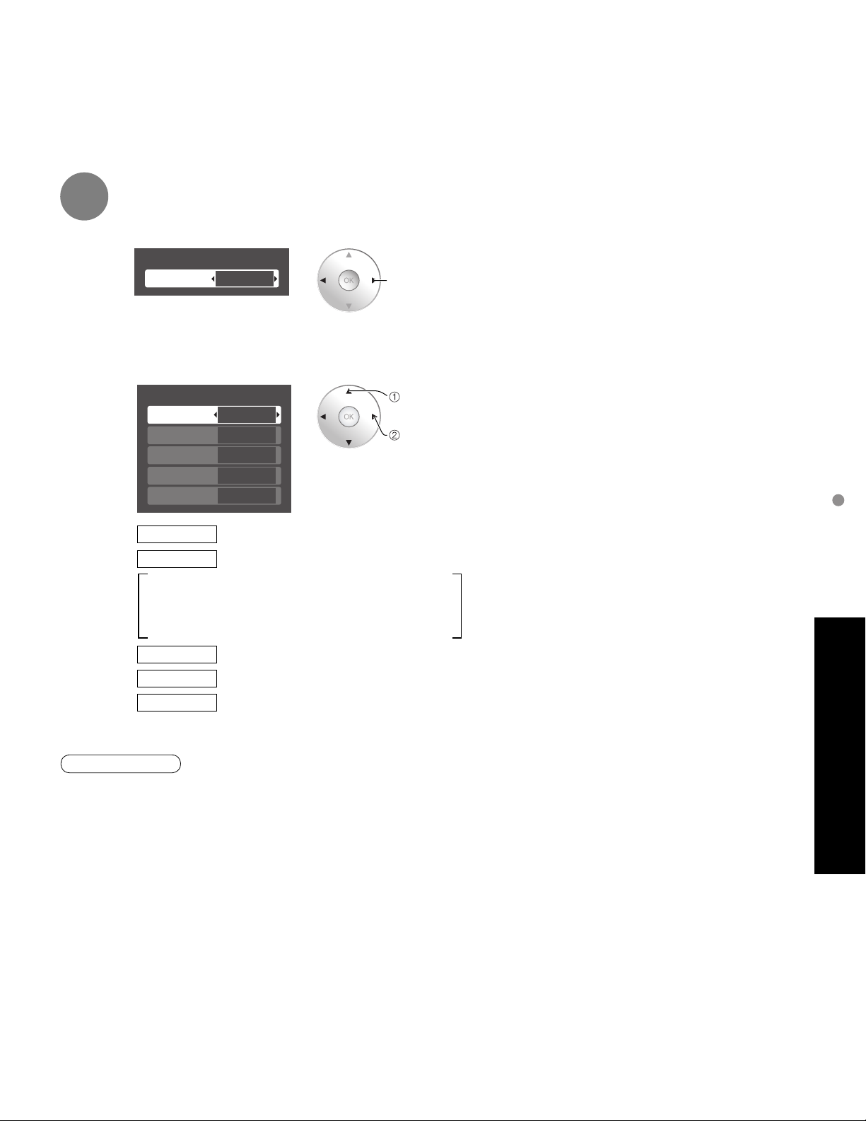
4
Set the timer
To set “Sleep” (Off Timer)
■
Set to shut the unit off after a pre-selected amount of time.
Sleep
Sleep
To set “Timer 1-5” (On/Off Timer)
■
Select the item and set
60
set
0/30/60/90 (minutes)
•
Timer 1
Channel
Day
On time
Off time
Set
Channel
Day
SUN/MON/TUE/WED/THU/FRI/SAT
(displays the nearest future date)
MON-FRI/SAT-SUN/DAILY/EVR SUN/EVR MON/
EVR TUE/EVR WED/EVR THU/EVR FRI/ EVR SAT
On time
Off time
Set
Note
The TV automatically turns Off after 90 minutes when turned On by the Timer. This operation will be
•
cancelled if the Off time is selected or if a key is pressed.
310 - 1
EVR FRI
10:00 AM
11:00 AM
On
Select the channel
Select the day
The time to turn On
The time to turn Off
Timer setting (On/Off)
select
set
Using Timer
Advanced
39
Page 40
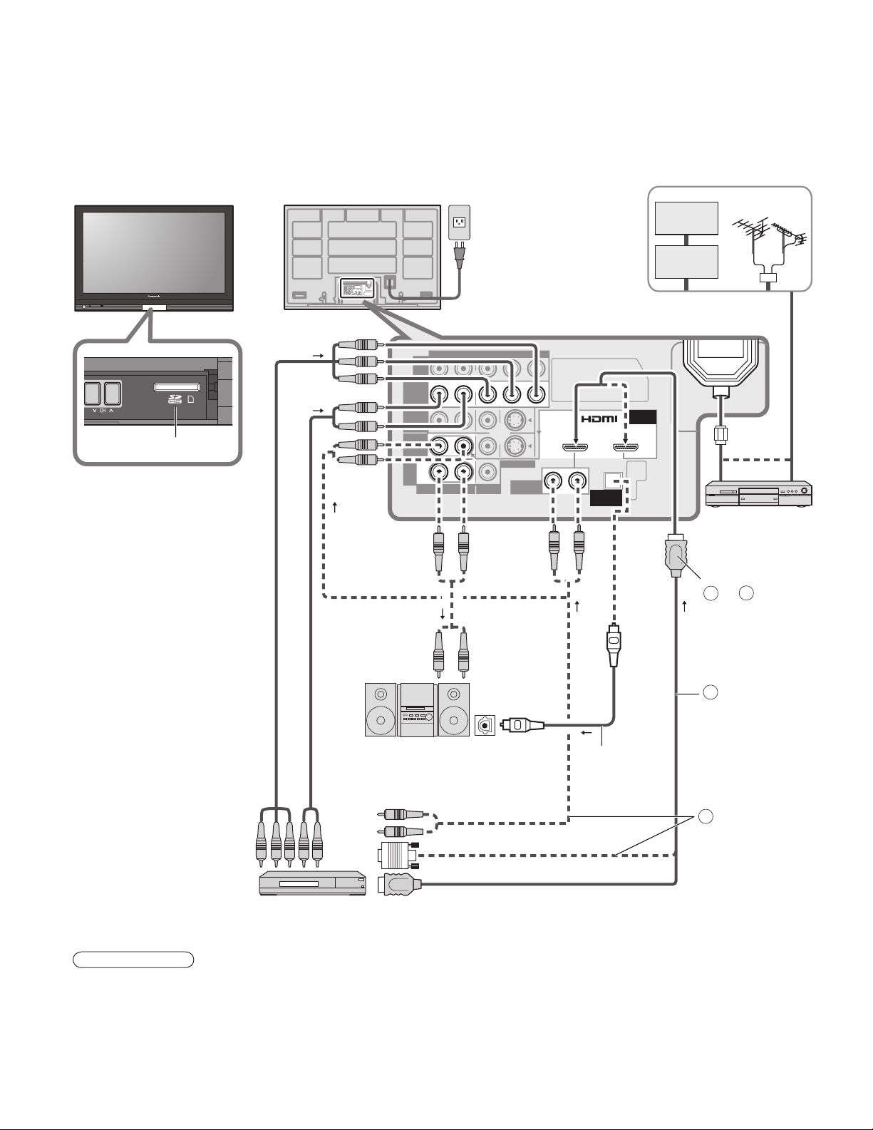
HDMI 2
AUDIO IN
TO
AUDIO
AMP
AV IN 1 AV IN 2
COMPONENT
VIDEO
INPUT
INPUT 1
INPUT 2
AUDIO
AUDIO VIDEO
VIDEO
S VIDEO
PROG
OUT
R
PR PB Y
P
R PB Y
R
R
R
L
L
L
RL
L
R
L
ANTENNA
Cable In
HDMI 1
AUDIO IN
Recommended AV Connections
These diagrams show our recommendations for how to connect the TV unit to your various equipment.
For other connections, consult the instructions for each piece of equipment and the specifications (p. 47).
For additional assistance, please visit our website at: www.panasonic.com
www.panasonic.ca
Front of the TV
SD slot
Back of the TV
AC 120 V
60 Hz
AC Cord
(Connect after all the other
ANTENNA
Cable In
connections are complete.)
or
DIGITAL
AUDIO OUT
Cable TV
Cable Box
or
or
DVD Recorder /
■
VCR
Connect with
A
or B
or
40
To watch DVDs
■
DVD Player/Set Top Box
•
However, audio output can be obtained from
•
Note
The picture and audio input signals connected to a
terminal specified in “Monitor out” (p. 36) cannot be
output from “PROG OUT” terminals.
“DIGITAL AUDIO OUT” terminal.
To prevent howling and image oscillation, set the
“Monitor out” setting when connecting the VCR with
loop-connection. (p. 28, 36)
To listen to the
■
TV through
speakers
A
Amplifier
OPTICAL IN
Optical digital
audio cable
HDMI cable
B
HDMI-DVI
Conversion cable
+ Audio cable
or
When equipment (STB, DVD, etc.) is connected to
•
HDMI or COMPONENT terminals, only audio signals
can be obtained. From the output terminals, no video
signals can be passed.
When receiving digital channel signals, all digital
•
formats are down-converted to composite NTSC
video to be output through the PROG OUT terminals.
Page 41
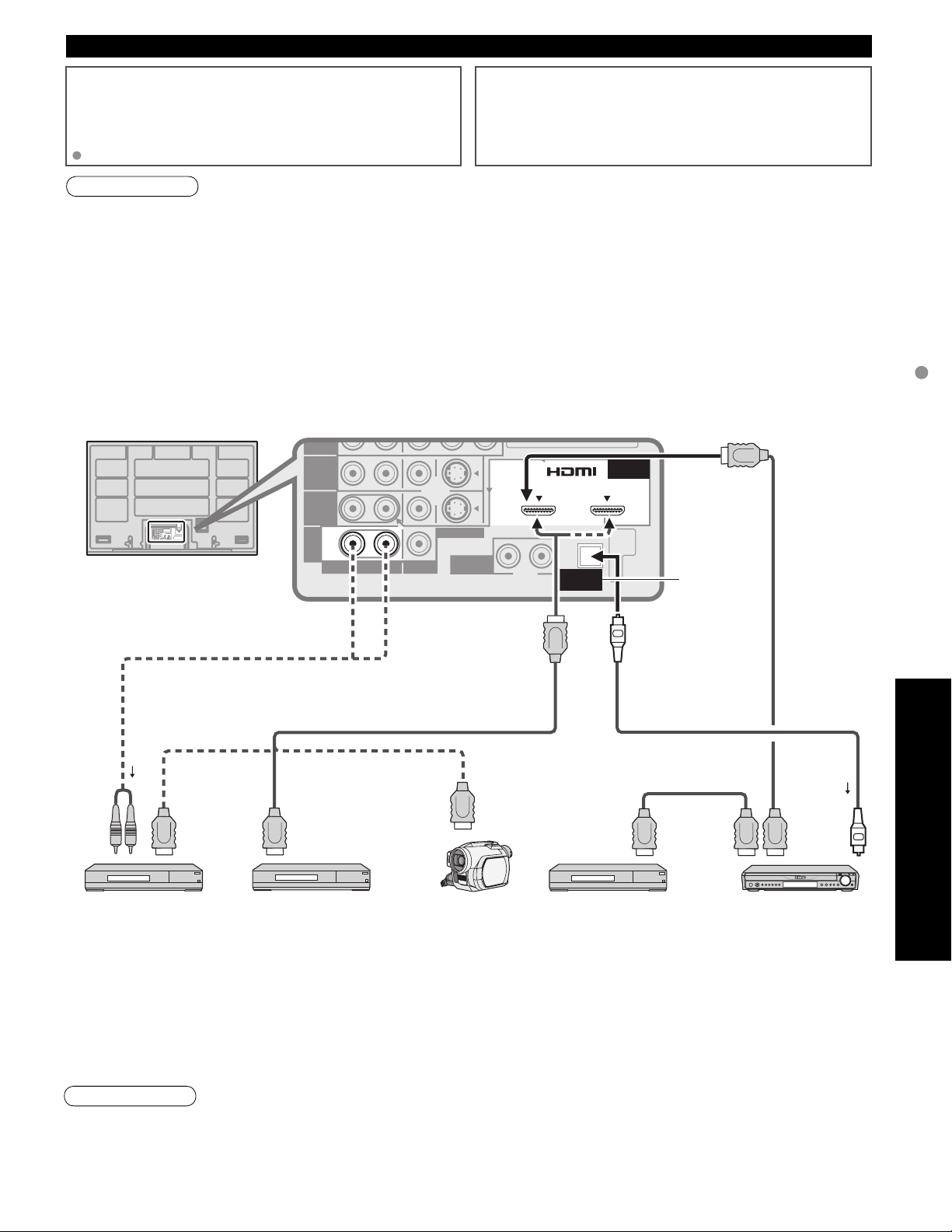
INPUT
EZ SyncTM Connections
Follow the connection diagrams below for HDAVI control of
a single AV piece of equipment such as a Panasonic DIGADVD recorder, RAM theater, or Player theater system.
Refer to page 30-31 for Setup Menu settings and additional
control information.
Optional HDMI and/or optical cables are not provided.
If connection (or setting) of equipment compatible with HDAVI
control is changed, switch the power of this unit Off then On
again while the power of all equipment is On (so that the
unit can correctly recognize the connected equipment) and
check that DIGA, RAM theater, and Player theater playback
operate.
Note
HDMI 1 is recommended.
•
When connecting to HDMI 2, set the input mode to HDMI 2 (p. 24) initially before connecting to HDMI 2. After
connection, confirm the HDMI control functions (p. 30-31).
Connecting this unit to the DIGA, RAM theater, or Player
■
theater
For DIGA: Connect with HDMI cable.
•
For RAM theater and Player theater:
•
Connect with the HDMI and audio cables.
If audio cable is not connected, you cannot listen to the TV
program through the theater system.
R
Back of the TV
L
INPUT 1
R
L
INPUT 2
ANTENNA
Cable In
PROG
OUT
L
R
TO
AUDIO
AMP
L
R
AUDIO VIDEO
PR PB Y
S VIDEO
HDMI 1
AUDIO IN
RL
Connecting this unit to a DVD
■
recorder and AV amp
When using an “EZ Sync” audio-video
amplifier and a compatible DIGA recorder,
use a daisy chain connection as shown
below.
HDMI 2
DIGITAL
AUDIO IN
Digital Audio
out
AV IN 1 AV IN 2
or
AUDIO OUT
Recommended AV Connections
or
or
HDMI cable
HDMI
(AV OUT)
AUDIO
IN
Panasonic RAM theater /
Panasonic Player theater
One AV amp and one DIGA recorder can be operated with this unit.
•
Be sure to connect the AV amp between this unit and the DIGA recorder.
•
Setting of this unit after connection
■
HDMI
(AV OUT)
or
HDMI
(AV OUT)
DIGA
(Panasonic DVD Recorder)
Panasonic
HD Camcorder
(Panasonic DVD Recorder)
HDMI
(AV IN)
HDMI
(AV OUT)
Panasonic AV ampDIGA
After making connections as shown above, set “EZ Sync” (under “EZ Sync setting”) to “On” using the Setup menu.
(p. 30-31).
Note
Individual HDMI equipment may require additional menu settings specific to each model. Please refer to their
•
respective operating instruction manuals.
When audio from other equipment connected to this unit via HDMI is output using “DIGITAL AUDIO OUT” of this
•
unit, the system switches to 2CH audio.
(When connecting to an AV amp via HDMI, you can enjoy higher sound quality.)
Advanced
41
Page 42
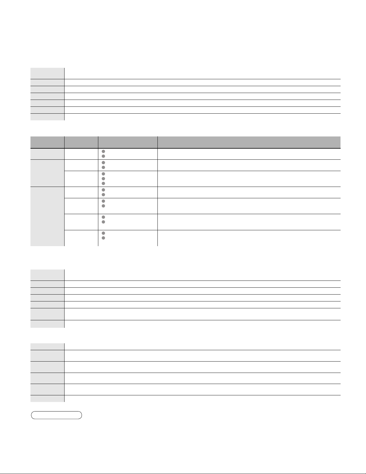
Ratings List for Lock
“V-chip” technology enables you to lock channels or shows according to standard ratings set by the
entertainment industry. (p. 33)
U.S. MOVIE RATINGS (MPAA)
■
NR
G
PG
PG-13
R
NC-17
X
U.S. TV PROGRAMS RATINGS (U. S. TV)
■
Age-based
Group
NR
(Not Rated)
Youth
Guidance
FV: Fantasy/Cartoon Violence. V: Violence S: Sex L: Offensive Language D: Dialogue with sexual content.
NO RATING (NOT RATED) AND NA (NOT APPLICABLE) PROGRAMS. Movie has not been rated or
rating does not apply.
GENERAL AUDIENCES. All ages admitted.
PARENTAL GUIDANCE SUGGESTED. Some material may not be suitable for children.
PARENTS STRONGLY CAUTIONED. Some material may be inappropriate for children under 13.
RESTRICTED. Under 17 requires accompanying parent or adult guardian.
NO ONE 17 AND UNDER ADMITTED.
ADULTS ONLY.
Age-based
Ratings
TV-NR
TV-Y
TV-Y7
TV-G
TV-PG
TV-14
TV-MA
Possible Content
Selections
Viewable
Blocked
Viewable
Blocked
FV Blocked
Viewable
Blocked
Viewable
Blocked
D,L,S,V (all selected)
Any combination of D,
L, S, V
D,L,S,V (all selected)
Any combination of D,
L, S, V
L,S,V (all selected)
Any combination of L,
S, V
Description
Not Rated.
All children. The themes and elements in this program are specifically
designed for a very young audience, including children from ages 2-6.
Directed to older children. Themes and elements in this program may
include mild physical or comedic violence, or may frighten children under
the age of 7.
General audience. It contains little or no violence, no strong language,
and little or no sexual dialogue or situations.
Parental guidance suggested. The program may contain infrequent
coarse language, limited violence, some suggestive sexual dialogue and
situations.
Parents strongly cautioned. This program may contain sophisticated
themes, sexual content, strong language and more intense violence.
Mature audiences only. This program may contain mature themes,
profane language, graphic violence, and explicit sexual content.
42
CANADIAN ENGLISH RATINGS (C. E. L. R.)
■
E
C
C8+
G
PG
14+
18+
CANADIAN FRENCH RATINGS (C. F. L. R.)
■
E
G
8 ans+
13 ans+
16 ans+
18 ans+
Exempt - Exempt programming includes: news, sports, documentaries and other information programming,
talk shows, music videos, and variety programming.
Programming intended for children under age 8. No offensive language, nudity or sexual content.
Programming generally considered acceptable for children 8 years and over. No profanity, nudity or sexual content.
General programming, suitable for all audiences.
Parental Guidance suggested. Some material may not be suitable for children.
Programming contains themes or content which may not be suitable for viewers under the age of 14. Parents are
strongly cautioned to exercise discretion in permitting viewing by pre-teens and early teens.
18+ years old. Programming restricted to adults. Contains constant violence or scenes of extreme violence.
Exempt - Exempt programming.
General - Programming intended for audience of all ages. Contains no violence, or the violence content is minimal
or is depicted appropriately.
8+ General - Not recommended for young children. Programming intended for a broad audience but contains light
or occasional violence. Adult supervision recommended.
Programming may not be suitable for children under the age of 13 - Contains either a few violent scenes or one or
more sufficiently violent scenes to affect them. Adult supervision strongly suggested.
Programming may not be suitable for children under the age of 16 - Contains frequent scenes of violence or intense
violence.
Programming restricted to adults. Contains constant violence or scenes of extreme violence.
Caution
The V-Chip system that is used in this set is capable of blocking “NR” programs (non rated, not applicable and
•
none) as per FCC Rules Section15.120(e)(2). If the option of blocking “NR” programs is chosen “unexpected and
possibly confusing results may occur, and you may not receive emergency bulletins or any of the following types of
programming:”
• Emergency Bulletins (Such as EAS messages, weather warnings and others)
• Locally originated programming • News • Political • Public Service Announcements • Religious • Sports • Weather
Page 43
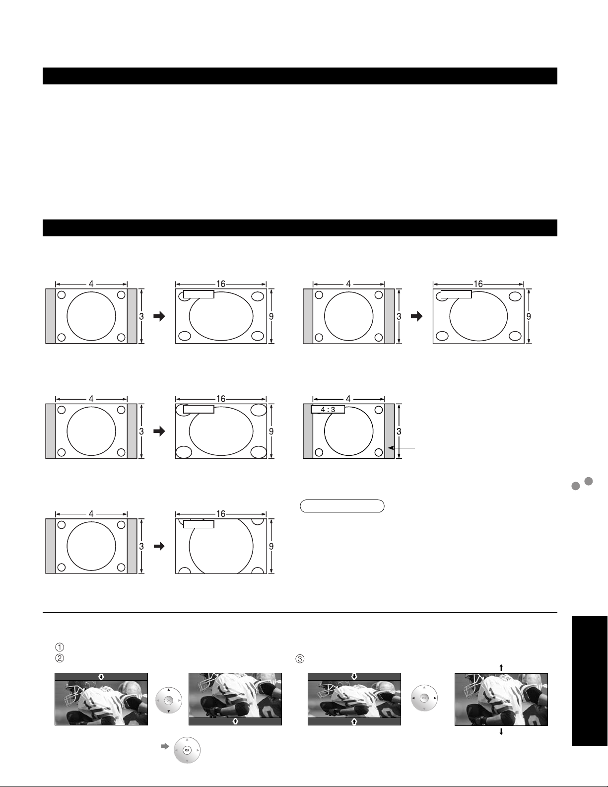
Technical Information
Closed Caption (CC)
For viewing Closed Caption of digital broadcasting, set the aspect ratio to FULL.
•
(If viewing with H-FILL, JUST, ZOOM or 4:3, characters will be cut off.)
The Closed Caption is not displayed when you use HDMI connection.
•
If analog connected equipment is used for displaying or recording, Closed Caption (CC) should be set On/Off on
•
the connected equipment.
The CC mode setting of the TV will not affect the analog input.
If a digital program is being output in analog format, the CC data will also be output in analog format.
If digital connected equipment is used for input, CC should be set On on either the connected equipment or the TV.
If CC is set On on both the connected equipment and the TV, captions from each unit will overlap.
Aspect Ratio
Lets you choose the aspect depending on the format of the received signal and your preference. (p. 21)
(e.g.: in case of 4:3 image)
•
FULL
FULL
•
JUST
JUST
Enlarges the 4:3 image horizontally to the screen’s side edges.
(Recommended for anamorphic picture)
H-FILL
•
H-FILL
Enlarges the 4:3 image horizontally to the screen’s side edges.
The side edges of the image are cut off.
ZOOM
•
ZOOM
Enlarges the 4:3 image to the entire screen.
(Recommended for Letter Box)
Zoom adjust
•
Vertical image position and size can be adjusted in “ZOOM”.
Select “Zoom adjust” on the “Picture” menu. (p. 26-27)
V-position: Vertical position adjustment V-size: Vertical size adjustment
Stretches to justify the 4:3 image to the four corners of the
screen.
(Recommended for normal TV broadcast)
4:3
•
Standard
(Note that “Image retention” of the side bar may occur from
displaying it for a long time.)
Note
480i (4:3), 480i (16:9), 480p (4:3), 480p (16:9):
•
FULL, JUST, 4:3 or ZOOM
1080p / 1080i / 720p:
•
FULL, H-FILL, JUST, 4:3 or ZOOM
When the signal is 720p/1080i/1080p, the aspect mode
•
automatically defaults to Full after turning off the TV,
after changing input mode, or after changed signal
resolution other than 720p/1080i/1080p.
Side bar
Technical Information
Ratings List for Lock
FAQs, etc.
To reset the aspect ratio (OK)
•
43
Page 44
Technical Information (Continued)
Data format for SD Card browsing
Photo: Still images recorded with digital still cameras compatible with JPEG files of DCF* and EXIF** standards
Data format: Baseline JPEG (Sub-sampling: 4:4:4, 4:2:2 or 4:2:0)
Max. number of files: 9,999
Image resolution: 160 x 120 to 10,000,000
* DCF (Design rule for camera file system): A Japan Electronics and Information Technology Industries Association’s standard
** EXIF (Exchangeable Image File Format)
Caution
A JPEG image modified with a PC may not be displayed.
•
Partly degraded files might be displayed at a reduced resolution.
•
Note
Folder structure viewed in PC
•
DCIM
100_PANA
Created automatically
3-digit folder number + 5-digit arbitrary characters
P1000001.JPG
P1000002.JPG
P1000003.JPG
P1000004.JPG
The folder and file names may be different depending on the digital camera used.
•
For the suitable SD Memory Cards, please confirm the latest information on the following website.
•
http://panasonic.co.jp/pavc/global/cs (This site is in English only)
Message Meaning
Is memory card in?
No file
Cannot read file
Cannot display image due to
incorrect ID data.
Cannot display image on SD card.
4-digit arbitrary characters + 4-digit file number
Usable characters: 1-byte “a to z”, “A to Z”, “0 to 9,” and “_”
•
SD Card warning messages
The card is not inserted.
•
The card has no data or this type of data is not supported.
•
The file is broken or unreadable.
•
The TV does not support the format.
•
GalleryPlayer warning messages
There is a problem with your TV decoder.
•
If this message appears, please contact Panasonic Service Center for
•
assistance.
Refer to page 50, 52 (Limited Warranty), page 51 (Customer Services Directory)
There is a problem with the data.
•
Check the data inside the SD card.
44
Cautions in handling SD Card:
Do not remove the card while the unit is accessing data (this can damage card or unit).
•
Do not touch the terminals on the back of the card.
•
Do not subject the card to a high pressure or impact.
•
Insert the card in the correct direction (otherwise, card may be damaged).
•
Electrical interference, static electricity, or erroneous operation may damage the data or card.
•
Back up the recorded data at regular intervals in case of deteriorated or damaged data or erratic
•
operation of the unit. (Panasonic is not liable for any deterioration or damage of recorded data.)
DIGITAL AUDIO OUT terminals
You can enjoy your home theater by connecting a Dolby Digital (5.1 channel) decoder and “Multi Channel” amplifier to the DIGITAL AUDIO OUT terminals.
Caution
Depending on your DVD player and DVD-Audio software the copyright protection function may operate and disable optical output.
•
External speakers cannot be connected directly to PROG OUT terminals.
•
When an ATSC channel is selected, the output from the DIGITAL AUDIO OUT jack will be Dolby Digital. When an NTSC
•
channel is selected, the output will be PCM.
Page 45
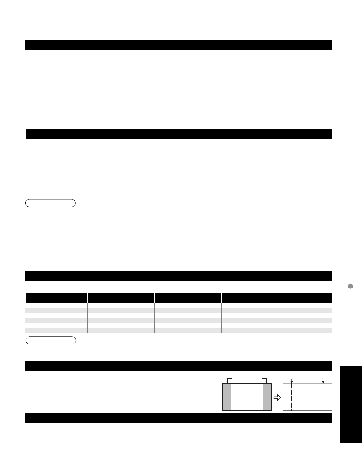
EZ SyncTM “HDAVI ControlTM”
HDMI connections to some Panasonic equipment allow you to interface automatically. (p. 30)
This function may not work normally depending on the equipment condition.
•
The equipment can be operated by other remote controls with this function on even if TV is in Standby mode.
•
Image or sound may not be available for the first few seconds when the playback starts.
•
Image or sound may not be available for the first few seconds when Input mode is switched.
•
Volume function will be displayed when adjusting the volume of the equipment.
•
If you connect the same kind of equipment at once (for example: one DIGA to HDMI 1 / another DIGA to HDMI 2), EZ SyncTM is
•
available for the terminal with the smaller number.
If you connect the equipment that has “HDAVI Control 2” function to the TV with HDMI cable, the sound from DIGITAL AUDIO
•
OUT terminal can be output as multi channel surround.
“HDAVI Control 2” is the newest standard (current as of February, 2007) for Panasonic’s HDAVI Control compatible equipment.
•
This standard is compatible with Panasonic’s conventional HDAVI equipment.
HDMI connection
HDMI (high-definition multimedia interface) allows you to enjoy high-definition digital images and high-quality sound by connecting
the TV unit and the devices.
HDMI-compatible equipment (*1) with an HDMI or DVI output terminal, such as a set-top box or a DVD player, can be connected
to the HDMI connector using an HDMI compliant (fully wired) cable.
HDMI is the world’s first complete digital consumer AV interface complying with a non-compression standard.
•
If the external equipment has only a DVI output, connect to the HDMI terminal via a DVI to HDMI adapter cable (*2).
•
When the DVI to HDMI adapter cable is used, connect the audio cable to the audio input terminal.
•
Audio settings can be made on the “HDMI 1 in” or “HDMI 2 in” menu screen. (p. 26)
•
Applicable audio signal sampling frequencies (L.PCM): 48 kHz, 44.1 kHz, 32 kHz
(*1): The HDMI logo is displayed on an HDMI-compliant device.
Caution
(*2): Enquire at your local digital equipment retailer shop.
Use with a PC is not assumed.
•
All signals are reformatted before being displayed on the screen.
•
If the connected device has an aspect adjustment function, set the aspect ratio to “16:9”.
•
These HDMI connectors are “type A”.
•
These HDMI connectors are compatible with HDCP (High-Bandwidth Digital Content Protection) copyright protection.
•
A device having no digital output terminal may be connected to the input terminal of either “COMPONENT”, “S VIDEO”, or
•
“VIDEO” to receive analog signals.
The HDMI input terminal can be used with only the following image signals: 480i, 480p, 720p, 1080i and 1080p.
•
Match the output setting of the digital device.
For details of the applicable HDMI signals, see below.
•
Input signals that can be displayed
* Mark: Applicable input signal for Component (Y, PB, PR) and HDMI
horizontal
525 (480) / 60i 15.73 59.94
525 (480) /60p 31.47 59.94
750 (720) /60p 45.00 59.94
1,125 (1,080) /60i 33.75 59.94
1,125 (1,080)/60p 67.43 59.94
1,125 (1,080)/60p 67.50 60.00
Note
Signals other than those shown above may not be displayed properly.
•
The above signals are reformatted for optimal viewing on your display.
•
Do not display a picture in 4:3 mode for an extended period, as this can cause “Image
retention” to remain on either or both sides of the display field.
To reduce the risk of such “
The side bar may flash (alternate black/white) depending on the picture. Using
•
Cinema mode will reduce such flashing (See below).
Vivid (default): Provides enhanced picture contrast and sharpness for viewing in a well-lit room.
•
Standard: Recommended for normal viewing conditions with subdued room lighting.
•
Cinema: For watching movies in a darkened room. It provides a soft, film-like picture.
•
Custom (Photo): Customizes each item according to your taste.
•
Photo is displayed in JPEG menu.
frequency (kHz)
Image retention”
, change the brightness of the side bars.
Picture mode
vertical
frequency (Hz)
Side Bar
COMPONENT HDMI
Side Bar
4:3
Screen
Display
Technical Information
**
**
**
**
*
*
Image retention
FAQs, etc.
45
Page 46

Maintenance
First, unplug the Power cord plug from the wall outlet.
Display panel
The front of the display panel has been specially treated. Wipe the panel surface gently using only a cleaning cloth or
a soft, lint-free cloth.
If the surface is particularly dirty, soak a soft, lint-free cloth in diluted neutral detergent (1 part detergent diluted by
•
100 times the amount of water) and then wring the cloth to remove excess liquid. Use this cloth to wipe the surface
of the display panel, then wipe it evenly with a dry cloth of the same type until the surface is dry.
Do not scratch or hit the surface of the panel with fingernails or other hard objects. Furthermore, avoid contact
•
with volatile substances such as insect sprays, solvents, and thinner; otherwise, the quality of the surface may be
adversely affected.
Cabinet
If the cabinet becomes dirty, wipe it with a soft, dry cloth.
If the cabinet is particularly dirty, soak the cloth in a weak detergent solution and then wring the cloth dry.
•
Use this cloth to wipe the cabinet and then wipe it dry with a dry cloth.
Do not allow any detergent to come into direct contact with the surface of the Plasma TV.
•
If water droplets get inside the unit, operating problems may result.
Avoid contact with volatile substances such as insect sprays, solvents, and thinner; otherwise, the quality of the
•
cabinet surface may be adversely affected or the coating may peel off. Furthermore, do not leave it for long periods
in contact with articles made from rubber or PVC.
Pedestal
Cleaning
•
Wipe the surfaces with a soft, dry cloth. If the unit is particularly dirty, clean it using a cloth soaked with water to
which a small amount of neutral detergent has been added and then wipe with a dry cloth.
Do not use products such as solvents, thinner, or household wax for cleaning, as they can damage the surface
coating. (If using a chemically-treated cloth, follow the instructions supplied with the cloth.)
Do not attach sticky tape or labels, as they can make the surface of the pedestal dirty. Do not allow long-term
•
contact with rubber, vinyl products, or the like. (Doing so will cause deterioration.)
46
Page 47
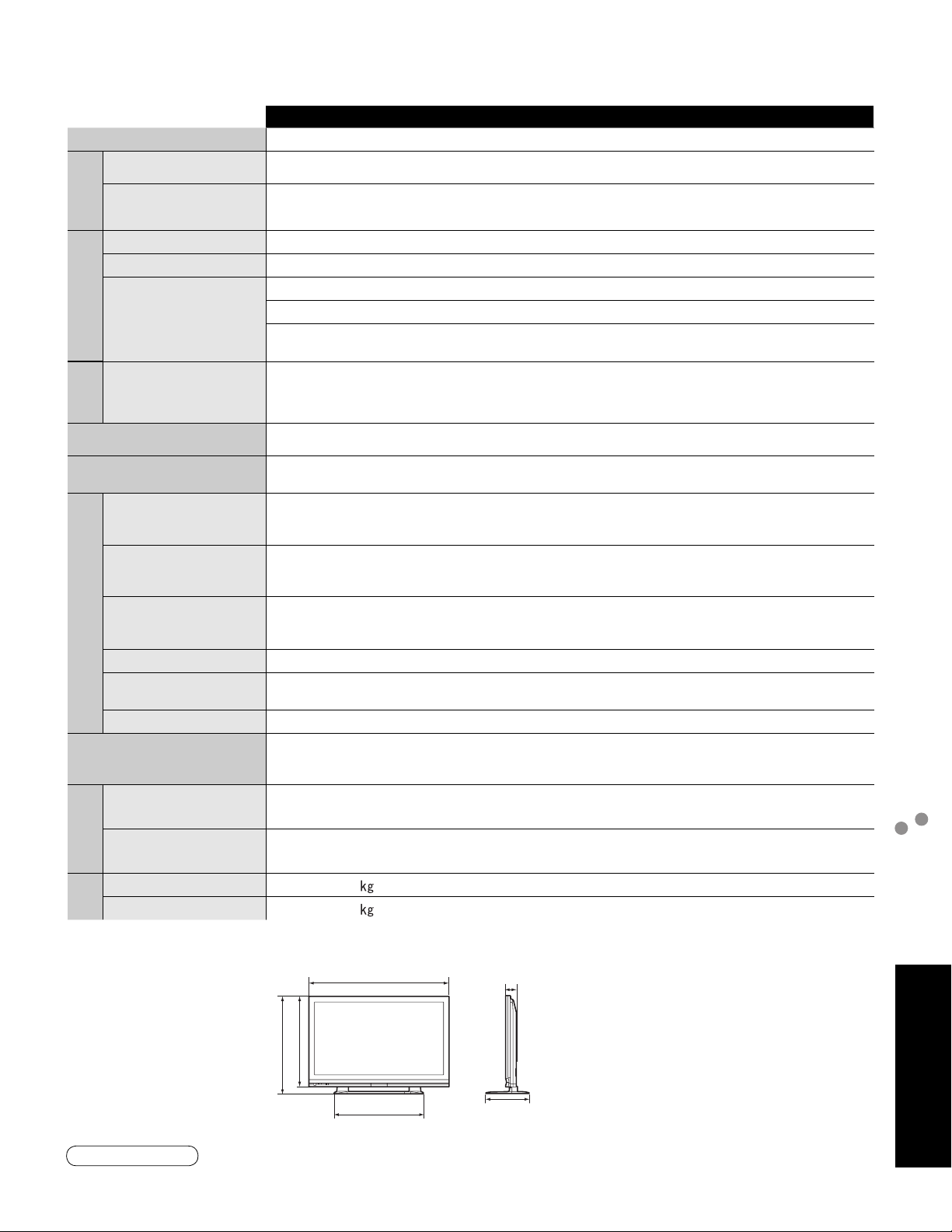
Specifications
Power Source AC 120 V, 60 Hz
Power
Consumption
Maximum 653 W
Standby condition 0.2 W
Plasma Display
panel
Drive method AC type
Aspect Ratio 16:9
Visible screen size
(W × H × Diagonal)
(No. of pixels)
Sound
Audio Output 20 W [ 10 W + 10 W ] ( 10 % THD )
58 ” (Diagonal)
50.6 ” × 28.4 ” × 58.1 ”
1,049,088 (1,366 (W) × 768 (H))
[4,098 × 768 dots]
(1,287 mm × 723 mm × 1,476 mm)
TH-58PE75U
Channel Capability
(Digital/Analog)
Operating Conditions
INPUT 1-2
Connection Terminals
COMPONENT VIDEO
INPUT 1-2
HDMI 1-2
AUDIO IN
Card slot SD CARD slot × 1
AV PROG. OUT
DIGIT AL AUDIO OUT PCM / Dolby Digital, Fiber Optic
FEATURES
( W × H × D )
Dimensions
Including pedestal 55.2 ” × 38.3 ” × 17.0 ”
TV Set only 55.2 ” × 35.9 ” × 4.0 ”
Mass
Including pedestal 130.1 lb. (59 )
TV Set only 123.5 lb. (56
VHF/ UHF: 2 - 69, CATV: 1 - 135
Temperature: 32 °F – 104 °F (0 °C – 40 °C)
Humidity: 20 % – 80 % RH (non-condensing)
VIDEO: RCA PIN Type × 1 1.0 V [p-p] (75 Ω)
S-VIDEO: Mini DIN 4-pin Y: 1.0 V [p-p] (75 Ω) C: 0.286 V [p-p] (75 Ω)
AUDIO L-R: RCA PIN Type × 2 0.5 V [rms]
Y: 1.0 V [p-p] (including synchronization)
B, PR: ±0.35 V [p-p]
P
AUDIO L-R: RCA PIN Type × 2 0.5 V [rms]
TYPE A Connector × 2
This TV supports “HDAVI Control 2” function.
•
AUDIO L-R: RCA PIN Type × 2 0.5 V [rms]
VIDEO: RCA PIN Type × 1 1.0 V [p-p] (75 Ω)
AUDIO L-R: RCA PIN Type × 2 0.5 V [rms]
3D Y/C FILTER
CLOSED CAPTION V-Chip
Photo viewer HDAVI Control 2
)
(1,401 mm × 973 mm × 430 mm)
(1,401 mm × 910 mm × 100 mm)
Specifications
Maintenance
[TH-58PE75U]
55.2” (1,401 mm) 4.0 ” (100 mm)
35.9 ” (910 mm)
38.3 ” (973 mm)
35.0 ” (887 mm)
17.0 ” (430 mm)
Note
Design and Specifications are subject to change without notice. Mass and Dimensions shown are approximate.
•
FAQs, etc.
47
Page 48
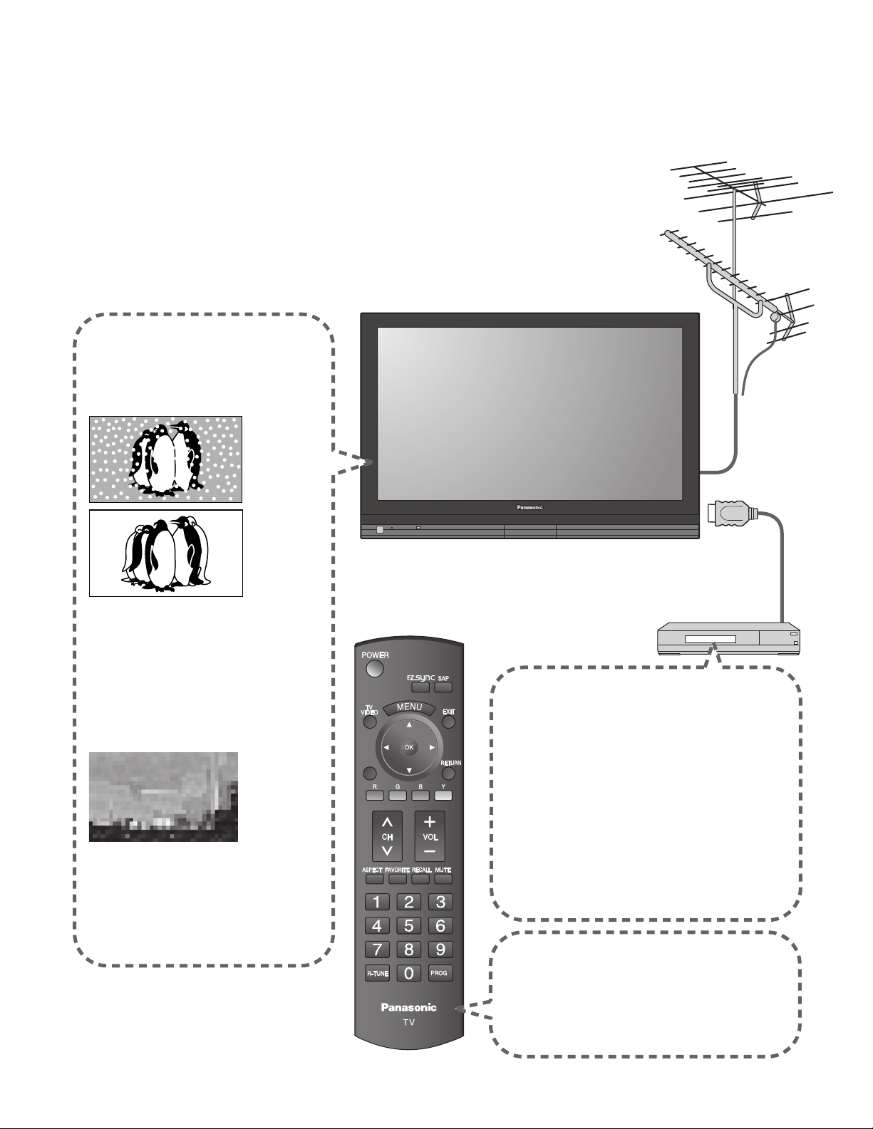
FAQ
-
SUB
MENU
-
Before requesting service or assistance, please follow these simple guides to resolve the problem.
If the problem still persists, please contact your local Panasonic dealer or Panasonic Service Center for assistance.
For details (p. 51, 52)
For additional assistance, please contact us via the website at:
www.panasonic.com/contactinfo
www.panasonic.ca
White spots or
shadow images
(noise)
Check the position, direction,
•
and connection of the aerial.
Interference or
frozen digital
channels
(intermittent sound)
Change the direction of antenna
•
for digital channels.
Check “Signal meter” (p. 35).
•
If the signal is weak, check the
antenna and consult your local
dealer.
SUB
MENU
Pictures from external
equipment are distorted
when the unit is
connected via HDMI
Is the HDMI cable connected properly?
•
(p. 40-41)
Turn Off the TV unit and equipment, then
•
turn them On again.
Check an input signal from the equipment.
•
(p. 45)
Use equipment compliant with
•
EIA/CEA-861/861B.
The remote control does
not work
Are the batteries installed correctly? (p. 6)
•
Has the battery run down?
•
48
Page 49
If there is a problem with your TV, please refer to the table below to determine the symptoms, then carry out the
suggested check. If this does not solve the problem, please contact your local Panasonic dealer, quoting the model
number and serial number (both found on the rear of the TV).
Problem Actions
The function to prevent “Image retention” is activated.
•
“Press any key to return”
moves on the screen
One spot remains dark
Chaotic image, noisy
Screen
(Not a faulty symptom)
The screen saver is activated if the TV unit is not operated for
a certain time in SD mode.
“Image retention” (p. 5)
A pixel or luminescent spot can occasionally
•
be missing in plasma displays.
(Not a faulty symptom)
Check nearby electrical products
•
(car, motorcycle, fluorescent lamp).
No image can be
displayed
Only spots are displayed
instead of images
Neither image nor
sound is produced
Black Box appears
No sound is produced
Sound
Sound is unusual
Check Picture menu (p. 26)
•
Check the channel settings. (p. 34)
•
Check the antenna cables.
•
Is the AC power cord plugged into the outlet?
•
Is the TV unit turned On?
•
Check Picture menu (p. 26) and volume.
•
Change settings of Closed Caption (CC). (p. 36)
•
Are the speakers’ cables connected correctly? (p. 40)
•
Is “Sound Mute” active? (p. 17)
•
Is the volume set to the minimum?
•
Is “Speaker output” set to “Off”? (p. 26)
•
Change “SAP” settings. (p. 20)
•
Check “HDMI 1 in” or “HDMI 2 in” settings. (p. 26)
•
Set “SAP” setting to “Stereo” or “Mono.”
•
Check the HDMI device connected to the unit.
•
Set the audio setting of the HDMI device to
•
“Linear PCM.”
If digital sound connection has a problem,
•
select analog sound connection.
Frequently Asked Questions
FAQs, etc.
49
Page 50

Limited Warranty (for U.S.A.)
50
PANASONIC CONSUMER ELECTRONICS COMPANY,
DIVISION OF
PANASONIC CORPORATION OF NORTH AMERICA
One Panasonic Way
Secaucus, New Jersey 07094
PANASONIC SALES COMPANY,
DIVISION OF
PANASONIC PUERTO RICO, INC.
Ave. 65 de Infanteria, Km. 9.5
San Gabriel Industrial Park
Carolina, Puerto Rico 00985
Panasonic Color Television
Limited Warranty
Limited Warranty Coverage
If your product does not work properly because of a defect in materials or workmanship, Panasonic Consumer
Electronics Company or Panasonic Puerto Rico, Inc. (collectively referred to as “the warrantor”) will, for the length of
the period indicated on the chart below, which starts with the date of original purchase (“Limited Warranty period”),
at its option either (a) repair your product with new or refurbished parts, or (b) replace it with a new or a refurbished
product. The decision to repair or replace will be made by the warrantor.
CATEGORIES
PLASMA DISPLAY 1 (ONE) YEAR 1 (ONE) YEAR
During the “Labor” Limited Warranty period there will be no charge for labor. During the “Parts” Limited Warranty
period, there will be no charge for parts.
You must carry-in your product or arrange for in-home service during the Limited Warranty period. If nonrechargeable batteries are included, they are not warranted. This Limited Warranty only applies to products
purchased and serviced in the United States or Puerto Rico. This Limited Warranty is extended only to the original
purchaser and only covers product purchased as new. A purchase receipt or other proof of the original purchase date
is required for Limited Warranty service.
In-Home or Carry-in Service
For In-Home or Carry-In Service in the United States call 1-888-VIEW-PTV(1-888-843-9788).
For assistance in Puerto Rico call Panasonic Puerto Rico, Inc. (787)-750-4300 or fax (787)-768-2910.
In-Home service requires clear, complete and easy access to the product by the authorized servicer and does
not include removal or re-installation of an installed product. It is possible that certain in-home repairs will not be
completed in-home, but will require that the product, or parts of the product, be removed for shop diagnosis and/or
repair and then returned.
Limited Warranty Limits And Exclusions
This Limited Warranty ONLY COVERS failures due to defects in materials or workmanship, and DOES NOT COVER
normal wear and tear or cosmetic damage, nor does it cover markings or retained images on the picture tube
resulting from viewing fixed images (including, among other things, letterbox pictures on standard 4:3 screen TV’s,
or non-expanded standard 4:3 pictures on wide screen TV’s, or onscreen data in a stationary and fixed location).
The Limited Warranty ALSO DOES NOT COVER damages which occurred in shipment, or failures which are caused
by products not supplied by the warrantor, or failures which result from accidents, misuse, abuse, neglect, bug
infestation, mishandling, misapplication, alteration, faulty installation, set-up adjustments, misadjustment of consumer
controls, improper maintenance, power line surge, lightning damage, modification, or commercial use (such as in a
hotel, office, restaurant, or other business), rental use of the product, service by anyone other than a Factory Service
Center or other Authorized Servicer, or damage that is attributable to acts of God.
THERE ARE NO EXPRESS WARRANTIES EXCEPT AS LISTED UNDER “LIMITED WARRANTY COVERAGE”.
THE WARRANTOR IS NOT LIABLE FOR INCIDENTAL OR CONSEQUENTIAL DAMAGES RESULTING FROM
THE USE OF THIS PRODUCT, OR ARISING OUT OF ANY BREACH OF THIS LIMITED WARRANTY. (As
examples, this excludes damages for lost time, cost of having someone remove or re-install an installed unit if
applicable, or travel to and from the servicer. The items listed are not exclusive, but are for illustration only.) ALL
EXPRESS AND IMPLIED WARRANTIES, INCLUDING THE LIMITED WARRANTY OF MERCHANTABILITY, ARE
LIMITED TO THE PERIOD OF THE LIMITED WARRANTY.
Some states do not allow the exclusion or limitation of incidental or consequential damages, or limitations on how
long an implied Limited Warranty lasts, so the exclusions may not apply to you.
This Limited Warranty gives you specific legal rights and you may also have others rights which vary from state
to state. If a problem with this product develops during or after the Limited Warranty period, you may contact your
dealer or Service Center. If the problem is not handled to your satisfaction, then write to the warrantor’s Consumer
Affairs Department at the addresses listed for the warrantor.
PARTS AND SERVICE (INCLUDING COST OF AN IN-HOME SERVICE CALL, WHERE APPLICABLE) WHICH
ARE NOT COVERED BY THIS LIMITED WARRANTY ARE YOUR RESPONSIBILITY.
ALL PARTS EXCEPT
GLASS PANEL OR CRT
LABOR GLASS PANEL OR CRT
GLASS PANEL - 2 (TWO)
YEARS
GLASS PANEL
OR
CRT LABOR
1 (ONE) YEAR IN-HOME OR CARRY-IN
SERVICE
Page 51

Customer Services Directory
Customer Services Directory
Obtain Product Information and Operating Assistance; locate your nearest Dealer or Service Center;
purchase Parts and Accessories; or make Customer Service and Literature requests by visiting our Web
Site at:
http://www.panasonic.com/consumersupport
or, contact us via the web at:
http://www.panasonic.com/contactinfo
You may also contact us directly at:
1-888-VIEW-PTV (843-9788)
Monday-Friday 9 am-9 pm; Saturday-Sunday 10 am-7 pm, EST.
For hearing or speech impaired TTY users, TTY: 1-877-833-8855
■
Accessory Purchases
Purchase Parts, Accessories and Instruction Books on line for all Panasonic Products by visiting our Web
Site at:
http://www.pstc.panasonic.com
or, send your request by E-mail to:
You may also contact us directly at:
1-800-332-5368 (Phone) 1-800-237-9080 (Fax Only) (Monday - Friday 9 am to 8 pm, EST.)
Panasonic Service and Technology Company
20421 84th Avenue South,
Kent, WA 98032
(We Accept Visa, MasterCard, Discover Card, American Express, and Personal Checks)
For hearing or speech impaired TTY users, TTY: 1-866-605-1277
■
(for U.S.A.)
Customer Services Directory (for U.S.A.)
Limited Warranty (for U.S.A.)
Service in Puerto Rico
Panasonic Puerto Rico, Inc.
Ave. 65 de Infantería, Km. 9.5, San Gabriel Industrial Park,
Carolina, Puerto Rico 00985
Phone (787)750-4300, Fax (787)768-2910
FAQs, etc.
51
Page 52
Limited Warranty (for Canada)
Panasonic Canada Inc.
PANASONIC PRODUCT - LIMITED WARRANTY
Panasonic Canada Inc. warrants this product to be free from defects in material and workmanship and agrees to
remedy any such defect for a period as stated below from the date of original purchase.
Plasma TV / Monitor In-home service One (1) year, parts (including Plasma Panel) and labour.
LCD TV (26 in & over) In-home service One (1) year, parts (including LCD Panel) and labour.
LCD TV (25 in & under) Carry-in service only One (1) year, parts (including LCD Panel) and labour.
In-home Service will be carried out only to locations accessible by roads and within 50 km of an authorized
Panasonic service facility.
LIMIT ATIONS AND EXCLUSIONS
This warranty does not apply to products purchased outside Canada or to any product which has been improperly
installed, subjected to usage for which the product was not designed, misused or abused, damaged during shipping,
or which has been altered or repaired in any way that affects the reliability or detracts from the performance, nor
does it cover any product which is used commercially. Dry cell batteries are also excluded from coverage under this
warranty.
This warranty is extended to the original end user purchaser only. A purchase receipt or other proof of date of original
purchase is required before warranty service is performed.
THIS EXPRESS, LIMITED WARRANTY IS IN LIEU OF ALL OTHER WARRANTIES, EXPRESS OR IMPLIED,
INCLUDING ANY IMPLIED WARRANTIES OF MERCHANTABILITY AND FITNESS FOR A PARTICULAR
PURPOSE. IN NO EVENT WILL PANASONIC CANADA INC. BE LIABLE FOR ANY SPECIAL, INDIRECT OR
CONSEQUENTIAL DAMAGES.
In certain instances, some jurisdictions do not allow the exclusion or limitation of incidental or consequential
damages, or the exclusion of implied warranties, so the above limitations and exclusions may not be applicable.
In-home service requires clear, complete and easy access to the product by the Authorized Servicentre and does not
include removal or re-installation of an installed product. If removal is required to service the product, it will be at the
discretion of the Servicentre and in no event will Panasonic Canada Inc. or the Servicentre be liable for any special,
indirect or consequential damages.
WARRANTY SERVICE
For product operation and information assistance, please contact:
Our Customer Care Centre: Telephone #: (905) 624-5505
1-800 #: 1-800-561-5505
Fax #: (905) 238-2360
Email link: “Customer support” on www.panasonic.ca
FOR PRODUCT REPAIRS, please locate your nearest Authorized Servicentre at www.panasonic.ca:
Link: “Servicentres™ locator” under “Customer support”
IF YOU SHIP THE PRODUCT TO A SERVICENTRE
Carefully pack and send prepaid, adequately insured and preferably in the original carton.
Include details of the defect claimed, and proof of date of original purchase.
52
Page 53

Note
Limited Warranty (for Canada)
FAQs, etc.
53
Page 54

Note
Page 55

Note
Page 56

Customer’s Record
The model number and serial number of this product can be found on its back cover. You should note this serial
number in the space provided below and retain this book, plus your purchase receipt, as a permanent record of
your purchase to aid in identification in the event of theft or loss, and for Warranty Service purposes.
Model Number Serial Number
Anotación del cliente
El modelo y el número de serie de este producto se encuentran en su panel posterior. Deberá anotarlos en el
espacio provisto a continuación y guardar este manual, más el recibo de su compra, como prueba permanente de
su adquisición, para que le sirva de ayuda al identificarlo en el caso de que le sea sustraído o lo pierda, y también
para disponer de los servicios que le ofrece la garantía.
Modelo Número de serie
Panasonic Consumer Electronics
Company,
Division of Panasonic Corporation
of North America
Panasonic Puerto Rico, Inc.
Ave. 65 de Infanteria, Km. 9.5
San Gabriel Industrial Park
Carolina, Puerto Rico 00985
One Panasonic Way, Secaucus
New Jersey 07094 U.S.A.
©
2007 Panasonic Corporation of North America. All Rights Reserved.
©
2007 Panasonic Corporation of North America. Todos los Derechos Reservados.
Panasonic Canada Inc.
5770 Ambler Drive
Mississauga, Ontario
L4W 2T3 CANADA
Printed in U.S.A.
Impreso en EE.UU.
 Loading...