

Panasonic SVMP-720-VSG, SVMP-730-VSG Service manual
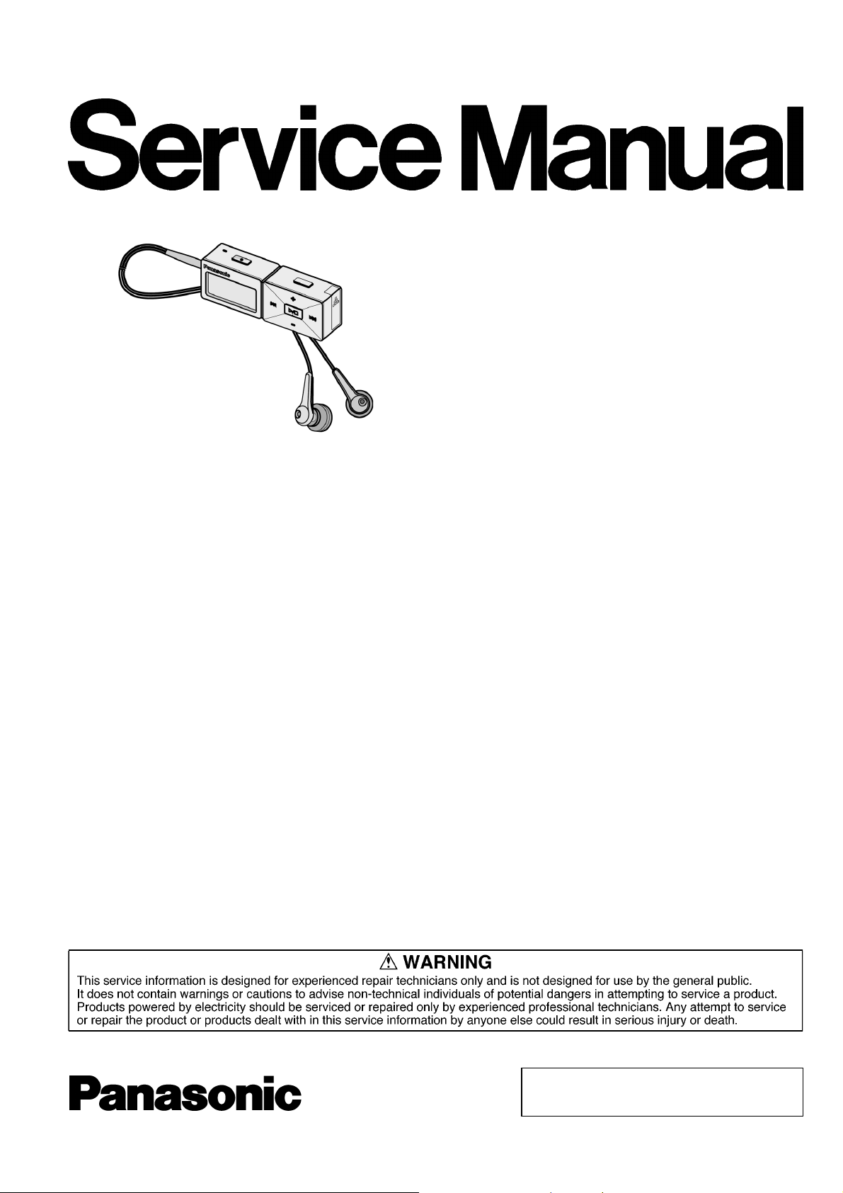
Digital Audio Player
SV-MP720VSG
SV-MP730VSG
Colour
(K).................... Black Type
(S).................... Silver Type
(W)....................White Type
TD0508048C3
Specifications
Memory size: SV-MP720V: 512 MB
SV-MP730V: 1 GB
Supported sampling frequency:
Supported bit-rates:
No. of channels:
Frequency response: 20 Hz to 20,000 Hz (+0dB, -6dB)
Mic S/N:
Radio Frequency range (FM):
Output:
Power supply: DC 1.2V (one rechargeable
MP3; 32 kHz, 44.1 kHz,and 48
kHz
WMA; 8 kHz to 44.1 kHz
MP3; 8 kbps to 320 kbps (128
kbps is recommend)
WMA; 32 kbps to 192 kbps (96
kbps is recommend)
Stereo, 2 channels (MUSIC, FM
RADIO)
Mono, 1 channel (IC RECORDER)
(MUSIC)
300 Hz to 4,300 Hz (IC
RECORDER, HQ mode)
30 dB (IC RECORDER,HQ mode)
87.90 MHz to 107.90 MHz (200
kHz steps)
87.50 MHz to 108.00 MHz (50/100
kHz steps)
4.5 mW + 4.5 mW (16Ω,M3 jack)
battery)
Approximate play times: 10 hours (MUSIC),
5 hours (FM RADIO)
Approximate recording times:
Cabinet dimensions (WxHxD):
Mass:
AC adaptir input: AC110V ~ 240V,50 Hz/ 60 Hz
Power consumption in standby
mode: 0.1W
· Specifications are subject to change without notice.
· The play times shown depend on operating conditions.
· Mass and dimensions are approximate.
· MB means one million bytes. Useable capacity may be less.
· GB means one billion bytes. Useable capacity will be less.
· This product is compatible with the following character code. The
display may not appear correctly with other character codes.
· When the supplied rechargeable battery is fully charged.
· The play time shown is when the bit rate is 128 kpbs (MP3), EQ
is set to NORMAL, volume is 11 and the backlight is not used.
9 hours (IC RECORDER, HQ
mode)
5 hours (FM RADIO)
70.0 x 22.2 x 14.0 mm
36.2g with battery
23.5g without battery
© 2005 Matsushita Electric TAIWAN Industrial Co.,
Ltd. All rights reserved. Unauthorized copying and
distribution is a violation of law.
SV-MP720VSG / SV-MP73 0VSG
CONTENTS
Page Page
1 Accessories 2
2 Supply of Rechargeable Battery as Replacement Parts
3 Caution in Use of Rechargeable Battery
4 Location of Controls
5 Operation Checks and Component Replacement Procedures
5.1. Removal of the battery cover
5.2. Removal of the front cabinet
5.3. Removal of the memory P.C.B.
5.4. Removal of the main P.C.B.
5.5. Removal of the battery terminal.
5.6. Removal of the LCD Ass 馳
5.7. Removal of the LCD Piece
5.8. Removal of the mode button and hold knob
5.9. Removal of the USB fix piece and USB cover
5.10. Removal of the REC button
5.11. Removal of the tuner P.C.B. and MIC ass 馳
6 Instructions for Repair Service
7 Service Position
8 Service Mode
10
3
3
4
5
5
5
5
5
6
6
6
6
6
7
7
8
9
8.1. Checking Procedures for IC3 C2HBZG000008 10
8.2. Checking Procedures for Font table
9 Service Precautions
9.1. Install and Copy the software (DFU,firmware,font table)
After replacing the main PCB and DSP IC (main
CPU),reinstall DFU and firmware,and copy font table
again.
9.2. Please contact to the service organization of the belonging
for the acquisition of data and obtain the software.
10 Troubleshooting
11 Troubleshooting guide
12 Type Illustration of ICs, Transistors and Diodes
13 Block Diagram
14 Schematic Diagram Notes
15 Schematic Diagram
16 Printed Circuit Board Diagram
17 Cabinet Parts Location
18 Packaging
19 Replacement Parts List
11
11
11
11
15
15
16
17
22
23
28
30
31
32
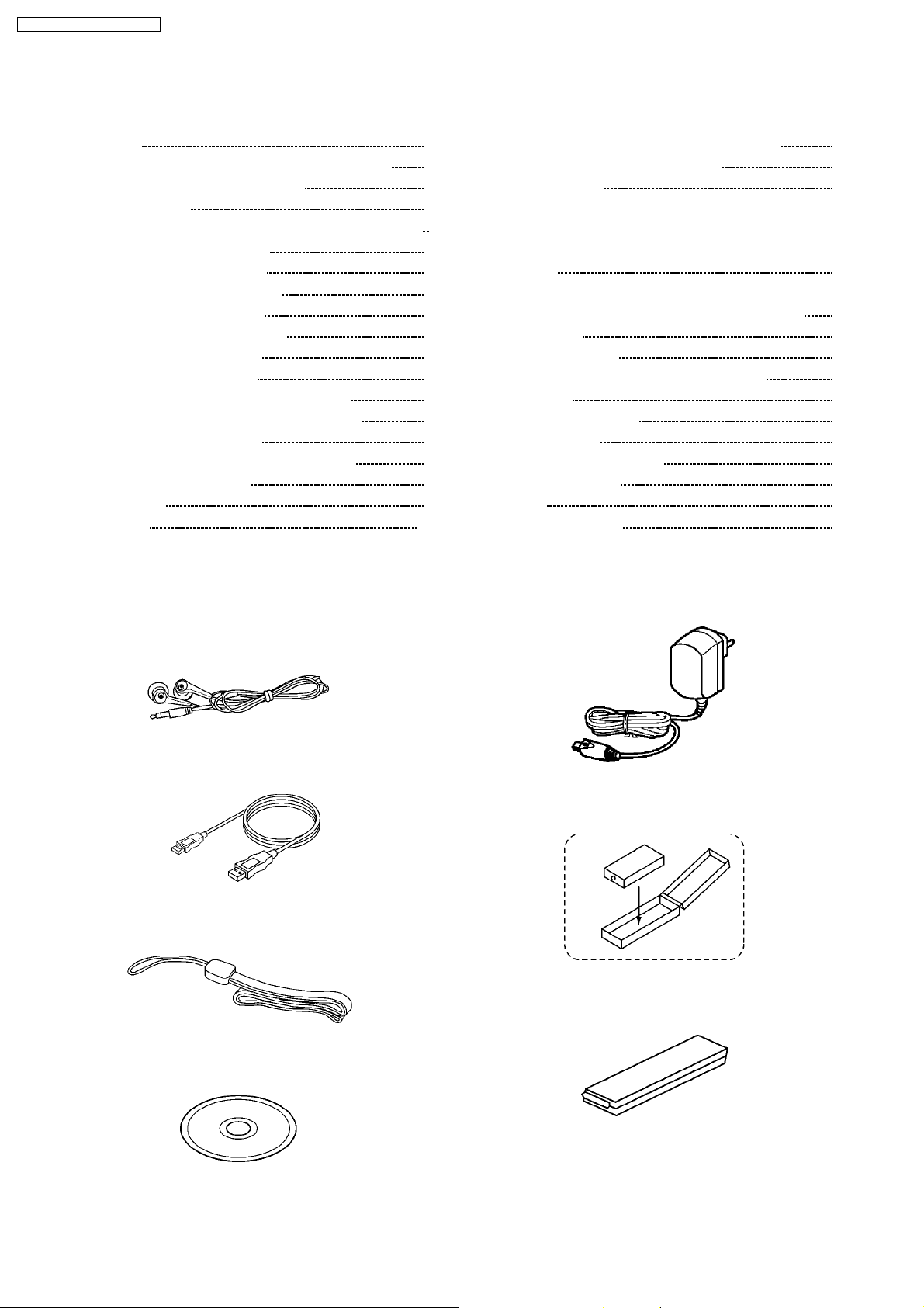
1 Accessories
Stereo earphones
·
(L0BAB0000188) ............................................................. 1pc.
USB Cable
·
(K1HA05AD0003)............. ................................................ 1pc.
Neck Strap
·
(RFAT0006-Q) ....................................................................1pc.
Battery Ass’y
·
(ZBRP-BP65HE)................................................................1pc.
Battery Case
·
(RFCT0005-H) ............................................................ 1pc.
CD-ROM Driver
·
(RFET0004) ...................................................................... 1pc.
AC Adaptor
·
(N0JZCD000003) ...............................................................1pc.
2
2 Supply of Rechargeable
Battery as Replacement
Parts
Please take note of the following points relating to Carrying
·
Case to be used for protection of Rechargeable Battery
from shorting.
Replacement Parts:
Rechargeable Battery (ZBRP-BP65HE) to be supplied will
·
be provided with Carrying Case (RFCT0005-H).
No replacement parts will be supplied for Rechargeable
·
Battery without Case.
Replacement parts will be supplie d for Carrying Case
·
(RFCT0005-H) without Rechargeable Battery.
To your customers, delivery Rechargeable Battery together
·
with Carrying Case to prevent shorting accidents that may
occur when Rechargeable Battery is carried about without
Carrying Case.
SV-MP720VSG / SV-MP73 0VSG
3 Caution in Use of
Rechargeable Battery
Take Rechargeable Battery out of Carrying Case and use
·
iy. Be sure to carry Rechargeable Battery in this Carrying
Case. If not, may either head or ignite by shorting with a
metal.
3
SV-MP720VSG / SV-MP73 0VSG
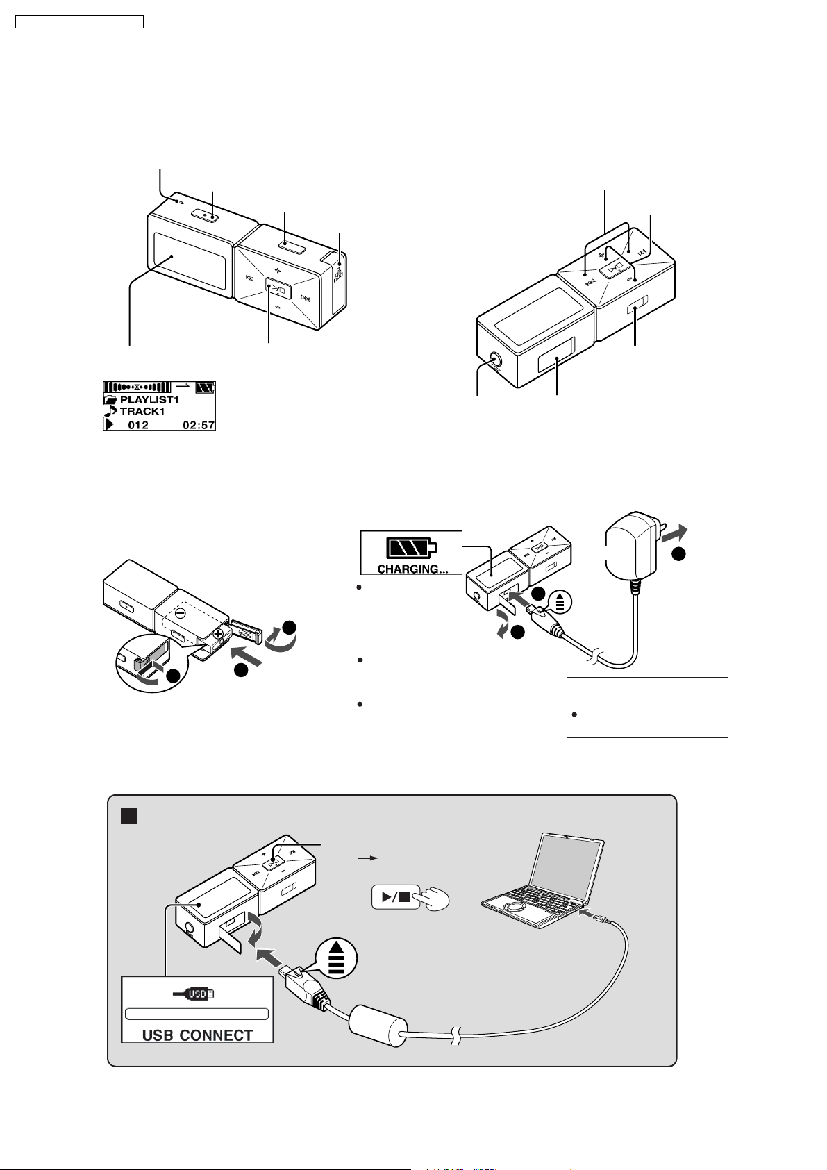
4 Location of Controls
Location of Controls
Microphone
REC/STOP
DMODE
Skip/search
Volume
Battery lid
Display
Example:MUSIC
Rechargeable battery (included)
Insert the
1
rechargeable battery.
1
Turn on, off (Press and hold)/
Play/Stop
2
"CHARGING"
3
2
Earphones jack
(3.5 mm stereo)
Charge before initial use
Charge the battery.
appears on the
display after
connecting the
adaptor.
Recharging also takes place when
the player is connected to a
computer's USB port.
Operation cannot be guaranteed if you
use a USB hub or extension cable.
AC
1
USB port
AC Adaptor
Insert so
2
the arrow
is facing
upwards
Recharging time:
The display will turn off when
recharging is complete.
HOLD
switch
3
To a
household
mains
socket
Approx. 6 hours
Connecting to a computer and downloading files
Connection
Press and hold
Turn the unit on.
1
into mode select
frame.
4
To USB
port
2
Insert so the
3
arrow is facing
upwards.
4
Small end to
player, large
end to PC
SV-MP720VSG / SV-MP73 0VSG
5 Operation Checks and
Component Replacement
Procedures
1. This section describes procedures for checking the
operation of the major printed circuit boards and replacing
the main components.
2. For reassembly after operation checks or replacement,
reverse the respective procedures special ressembly
procedures are described only when required.
3. Select item from the following index when checks or
replacement are required.
Contents
1. Checking for the main P.C.B.
2. Checking for the memory P.C.B.
3. Checking for the tuner P.C.B.
4. Checking for the LCD ass’y.
5. Checking for the prevent electrostatic discharge.
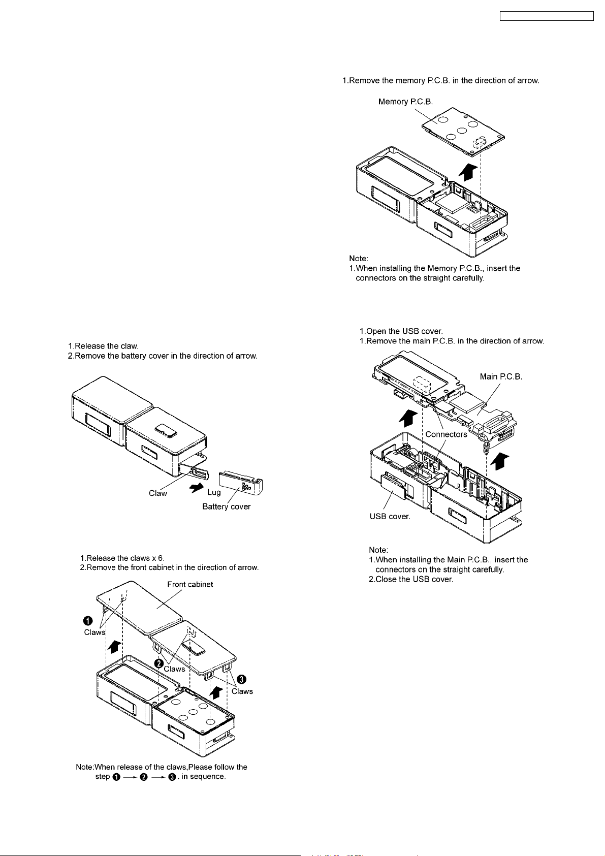
5.1. Removal of the battery cover
5.3. Removal of the memory P.C.B.
5.4. Removal of the main P.C.B.
5.2. Removal of the front cabinet
5
SV-MP720VSG / SV-MP73 0VSG
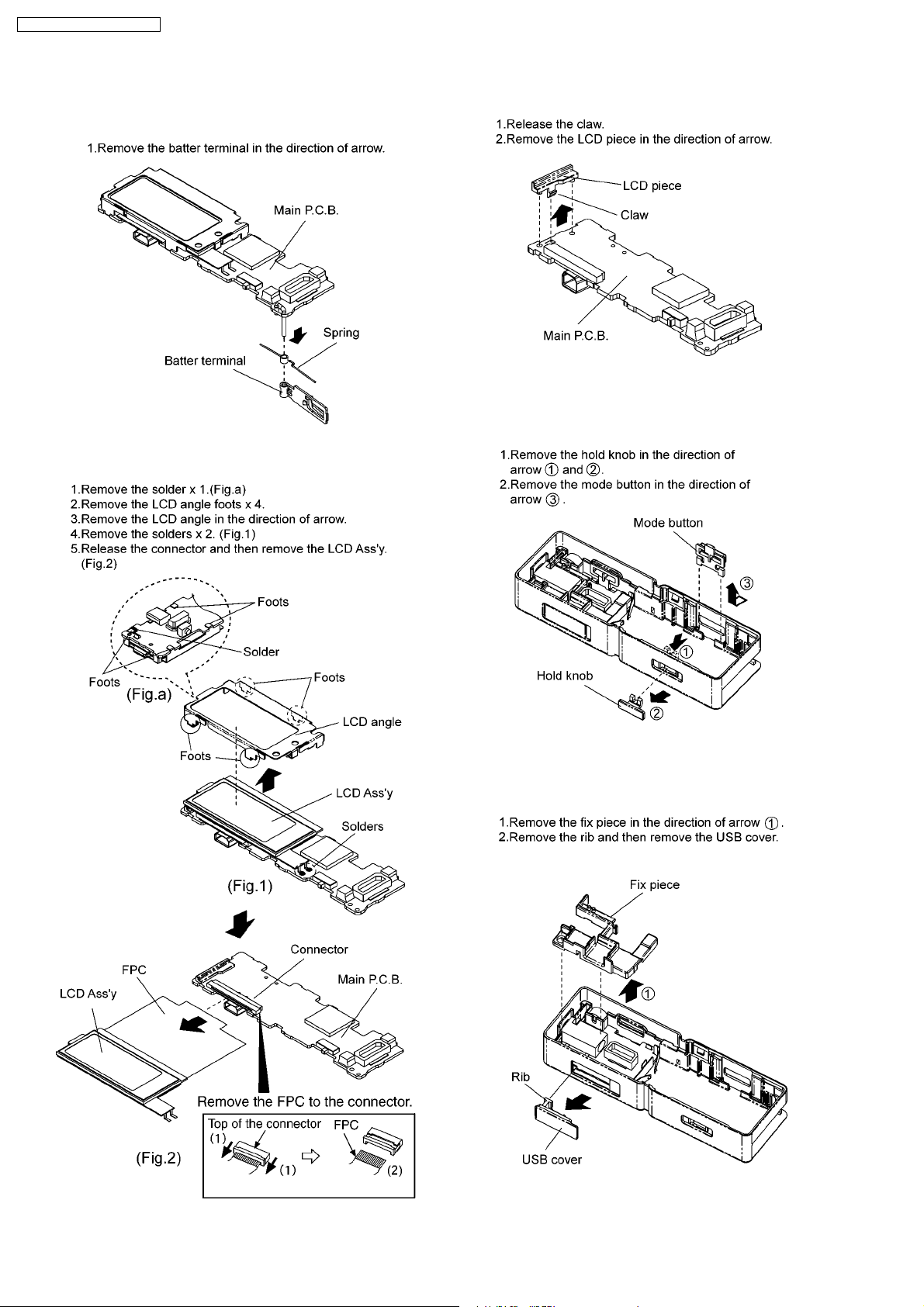
5.5. Removal of the battery
terminal.
5.6. Removal of the LCD Ass’y
5.7. Removal of the LCD Piece
5.8. Removal of the mode button
and hold knob
5.9. Removal of the USB fix piece
and USB cover
6
SV-MP720VSG / SV-MP73 0VSG
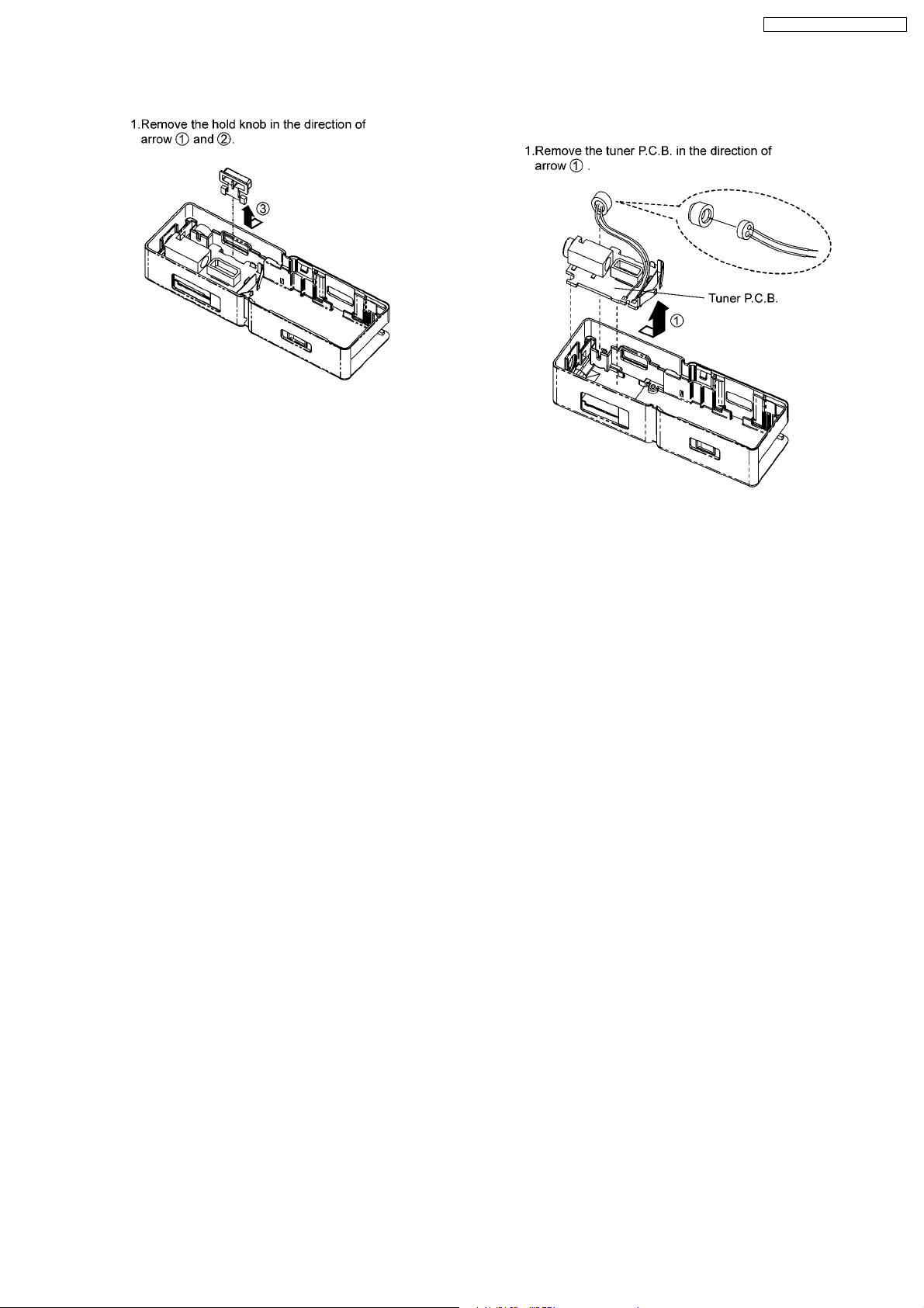
5.10. Removal of the REC button 5.11. Removal of the tuner P.C.B.
and MIC ass’y
7
SV-MP720VSG / SV-MP73 0VSG
6 Instructions for Repair Service
8
7 Service Position
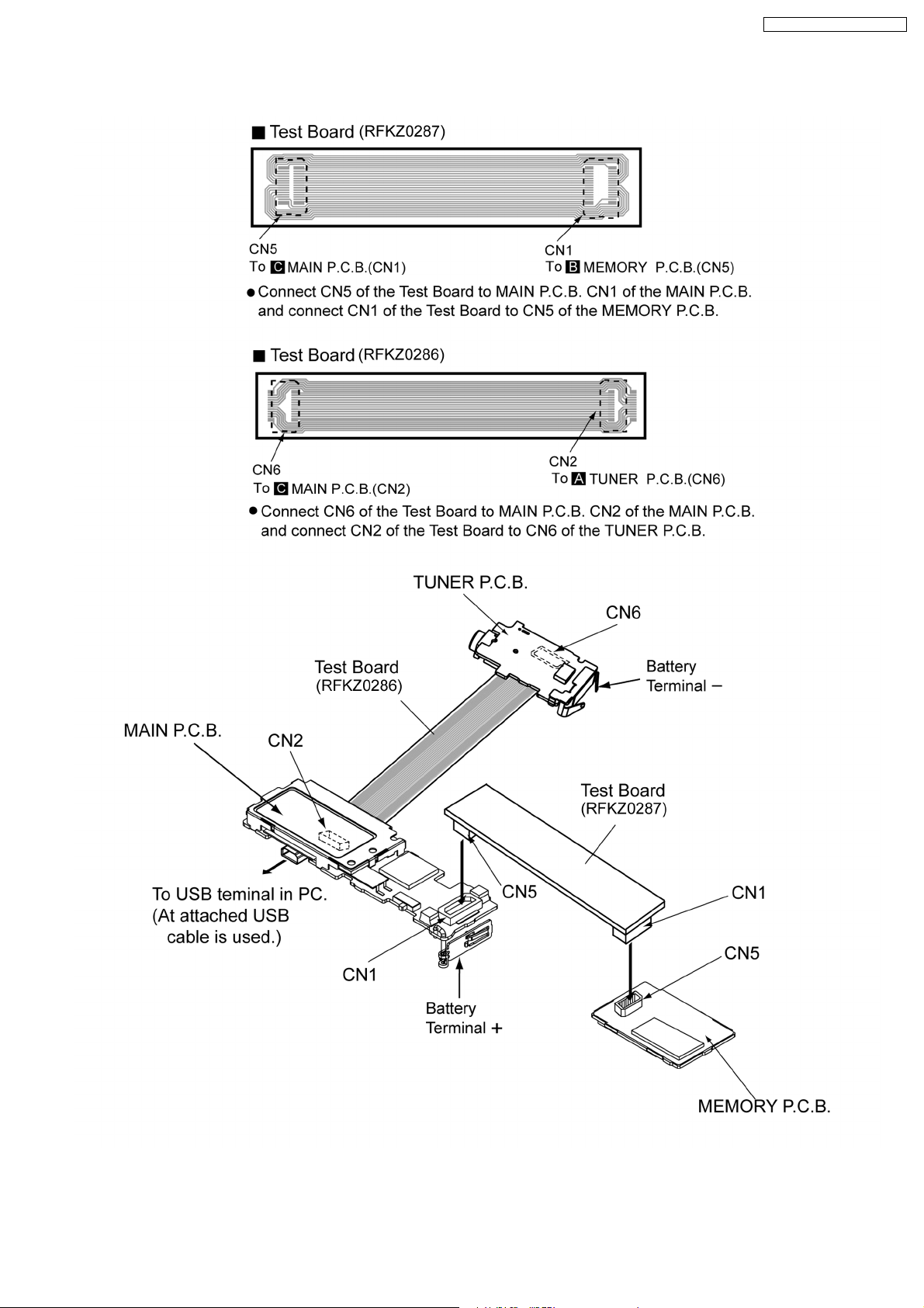
SV-MP720VSG / SV-MP73 0VSG
9
SV-MP720VSG / SV-MP73 0VSG
8 Service Mode
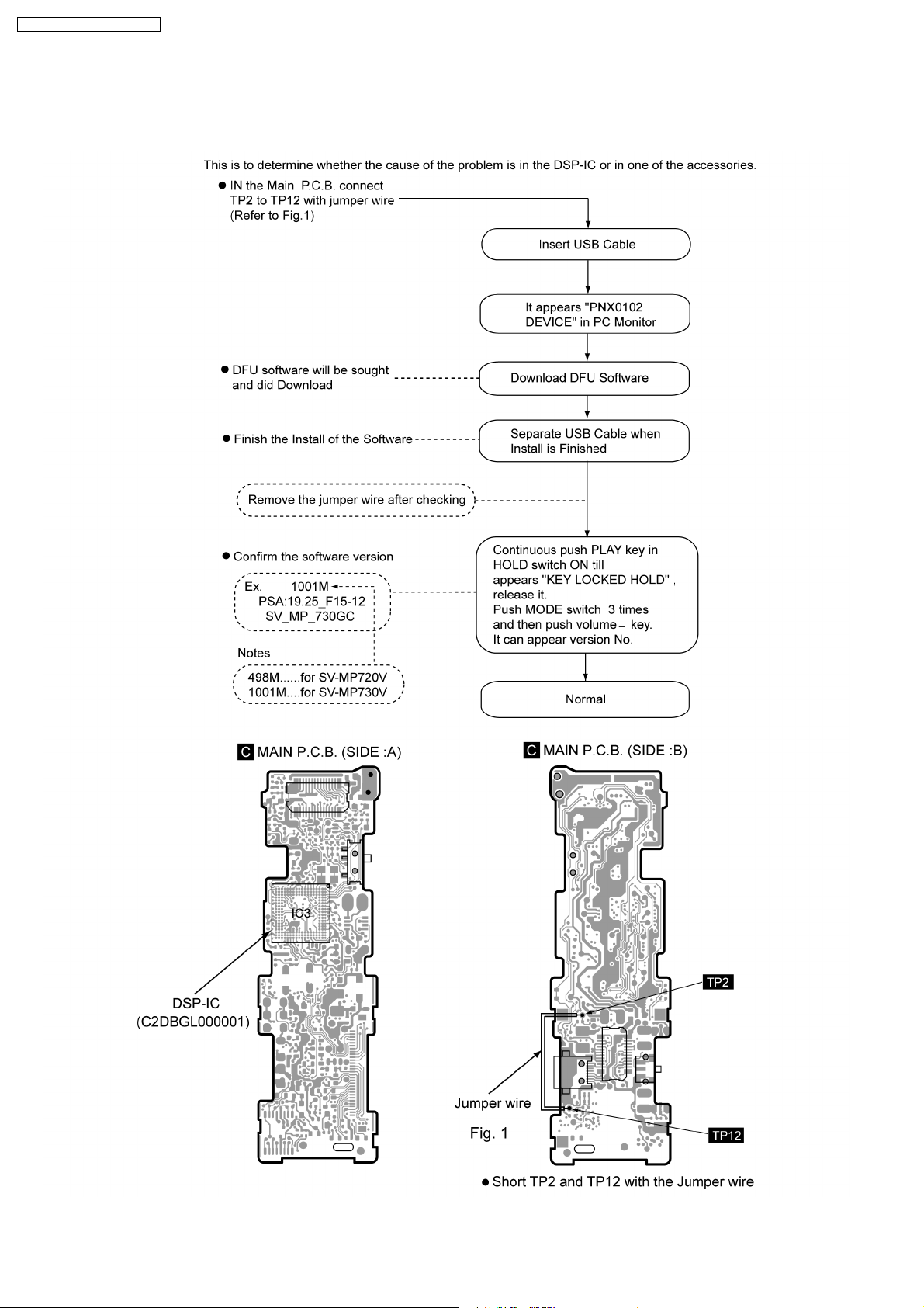
8.1. Checking Procedures for IC3 C2HBZG000008
10
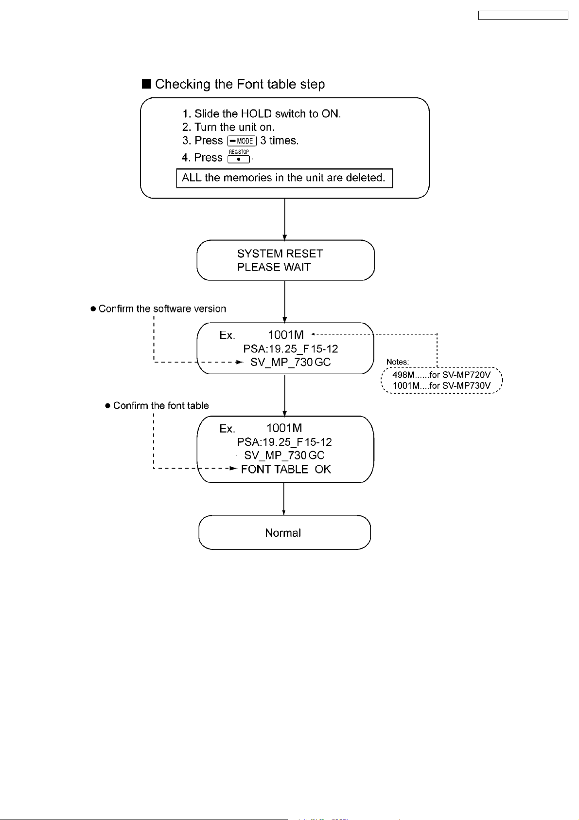
8.2. Checking Procedures for Font table
SV-MP720VSG / SV-MP73 0VSG
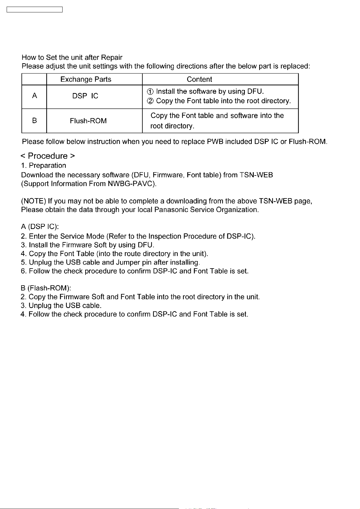
9 Service Precautions
9.1. Install and Copy the software (DFU,firmware,font table) After replacing
the main PCB and DSP IC (main CPU),reinstall DFU and firmware,and
copy font table again.
9.2. Please contact to the service organization of the belonging for the
acquisition of data and obtain the software.
11
 Loading...