

Panasonic SVMP-35-MP Service manual
Digital Audio Player
SV-MP35VP
Colour
(S)................... Silver Type
TD0403016C1
A1
Specifications
Memory size: 256 MB
Supported sampling frequency: MP3; 32 kHz, 44.1 kHz, 48 kHz,
WMA; 8 kHz to 44.1 kHz
Supported bit-rates: MP3; 8 kbps to 320 kbps (128
kbps is recommend) WMA; 32
kbps to 192 kbps (96 kbps is
recommend)
No. of channels: Stereo, 2 channels (PLATER,FM
RADIO) Mono, 1 channel (IC
RECORDER)
Frequency response: 20Hz to 20,000Hz (+0dB, -6dB)
(PLAYER) 300 Hz to 4,300 Hz (IC
RECORDER,HQ mode)
Mic S/N: 37 dB (IC RECORDER,HQ mode)
Radio Frequency range (FM): 87.9 MHz to 107.9 MHz (200 kHz
steps),87.5 MHz to 108.0 MHz
(100 kHz / 50 kHz steps)
Output: 4.5mW + 4.5mW (32Ω,M3 jack)
Power supply: DC 1.5V (one LR03,AAA,AM-4
battery)
Approximate play times: 10 hours (alkaline
battery,PLAYER) 6 hours (alkaline
battery,FM RADIO)
Approximate recording times: 15 hours (alkaline battery, IC
RECORDER, LP mode) 5 hours
30 minutes (alkaline battery,FM
RADIO)
Maximum dimensions (WxHxD): 43.8 x 61.5 x 21.9mm
Cabinet dimensions (WxHxD): 42.1 x 60.0 x 21.9mm
Mass: 45.5g with battery
· Specifications are subject to change without notice.
· The play times shown depend on operating conditions.
· Mass and dimensions are approximate.
· MB means one million bytes. Useable capacity may be less.
3
(1
/4”x27/16”x7/8”)
11
(1
/16”x23/8”x7/8”)
(1.605 oz)
34.1g without battery
(1.200 oz)
© 2004 Matsushita Electric TAIWAN Industrial Co.,
Ltd. All rights reserved. Unauthorized copying and
distribution is a violation of law.
SV-MP35VP
CONTENTS
Page Page
1 Accessories 2
2 Location of Controls
3 Service Precautions
4 Checking Procedures fo CSP-IC (IC4)
5 REPLACEMENT PROCEDURES FOR CSP (CHIP SIZE
PACKAGE) IC
5.1. EQUIPMENT
6 Troubleshooting
7 Troubleshooting guide
8 The Procedure for Replacement of the CSP IC
(C1BB00000854)
9 Disassembly Instructions
9.1. Removal of the front cabinet and main P.C.B.
9.2. Removal of the battery holder and hold knob
9.3. Removal of the SUB P.C.B. and rear cabinet
13
13
14
15
15
15
15
3
4
5
9
9
9.4. Removal of the LCD Ass 馳 16
9.5. Removal of the REC button and function button
9.6. Removal of the sub cover
9.7. Removal of the play knob
9.8. Removal of the battery cover
9.9. Removal of the MIC
9.10. Checking FM Steps
10 Block Diagram
11 Type Illustration of ICs, Transistors and Diodes
12 Schematic Diagram Notes
13 Schematic Diagram
14 Printed Circuit Board Diagram
15 Cabinet Parts Location
16 Packaging
17 Replacement Parts List
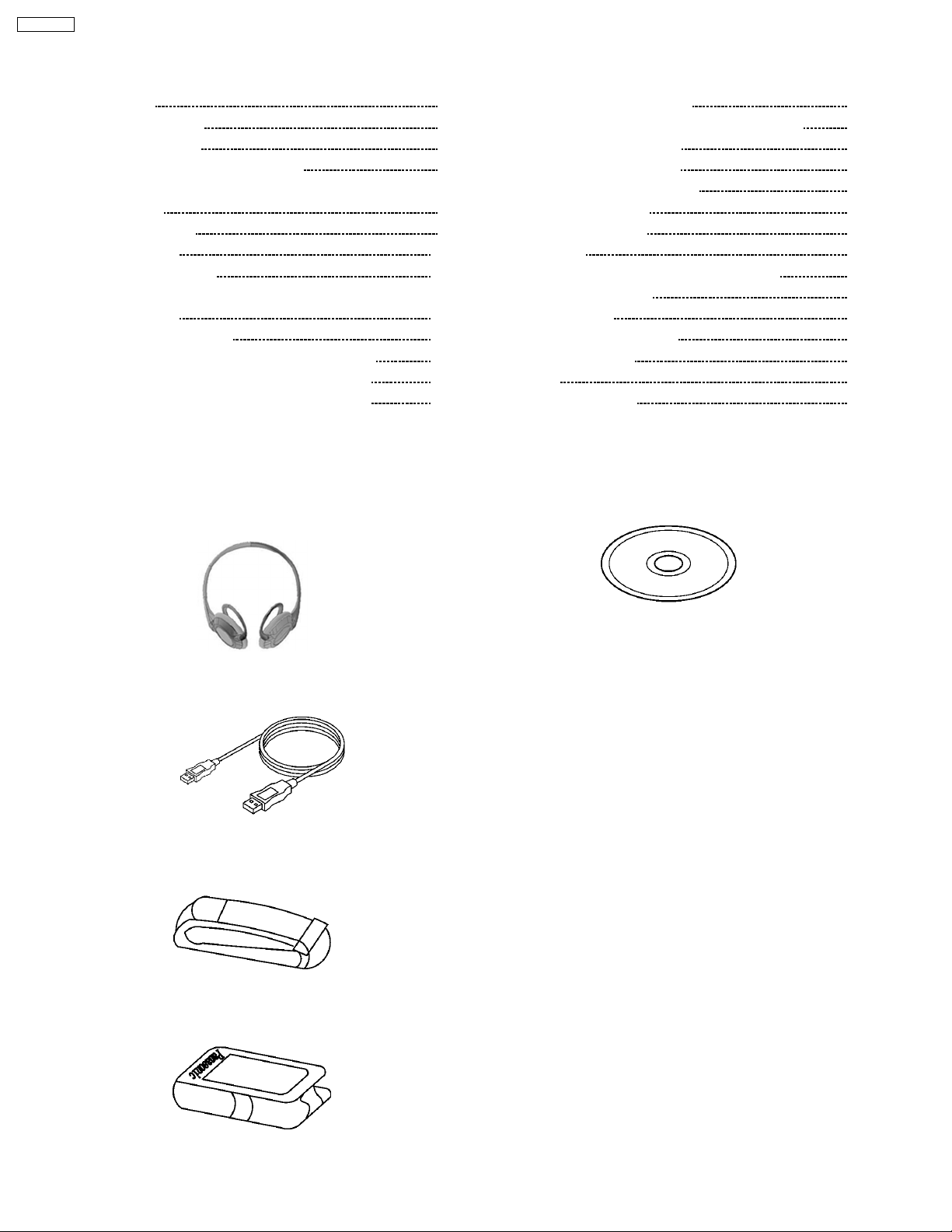
1 Accessories
16
16
16
16
17
17
17
18
18
19
23
27
28
29
· Stereo Headphones
(L0BAD0000170) ............................................................. 1pc.
· USB Cable
(K1HA05AD0001)............. ................................................ 1pc.
· Arm Band
(RKHT0002A-K) ................................................................ 1pc.
(RFE0164) ........................................................................ 1pc.
· Leather Bag
(RFCT0021-K) ..................................................................1pc.
· CD-ROM Driver
2
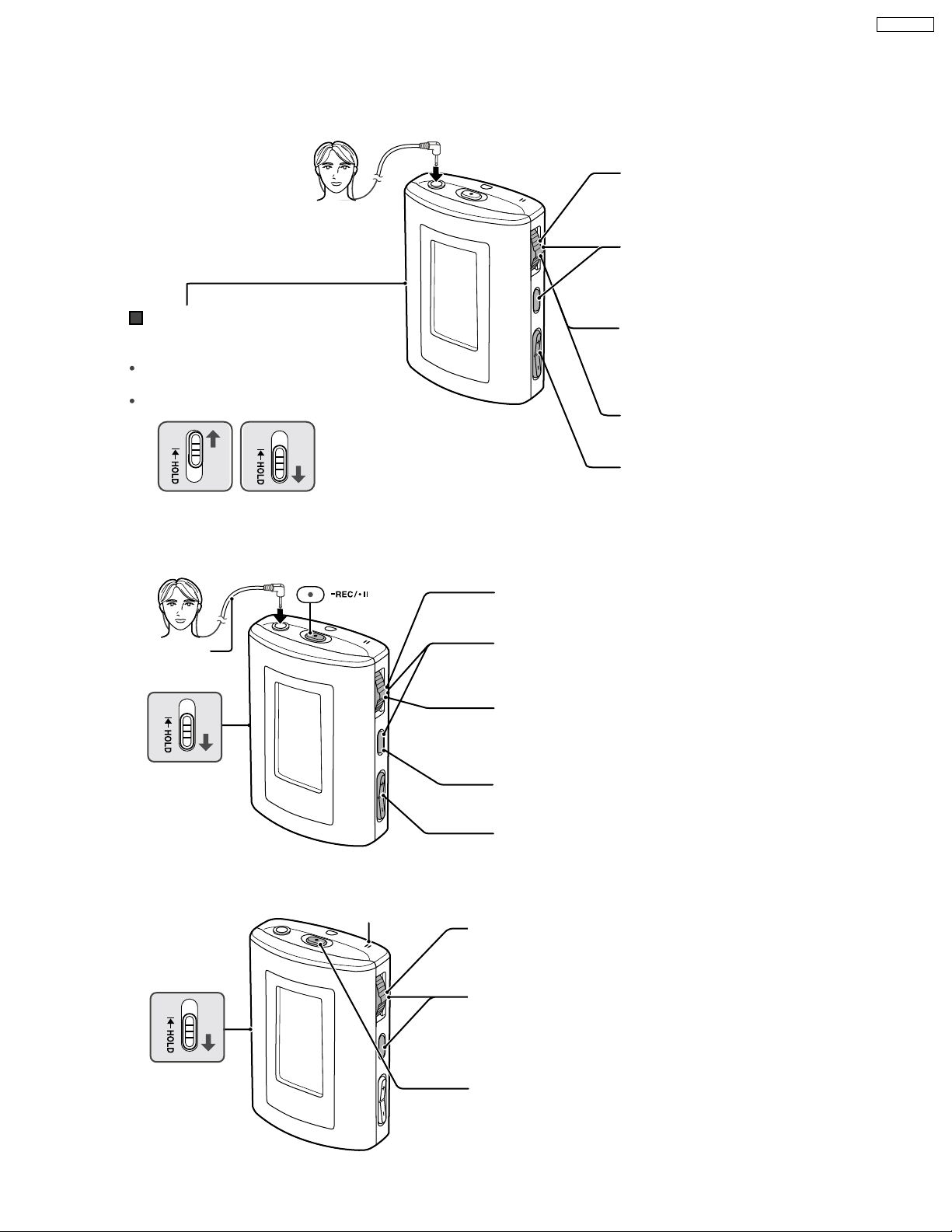
2 Location of Controls
Playing tracks (PLAYER mode)
SV-MP35VP
LR
HOLD mode
Switch on so the unit doesnÕt respond
when you press buttons to prevent:
The unit turning on unexpectedly and
wasting the battery.
Interruptions to play or recording.
HOLD mode Release (before operation)
Using the FM radio (FM RADIO mode)
LR
Turn the unit on.
1
Turn the unit on.
1
Select PLAYER
2
Skip this step if PLAYER is
already selected.
Select the play list.
3
To play recordings, select the
IC RECORDER or TUNER
(FM RADIO) play lists.
Start play.
4
Adjust the volume.
5
Play stops at the end of the list.
Extend the
headphone cord.
2
3
Release
4
5
Voice recording (IC RECORDER mode)
Microphone
Turn the unit on.
1
Select IC RECORDER.
2
Skip this step if IC
RECORDER is already
selected.
Release
Start recording.
3
Select FM RADIO.
Skip this step if FM
RADIO is already selected.
Select the station.
In the manual mode, push and hold until the frequency
starts scrolling to start automatic tuning. Tuning stops
when a station is found.
Select manual
or preset mode.
Ajust the volume.
Speak into the microphone.
4
3

SV-MP35VP
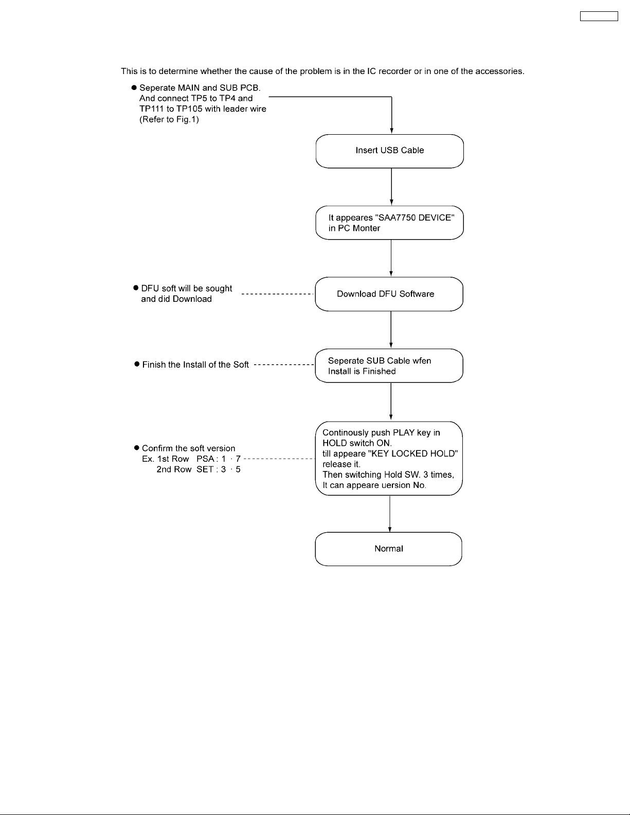
3 Service Precautions
Caution-1
Reinstall and Copy the software(DFU, Firmware, Font table) after replacing the main P.C.B. and DSP IC(main CPU), reinstall
DFU and Firmware, and copy font table again.
Please refer to “The Method of install DFU Software” for the method of install.
Caution-2
Please obtain the data through your local Panasonic service organization.
4
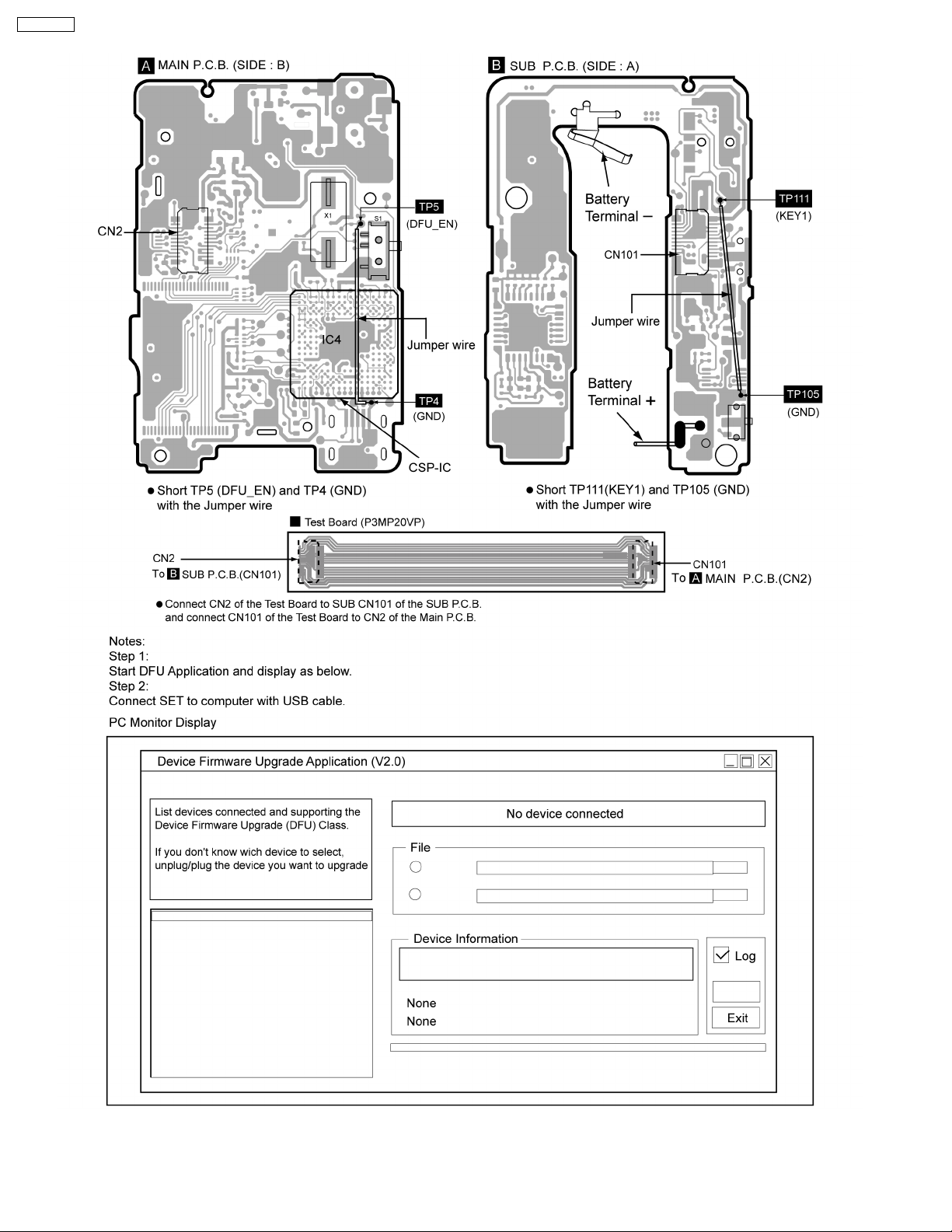
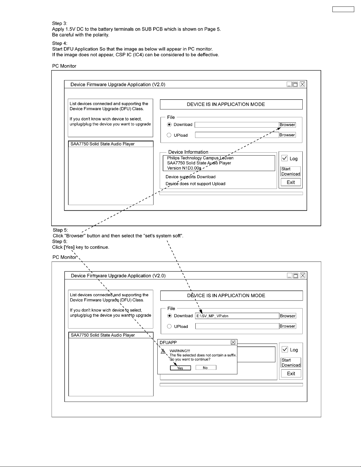
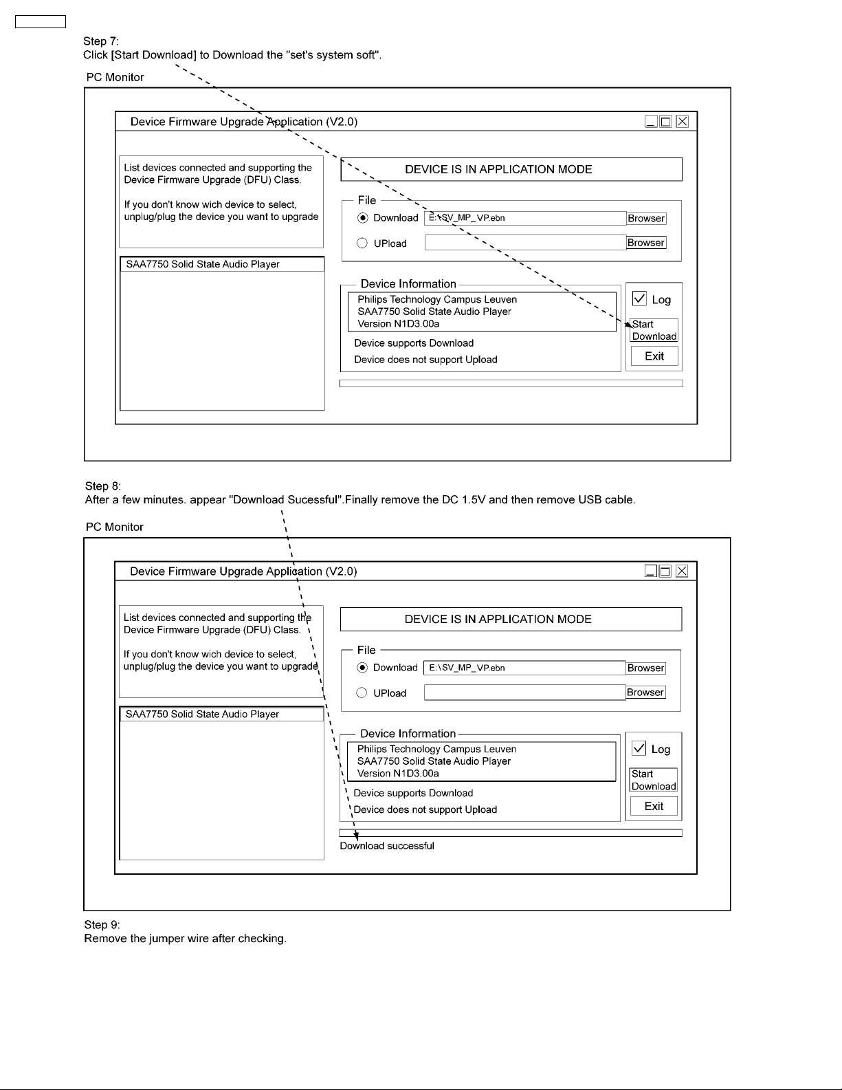
4 Checking Procedures fo CSP-IC (IC4)
SV-MP35VP
5
SV-MP35VP
6
SV-MP35VP
7
SV-MP35VP
8
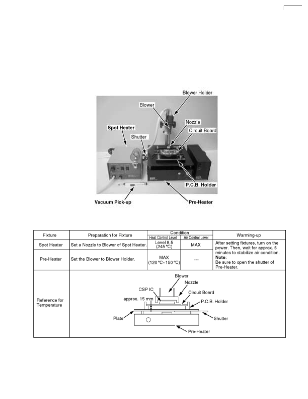
5 REPLACEMENT PROCEDURES FOR CSP (CHIP SIZE
PACKAGE) IC
5.1. EQUIPMENT
1.Pre-Heater
2.Spot Heater
3.Vacuum Pick-up
4.P.C.B. Holder
SV-MP35VP
Fig. 9-1
Fig. 9-2
9
 Loading...