

Page 1

SAFETY BEAM SENSOR
ST4
Instruction Manual
Page 2

BEFORE BEGINNING
The printed English and Japanese versions of this instruction manual are the original versions.
The English, French, German, Italian and Spanish versions published in the Internet are
copies of the original documentation and were produced by Panasonic Electric Works Europe
AG.
Liability and Copyright for the Hardware
This manual and everything described in it are copyrighted. You may not copy this manual, in
whole or part, without written consent of Panasonic Electric Works Europe AG (PEWEU).
PEWEU pursues a policy of continuous improvement of the design and performance of its
products. Therefore we reserve the right to change the manual/product without notice. In no
event will PEWEU be liable for direct, special, incidental, or consequential damage resulting
from any defect in the product or its documentation, even if advised of the possibility of such
damages.
We invite your comments on this manual. Please e-mail us at:
tech-doc@eu.pewg.panasonic.com.
Please direct support matters and technical questions to your local Panasonic representative.
LIMITED WARRANTY
If physical defects caused by distribution are found, PEWEU will replace/repair the product
free of charge. Exceptions include:
• When physical defects are due to different usage/treatment of the product other than
described in the manual.
• When physical defects are due to defective equipment other than the distributed
product.
• When physical defects are due to modifications/repairs by someone other than
PEWEU.
• When physical defects are due to natural disasters.
Page 3
Important Symbols
One or more of the following symbols may be used in this documentation:
DANGER!
1.
2.
3.
!
CAUTION
Indicates that you should proceed with caution. Failure to do so may result in
injury or significant damage to instruments or their contents, e.g. data.
NOTE
Contains important additional information.
EXAMPLE
Contains an illustrative example of the previous text section.
Procedure
The warning triangle indicates especially important safety
instructions. If they are not adhered to, the results could be fatal
or critical injury.
Indicates that a step-by-step procedure follows.
REFERENCE
Indicates where you can find additional information on the subject at hand.
Page 4
KEY POINTS
Summarizes key points in a concise manner.
SHORTCUTS
Provides helpful keyboard shortcuts.
EXPLANATION
Provides a brief explanation of a function, e.g. why or when you should use it.
next page
Indicates that the text will be continued on the next page.
Page 5

Panasonic ST4 Instruction Manual
Table of Contents
Table of Contents
1. Introduction ............................................................................1
1.1 Target Group ............................................................................................. 2
1.2 Safety Instructions..................................................................................... 3
1.3 Applicable Standards/Regulations............................................................. 6
2. Before Using this Device .......................................................7
2.1 Features..................................................................................................... 8
2.2 Part Description......................................................................................... 9
2.2.1 Elements of the Controller ST4-C11 ........................................................10
2.2.2 Elements of the Multifunctional Controller ST4-C12EX ...........................11
2.2.3 Elements of the Sensor ST4-A.................................................................14
2.3 Protection Area........................................................................................ 15
2.3.1 Sensing Range......................................................................................... 15
2.3.2 Safety Distance ........................................................................................ 16
2.3.2.1 Calculation Example for Europe .....................................................17
2.3.2.2 Calculation Example for the US ...................................................... 18
2.3.3 Influence of Reflective Surfaces............................................................... 20
2.3.4 Placement of Emitter and Receiver .........................................................21
2.3.5 Connecting Multiple Sensors Heads........................................................ 23
2.3.6 Address Allocations of the Sensor ST4-A.............................................. 25
2.4 Mounting and Removing.......................................................................... 29
2.4.1 Mounting and Removing the Controller ...................................................29
2.4.2 Mounting the Sensor ST4-A...................................................................30
2.4.3 Connecting Controller and Sensor ST4-A .............................................31
2.4.4 Series Connection of the Sensor ST4-A................................................32
v
Page 6

Table of Contents
Panasonic ST4 Instruction Manual
2.5 Wiring .......................................................................................................36
2.5.1 Power Supply Unit....................................................................................36
2.5.2 I/O Circuit Diagrams ................................................................................. 37
2.5.2.1 Circuit of Controller ST4-C11 .......................................................... 37
2.5.2.2 Circuit of Multifunctional Controller ST4-C12EX ............................. 38
2.5.2.3 Manual and automatic reset............................................................39
2.5.2.4 Emission Halt Input Terminals ........................................................40
2.5.3 Connecting to the Terminal Block ............................................................41
2.5.4 Terminal Arrangement Diagram...............................................................41
2.6 Adjustment and Operation........................................................................44
2.6.1 Beam-Axis Alignment...............................................................................44
2.6.2 Operation Test..........................................................................................46
2.6.3 Operation..................................................................................................47
3. Functions.............................................................................. 49
3.1 Self-Diagnosis Function ...........................................................................50
3.2 Reset Operation .......................................................................................51
3.2.1 Manual Reset ...........................................................................................51
3.2.2 Auto Reset................................................................................................52
3.3 Emission Halt Function.............................................................................53
3.4 Interference Prevention Function .............................................................54
3.4.1 Interference Prevention With One Controller ...........................................54
3.4.2 Interference Prevention Function When Using Two or More Controllers 54
3.5 Auxiliary Output ........................................................................................56
3.5.1 Auxiliary Output Operation of Controller ST4-C11...................................56
3.5.2 Auxiliary Output Operation of Controller ST4-C12EX .............................. 56
3.5.3 Emission Amount Adjustment Function ...................................................57
3.6 Muting Function (Only for ST4-C12EX)....................................................59
vi
3.6.1 What Is a Muting Sensor..........................................................................60
3.6.2 Installation of the Muting Sensor..............................................................60
Page 7

Panasonic ST4 Instruction Manual
Table of Contents
3.7 Override Function (Only ST4-C12EX) .....................................................63
3.8 Muting Pattern Selection Function (Only ST4-C12EX)............................ 67
3.8.1 Control Condition of Muting Pattern No. 1 ............................................... 68
3.8.2 Control Condition of Muting Pattern No. 2 ............................................... 69
3.8.3 Control Condition of Muting Pattern No. 3 ............................................... 70
3.9 Sensor Diagnosis Function (Only ST4-C12EX)....................................... 71
3.10 Muting Lamp Diagnosis Function (Only ST4-C12EX) ............................. 74
4. Maintenance..........................................................................75
4.1 Daily Inspection ....................................................................................... 76
4.2 Periodic Inspection Checklist (Every Six Months) ................................... 77
4.3 Inspection After Maintenance .................................................................. 78
5. Troubleshooting ...................................................................79
5.1 Troubleshooting of Controller ST4-C11 ................................................... 80
5.2 Troubleshooting of Controller ST4-C12EX .............................................. 83
5.3 Troubleshooting of the Sensor ST4-A ................................................... 86
6. Specifications .......................................................................87
6.1 Specifications, Controller ST4-C11.......................................................... 88
6.2 Specifications, Controller ST4-C12EX..................................................... 90
6.3 Specifications, Sensor ST4-A ................................................................ 92
6.4 Options .................................................................................................... 93
6.4.1 Extension Cable .......................................................................................93
6.4.2 Branch Cable............................................................................................93
6.4.3 Foot Angled Mounting Bracket................................................................. 93
vii
Page 8

Table of Contents
6.4.4 Back Angled Mounting Bracket ................................................................ 94
6.4.5 Foot Biangled Protective Mounting Bracket.............................................94
6.4.6 Slit Masks .................................................................................................94
Panasonic ST4 Instruction Manual
7. Dimensions........................................................................... 95
7.1 Controller ST4-C11 ..................................................................................96
7.2 Multifunctional Controller ST4-C12EX......................................................97
7.3 Single-beam Sensor ST4-A ...................................................................98
7.4 Branch Cable ST4-CCJ05-WY.................................................................99
7.5 Foot Angled Mounting Bracket MS-CX-1 ...............................................100
7.6 Back Angled Mounting Bracket MS-ST4-3.............................................101
7.7 Foot Biangled Protective Mounting Bracket MS-ST4-6..........................102
8. Glossary of Terms.............................................................. 103
9. Index.................................................................................... 105
viii
Page 9

Chapter 1
Introduction
Page 10

Introduction
Panasonic ST4 Instruction Manual
1.1 Target Group
Thank you for purchasing the PanasonicSafety Beam Sensor ST4 series (hereafter called 'this
device'). Please read this instruction manual carefully and thoroughly for the correct and
optimum use of this product. Kindly keep this manual in a convenient place for quick reference.
This device is a safety beam sensor for protecting a person from dangerous parts of a machine
which can cause injury or accident.
This manual has been written for the personnel who:
• have undergone suitable training and have knowledge of safety beam sensors as well
as safety systems and standards.
• are responsible for this device
• design systems using this device
• install and connect this device
• manage and operate a plant using this device
Machine designer, installer, employer and operator
The machine designer, installer, employer and operator are solely responsible for ensuring that
all applicable legal requirements relating to the installation and the use in any application are
satisfied and all instructions for installation and maintenance contained in the instruction manual
are followed.
Whether this device functions as intended and systems including this device comply with safety
regulations depend on the appropriateness of the application, installation, maintenance and
operation. The machine designer, installer, employer and operator are solely responsible for
these items.
Engineer
The engineer must be a person who is appropriately trained, has widespread knowledge and
experience, and can solve various problems which may arise in his field of work, e.g. as a
machine designer or a person in charge of installation or operation, etc.
Operator
The operator should read this instruction manual thoroughly, understand its contents, and
perform operations following the procedures described in this manual for the correct operation
of this device.
In case this device does not perform properly, the operator should report this to the person in
charge and stop machine operation immediately. The machine must not be used until correct
performance of this device has been confirmed.
2
Page 11

Panasonic ST4 Instruction Manual
1.2 Safety Instructions
DANGER!
1.2 Safety Instructions
!
• Use this device as per its specifications. Do not modify the safety beam
sensor since its functions and capabilities may not be maintained and it may
malfunction.
• The safety beam sensor has been developed/produced for industrial use
only.
• Do not use the safety beam sensor under conditions or in environments not
described in this manual. Please consult us if there is no other choice but to
use this device in such an environment.
• Do not use the safety beam sensor in fields such as nuclear power control,
railroad, aircraft, automobiles, combustion facilities, medical systems,
aerospace development, e.g. in applications where failure could result in
large-scale damage to society or people.
• When the safety beam sensor is to be used for enforcing protection of a
person from any danger occurring around an operating machine, the user
must satisfy the regulations established by national or regional security
committees.
• No matter what kind of equipment you use the device with, follow the safety
regulations in regard to appropriate usage, mounting (installation), operation
and maintenance.
Please adhere to the following safety instructions when
you install and operate this device. Failure to do so can
result in fatal or critical injury during unprotected use of
hazardous machinery.
• Use the safety beam sensor by installing suitable protective equipment as a
countermeasure for failure, damage, or malfunction of this device.
• Before using this sensor, check whether the device performs properly and
has the functions and capabilities as stated in the design specifications.
• Dispose of the safety beam sensor as industrial waste.
Environment
• Do not use a mobile phone or a radio phone near this device.
• If the sensor is installed in a place where there are reflective surfaces, make
sure to install this device so that reflected light from the reflective surfaces
does not affect the receiver. Alternatively, take countermeasures such as
painting, masking, roughening, or changing the material of the reflective
surfaces, etc. Failure to do so may cause the sensor not to detect properly,
which may result in death or serious injury.
• Do not install the safety beam sensor in the following environments:
3
Page 12

Introduction
Installation
• Always keep the correctly calculated safety distance between the safety
• Install an extra protective structure around the machine so that the operator
• Install the beam sensor in a manner that some part of the operator's body
Panasonic ST4 Instruction Manual
- Areas exposed to intense interference light such as direct sunlight
- Areas with high humidity where condensation is likely to occur
- Areas exposed to corrosive or explosive gases
- Areas exposed to vibration or shock at levels higher than those specified
- Areas exposed to contact with water
- Areas exposed to excessive steam or dust
- Areas where the beam-receiving part of this device is directly exposed to
light from a high-frequency fluorescent lamp (inverter type) or
rapid-starter fluorescent lamp.
beam sensor and the dangerous parts of the machine.
must pass through the sensing area of the safety beam sensor to reach the
dangerous parts of the machine.
always remains in the sensing area until the operator has finished working
with the dangerous parts of the machine.
• Do not install the beam sensor at a location where it can be affected by wall
reflection.
• When installing multiple sets of the safety beam sensor, connect the sets
and, if necessary, install some barriers so that mutual interference does not
occur.
• Do not use any reflection type or recursive reflection type arrangement.
Equipment in which this device is installed
• When the safety beam sensor is used in the PSDI mode, an appropriate
control circuit must be configured between this device and the machinery.
For details, be sure to refer to the standards or regulations applicable in each
region or country.
• In Japan, do not use the safety beam sensor as safety equipment for a press
machine.
• Do not install the safety beam sensor with a machine whose operation
cannot be stopped immediately in the middle of an operation cycle by an
emergency stop.
• This sensor provides safety 2 seconds after the power has been switched
ON. Make sure that the control system takes the time delay into
consideration.
Wiring
• Switch off the power before wiring the safety beam sensor.
4
Page 13

Panasonic ST4 Instruction Manual
• All electrical wiring should conform to the regional electrical regulations and
laws. The wiring should be done by skilled personnel with the required
electrical knowledge.
• Do not run the sensor cable together with high-voltage lines or power lines
or put them together in the same raceway.
• In case you need to extend the cable of the ST4-A□, you can use the
dedicated extension cable. The cable can be extended up to 50m (emitter and
receiver, respectively).
• Do not control the device at only one control output (OSSD 1, OSSD 2).
• To ensure that the output is not turned ON due to an earth fault of the control
output (OSSD 1, OSSD 2), ground the device on the 0V side (for PNP output)
or +24V side (for NPN output).
Maintenance
• When you need to replace parts, always use only genuine replacement parts
from the supplier. If you use substitute parts from another manufacturer, the
sensor may fail to detect properly, which may result in death or serious body
injury.
• The device must be inspected periodically by an engineer with the required
knowledge.
1.2 Safety Instructions
Others
• When you have adjusted or maintained the device, test the device following
the procedure specified in the maintenance chapter before you switch the
system back on.
• Clean this device with a clean cloth. Do not use thinner-based cleaners.
• Never modify this device. If you modify the device, the sensor may fail to
detect properly, which may result in death or serious injury.
• Do not use this device to detect objects flying over the sensing area.
• Do not use this device to detect transparent objects, translucent objects or
objects smaller than the specified minimum sensing size.
5
Page 14
Introduction
Panasonic ST4 Instruction Manual
1.3 Applicable Standards/Regulations
This device complies with the following standards and regulations.
• EU Machinery Directive 98/37/EC, EMC Directive 2004/108/EC
• EN 61496-1 (Type 4), EN 55011, EN 50178,
EN ISO 13849 (Category 4, PLe), EN 61508-1 to 7 (SIL3)
• IEC 61496-1/2 (Type 4), ISO 13849-1 (Category 4, PLe),
IEC 61508-1 to 7 (SIL3), IEC 62061 (SIL3)
• JIS B 9704-1/2 (Type 4), JIS B 9705-1 (ISO 13849-1) (Category 4), JIS C 0508-1 to 7
(SIL3)
• UL 61496-1/2 (Type 4), UL 1998, CSA C22.2 No.14, CSA C22.2 No.0.8
• OSHA 1910.212, OSHA 19 10.217(C), ANSI B11.1 to B11.19, ANSI/RIA 15.06,
ANSI/ISA S84.01 (SIL3)
NOTE
• Conformity to JIS, OSHA and ANSI for this device has been evaluated by us.
•
directive. The CE-mark indicates that this product conforms to the EMC
directive.
•
•
Canadian and U.S. requirements.
• If you want to use this device in a location other than already described (see
page
regulations applicable in your region or country.
: This device conforms to the EMC directive and the Machinery
: This device is certified by TÜV Süd.
: The C-CL US Listing Mark indicates compliance with both
3), confirm first that the intended use complies with the standards or
6
Page 15

Chapter 2
Before Using this Device
Page 16

Before Using this Device
Panasonic ST4 Instruction Manual
2.1 Features
This device is a safety beam sensor with the following features.
• The controller ST4-C11 or the multifunctional controller ST4-C12EX is used in
combination with the single-beam sensor ST4-A.
• The type ST4-AV comes with an emission amount adjuster to reduce the emission
amount.
• Up to six units of the ST4-A can be connected per controller. The controller has an
automatic interference prevention function.
• Wiring can be easily done by using the extension cable ST4-CCJ (optional) and the
branch cable ST4-CCJ05-WY (optional), since the cables are connector types
• The control output (OSSD 1/2) is a PNP/NPN output switching type. The output type
can be switched with the output polarity selection switch on the controller.
• Replacing the relay is not necessary since a semiconductor output is used.
• The muting function complying with ISO 12643 (safety requirements for graphic
technology equipment and systems) is available on the ST4-C12EX. For details, refer to
the Muting Function (see page
59).
.
8
Page 17
Panasonic ST4 Instruction Manual
2.2 Part Description
2.2 Part Description
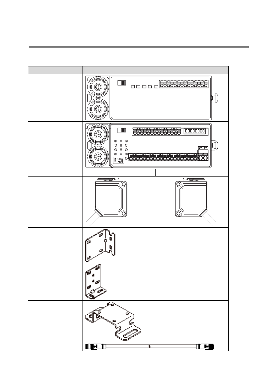
The ST4 system can be built up from the following parts. Which controller type you choose
depends on your requirements and applications.
Part name Part
Controller ST4-C11
Multifunctional Controller
ST4-C12EX
Emitter ST4-A and
Receiver ST4-A
Emitter Receiver
Back angled mounting
bracket (optional)
Foot angled mounting
bracket (optional)
Foot biangled protective
mounting bracket
(optional)
Extension cable ST4-CCJ
9
Page 18
Before Using this Device
Part name Part
(optional)
Branch cable
ST4-CCJ-WY (optional)
Slit mask (optional)
Panasonic ST4 Instruction Manual
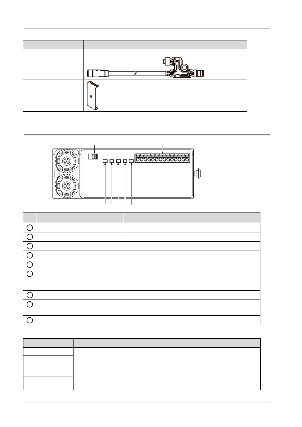
2.2.1 Elements of the Controller ST4-C11
3
2
1
456 7 8
Identifier Function
Emitter connector Connects the emitter of the ST4-A.
1
Receiver connector Connects the receiver of the ST4-A.
2
Output polarity selection switch Switches the control output to PNP output or NPN output.
3
Power indicator (Green) Lights up while power is ON.
4
Control output indicator (Green) Lights up while the control output (OSSD 1/2) is ON.
5
Interlock indicator (Yellow) Lights up while the interlock is ON.
6
Emission halt indicator (Orange) Lights up while the emission halt function is valid.
7
Fault indicator Lights up or blinks when an error occurs.
8
Terminal block See the following table.
9
Turns OFF when an error occurs or the control output (OSSD
1/2) is ON.
For details, refer to "Troubleshooting (see page
9
79)".
Terminal block
Terminal name Description
IL+
IL-
IU+
IU-
10
Interference prevention terminals (downstream)
For details, refer to "Interference Prevention Function see "
Function" on page
Interference prevention terminals (upstream)
For details, refer to Interference Prevention Function see "
Function" on page
54".
Interference Prevention
Interference Prevention
54.
Page 19
Panasonic ST4 Instruction Manual
Terminal name Description
X1
X2
X3
T1
T2
AUX
OSSD 1
OSSD 2
A1
A2 0V
Reset input terminals (When X1 and X2 are connected: manual reset, and when X1 and
X3 are connected: auto reset)
Emission halt input terminals
(Open: emission halt, Short-circuit: emission)
Control output (OSSD 1/2)
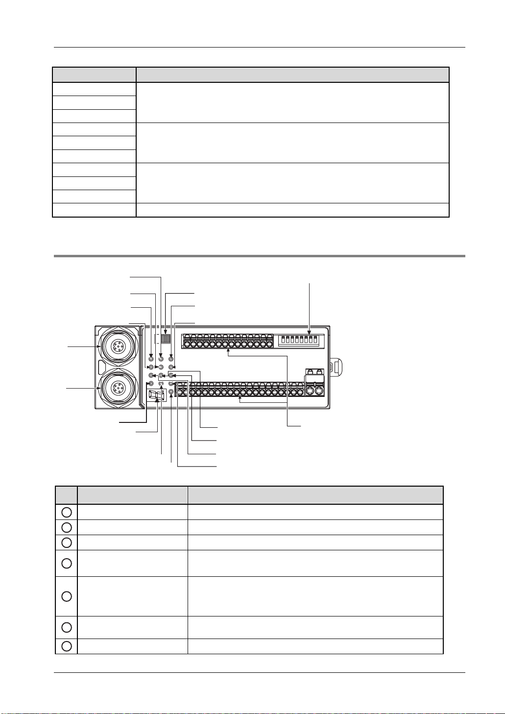
2.2.2 Elements of the Multifunctional Controller ST4-C12EX
2.2 Part Description
w
q
}
{
t
r
e
2
1
3
4
9
0
5
6
Identifier Function
1
Emitter connector Connects the emitter of the ST4-A.
Receiver connector Connects the receiver of the ST4-A.
2
3
Power indicator (Green) Lights up while power is ON.
4
Fault display (Red)
8
7
7-segment lights up when an error occurs.
For details, refer to Troubleshooting (see page
y
u
79).
5
Interlock indicator (Yellow)
Emission halt indicator
6
(Orange)
7
Control output indicator
Lights up while the interlock is ON.
Turns OFF when an error occurs or the control output (OSSD 1/2) is ON.
Lights up while the emission halt function is valid.
Lights up while the control output (OSSD 1/2) is ON.
11
Page 20
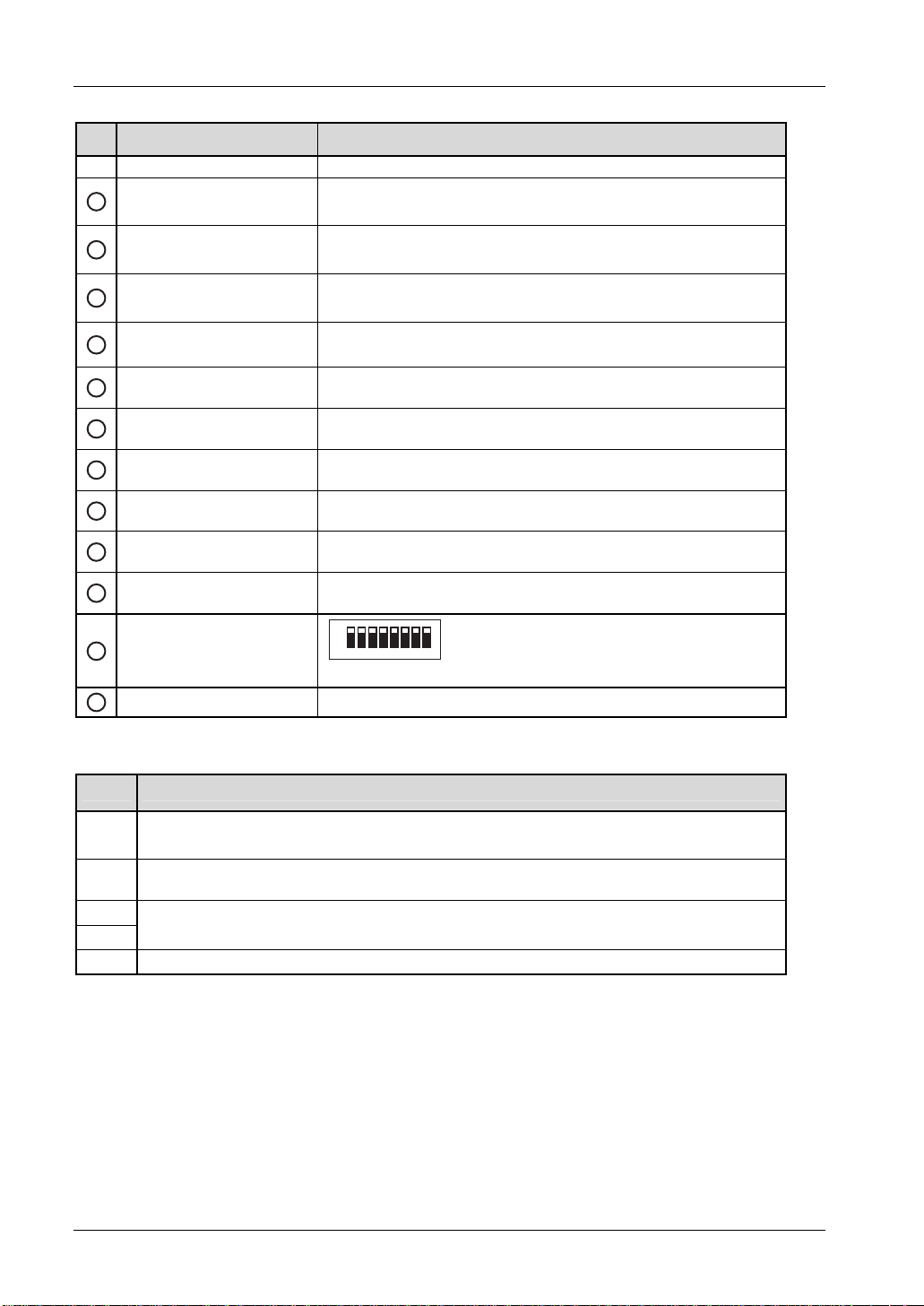
Before Using this Device
Identifier Function
(Green)
Auxiliary output 1 indicator
8
(Orange)
Auxiliary output 2 indicator
9
(Orange)
Auxiliary output 3 indicator
10
(Orange)
Muting input S-A indicator
11
(Orange)
Muting input S-B indicator
12
(Orange)
Muting input S-C indicator
13
(Orange)
Muting input S-D indicator
14
(Orange)
Muting input S-E indicator
15
(Orange)
Muting input S-F indicator
16
(Orange)
Output polarity selection
17
switch
Panasonic ST4 Instruction Manual
Turns OFF while the muting function is valid.
Lights up while the muting function is invalid.
Turns OFF while the override function is valid.
Lights up while the override function is invalid.
Lights up when the muting lamp is in normal operation.
Turns OFF when the muting lamp is in error.
Lights up when the sensor input connected to the muting input terminal
(S-A) is ON
.
Lights up when the sensor input connected to the muting input terminal
(S-B) is ON.
Lights up when the sensor input connected to the muting input terminal
(S-C) is ON.
Lights up when the sensor connected to the muting input terminal (S-D)
is input ON.
Lights up when the sensor input connected to the muting input terminal
(S-E) is ON.
Lights up when the sensor input connected to the muting input terminal
(S-F) is ON.
Switches the control output to PNP output or NPN output.
18
DIP switches
1ON 23456 87
See the table "DIP switches".
Terminal block See table "Terminal block".
19
DIP Switches
No. Description
1 to 4
5
6
7
8 Deactivates the muting lamp diagnosis function (see page 74).
Sets the ST4-A into the muting state.
Sets effective time for muting/override (see page
59).
Checks the states "beam received" and "beam interrupted" of the connected ST4-A, or a sensor
error (see "
Sensor Diagnosis Function (Only ST4-C12EX)" on page 71).
Unused
12
Page 21

Panasonic ST4 Instruction Manual
Terminal block
Terminal Name Description
S+ Muting input power supply (24V)
S-A Muting input S-A (for PNP type)
S-B Muting input S-B (for NPN type)
S- Muting input power supply (0V)
S+ Muting input power supply (24V)
S-C Muting input S-C (for PNP type)
S-D Muting input S-D (for NPN type)
S- Muting input power supply (0V)
S+ Muting input power supply (24V)
S-E Muting input S-E (for PNP type)
S-F Muting input S-F (for NPN type)
S- Muting input power supply (0V)
AUX1 Auxiliary output 1 (muting function)
AUX2 Auxiliary output 2 (override function)
AUX3 Auxiliary output 3 (lamp shutoff)
AUX4 Negative logic of the control output (OSSD 1/2)
OSSD 1
OSSD 2
L1
L2
A
A2
IL+
IL-
IU+
IU-
O1
O2
X1
X2
X3
T1
T2
Control output (OSSD 1/2)
Muting lamp connecting terminals
Interference prevention terminals (downstream)
For details, refer to Interference Prevention Function see "
Function" on page
Interference prevention terminals (upstream)
For details, refer to Interference Prevention Function see "
Function" on page
Override input terminals
Reset input terminals:
When X1 and X2 are connected: manual reset
When X1 and X3 are connected: auto-reset
Emission halt input terminals (open: emission halt, short-circuit: emission)
54.
54.
2.2 Part Description
Interference Prevention
Interference Prevention
13
Page 22
Before Using this Device
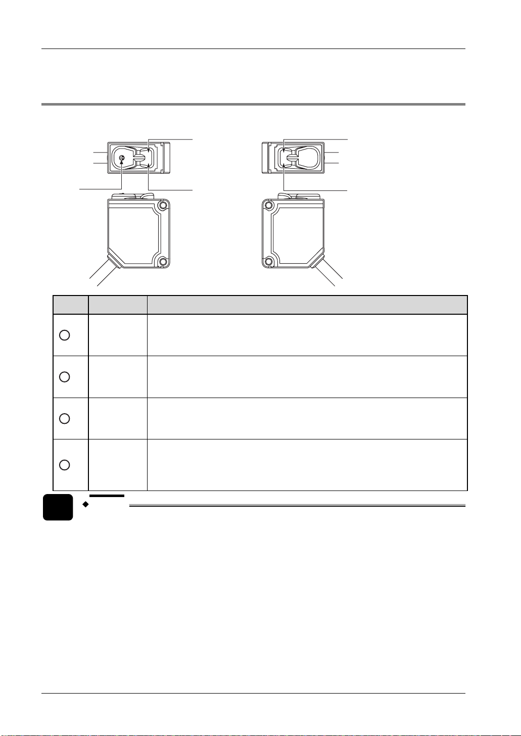
2.2.3 Elements of the Sensor ST4-A
Emitter Receiver
1
Panasonic ST4 Instruction Manual
2
3
1
2
3
4
Identifier Function
Beam
emission
indicator
(Green)
Beam
interruption
indicator
(Red)
Emission
amount
adjuster
(Note 1)
Stable
incident
beam
indicator
(Green)
2
4
Lights up during beam emission of the sensor.
Turns off during emission halt of the sensor.
Lights up during beam interruption of the sensor.
Lights up during lock out.
Turns off during beam reception of the sensor.
Adjusts the emission amount.
For details, refer to Operation Test (see page
Function (see page
Lights up when incident beam intensity is over 150%. (Note 2)
Turns off when incident beam intensity is 150% or less. (Note 2)
57).
46) or Emission Amount Adjustment
14
NOTE
1. Only available with the ST4-A□V type.
2. The incident beam intensity that turns the control output (OSSD 1/2) to ON is
regarded as 100%.
Page 23
Panasonic ST4 Instruction Manual
2.3 Protection Area
2.3.1 Sensing Range
DANGER!
2.3 Protection Area
!
that the operator must pass through the sensing area of the
single beam sensor to reach the dangerous parts of the machine.
Failure to do so can result in death or serious injury.
Do not use any reflection type or recursive reflection type
arrangement.
Installing multiple sets of this device produces a non-sensing
area or causes mutual interference, which may result in death or
Be sure to install a protective structure around the machine so
serious injury.
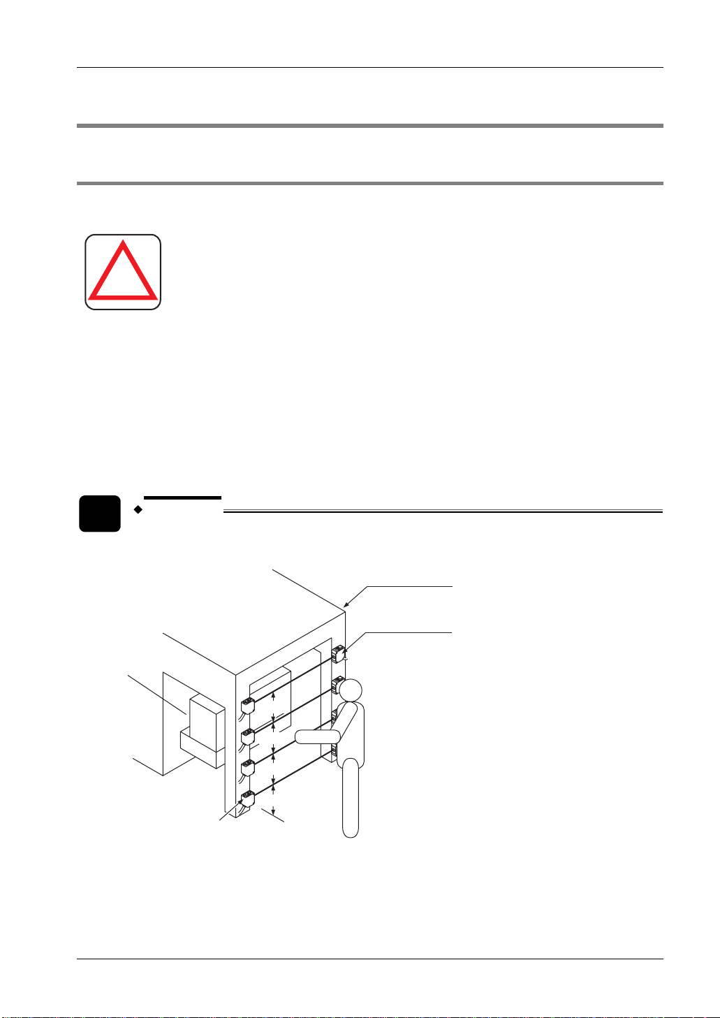
This example shows what a protective structure could be, where the dangerous part of a
machine should be situated and how the emitter and receiver can be arranged.
EXAMPLE
Installing four units of the ST4-A□
Protective structure
Receiver of the
Dangerous
part
ST4-A□
300mm
300mm
300mm
Emitter of the
ST4-A□
300mm
15
Page 24
Before Using this Device
Panasonic ST4 Instruction Manual
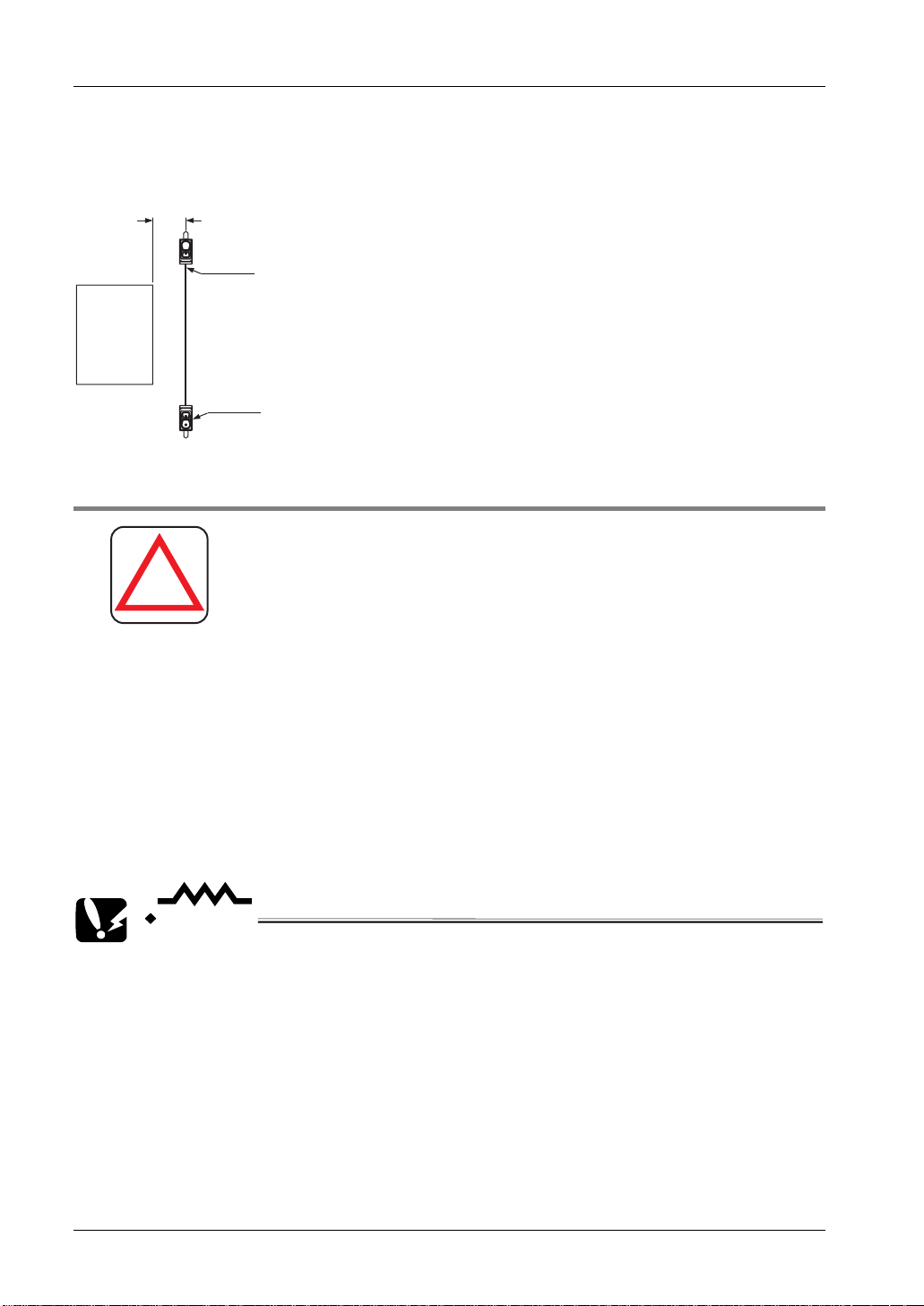
Top view
From the top view the safety distance between the sensing area and the dangerous part is
clearly visible.
Safety distance S (Ds)
Receiver of the
ST4-A□
Dangerous
part
Emitter of the
ST4-A□
2.3.2 Safety Distance
DANGER!
!
Calculate the safety distance correctly, and always
maintain a distance equal to or greater than the safety
distance, between the sensing area of this device and the
dangerous parts of the machine. If the safety distance is
miscalculated or if sufficient distance is not maintained,
the machine will not stop quickly before reaching to the
dangerous parts, which can result in death or serious
injury.
The safety distance is the minimum distance that must be maintained between the ST4-A and
the dangerous parts of the machine so that the machine can be stopped before a human body
or an object can reach the dangerous parts.
The safety distance is calculated based on the equation (see page
17) when a person moves
perpendicular to the sensing area of the area sensor.
CAUTION
• Before designing the system, refer to the relevant standards of the region
where the single beam sensor is to be used.
• The equation should only be used when the intrusion direction is
perpendicular to the sensing area. If the intrusion direction is not
perpendicular to the sensing area, be sure to refer to the relevant standard
(regional standard, specification of the machine, etc.) for details of the
calculation.
16
• The max. response time of the machine is from the point when the machine
receives the halt signal from this device to the point when the dangerous
part of the machine stops. The max. response time of the machine should be
timed with the machine actually used.
Page 25
Panasonic ST4 Instruction Manual
2.3 Protection Area
2.3.2.1 Calculation Example for Europe
The minimum safety distance S is calculated in accordance with EN 999 and ISO 13855 with
the following equation:
S:
K:
T:
C:
S = K x T + C
Safety distance (mm)
Minimum distance required between the sensing area surface and the dangerous
parts of the machine.
Intrusion velocity of operator's body or object (mm/s). The equation assumes an
intrusion direction perpendicular to the sensing area. The recommended value is
1600 mm/s.
+ T
Response time of total equipment (s). T = T
: Maximum halt time of the machine (s). To determine Tm, refer to the
T
m
m
ST4
machine documentation or take a measurement using a special device
called a "brake monitor".
T
: Response time of the safety beam sensor (s).
ST4
Additional distance (mm).
Depending on the height of the beam axis EN 999 recommends different additional
distances as shown in the following table.
Number of beam
axes
Height of beam axis
(e.g. height from the
floor)
Additional distance 1200mm 850mm 850mm 850mm
EXAMPLE
1 2 3 4
750 mm 400mm 300mm 300mm
900mm 700mm 600mm
1100mm 900mm
1200mm
Calculation of the safety distance (S) with the following values and four units of the
ST4-A installed.
K: 1600mm/s
T
: 0.1s
m
T
: 0.025s
ST4
C: 850mm
17
Page 26

Before Using this Device
S = K x T + C
Panasonic ST4 Instruction Manual
= 1600 × (T
m
+ T
) + 850
ST4
= 1600 × (0.1s + 0.025s) + 850
= 1600 × 0.1s
+ 1600 × 0.025 + 850
= 160 + 40 + 850
= 1050
Hence, as per the calculations S is 1050mm.
2.3.2.2 Calculation Example for the US
The safety distance Ds is calculated in accordance with ANSI/RIA 15.06 with the equation:
Ds:
Ds = K × T + D
Safety distance (mm)
Minimum required distance between the sensing area surface and the dangerous
parts of the machine
K:
Intrusion velocity of operator's body or object. The recommended value in OSHA is
63inch/s ( 1600mm/s).
ANSI/RIA 15.06 does not define the intrusion velocity "K." When determining K,
consider possible factors including the physical ability of the operators.
T:
Response time of total equipment (s). T = Ts + Tc + T
T
is the worst stopping time of the machine/equipment
s
T
is the worst stopping time of the control system
c
pf
ST4
18
T
is the response time of the safeguarding device (25ms)
ST4
Dpf:
Additional distance calculated from the size of the minimum sensing object of the
sensor (mm).
REFERENCE
Since the calculation is based on 1 inch = 25.4mm, there is a slight difference
between the representation in mm and that in inches. Refer to the relevant
standard for the details.
Page 27
Panasonic ST4 Instruction Manual
2.3 Protection Area
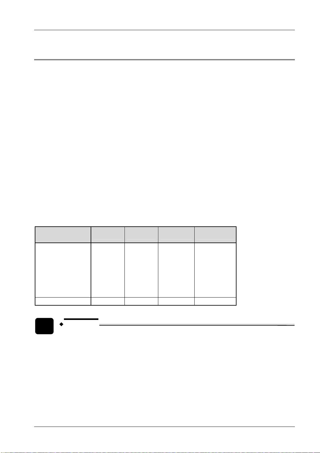
Example calculation of the safety distance for a "REACH OVER" application
Topmost beam axis
35.434 inch (≈ 900mm) or more
11.812 inch (≈ 300mm) or less
Undermost beam axis
The following default values of ANSI/RIA 15.06 are used for the example calculation:
Detectable minimum sensing
object
Undermost beam axis: 11.812inch ( 300mm) or less
Topmost beam axis 35.434inch ( 900mm) or more
T
D
pf
Ds
= K × T + Dpf
Min. 2.52inch ( 64mm) and max. 23.623inch ( 600mm)
0.5s
47.245inch ( 1200mm)
= 63 × T + 47.245
= 63 × 0.5 + 47.245
= 31.5 + 47.245
= 78.745inch
= 2000.123mm
2001mm
Hence Ds = 2001mm.
REFERENCE
Since the calculation is based on 1 inch = 25.4mm, there is a slight difference between the
representation in mm and that in inches. Refer to the relevant standard for the details.
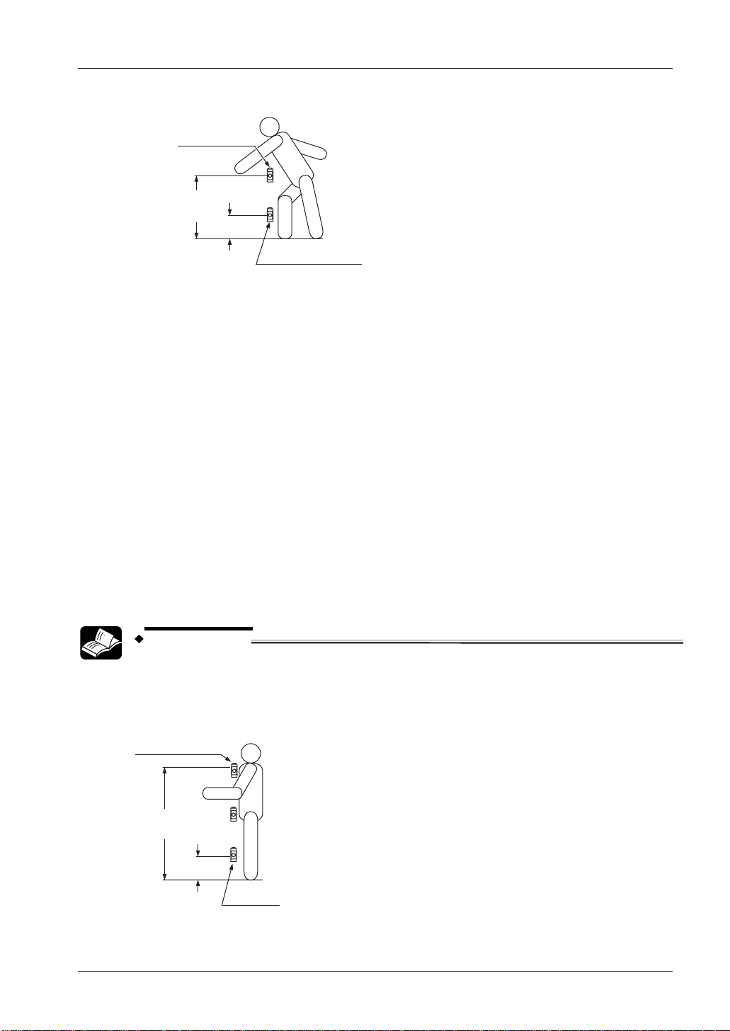
Example calculation of the safety distance for a "REACH THRU" application
Topmost beam axis
47.245 inch
(
≈ 1200mm) or more
11.812 inch
(≈ 300mm) or less
Undermost
beam axis
The following default values of ANSI/RIA 15.06 are used for the example calculation:
19
Page 28
Before Using this Device
Detectable minimum sensing object Min. 2.52inch ( 64mm) and max. 23.623inch ( 600mm)
Undermost beam axis 11.812inch ( 300mm) or less
Topmost beam axis 47.245inch ( 1200mm) or more
T
D
pf
Ds
= K × T + Dpf
0.5s
35.434inch ( 900mm)
Panasonic ST4 Instruction Manual
= 63 × T + 35.434
= 63 × 0.5 + 35.434
= 31.5 + 35.434
= 66.934inch
= 1700.1236mm
1701mm
Hence Ds = 1701mm.
REFERENCE
Since the calculation is based on 1 inch = 25.4mm, there is a slight difference between
the representation in mm and that in inches. Refer to the relevant standard for the
details.
2.3.3 Influence of Reflective Surfaces
DANGER!
!
If a reflective surface exists where this device is to be installed,
make sure to install this device so that reflected light from the
reflective surface does not enter the receiver. Alternatively, take
countermeasures such as painting, masking, roughening, or
changing the material of the reflective surface, etc. Failure to do so
may cause the device not to detect, resulting in serious injury or
death.
20
Page 29
Panasonic ST4 Instruction Manual
2.3 Protection Area
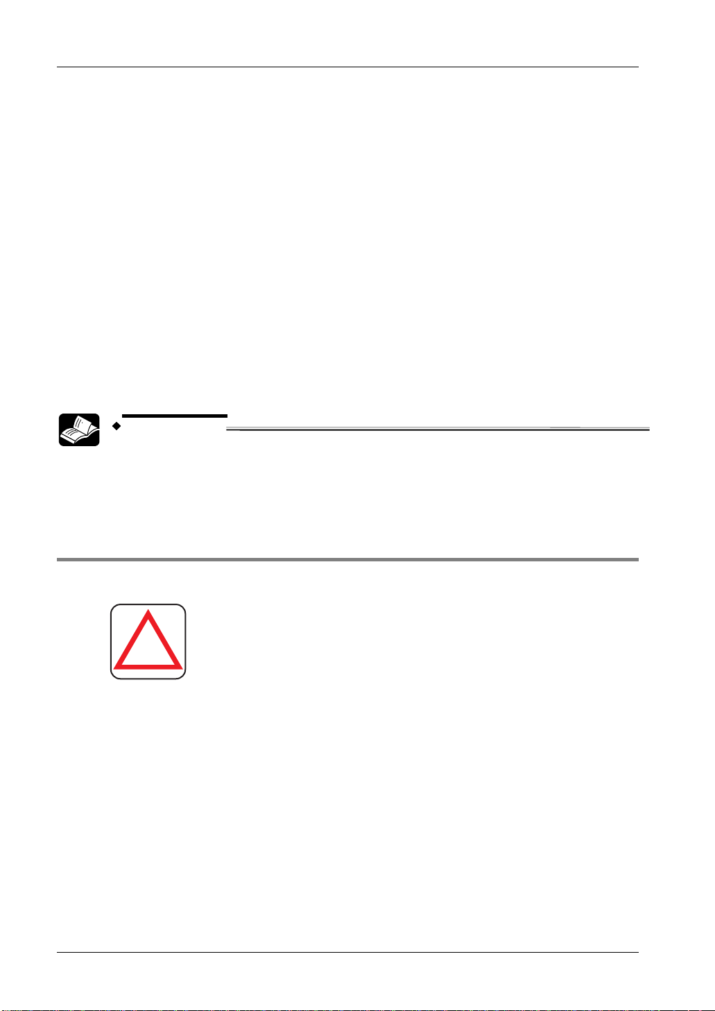
Install this device at a distance of at least A m (provided as follows) away from reflective
surfaces such as metal walls, floors, ceilings, work pieces, covers, panels or glass surfaces.
Side view Top view
Reflective ceiling
Reflective surface
Emitter
A A
Sensing range
A
Reflective floor
Distance between emitter and receiver (sensing
Receiver
L
Emitter
∂°
∂°
Sensing range L
Allowable installation distance A
range L)
0.1 to 3m 0.16m
3 to 15 m L/2 x tan 2 = L x 0.053m ( = 3°)
NOTE
The effective aperture angle for this device is ±2.5° (when L > 3m) as required by
IEC 61496-2/UL 61496-2. However, install this device away from reflective
surfaces, taking into consideration an effective aperture angle of ±3° to account
for beam misalignment during installation.
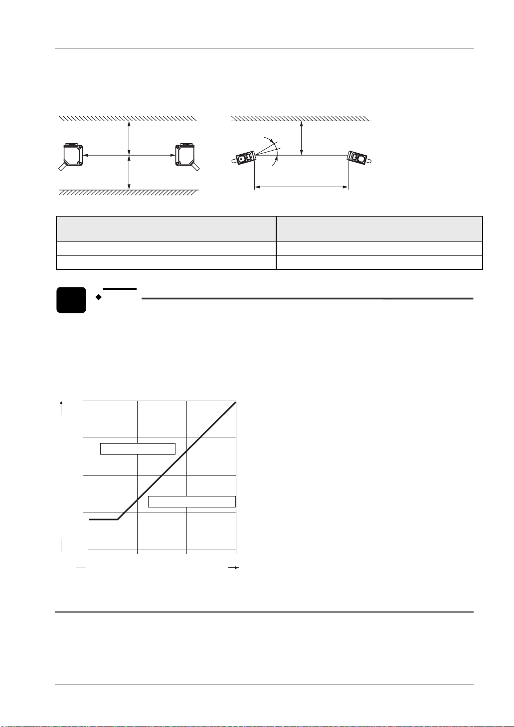
Allowable distance from sensor beam axis to reflective surface
0.8
0.6
Install in this area
0.4
Do not install in this area
0.2
Allowable installation distance A (m)
0 5 10 15
Distance between emitter and receiver L (m)
2.3.4 Placement of Emitter and Receiver
You can install a system in which multiple sets of controllers and their respective sensors face
each other. Use this configuration if there is a problem in wiring or additional equipment has to
be protected. If you arrange multiple sets, perform an operation test (see page
46).
21
Page 30
Before Using this Device
DANGER!
Panasonic ST4 Instruction Manual
!
understand them thoroughly before installation. Improper
placement could cause device malfunction, which can result in
serious injury or death.
If this device is used in multiple sets, avoid mutual interference.
If mutual interference occurs, it can result in serious injury or
death.
Refer to the examples of device placement as follows and
EXAMPLE
Arrangement of the emitter and receiver back to back:
ST4-A□ ST4-A□
EmitterReceiver
ST4-C11
ST4-C12EX
or
Emitter
Receiver
Arrangement of the emitter and receiver vertically on opposite sides:
22
ST4-A□
Emitter Receiver
Receiver
ST4-A□
Emitter
ST4-C11
or
ST4-C12EX
ST4-C11
or
ST4-C12EX
Page 31

Panasonic ST4 Instruction Manual
Arrangement of the emitter and receiver horizontally on opposite sides
2.3 Protection Area
Receiver
Emitter
ST4-A□
or
Emitter
ST4-A□
Receiver
ST4-C11
ST4-C12EX
Installation of a barrier
ST4-A□
NOTE
ReceiverEmitter
Barrier
ST4-C11
ST4-C12EX
Emitter
or
ST4-A□
Receiver
The preceding arrangements are just examples of device placement. If there are
any questions or problems, please contact our office.
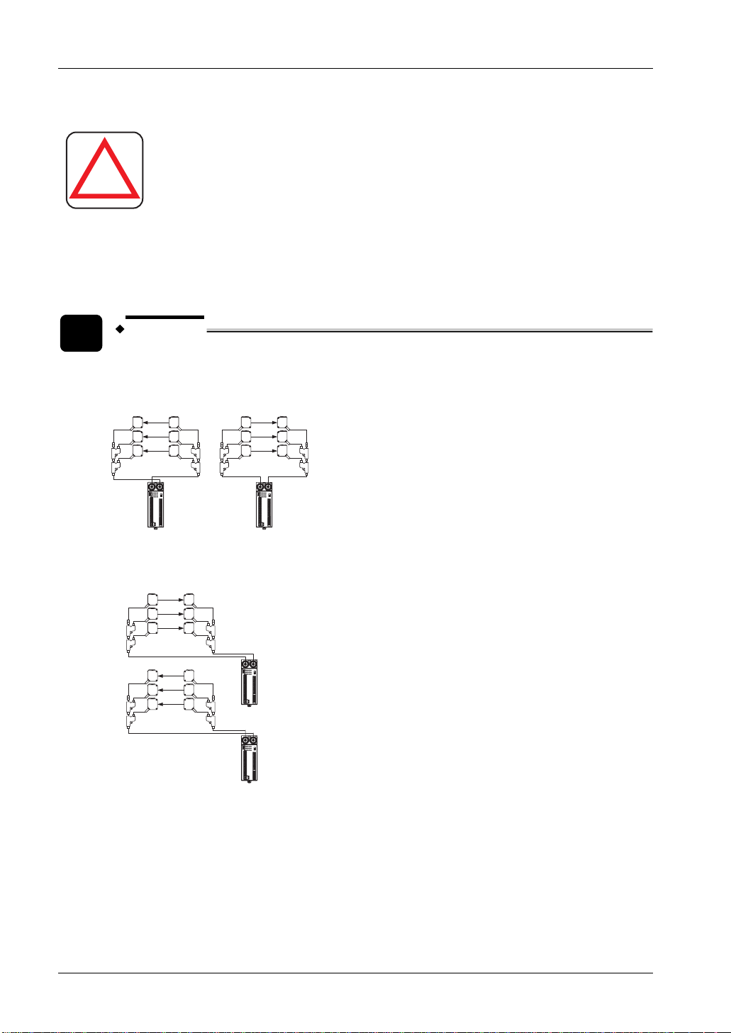
2.3.5 Connecting Multiple Sensors Heads
You can connect up to six units of the ST4-A per controller.
The cable length between all emitters and the controller, as well as between all receivers and
the controller, must not exceed 50m, respectively.
23
Page 32

Before Using this Device
DANGER!
Panasonic ST4 Instruction Manual
!
emitters and receivers, the device will not operate properly. This
may result in serious injury or death.
The cable length between all emitters and the controller, as well
as between all receivers and the controller, must not exceed
50m, respectively. If this length is exceeded it leads to improper
operation of the device, resulting in serious injury or death.
If you hook up the connectors incorrectly or mix connecting the
EXAMPLE
Six sensor units can be connected, whereas the following cables are used:
A1 + A2 + A3 + A4 + A5 + A6 + B1 + B2 + B3 + B4 + B5 + B6
Emitter of Receiver of
A6
A5
A4
B6
B5
B4
B3
ST4-A□
S6
S5
S4
S3
S6
S5
S4
S3
ST4-A□
B6
B5
B4
B3
A6
A5
A4
1.
2.
24
A3
A2
Branch cable
ST4-CCJ05-WY
(Optional)
B2
B1
A1
Extension cable
ST4-CCJ□
(Optional)
S2
S1
S2
S1
ST4-C11
ST4-C12EX
B2
B1
A1
or
A3
A2
3.
Procedure
1. Insert the male emitter connector of the ST4-A□ (color: gray) into the female
emitter connector of the controller (color: gray).
2. Insert the male receiver connector of the ST4-A□ (color: black) into the
female receiver connector of the controller (color: black).
Page 33

Panasonic ST4 Instruction Manual
3. Make sure to use the optional exclusive cable (ST4-CCJ□, ST4-CCJ05-WY)
for wiring, and match the connector colors (gray: emitter, black: receiver).
4. After installing the ST4-A□, check that the ST4-A□ detects a part of human
body before it reaches to the dangerous part of the machine, by watching the
beam interruption indicator (red).
2.3 Protection Area
5. Check that the ST4-A□ is installed in the proper position.
2.3.6 Address Allocations of the Sensor ST4-A□
When connecting multiple units of the ST4-A, addresses are automatically allocated to the
newly connected units of the ST4-A, beginning with the unit closest to the controller.
The corresponding emitter and receiver have the same address (see following example).
The automatic interference prevention function is based on the address of the sensors.
CAUTION
Ensure that the emitter and the receiver operate only in combination with the
same address.
EXAMPLE
25
Page 34

Before Using this Device
Connection example 1: No branching between the ST4-A and the ST4-CCJ05-WY
when six units are connected
Panasonic ST4 Instruction Manual
Branch cable
ST4-CCJ05-WY
(Optional)
Emitter of
6
5
4
3
2
1
Extension cable
ST4-CCJ□
(Optional)
ST4-A□
Address 6
Address 5
Address 4
Address 3
Address 2
Address 1
Receiver of
Address 6
Address 5
Address 4
Address 3
Address 2
Address 1
ST4-C11
ST4-C12EX
ST4-A□
6
5
4
3
2
1
or
NOTE
Addresses are automatically allocated in the order of the arrows shown in the
preceding figure.
26
Page 35

Panasonic ST4 Instruction Manual
EXAMPLE
Connection example 2: Branching between the ST4-A and ST4-CCJ05-WY when six
units are connected
2.3 Protection Area
Branch cable
ST4-CCJ05-WY
(Optional)
6
5
3
2
1
Extension cable
ST4-CCJ□
(Optional)
Emitter of
4
ST4-A□
Address 6
Address 5
Address 4
Address 3
Address 2
Address 1
Address 6
Address 5
Address 4
Address 3
Address 2
Address 1
ST4-C11
ST4-C12EX
Receiver of
4
or
ST4-A□
6
5
3
2
1
NOTE
• Addresses are automatically allocated in the order of the arrows shown in
the preceding figure.
• Addresses of the ST4-A□ are allocated in the order of the numbers that are
marked on the main body of ST4-CCJ05-WY (optional).
27
Page 36

Before Using this Device
• Connect the ST4-A□s to the connector numbers 2 and 3 of the branch cable
ST4-CCJ05-WY (optional). If the ST4-A□s are not connected to the
connectors 2 and 3, the device will not operate properly. For an unconnected
condition, the fault indicator (yellow) of ST4-C11 blinks once. For
ST4-C12EX, "
Panasonic ST4 Instruction Manual
" is indicated on the fault display (red).
2
1
3
28
Page 37

Panasonic ST4 Instruction Manual
2.4 Mounting and Removing
2.4.1 Mounting and Removing the Controller
The controller can be mounted on a 35mm width DIN rail.
2.4 Mounting and Removing
1.
2.
3.
Procedure
1. Push the DIN rail stopper.
2. Fit the tab on the opposite side of the DIN rail stopper onto the DIN rail.
3. Press the device into place.
2
Remove the controller.
1.
2.
3.
Procedure
1. Insert a flathead screwdriver into the groove of the DIN rail stopper and pull
out the stopper.
2. Push the controller in the opposite direction.
DIN rail stopper
1
3
35mm width DIN rail
3. Lift and remove the controller.
1
3
2
1
CAUTION
Removing the controller without unlocking the DIN rail stopper may cause the
tabs to break.
29
Page 38

Before Using this Device
Panasonic ST4 Instruction Manual
2.4.2 Mounting the Sensor ST4-A□
Select the sensor mounting bracket based on the installation environment. The mounting
bracket is not included with this device. Please purchase the optional sensor mounting bracket
that fits with the mounting environment.
DANGER!
!
After installing the ST4-A□, check that the ST4-A□ detects a part
of human body before it reaches to the dangerous part of the
machine, by watching the beam interruption indicator (red).
Also check that ST4-A□ is installed in a proper position.
CAUTION
• Do not apply an improper load such as forcibly bending the cable of the
single-beam sensor, because the wire could break.
• The minimum bending radius of the cable is R5mm. When mounting,
consider the cable bending radius.
The following procedure shows the mounting of the single-beam sensor with the mounting
bracket MS-CX1.
NOTE
• Mount the emitter and the receiver at the same level and parallel to each
other. The effective aperture angle of this device is ±2.5° or less for a sensing
distance of 3m or more.
• In preparation for mounting, prepare mounting holes on the mounting
surface (see "
Dimensions" on page 95).
1.
2.
30
3.
Procedure
1. Mount the sensor with the M3 screws with washers (length 12mm) attached
to the sensor mounting bracket (optional).
Page 39

Panasonic ST4 Instruction Manual
The tightening torque should be 0.5N·m or less.
2. Mount the sensor on the mounting surface with M3 screws with washers.
2.4 Mounting and Removing
2.4.3 Connecting Controller and Sensor ST4-A□
DANGER!
!
The emitter of the ST4-A (connector color: gray) has to be connected with the emitter
connector of the controller (connector color: gray). The receiver of the ST4-A (connector color:
black) has to be connected with the receiver connector of the controller (connector color: black).
CAUTION
• Make sure to turn OFF the power before connecting disconnecting the
cables.
• Securely tighten by hand the fixing ring on the emitter or receiver of the
ST4-A□.
If you hook up the connectors incorrectly or mix connecting the
emitters and receivers, the device will not operate properly. This
may result in serious injury or death.
• If the fixing ring on the emitter/receiver of the ST4-A□ is tightened with pliers,
the connector may be damaged.
• If the tightening torque is insufficient, the fixing ring on the emitter or
receiver of the ST4-A□ may loosen due to vibrations, etc.
31
Page 40

Before Using this Device
Connecting the single-beam sensor with the controller:
Panasonic ST4 Instruction Manual
1.
2.
3.
Procedure
1. Insert the male connector of the ST4-A□ in connector of the controller.
2. Turn the fixing ring to tighten.
Fixing ring
Disconnecting
1.
2.
3.
Procedure
1. Loosen the fixing ring.
2. Pull out the connector by holding the fixing ring.
Emitter connector of the controller
Receiver connector of the controller
Connector of
ST4-A□
Fixing ring
CAUTION
• Before removing the connectors, make sure that the fixing rings are fully
loosened.
• If the connectors are forcibly pulled out with the fixing rings tightened, the
connectors may be damaged.
2.4.4 Series Connection of the Sensor ST4-A□
You can connect up to six units of the ST4-A per controller in series.
When connecting several sensors, the extension cable ST4-CCJ (optional) and the branch
cable ST4-CCJ05-WY (optional) are needed. Please purchase them separately.
32
Page 41

Panasonic ST4 Instruction Manual
DANGER!
2.4 Mounting and Removing
!
The emitter of the ST4-A (connector color: gray) has to be connected with the emitter
connector of the controller (connector color: gray). The receiver of the ST4-A (connector color:
black) has to be connected with the receiver connector of the controller (connector color: black).
• Addresses of the ST4-A□ are allocated in the order of the numbers that are
• Connect the ST4-A□s to the connector numbers 2 and 3 of the branch cable
If you hook up the connectors incorrectly or mix connecting the
emitters and receivers, the device will not operate properly. This
may result in serious injury or death.
The cable length between all emitters and the controller, as well
as between all receivers and the controller, must not exceed
50m, respectively. If this length is exceeded it leads to improper
operation of the device, resulting in serious injury or death.
After installing the ST4-A□, check that the ST4-A□ detects a part
of human body before it reaches to the dangerous part of the
machine, by watching the beam interruption indicator (red). Also
check that ST4-A□ is installed in a proper position.
NOTE
marked on the main body of ST4-CCJ05-WY (optional).
ST4-CCJ05-WY (optional). If the ST4-A□s are not connected to the
connectors 2 and 3, the device will not operate properly. For an unconnected
condition, the fault indicator (yellow) of ST4-C11 blinks once. For
ST4-C12EX, "
" is indicated on the fault display (red).
2
1
3
To connect the sensor in series, you need at least two sets of receiver and emitter of the
ST4-A, two extension cables ST4-CCJ□s and two branch cables ST4-CCJ05-WY.
1.
2.
3.
Procedure
33
Page 42

Before Using this Device
1. Insert the male connectors of the extension cables ST4-CCJ□s into the
connector of the controller, and turn the fixing ring to fix.
2. Insert connector no. 1 of the branch cables ST4-CCJ05-WY into the female
connectors of both extension cables ST4-CCJ□, and tighten the fixing ring.
Emitter connector of
the controller
Receiver connector
of the controller
Male connector of
ST4-CCJ□
Fixing ring
Panasonic ST4 Instruction Manual
Female
connector of
ST4-CCJ□
Fixing ring
Connector 1 of
ST4-CCJ05-WY
3. Insert the connector of the ST4-A□ into connector no. 2 of the branch cable
ST4-CCJ05-WY, and tighten the fixing ring.
ST4-A
K
Connector 2 of
Connector of
Fixing ring
ST4-CCJ05-WY
Fixing ring
4. Insert the connector of the second set of the ST4-A□ into connector no. 3 of
the branch cable ST4-CCJ05-WY, and tighten the fixing ring. If you want to
connect further sensors, insert connector no.1 of the third and fourth branch
cable ST4-CCJ05-WY to the connector no. 3 of first and second branch cable,
and tighten the fixing rings. After that, repeat the procedures 3 and 4.
Connector 3 of
Fixing ring
ST4-CCJ05-WY
Connector of
ST4-A□
34
Fixing ring
5. Use a M5 small pan head screw (please arrange separately) to mount
ST4-CCJ05-WY.
Page 43

Panasonic ST4 Instruction Manual
The tightening torque should be 0.7N·m or less.
M5 small pan
head screw
To remove the sensor:
2.4 Mounting and Removing
1.
2.
3.
Procedure
1. Loosen the fixing ring.
2. Pull out the connector by holding the fixing ring.
Fixing ring
Connector
CAUTION
• Before removing the connector, make sure that the fixing ring is fully
loosened. If the connector is forcibly pulled out with the fixing ring tightened,
the connector may be damaged.
35
Page 44

Before Using this Device
Panasonic ST4 Instruction Manual
2.5 Wiring
Read the following warnings carefully before wiring.
DANGER!
!
Switch off the power before wiring the device.
All electrical wiring should conform to the regional electrical
regulations and laws. The wiring should be done by engineer(s)
having the required electrical knowledge.
Do not run the sensor cable together with high-voltage lines or
power lines or put them together in the same raceway.
Take countermeasures regarding the system to ensure that
dangerous performance caused by the earth failure cannot
occur. Failure to do so could cause jeopardize the system stop,
resulting in serious bodily injury or death.
In order that the output is not turned ON due to earth fault of
control output (OSSD 1/2) terminal, be sure to ground to the 0V
side for PNP output or the 24V side for NPN output.
2.5.1 Power Supply Unit
The wiring of the power supply unit should be performed by a specialist who has the required
electrical knowledge.
NOTE
Use a safety relay unit or an equivalent control safety circuit for FSD.
DANGER!
!
The DC power supply unit must satisfy the following conditions.
• The power supply unit must be authorized for use in the region where this device is to be
used.
• The power supply unit must conform to the EMC Directive and Low-Voltage Directive
36
Wire correctly and use a power supply unit which conforms to
the laws and standards of the region where this device is to be
used. If the power supply unit does not conform to regional
requirements or the wiring is improper, may malfunction or be
damaged, which can result in serious injury or death.
Page 45

Panasonic ST4 Instruction Manual
2.5 Wiring
(where CE certification is required). The power supply unit must conform to CLASS 2
(where UL/cUL certification is required).
• If the power supply conforms to the Low-Voltage Directive and has an output of 100VA
or less, it is suitable.
• The frame ground (F.G.) terminal must be connected to ground when using a
commercially available switching regulator.
• The power supply unit must have an output holding time of 20ms or more.
• If there is a possibility of surge, take countermeasures such as connecting a surge
absorber to the origin of the surge.
2.5.2 I/O Circuit Diagrams
The following diagrams show the circuits of the controller and the wiring for different functions
and parts of the system.
2.5.2.1 Circuit of Controller ST4-C11
Controller ST4-C11
PNP output
24V
A1
3
Ui
2
A2
0V
1
= Main circuit
2
= Emitter side
3
= Receiver side
4
= Output polarity switch
5
= Emission halt input
PNP
NPN
4
1
X1 X2
Reset
KA
X3
T1
5
T2
AUX
IU+ IU- IL+ IL-
OSSD1
OSSD2
KAKBKB
0V
37
Page 46

Before Using this Device
NPN output
24V
A1
3
PNP
4
X1
X2
Reset
KA
KB
X3
Panasonic ST4 Instruction Manual
IU+ IU- IL+ IL-
AUX
NPN
Ui
1
2
A2
0V
T1
T2
5
1
= Main circuit
2
= Emitter side
3
= Receiver side
4
= Output polarity switch
5
= Emission halt input
2.5.2.2 Circuit of Multifunctional Controller ST4-C12EX
NOTE
KA and KB are the external devices (forcibly guided relay or magnetic
contactor).
OSSD1
KA
OSSD2
KB
24V
Multifunctional Controller ST4-C12EX
PNP output
Output polarity
selection switch
PNP
PNP
NPN
NPN
S-AS+ S-B S- S-CS+ S-D S- S-ES+
(PNP output type)
Muting input
X1 X2 X3
Main circuit
Muting sensor
Muting sensor
(NPN output type)
Receiver side
Emitter side
38
24V
A1
A2
0V
Reset
KA
KB
S-F S- T2T1 O1 O2 L2L1
OUT
+V
PLC etc.
AUX2AUX1 AUX3 AUX4
0V
Emission
halt input
Override input Muting lamp
IU-IU+ IL+ IL-
OSSD1 OSSD2
KA KB
0V
Page 47

Panasonic ST4 Instruction Manual
NPN output
2.5 Wiring
Receiver side
Emitter side
24V
A1 X1 X2 X3
A2
0V
NOTE
Output polarity
selection switch
PNP
NPN
S-AS+ S-B S- S-CS+ S-D S- S-ES+
Main circuit
Muting sensor
(PNP output type)
Muting input
Muting sensor
(NPN output type)
Reset
KA
KB
S-F S- T2T1 O1 O2 L2L1
OUT
+V
PLC, etc.
AUX2AUX1 AUX3 AUX4
0V
Emission
halt input
Override input Muting lamp
IU-IU+ IL+ IL-
OSSD1 OSSD2
KA KB
24V
• KA and KB are the external devices (forcibly guided relay or magnetic
contactor).
• When using the normally open (NO) contact switch as a
S-AS+S-B S-
muting sensor, wire as shown right.
2.5.2.3 Manual and automatic reset
By wiring the reset input terminals (X1, X2, and X3) as shown, you can select a manual or an
automatic reset, with or without back check.
Manual reset
When the back check circuit is
needed:
Reset
KA
KB
X2 X3
X1
Automatic reset
When the back check circuit is
needed:
KA
X1 X2 X3
KB
When the back check circuit is not
needed:
Reset
X1
X2
X3
When the back check circuit is not
needed:
X1 X2 X3
39
Page 48

Before Using this Device
Panasonic ST4 Instruction Manual
2.5.2.4 Emission Halt Input Terminals
The internal circuits of the emission halt input terminals (T1 and T2) as well as the override input
terminals (O1 and O2) are switched by the output polarity selection switch.
Controller ST4-C11
PNP output NPN output
3kΩ
1
1
3kΩ
T1
1
= Main circuit
T2
T1
T2
Controller ST4-C12EX
PNP output NPN output
1
T1
T2 O1 O2
1
= Main circuit
3kΩ3kΩ
1
T1
T2 O1 O2
3kΩ3kΩ
Output waveform (control output OSSD 1/2 ON)
Since the controller performs a self-diagnosis of the output circuit when the sensor is in light
receiving status (ON), the output transistor periodically turns OFF (see following figure). If the
preceding OFF signal is received by the controller the output circuit is judged as normal. If the
OFF signal is not received, the controller judges either the output circuit or wiring as faulty, and
the control output (OSSD 1/2) switches OFF.
CAUTION
Since the OFF signal of this device might cause malfunction, ensure that the
input response time of the machine corresponds to the requirements of this
device.
ON
OSSD 1
OFF
ON
OSSD 2
OFF
30 - 50μs
The values in the preceding picture are approximate values.
50 - 100μs
11m s
30 - 50μs
30 - 50μs
120μs
50 - 100μs120μs
30 - 50μs
40
Page 49

Panasonic ST4 Instruction Manual
2.5 Wiring
2.5.3 Connecting to the Terminal Block
For the connection with the terminal block of the controller, insert a solid wire or twisted wire
(lead wire) with a ferrule into the hole till it stops. The wire is locked when properly inserted.
Flathead
screwdriver
Lead wire
Ferrule (sleeve) terminal
Release button
When connecting a twisted wire (lead wire) without a ferrule, insert the wire to the innermost of
the terminal hole while pressing the release button.
If you want to release the solid wire or the twisted wire (lead wire), pull the wire while pressing
the release button.
CAUTION
However, do not pull the wire with excessive force, as this can cause a cable
break.
The following wires are recommended:
2
• Terminal block connector: 0.2 to 1.5mm
• Power supply side connector (A1, A2) (ST4-C12EX only): 0.2 to 2.5mm
(AWG 24 to 16)
2
(AWG 24 to
12)
2.5.4 Terminal Arrangement Diagram
The following tables list the terminals of the controllers ST4-C11 and ST4-C12EX.
Controller ST4-C11
Terminal name Description
IL+
IL-
IU+
IU-
X1
X2
X3
Interference prevention terminals (downstream)
For details, see "
54.
page
Interference prevention terminals (upstream)
For details, see "
54.
page
Reset input terminals:
• When X1 and X2 are connected: manual reset
Interference Prevention Function" on
Interference Prevention Function" on
• When X1 and X3 are connected: auto-reset
41
Page 50

Before Using this Device
Panasonic ST4 Instruction Manual
Terminal name Description
Multifunctional Controller ST4-C12EX
T1
T2
AUX
OSSD 1
OSSD 2
A1
A2
Emission halt input terminals
(Open: emission halt, Short-circuit: emission)
Negative logic of the control output (OSSD 1/2)
Control output (OSSD 1/2)
24V DC
0V
Terminal
name
S+
S-A
S-B
S-
S+
S-C
S-D
S-
Muting
Pattern
Setting
Switch
S+
S-E
S-F
SAUX1
AUX2
AUX3
AUX4
OSSD 1
OSSD 2
L1
L2
A1
A2
Muting input power supply 24V
Muting input S-A for PNP output type sensor
Muting input S-B for NPN output type sensor
Muting input power supply 0V
Muting input power supply 24V
Muting input S-C (for PNP type)
Muting input S-D (for NPN type)
Muting input power supply 0V
Muting input power supply 24V
Muting input S-E for PNP type
Muting input S-F for NPN type
Muting input power supply 0V
Auxiliary output 1 (muting function)
Auxiliary output 2 (override function)
Auxiliary output 3 (lamp shutoff)
Negative logic of the control output (OSSD 1/2)
Control output (OSSD 1/2)
Muting lamp connecting terminal
24V DC
0V
Description
42
Terminal
name
IL+
IL-
IU+
IU-
Description
Interference prevention terminals (downstream)
For details, see "
54.
page
Interference prevention terminals (upstream)
For details, see "
54.
page
Interference Prevention Function" on
Interference Prevention Function" on
Page 51

Panasonic ST4 Instruction Manual
2.5 Wiring
Terminal
Description
name
O1
O2
X1
X2
X3
T1
T2
Override input terminals
Reset input terminals:
• When X1 and X2 are connected: manual reset
• When X1 and X3 are connected: auto-reset
Emission halt input terminals:
• Open: emission halt
• Short-circuit: emission
43
Page 52

Before Using this Device
2.6 Adjustment and Operation
2.6.1 Beam-Axis Alignment
Panasonic ST4 Instruction Manual
1.
2.
3.
Procedure
1. Turn ON the power supply unit of this device.
2. Check that the fault indicator (yellow) of the ST4-C11 or the fault display (red)
of the ST4-C12EX is OFF.
If the following error occurs, see "
possible countermeasures to the maintenance staff in charge.
- ST4-C11: The fault indicator (yellow) lights up or blinks
- ST4-C12EX: An error is indicated on the fault display (red).
3. Move the emitter of the ST4-A□ vertically and horizontally in order to
determine the range of light received with the help of the beam interruption
indicator (red). Then fix the emitter in the center of this range.
The tightening torque should be 0.5N·m or less.
Loosen the M3 screws slightly between the ST4-A and the sensor mounting
bracket (optional) to adjust the angle vertically.
Also, loosen the M3 screws slightly between the sensor mounting bracket and the
mounting surface to adjust the angle horizontally.
Troubleshooting" on page 79 and report it and
44
1
2
1
3
1
= M3 screws with washers
2
= Vertical adjustment
3
= Horizontal adjustment
For detailed information of the various sensor mounting brackets, refer to
Dimensions (see "
4. As you did for the emitter, perform the angular adjustment for the receiver of
the ST4-A□.
5. Check that the beam interruption indicators (red) on the emitter and the
receiver of the ST4-A□ are turned OFF. Also check that the stable incident
beam indicator (green) of the receiver lights up.
Dimensions" on page 95) to adjust the angle.
Page 53

Panasonic ST4 Instruction Manual
When adjusting the angle between the emitter and the receiver of the ST4-A,
remember where the beam interruption indicators (red) of the emitter and the
receiver turn OFF (both vertically and horizontally), and adjust the beam-axis to the
position roughly in the center of the range. This makes detection more stable.
Vertical angle adjustment
2.6 Adjustment and Operation
1
3
3
1
= Emitter
2
= Receiver
3
= Range where interruption indicators (red) turn off
2
Horizontal angle adjustment
1
3
3
1
= Emitter
2
= Receiver
3
= Range where interruption indicators (red) turn off
2
45
Page 54

Before Using this Device
2.6.2 Operation Test
DANGER!
Panasonic ST4 Instruction Manual
!
To test the installation:
1.
2.
3.
Procedure
1. Turn ON the power supply unit of this sensor.
2. Check that the fault indicator (yellow) of the ST4-C11 or the fault display (red)
The emission amount adjuster of the ST4-A□V is used to
reduce the beam emission of the ST4-A□V to prevent
influencing other sensors.
Do not use the emission amount adjuster of the ST4-A□V to
prevent the reflection off surfaces. If it is used for such
purposes and the emission amount adjuster is set at MAX.,
the reflection off surfaces increases. This may disable the
sensor from detecting objects, which could result in serious
injury or death.
To cope with reflective surfaces, see "
Surfaces" on page
of the ST4-C12EX are OFF.
If the following error occurs, see (see "
and possible countermeasures to the maintenance staff in charge.
- ST4-C11: The fault indicator (yellow) lights up or blinks
Influence of Reflective
20 .
Troubleshooting" on page 79) and report it
46
- ST4-C12EX: An error is indicated on the fault display (red).
3. When using the ST4-A□V, turn the emission amount adjuster on the emitter
of the ST4-A□V to the position at MAX. side.
1
1
= Emission amount adjuster
4. Check that the ST4-A□ is in the light beam received condition.
5. Check that the beam interruption indicators (red) on the emitter and receiver
of the ST4-A□ light up by interrupting the light beam between the emitter and
the receiver of the ST4-A□ by hand. Also, check that the control output
indicator (green) on the controller is off.
Page 55

Panasonic ST4 Instruction Manual
2.6 Adjustment and Operation
In case that even if the light beam between the emitter and the receiver of the
ST4-A is interrupted and the beam interruption indicator (red) on the
emitter/receiver on the ST4-A does not light up, or the control output indicator
(green) on the controller does not turn off, see (see "
Troubleshooting" on page 79)
and report the symptoms to the maintenance staff in charge.
NOTE
If the indicators show reception of the light beam even though the beam is
interrupted by hand, check whether there is a reflective object or extraneous
light source near the sensor.
2.6.3 Operation
This device starts operation two seconds after the power is on. Configure the control system
accordingly!
Power supply
Emission
condition
Reset input
Beam received
condition
Control output
(OSSD 1 / 2)
Timing chart for operation with manual reset
Stromversorgung
Emissionsstatus
Empfangsstatus
Schaltausgang
(OSSD 1 / 2)
Timing chart for operation with automatic reset
ON
OFF
Emission
Emission
halt
120ms or more
Open
0V/+V
Beam
received
Beam
interrupted
ON
OFF
EIN
AUS
Emission
Lichtunterbrechung
Strahl
empfangen
Strahl
unterbrochen
EIN
AUS
2s or less
max. 2s
120ms or more
T
ON
T
EIN
T
OFF
T
140ms or less, T
ON:
T
AUS
min. 100ms
T
EIN
: max. 90ms, T
T
ON
25ms or less
OFF:
T
EIN
: max. 25ms
AUS
47
Page 56

Page 57

Chapter 3
Functions
Page 58

Functions
Panasonic ST4 Instruction Manual
3.1 Self-Diagnosis Function
The controllers ST4-C11 and ST4-C12EX are equipped with a self-diagnosis function.
Self-diagnosis is carried out periodically during operation.
In case an abnormality is detected during self-diagnosis, the sensor is immediately put in the
lockout state and the control output (OSSD 1, OSSD 2) turns off. Find and remove the cause of
abnormality (see page
79).
50
Page 59

Panasonic ST4 Instruction Manual
3.2 Reset Operation
3.2 Reset Operation
Reset functionality is incorporated in the controllers ST4-C11 and ST4-C12EX. If the interlock
function is activated for the control output (OSSD 1/2), you can reset the control output manually
or automatically.
Manual and auto reset can be selected by wiring the reset input terminals (X1, X2, and X3)
accordingly.
Terminals Operation
X1-X2 Manual reset
X1-X3 Auto reset
3.2.1 Manual Reset
DANGER!
!
Install the reset switch outside of the dangerous area.
Install the reset switch where the staff in charge can see the
whole dangerous area at all times.
For manual reset, keep the following aspects in mind:
• The control output (OSSD 1/2) is not turned ON automatically even if ST4-A receives
the light beam.
Reset input
Reception
status
Control output
(OSSD 1 / 2)
Open
0V/+V
Beam
received
Beam
interrupted
ON
OFF
25ms or less
• The reset button and the back check circuit (KA, KB) are constructed between X1 and
X2. When the back check circuit (KA, KB) is not required, only the reset button is
constructed.
When the back check circuit is required
KA KB
X1
Reset button
When the back check circuit is not required
X1 X2
Reset button
• The machine restarts at the start-up operation of the external reset button, assuming
120ms or more
140ms or less
X2
51
Page 60

Functions
Panasonic ST4 Instruction Manual
ST4-A receives the light beam.
3.2.2 Auto Reset
DANGER!
!
For automatic reset, keep the following aspects in mind:
• The control output (OSSD 1/2) turns on automatically when ST4-A receives the light
beam.
Reception
status
Control output
(OSSD 1 / 2)
• The back check circuit (KA, KB) is constructed between X1 and X3. When the back
check circuit (KA, KB) is not needed, short-circuit between X1 and X3.
When the back check circuit is required
X1
If the auto-reset function is used and the control output (OSSD
1/2) is stopped, ensure that nothing else, such as a safety relay
unit, executes an auto-restart of the system (EN 60204-1).
Beam
received
Beam
interrupted
25ms or less 90ms or less
ON
OFF
100ms or more
KA KB
X3
52
When the back check circuit is not required
X1 X3
Page 61

Panasonic ST4 Instruction Manual
3.3 Emission Halt Function
WARNING!
3.3 Emission Halt Function
!
result in serious injury or death.
The emission halt input is incorporated in the controllers ST4-C11 and ST4-C12EX. This
function stops the emission process of the ST4-A. You can select whether emission is on or
halted by wiring the terminals T1 and T2 as shown in the following table.
Between T1 and T2 Operation
Open Emission halt
Do not use the emission halt input to stop machinery! This could
During emission halt, the control output (OSSD 1/2) is off and the emission halt indicator
(orange) lights up.
If the machinery is not stopped, the cause may be a malfunction due to extraneous noise or an
abnormality in the control output (OSSD 1/2) or the auxiliary output, also from the machine.
Reset input
Emission halt
input
Emission
condition
Control output
(OSSD 1 / 2)
Time chart for manual reset
Emission
halt input
Emission
condition
Control output
(OSSD 1 / 2)
Time chart for auto reset
Short-circuit Emission
Open
0V/+V
Open
Shortcircuit
Emission
Emission
halt
ON
OFF
Open
0V/+V
Emission
Emission
halt
ON
OFF
40ms or more
40ms or more
25ms or less
40ms or more
25ms or more
120ms or more
140ms or less
40ms or more
90ms or less
53
Page 62

Functions
Panasonic ST4 Instruction Manual
3.4 Interference Prevention Function
The interference prevention function is incorporated in both controllers ST4-C11 and
ST4-C12EX.
3.4.1 Interference Prevention With One Controller
You can connect up to six units of the single beam sensor ST4-A per controller. Mutual
interference can be prevented by the automatic interference prevention function incorporated
into the controller.
ST4-A□
ReceiverEmitter
ST4-C11,
ST4-C12EX
3.4.2 Interference Prevention Function When Using Two or More Controllers
You can connect up to six units of the single beam sensor ST4-A per controller. Mutual
interference can be prevented for a maximum of three controller units.
1.
2.
3.
Procedure
1. Establish interference prevention by connecting the IL+ terminal of the first
controller and the IU+ terminal of the second controller.
2. Connect the IL- terminal of the first controller and IU- terminal of the second
controller.
54
Page 63

Panasonic ST4 Instruction Manual
3. Connect the third controller in the same way.
ST4-A□ ST4-A□ ST4-A□
3.4 Interference Prevention Function
IL+
IL-
ST4-C11, ST4-C12EX ST4-C11, ST4-C12EX ST4-C11, ST4-C12EX
NOTE
IU+
IU-
IL+
IL-
IU+
IU-
You can mix the controllers ST4-C11 and ST4-C12EX.
55
Page 64

Functions
A
Panasonic ST4 Instruction Manual
3.5 Auxiliary Output
The auxiliary output is a non-safety output which is incorporated in the controllers ST4-C11 and
ST4-C12EX. It is reserved for non-safety-related purposes.
3.5.1 Auxiliary Output Operation of Controller ST4-C11
Terminal Auxiliary output operation
AUX Negative logic of the control output (OSSD 1/2)
3.5.2 Auxiliary Output Operation of Controller ST4-C12EX
DANGER!
!
Terminal Auxiliary output operation
AUX1
AUX2
AUX3
AUX4
Reset input
Reception
status
Control output
(OSSD 1 / 2)
uxiliary output
(Negative logic
of OSSD)
could be death or serious injury.
ON when the muting function is invalid. OFF when the muting function is valid.
ON when the override function is invalid. OFF when the override function is valid.
ON when the muting lamp is in the normal condition. OFF when the muting lamp is in an abnormal
condition.
Negative logic of the control output (OSSD 1/2)
Open
0V/+V
Beam
received
Beam
interrupted
ON
OFF
ON
OFF
20ms or less
20ms or less
Do not use the auxiliary output to stop the device. The result
120ms or more
140ms or less
20ms or less
56
Page 65

Panasonic ST4 Instruction Manual
A
Time chart for manual reset
Reception
status
Control output
(OSSD 1 / 2)
uxiliary output
(Negative logic
of OSSD)
Beam
received
Beam
interrupted
ON
OFF
ON
OFF
20ms or less
20ms or less
Time chart for auto-reset
3.5.3 Emission Amount Adjustment Function
DANGER!
3.5 Auxiliary Output
90ms or less
20ms or less
!
reduce the beam emission of the ST4-A□V to prevent
influencing other sensors.
Do not use the emission amount adjuster of the ST4-A□V to
prevent the reflection off surfaces. If it is used for such
purposes and the emission amount adjuster is set at MAX.,
the reflection off surfaces increases. This may disable the
sensor from detecting objects, which could result in serious
injury or death.
The emission amount adjuster of the ST4-A□V is used to
To cope with reflective surfaces, see "
Surfaces" on page
20 .
Influence of Reflective
This function is incorporated in the ST4-AV. It is used to reduce the emission amount so that
the emitted beam of ST4-AV will not be received as extraneous light from the other sensors.
The emission amount can be reduced by turning the emission amount adjuster on the emitter of
ST4-AV to the MIN. side.
57
Page 66

Functions
Panasonic ST4 Instruction Manual
DANGER!
1.
2.
3.
!
If you do not execute the following procedure, ST4-A□V cannot
detect objects, which could result in serious injury or death.
Procedure
1. Conduct safety checks at maximum emission to account for the effects of
wall reflection.
2. Adjust the emission amount, respectively.
3. Make sure to conduct safety checks again.
NOTE
The effective aperture angle ±2.5° does not vary even if the emission amount
decreases. Before installing ST4-A□V, see "
20 .
page
Influence of Reflective Surfaces" on
58
Page 67

Panasonic ST4 Instruction Manual
3.6 Muting Function (Only for ST4-C12EX)
3.6 Muting Function (Only for ST4-C12EX)
The muting function is incorporated only in the ST4-C12EX. To operate the muting function you
need muting sensors (see page
The muting function turns the safety function of ST4-C12EX off temporarily. When the control
output OSSD 1/2 is ON, this function allows the work piece to pass through the sensing area
without stopping the device.
60).
!
The muting function complies with the requirements defined in the following
international standards:
DANGER!
Incorrect use of the muting function may cause accidents. Please
study the muting function carefully before you use it.
Use the muting function while the machine cycle is not in danger
mode. Maintain safety by using other measures while the muting
control is activated.
For applications where the muting function is used when a work
piece passes through, place the muting sensors at such a distance
so that personnel do not accidentally activate the muting function.
Be sure to check that the muting function is working properly
before you use it in live operation. Check the state of the muting
lamp for cleanliness, brightness, etc.
Always connect a muting lamp and use the preset muting lamp
diagnosis function (see page
Install the muting lamp in a position where it can always be seen by
operators who configure or adjust the machine.
NOTE
74).
- ISO 13849-1 (EN 954-1/JIS B 9705-1): 'Safety of machinery - Safety-related
parts of control systems - Part 1: General principles for design, Article
5.9 Muting'
- IEC 61496-1 (UL 61496/JIS B 9704-1): 'Safety of machinery - Electro
sensitive protective equipment - Part 1: General requirements and tests'
Annex A, A.7 Muting
- IEC 60204-1 (JIS B 9960-1): 'Safety of machinery - Electrical equipment of
machines - Part 1: General requirements, 9.2.4 Overriding safeguards'
- EN 415-4: 'Safety of packaging machines part 4. Palletizers and
depalletizers' Annex A, A2.2 Muting'
- ANSI B11.19-1990: 'for Machine Tools-Safeguarding When Referenced by
the Other B11 Machine Tool Safety Standards-Performance Criteria for
the Design, Construction, Care, and Operation' 4.2.3 Presence-Sensing
Devices: Electro-Optical and Radio Frequency (R.F.)
59
Page 68

Functions
- ANSI/RIA R15.06-1999: 'for Industrial Robots and Robot Systems - Safety
Requirements, 10.4.5 Muting'
The muting function is active when all the conditions listed as follows are satisfied:
• The control output (OSSD 1/2) is ON.
• The incandescent lamp with 1 to 10W is connected to the muting lamp output.
• The muting inputs between S-A and S-B (between S-C and S-D, or between S-E and
S-F) switch from OFF (open) to ON in a time range of 0 to 3 seconds.
However, if the time limit of 180sec
the preceding conditions are still satisfied.
is exceeded, the muting function will become inactive even if
Panasonic ST4 Instruction Manual
3.6.1 What Is a Muting Sensor
As muting sensors you can use photoelectric sensors with a semiconductor output, inductive
proximity sensors or position switches with NO (Normally Open) contacts.
The muting sensors have to turn on if an object is sensed. For NPN output this means 0V, for
PNP output +V.
DANGER!
!
The muting function can be used continuously even if the muting lamp
diagnosis function (see page
diagnosis function is not activated, perform the risk assessment by yourself
according to the standards or regulations applicable for the respective region or
country before using the muting function.
Only use a device that satisfies these criteria for muting sensors.
If you use a device that does not meet these requirements, the
muting function may operate with a different timing than
expected, which could result in serious injury or death.
Always connect a muting lamp and use the preset muting lamp
diagnosis function (see page
NOTE
74) is not active. However, if the muting lamp
74).
3.6.2 Installation of the Muting Sensor
In the following installation example, the muting sensors A and A' are PNP output type sensors.
The muting sensors B and B' are NPN output type sensors.
60
Page 69

Panasonic ST4 Instruction Manual
A
3.6 Muting Function (Only for ST4-C12EX)
ST4-A□
Physical
barrier
Physical
barrier
Muting
sensor A
Muting
sensor B
Muting
sensor A’
Muting
sensor B’
uxiliary output 1
(AUX 1)
Muting lamp
output
Sensing object
(Within the
protective area)
Control output
(OSSD 1 / 2)
Muting sensor B
Muting sensor A
Sensing object
Safety zone
ON
OFF
ON
OFF
ON
OFF
ON
OFF
ON
OFF
ON
OFF
Present
Absent
ON
OFF
S (m/s)
2
1
1
0 to 3 sec.
Muting sensor A’
3
Dangerous zone
Time diagram for the muting function
Muting sensor B’
Valid muting time (Note 2)
1. The distance between muting
sensors A to A' and between B to
B' must be shorter than the whole
length of the object to be sensed.
2. The distance between muting
sensors A and B has to be covered
by the object to be sensed in less
than 3 seconds. (S = speed)
Distance between A and B:
S × 3 (s)
3. The distance between muting
sensors A' and B' has to be
covered by the object to be sensed
in less than 3 seconds.
Distance between A' and B':
S × 3 (s)
25ms or less50ms to 1 sec. (Note 1)
NOTE
1. When the diagnosis function for the muting lamp (see page 74) is active: If
the muting lamp does not light up after 1s, the muting function is
deactivated.
muting function is activated with a delay of 50ms after the input conditions of
When diagnosis function for the muting lamp (see page
74) is not active: The
the muting sensor A (A') and B (B') are satisfied.
61
Page 70

Functions
2. The muting time can be set to 180 seconds or to have no time restriction (see
3. We recommend connecting two muting lamps in parallel. Both together
67).
page
should not exceed 10W.
Panasonic ST4 Instruction Manual
62
Page 71

Panasonic ST4 Instruction Manual
3.7 Override Function (Only ST4-C12EX)
3.7 Override Function (Only ST4-C12EX)
The override function is incorporated only in ST4-C12EX.
It forcibly turns off the safety function of ST4-C12EX. This function enables you to override the
machine stop signal and to enter the muting state. It is used to restart the system smoothly
without removing the objects from the production line when the sequence of operations is
incorrect or in case of a power loss.
The override function is used when the muting function is active, something happened which
stopped the operation and the operation then needs to be restarted again with the control output
(OSSD 1/2) in OFF status.
!
DANGER!
Incorrect use of the muting function may cause accidents. Please
study the muting function carefully before you use it.
Use the muting function while the machine cycle is not in danger
mode. Maintain safety by using other measures while the muting
control is activated.
For applications where the muting function is used when a work
piece passes through, place the muting sensors at such a distance
so that personnel do not accidentally activate the muting function.
Be sure to check that the muting function is working properly before
you use it in live operation. Check the state of the muting lamp for
cleanliness, brightness, etc.
Always connect a muting lamp and use the preset muting lamp
diagnosis function (see page
Install the muting lamp in a position where it can always be seen by
operators who configure or adjust the machine.
When the override function of ST4-C12EX is active, the sensing area
of the ST4-A□ can be intruded. If multiple sensing areas exist, make
sure to install muting lamps in each sensing area. For all the sensing
areas there must be a signal to prevent operators from entering into
it. Failure to do so may allow operators to enter into the sensing
areas, which could result in serious injury or death.
74).
NOTE
The muting function complies with the requirements defined in the following
international standards:
- ISO 13849-1 (EN 954-1/JIS B 9705-1): 'Safety of machinery - Safety-related
parts of control systems - Part 1: General principles for design, Article
5.9 Muting'
63
Page 72

Functions
- IEC 61496-1 (UL 61496/JIS B 9704-1): 'Safety of machinery - Electro
sensitive protective equipment - Part 1: General requirements and tests'
Annex A, A.7 Muting
- IEC 60204-1 (JIS B 9960-1): 'Safety of machinery - Electrical equipment of
machines - Part 1: General requirements, 9.2.4 Overriding safeguards'
- EN 415-4: 'Safety of packaging machines part 4. Palletizers and
depalletizers' Annex A, A2.2 Muting'
- ANSI B11.19-1990: 'for Machine Tools-Safeguarding When Referenced by
the Other B11 Machine Tool Safety Standards-Performance Criteria for
the Design, Construction, Care, and Operation' 4.2.3 Presence-Sensing
Devices: Electro-Optical and Radio Frequency (R.F.)
- ANSI/RIA R15.06-1999: 'for Industrial Robots and Robot Systems - Safety
Requirements, 10.4.5 Muting'
The override function is active when all the conditions listed as follows are satisfied:
• The incandescent lamp with 1 to 10W is connected to the muting lamp output.
• The override signal is input from either or both of the muting inputs between S-A and
S-B (between S-C and S-D, or S-E and S-F)
• Both the emission halt input shall be opened and the override input shall be
short-circuited within 1 second (3 sec. continuously).
If any of these three conditions is not satisfied or takes longer than the valid muting/override
time of 60 or 600 seconds, the override function becomes inactive (see "
Selection Function (Only ST4-C12EX)" on page
67).
Panasonic ST4 Instruction Manual
Muting Pattern
NOTE
64
Page 73

Panasonic ST4 Instruction Manual
A
The muting function can be used continuously even if the muting lamp
diagnosis function (see page
diagnosis function is not activated, perform the risk assessment by yourself
according to the standards or regulations applicable for the respective region or
country before using the muting function.
Within 1 sec.
3 to 4 sec. (Note 2)
40ms or more
time
(Note 4)
Emission halt
input (Note 1)
Override input
(Note 1)
Sensor A / A’
Sensor B / B’
Reset input
uxiliary output 2
(AUX 2)
Muting lamp
output
Sensing object
(Within the
protective area)
Emission
condition
Control output
(OSSD 1 / 2)
Open
0V/+V
Open
0V/+V
ON
OFF
ON
OFF
Open
0V/+V
ON
OFF
ON
OFF
Absent
Present
Emission
Emission
halt
ON
OFF
Reset waiting
Time chart for manual reset
3.7 Override Function (Only ST4-C12EX)
74) is not active. However, if the muting lamp
120ms or more
25ms or less
Override valid time (Note 3)
140ms or less
Override execute time (Note 4)
140ms or less
120ms
or more
40ms or more
NOTE
1. The order in which the emission halt input is opened and the override input
is short-circuited is not important.
2. This behavior is true when the muting lamp diagnosis function is active. If
the muting lamp does not light up after 4 seconds, the override function will
be deactivated. When the muting lamp diagnosis function is not active, the
muting function becomes active 3 seconds after the input conditions of the
muting sensor A (A') and B (B') are satisfied. For the setting of the muting
lamp diagnosis function, refer to Muting Lamp Diagnosis Function (see page
74).
3. Override time can be set to either 60 or 600 seconds. For the setting, refer to
Muting Pattern Selection Function (see page
67).
65
Page 74

Functions
A
4. The total time of the reset waiting time and the override execute time is the
Emission halt
input (Note 1)
Override input
(Note 1)
Panasonic ST4 Instruction Manual
override valid time. The override function will not be performed until the reset
waiting time is passed and the override conditions are met.
Open
0V/+V
Open
0V/+V
Within 1 sec.
Sensor A / A’
Sensor B / B’
uxiliary output 2
(AUX 2)
Muting lamp
output
Sensing object
(Within the
protective area)
Emission
condition
Control output
(OSSD 1 / 2)
ON
OFF
ON
OFF
ON
OFF
ON
OFF
Absent
Present
Emission
Emission
halt
ON
OFF
Time chart for auto-reset
NOTE
1. The order in which the emission halt input is opened and the override input
is short-circuited is not important.
3 to 4 sec. (Note 2)
40ms or more
25ms or less
Override valid time (Note 3)
40ms or more
90ms or less
Override execute time
2. This behavior is true when the muting lamp diagnosis function is active. If
the muting lamp does not light up after 4 seconds, the override function will
be deactivated. When the muting lamp diagnosis function is not active, the
muting function becomes active 3 seconds after the input conditions of the
muting sensor A (A') and B (B') are satisfied. For the setting of the muting
lamp diagnosis function, refer to Muting Lamp Diagnosis Function (see page
74).
66
3. Override time can be set to either 60 or 600 seconds. For the setting, refer to
Muting Pattern Selection Function (see page
67).
Page 75

Panasonic ST4 Instruction Manual
3.8 Muting Pattern Selection Function (Only ST4-C12EX)
3.8 Muting Pattern Selection Function (Only ST4-C12EX)
The muting pattern selection function is incorporated only in ST4-C12EX.
The ST4-C12EX presets the muting patterns complying with ISO 12643 (Safety requirements
for graphic technology equipment and systems).
The muting pattern and the valid time of the muting/override can be set with the setting switches
"SW 1 to 4."
Muting
pattern no.
1
2
3
CAUTION
Make sure to turn off the power to set the muting pattern. If you set the muting
pattern while power is on, it will be invalid.
Valid time
Muting Override Muting Override
180s 60s
No time
restriction
600s
NOTE
If other settings than the preceding muting patterns are chosen, the device will
switch into lockout state, and an error will be indicated on the fault display (red).
67
Page 76

Functions
Panasonic ST4 Instruction Manual
3.8.1 Control Condition of Muting Pattern No. 1
If you use muting pattern no. 1 together with different sets of ST4-A, you can choose whether
the muting state is active for the top-most, bottom-most or all sensor heads. To select one of
these three options, you have to connect the muting input terminals as described in the
following table.
2
Symbols:
Muting input
terminals
1
= addresses,
66
= muting conditions
Number of connected ST4-A□s
6 sets 5 sets 4 sets 3 sets 2 sets 1 set
Short-circuit:
S-A to S+
S-B to S-
Short-circuit:
S-C to S+
S-D to S-
Short-circuit:
S-E to S+
S-F to S-
EXAMPLE
66
55
44
33
22
11
66
55
44
33
22
11
66
55
44
33
22
11
55
44
33
22
11
55
44
33
22
11
55
44
33
22
11
44
33
22
11
44
33
22
11
44
33
22
11
33
22
11
33
22
11
33
22
11
22
11
22
11
22
11
n/a
n/a
11
68
ST4-A□
Page 77

Panasonic ST4 Instruction Manual
3.8 Muting Pattern Selection Function (Only ST4-C12EX)
3.8.2 Control Condition of Muting Pattern No. 2
If you use muting pattern no. 2 together with different sets of ST4-A, you can choose whether
the muting state is active for the top-most, for all others except the top-most, or for all sensor
heads. To select one of these three options, you have to connect the muting input terminals as
described in the following table.
2
Symbols:
Muting input
terminals
Short-circuit:
S-A to S+
S-B to S-
Short-circuit:
S-C to S+
S-D to S-
Short-circuit:
S-E to S+
S-F to S-
1
= addresses,
66
= muting conditions
Number of connected ST4-A□s
6 sets 5 sets 4 sets 3 sets 2 sets 1 set
66
55
44
33
22
11
66
55
44
33
22
11
66
55
44
33
22
11
55
44
33
22
11
55
44
33
22
11
55
44
33
22
11
44
33
22
11
44
33
22
11
44
33
22
11
33
22
11
33
22
11
33
22
11
22
11
22
11
22
11
11
n/a
n/a
EXAMPLE
ST4-A□
69
Page 78

Functions
Panasonic ST4 Instruction Manual
3.8.3 Control Condition of Muting Pattern No. 3
If you use muting pattern no. 3 together with different sets of ST4-A, you can choose whether
the muting state is active for the sensor heads indicated in black in the following table. To select
one of these three options, you have to connect the muting input terminals as described in the
following table.
2
Symbols:
Muting input
terminals
Short-circuit:
S-A to S+
S-B to S-
Short-circuit:
S-C to S+
S-D to S-
Short-circuit:
S-E to S+
S-F to S-
1
= addresses,
66
= muting conditions
Number of connected ST4-A□s
6 sets 5 sets 4 sets 3 sets 2 sets 1 set
66
55
44
33
22
11
66
55
44
33
22
11
66
55
44
33
22
11
55
44
33
22
11
55
44
33
22
11
55
44
33
22
11
44
33
22
11
44
33
22
11
44
33
22
11
33
22
11
33
22
11
33
22
11
22
11
22
11
22
11
11
n/a
n/a
EXAMPLE
4 sets of ST4-A are controlled by ST4-C12EX.
(address 2)
ST4-A□
(address 1)
ST4-A□
(address 4)
ST4-A□
(address 3)
ST4-A□
ST4-C12EX
70
Page 79

Panasonic ST4 Instruction Manual
A
A
A
3.9 Sensor Diagnosis Function (Only ST4-C12EX)
3.9 Sensor Diagnosis Function (Only ST4-C12EX)
The sensor diagnosis function is incorporated only in the controller ST4-C12EX. The function
checks the reception status "beam received" and "beam interrupted" of the connected ST4-A
as well as any other sensor fault.
If ST4-A is in the status "beam received", the muting input indicator (orange) lights up.
However, if ST4-A is in the status "beam interrupted" or ST4-A is not connected, the muting
input indicator (orange) stays off.
Under normal operation the display shows the state of the muting input terminals S-A to S-F.
If the sensor diagnosis function is active, the display also shows the state of the sensor heads
(ST4-A).
The relation between the muting input indicator (orange) and the addresses of the sensor heads
(ST4-A) is as follows.
Setting switch
"SW 5"
Muting input
indicator
(Orange)
Normal operation Active sensor diagnosis function
S-A
S-C
S-E
S-B
S-D
S-F
ddress 4 (S-A)
ddress 5 (S-C)
ddress 6 (S-E)
Address 1 (S-B)
Address 2 (S-D)
Address 3 (S-F)
Continuous diagnosis under normal operation
While the power is on, you have to set the setting switch "SW5" to ON to activate the diagnosis
function for ST4-A.
If under normal operation a power loss occurs, power is supplied when the setting switch "SW5"
is ON, the control output (OSSD 1/2) switches to OFF, and "
" is indicated on the fault display
(red).
To reset the system, you have to turn OFF the power and the setting switch "SW5". Then set the
power and "SW5" to ON so that the sensor can return to the normal operation.
71
Page 80

Functions
Four units of ST4-A (address 1 to 4) are connected and only the muting input
indicators (orange) of the addresses 1, 3, and 4 light up:
EXAMPLE
Panasonic ST4 Instruction Manual
Address 4
Address 5
Address 6
ST4-A□ at address 2 is in the state
“beam interrupted”, or the beam-axis
is misaligned, or the sensing surface
is dirty.
Address 1
Address 2
Address 3
Error
removed
Address 4
Address 5
Address 6
The muting input indicator
(orange) of address 2 also
lights up.
Address 1
Address 2
Address 3
Temporary diagnosis in case of lockout
If an unknown error occurs while the sensor is in the lockout state, the error is indicated on the
fault display (red). You then can use the diagnosis function temporarily to find out where the
error occurred.
1.
2.
3.
Procedure
1. In case of lockout, turn off the power.
2. Turn ON the setting switch "SW5".
3. Turn on the power again.
The control output (OSSD 1/2) switches to OFF and "
" is indicated on the fault display (red) to
conduct the diagnosis of ST4-A.
After turning OFF the power, eliminate the error and set "SW5" to OFF. When turning on the
power again, the behavior of the sensor returns to normal operation and the diagnosis function
has been activated only temporarily to find the error (see "
Troubleshooting" on page 79).
72
CAUTION
Turn off the power in order to eliminate the error display.
EXAMPLE
Page 81

Panasonic ST4 Instruction Manual
Six units of ST4-A (addresses 1 to 6) are connected and only the muting input
indicators (orange) of addresses 1 and 2 light up
3.9 Sensor Diagnosis Function (Only ST4-C12EX)
Address 4
Address 5
Address 6
The cable between addresses 2
and 3 may be disconnected, or
ST4-A□ at address 3 may be
broken.
Address 1
Address 2
Address 3
Error
removed
Address 4
Address 5
Address 6
The muting input indicators
(orange) of addresses 3 to 6
also light up.
Address 1
Address 2
Address 3
73
Page 82

Functions
Panasonic ST4 Instruction Manual
3.10 Muting Lamp Diagnosis Function (Only ST4-C12EX)
The diagnosis function of the muting lamp is incorporated only in the controller ST4-C12EX.
This function checks the status of the muting lamp while muting is in progress. If the lamp is
blown, the auxiliary output 3 (AUX 3) turns off. Furthermore, the muting status is cancelled
immediately if the lamp is blown.
It is possible to nullify the muting lamp diagnosis function.
WARNING!
!
CAUTION
Make sure to turn off the power in order to set the muting lamp diagnosis
function.
Setting switch "SW8"
1.
2.
3.
Procedure
1. The muting lamp diagnosis function is activated by default.
2. To deactivate the muting lamp diagnosis function, turn the power off once.
If the muting lamp diagnosis function is not active, you have to execute
the risk assessment by yourself.
Muting lamp diagnosis function
Active Inactive
74
3. Set the DIP switch "SW8" to ON.
4. Turn on the power.
Page 83

Chapter 4
Maintenance
Page 84

Maintenance
Panasonic ST4 Instruction Manual
4.1 Daily Inspection
If an error (see "Troubleshooting" on page 79) occurs, report this to the maintenance staff in
charge. If the problem cannot be solved, please contact our office.
Please make a copy of this checklist, check each inspection item in the respective square, and
file the list for your records.
DANGER!
!
confirm that there is no error. Operating this device without
inspection or in an error condition can result in serious injury or
death.
Check list (Daily inspection)
Check column Inspection item
Be sure to inspect the following items prior to operation and
There is no damage to the safety guard or protective structure.
Dangerous parts of the machine cannot be reached without passing through the sensing
area of this device.
Some part of operator's body remain in the sensing area when operation is done with
dangerous parts of the machine.
The calculated safety distance has been maintained or exceeded during installation.
There is no defect or damage in the wiring.
The corresponding connectors have been connected securely.
No dirt or scratches exist on the sensing surface.
The fault indicator (yellow) of ST4-C11 or the fault display (red) of ST4-C12EX are off.
The beam interruption indicators (red) on the emitter and receiver of ST4-A are off, and
the beam emission indicator (green) on the emitter of ST4-A as well as the stable incident
beam indicator (green) on the receiver of ST4-A light up when no object is present in the
sensing area. The control output (OSSD 1/2) is ON. At this time, the effect of external
noise can be inspected. If external noise effects operation, eliminate the cause and test
again for noise.
With the machine in the operating condition, the dangerous parts operate normally when
no object is present in the sensing area.
The dangerous parts stop immediately when the power supply of the sensor is turned
OFF.
The control output (OSSD 1/2) turns OFF when the emission halt input terminal (between
T1 and T2) of the controller is open. At this time, the effect of external noise can be
inspected. If external noise effects operation, eliminate the cause and test again for noise.
Be sure to check the operation of the muting function before using it. Furthermore, check
the condition of the muting lamp (cleanliness, brightness, etc.).
76
Page 85

Panasonic ST4 Instruction Manual
4.2 Periodic Inspection Checklist (Every Six Months)
4.2 Periodic Inspection Checklist (Every Six Months)
DANGER!
Check
column
!
confirm that there is no error. Operating this device without
inspection or in an error condition can result in serious injury or
death.
Inspection item
The structure of the machine does not obstruct any of the safety mechanisms designed for stopping
the operation.
No modification has been made in the machine controls which obstructs the safety mechanisms.
The output of this device is detected correctly.
The wiring from this device is correct.
The overall response time of the complete machine is equal to or less than the calculated value.
The actual number of operation cycles (time) of the limited lifetime parts (relay, etc.) is less than their
rated operation cycles (time).
No screws or connectors of this device are loose.
No extraneous light source or reflective object has been added near this device.
Be sure to inspect the following items every six months and
77
Page 86

Maintenance
Panasonic ST4 Instruction Manual
4.3 Inspection After Maintenance
Under the following circumstances, perform all the inspection items mentioned in Daily
Inspection List (see page
1. When any part of this device needs to be replaced.
2. When abnormalities occur during operation.
3. When you perform beam-axis alignment of the emitter and receiver.
4. When the installation place or environment of this device is changed.
5. When the wiring method or wiring layout is changed.
6. When FSD (Final Switching Device) parts are replaced.
7. When FSD (Final Switching Device) settings are changed.
76) and Periodic Inspection List (see page 77).
78
Page 87

Chapter 5
Troubleshooting
Page 88

Troubleshooting
Panasonic ST4 Instruction Manual
5.1 Troubleshooting of Controller ST4-C11
First of all, check the wiring, the power supply voltage and the power supply capacity.
The number of blinks of the fault indicator (yellow) on ST4-C11 varies depending on the
condition of error as shown in the following table.
Symptom Cause Remedy
All indicators are
OFF.
Emission halt input
indicator (orange)
lights up.
Interlock indicator
(yellow) lights up.
Fault indicator
lights up
Microcomputer
error
Power is not being supplied. Check that the power supply capacity is
Supply voltage is out of the specified
range.
The controller is in the emission halt
condition.
Reset condition is
not cancelled.
Large noise Check the noise condition around this device.
Internal error Replace the ST4-C11.
Reset input
terminal is not
wired.
Relay is welded. Replace the relay.
Relay response
time is slow.
Reset signal at
start-up is not
input. (manually)
sufficient.
Connect the power supply correctly.
Set the supply voltage to 24V DC
Check that the emission halt input terminals
(between T1 and T2) short-circuit.
Wire the reset input terminals correctly (manual
reset: between X1 and X2, or auto reset:
between X1 and X3).
To ensure the safety of the system, use the NC
contact of a forcibly guided relay.
Replace the relay with proper response time.
Use a momentary switch.
Replace the switch.
+10
-
15
%.
Fault indicator
blinks once
• Error between
emitter and
receiver of
ST4-A
80
The emitters and receivers are of
different types.
Series connection condition is out of the
specified range.
The serial signal short-circuits. Check that the cable of ST4-A, ST4-CCJ
The connected ST4-A is faulty. Check the indicator of the connected ST4-A
Use the same type of emitter and receiver. Do
not mix them.
Set the series connection condition within the
specified range (see "
Sensors Heads" on page
(optional) or ST4-CCJ05-WY (optional) is not
disconnected and the connectors are not loose.
(see "
Connecting Multiple Sensors Heads" on
page
23).
Connecting Multiple
23).
Page 89

Panasonic ST4 Instruction Manual
5.1 Troubleshooting of Controller ST4-C11
Symptom Cause Remedy
Fault indicator
blinks twice
• Control output
(OSSD 1/2) error
1
Fault indicator
blinks three times
• Control output
(OSSD 1/2) error
2
Control output (OSSD 1/2) short-circuits
with other I/O wires, or the control output
Wire the control output (OSSD 1/2) wires
correctly (see page
36).
(OSSD 1/2) short-circuits with other
control output (OSSD 1/2)
Control output (OSSD 1/2) short-circuits
with +V or 0V.
The PNP/NPN settings of the output
Check the output polarity selection switch.
polarity selection switch and the control
output (OSSD 1/2) do not match.
Output circuit error. Output circuit is damaged.
Excessive incoming current flows in the
control output (OSSD 1/2).
Control output (OSSD 1/2) short-circuits
with +V or 0V.
The PNP/NPN settings of the output
polarity selection switch and the control
output (OSSD 1/2) do not match.
Replace the ST4-C11.
Current value should be within the specified
control output (OSSD 1/2).
For details, see "
ST4-C12EX" on page
Wire the control output (OSSD 1/2) wires
correctly (see page
Check the output polarity selection switch.
Wire the control output (OSSD 1/2) wires
correctly (see page
Specifications, Controller
90.
36).
36).
Fault indicator
blinks four times
• Extraneous light
error
Fault indicator
blinks seven times
• Reset error
Fault indicator
blinks eight times
• Input voltage
monitor error
Output circuit error. Output circuit is damaged.
Extraneous light is entering or light from
other ST4-A is entering.
Replace the ST4-C11.
When the power is ON, prevent any extraneous
light from entering the receiver.
If the extraneous light is coming from ST4-A,
execute the interference prevention function
see "
Interference Prevention Function" on page
54.
In case of ST4-AV, execute the emission
amount adjustment function (see page
well.
If the error could not be resolved, contact our
office.
Voltage level of reset input signal is
unstable.
Wire the reset input terminals correctly (manual
reset: between X1 and X2, or auto reset:
between X1 and X3).
Supply voltage is out of the specified
Set the supply voltage to 24V DC
range.
Internal reference voltage error. Check the power supply capacity.
57) as
+10
-
15
%.
81
Page 90

Troubleshooting
Panasonic ST4 Instruction Manual
Symptom Cause Remedy
Fault indicator
blinks nine times
• Switch setting
error
Fault indicator
blinks ten times or
more
• Effect from
noise/power
supply or failure of
internal circuit
Control output
indicator (green)
does not light up.
Output polarity
selection switch
(PNP/NPN setting)
Affected by noise or power supply.
Internal circuit is damaged.
The beam axes are not correctly aligned. Align the beam axes.
The receiver of ST4-A is wrongly
connected to the emitter connector of the
controller, and the emitter of ST4-A is
wrongly connected to the receiver
connector of the controller.
Mixed connection of emitter and receiver
for series connection.
The connected ST4-A is faulty. Check the indicator of the connected ST4-A
Output polarity
was changed
during operation of
the device.
Switch is broken. Replace the ST4-C11.
Turn OFF the power of the device and change
the output polarity.
Check the noise condition around this device.
Check the wiring, supply voltage, and power
supply capacity.
If the error is not resolved, contact our office.
When connecting sensors in series, match the
sensor addresses between emitter and receiver
of ST4-A.
Make sure that the colors of the connectors
match: gray: emitter, black: receiver.
(see "
page
For details, see "
ST4-A" on page
Connecting Multiple Sensors Heads" on
23).
Troubleshooting of the Sensor
86.
If the device does not work normally after checking the items in the preceding table, contact our
office.
The blinking interval of the fault indicator (yellow) is shown in the following figure. There is
approx. 2 seconds between blinking cycles.
Blinking cycle of
the fault indicator
(yellow)
82
0.3 sec.
Lights up
Turns OFF
0.3 sec.
Number of blinks Number of blinks
2 sec.
Page 91

Panasonic ST4 Instruction Manual
5.2 Troubleshooting of Controller ST4-C12EX
5.2 Troubleshooting of Controller ST4-C12EX
First of all, check the wiring, the power supply voltage and the power supply capacity.
The display of the fault display (red) on ST4-C12EX varies depending on the condition of the
error as shown in the following table.
Symptom Cause Remedy
All indicators are
OFF.
Power is not being supplied. Check that the power supply capacity is
Supply voltage is out of the specified
range.
sufficient.
Connect the power supply correctly.
Set the supply voltage to 24V DC
+10
-
15
%.
Emission halt input
indicator (orange)
lights up.
Interlock indicator
(yellow) lights up.
Fault display:
• Setting data error
Fault display:
• System between
emitter and
receiver on
ST4-A error
Fault display:
• Control output
(OSSD 1/2) error
The controller is in the emission
halt condition.
Check that the emission halt input
terminals (between T1 and T2)
short-circuit.
Reset condition is
not cancelled.
Large noise Check the noise condition around this device.
Internal error Replace the ST4-C12EX.
The emitters and receivers are of
different types.
Series connection condition is out of the
specified range.
The serial signal short-circuits. Check that the cable of ST4-A, ST4-CCJ
The connected ST4-A is faulty. Perform the sensor diagnosis function (see page
Control output (OSSD 1/2) short-circuits
with other I/O wires, or the control output
(OSSD 1/2) short-circuits with other
control output (OSSD 1/2).
Reset input
terminal is not
wired.
Relay is welded. Replace the relay.
Relay response
time is slow.
Reset signal at
start-up is not
input. (manually)
Wire the reset input terminals correctly (manual
reset: between X1 and X2, or auto reset:
between X1 and X3).
To ensure the safety of the system, use the NC
contact of a forcibly guided relay.
Replace the relay with proper response time.
Use a momentary switch.
Replace the switch.
Use the same type of emitter and receiver. Do
not mix them.
Set the series connection condition within the
specified range (see "
Sensors Heads" on page
(optional) or ST4-CCJ05-WY (optional) is not
disconnected and the connectors are not loose.
71).
Check the indicator of the connected ST4-A
(see "
Connecting Multiple Sensors Heads" on
23).
page
For details, see "
ST4-A" on page
Wire the control output (OSSD 1/2) wires
correctly (see page
Connecting Multiple
23).
Troubleshooting of the Sensor
86.
36).
83
Page 92

Troubleshooting
Panasonic ST4 Instruction Manual
Symptom Cause Remedy
1
Control output (OSSD 1/2) short-circuits
with +V or 0V.
Fault display:
• Control output
(OSSD 1/2) error
2
Fault display:
• Extraneous light
error
The PNP/NPN settings of the output
polarity selection switch and the control
output (OSSD 1/2) do not match.
Output circuit error.
Excessive incoming current flows in the
control output (OSSD 1/2).
Control output (OSSD 1/2) short-circuits
with +V or 0V.
The PNP/NPN settings of the output
polarity selection switch and the control
output (OSSD 1/2) do not match.
Output circuit error. Output circuit is damaged.
Extraneous light is entering or light from
other ST4-A is entering.
Check the output polarity selection switch.
Wire the control output (OSSD 1/2) wires
correctly (see page
Output circuit is damaged.
Replace the ST4-C12EX.
Current value should be within the specified
control output (OSSD 1/2).
For details, see "
ST4-C12EX" on page
Wire the control output (OSSD 1/2) wires
correctly (see page
Wiring (see page
Check the output polarity selection switch.
Wire the control output (OSSD 1/2) wires
correctly (see page
Replace the ST4-C12EX.
When the power is ON, prevent any extraneous
light from entering the receiver.
If the extraneous light is coming from ST4-A,
execute the interference prevention function see
"
Interference Prevention Function" on page 54.
In case of ST4-AV, execute the emission
amount adjustment function (see page
well.
If the error could not be resolved, contact our
office.
36).
Specifications, Controller
90.
36).For details, refer to
36).
36).
57) as
Fault display:
• Muting lamp error
Fault display:
• Reset error
Fault display:
• Switch setting
error
84
Muting lamp terminals short-circuit.
Muting lamp output short-circuits with
other I/O wires.
Excessive incoming current flows in the
muting output.
Output circuit error. Output circuit is damaged.
Voltage level of reset input signal is
unstable.
Output polarity
selection switch
(PNP/NPN setting)
Output polarity
was changed
during operation of
the device.
Switch is broken. Replace the ST4-C12EX.
Wire the muting lamp correctly (see page
Current value should be within the specification
of muting lamp.
For details, see "
ST4-C12EX" on page
Replace the ST4-C12EX.
Wire the reset input terminals correctly (manual
reset: between X1 and X2, or auto reset:
between X1 and X3).
Turn OFF the power of the device and change
the output polarity.
Specifications, Controller
90.
36).
Page 93

Panasonic ST4 Instruction Manual
5.2 Troubleshooting of Controller ST4-C12EX
Symptom Cause Remedy
Fault display:
• During sensor
diagnosis function
(see page
Fault display:
• Effect from
noise/power
supply or failure of
internal circuit
Control output
indicator (green)
does not light up.
71)
Setting switch
The control output (OSSD 1/2) remains
OFF and making a diagnosis of the beam
received/interrupted condition of the
sensor.
Affected by noise or power supply.
Internal circuit is damaged.
The beam axes are not correctly aligned. Align the beam axes.
The receiver of ST4-A is wrongly
connected to the emitter connector of the
controller, and the emitter of ST4-A is
wrongly connected to the receiver
connector of the controller.
Mixed connection of emitter and receiver
for series connection.
The connected ST4-A is faulty. Perform the sensor diagnosis function (see page
Various settings
were changed
during operation of
the device.
Switch is broken. Replace the ST4-C12EX.
Turn OFF the power of the device and change
the output polarity.
After turning OFF the power of device, turn OFF
the setting switch "SW5" to return to normal
operation.
Check the noise condition around this device.
If the error could not be resolved, contact our
office.
When connecting sensors in series, match the
sensor addresses between emitter and receiver
of ST4-A.
Make sure that the colors of the connectors
match: gray: emitter, black: receiver.
71).
Check the indicator of the connected ST4-A
(see "
page
For details, see "
ST4-A" on page
Connecting Multiple Sensors Heads" on
23).
Troubleshooting of the Sensor
86.
85
Page 94

Troubleshooting
Panasonic ST4 Instruction Manual
5.3 Troubleshooting of the Sensor ST4-A□
Emitter-related problems
Symptom Cause Remedy
Make sure that the connector is not loose.
All indicators are
OFF.
The beam
interruption
indicator (red) and
the stable incident
beam indicator
(green) light up
simultaneously.
The beam
interruption
indicator (red) lights
up.
Failure of cable connection.
The beam axes are not correctly
aligned.
The emitter is connected to another
emitter.
The sensor is in the emission halt
condition.
The sensor is damaged. Replace the emitter of ST4-A.
In case of series connection, find the disconnected
part (the one for which the sensor's indicator lights
up).
Align the beam axes.
Normal operation is indicated when the sensor
receives the light beam and the interruption
indicator (red) turns OFF.
Check if the emitter is connected to the receiver
side.
Make sure that the colors of the connectors match:
gray: emitter, black: receiver.
Check that the emission halt input terminals
(between T1 and T2) of the controller are
short-circuited.
Receiver-related problems
Symptom Cause Remedy
Make sure that the connector is not loose.
In case of series connection, find the disconnected
part (the one for which the sensor's indicator lights
up).
Align the beam axes.
Normal operation is indicated when the stable
incident beam indicator (green) lights up.
Make sure that the colors of the connectors match:
gray: emitter, black: receiver.
Align the beam axes.
Normal operation is indicated when the interruption
indicator (red) turns OFF and the stable incident
beam indicator (green) lights up.
Check if the receiver is connected to the emitter
side.
Make sure that the colors of the connectors match:
gray: emitter, black: receiver.
All indicators are
OFF.
The beam
interruption
indicator (red) and
the stable incident
beam indicator
(green) light up
simultaneously.
The beam
interruption
indicator (red) lights
up.
Failure of cable connection.
The sensor is in an unstable incident
beam condition.
The receiver of ST4-A is wrongly
connected to the emitter connector of
the controller, and the emitter of
ST4-A is wrongly connected to the
receiver connector of the controller.
Mixed connection of emitter and
receiver at series connection.
The sensor is damaged.
The beam axes are not correctly
aligned.
The receiver is connected to another
receiver.
86
Page 95

Chapter 6
Specifications
Page 96

Specifications
Panasonic ST4 Instruction Manual
6.1 Specifications, Controller ST4-C11
Item Description
Supply voltage
Current consumption
Control output
OSSD1/2 (Note 1)
Auxiliary output (Note
1)
Protection
Ambient temperature
+10
-
15
24V DC
0.1A or less
PNP or NPN open-collector transistor. Select PNP or NPN output with switch.
PNP output
% Ripple P-P 10% or less
• Max. source current: 200mA
• Applied voltage: same as the supply voltage (between control
output and +V)
• Residual voltage: 2.5V or less (at 200mA source current)
• Leakage current: 200µA or less (also in power OFF state)
• Maximum load capacity: 1µF (with or without load)
• Load wiring resistance: 3 or less
NPN output
• Max. 200mA sink current
• Applied voltage: same as the supply voltage (between control
output and 0V)
• Residual voltage: 2.0V or less (at 200mA sink current)
• Leakage current: 200µA or less (also in power OFF state)
• Maximum load capacity: 1µF (with or without load)
• Load wiring resistance: 3 or less
Output operation
• ON when all beams of the connected ST4-As are received.
• OFF when one or more beams of the connected ST4-As are
Short circuit
protection
Response time
interrupted
• Turn-off time: 25ms or less
Incorporated
• Turn-on time: 90ms or less (auto-reset)/140ms or less (manual
reset)
PNP or NPN open-collector transistor. Select PNP or NPN output with switch.
PNP output
• Max. source current: 100mA
• Applied voltage: same as the supply voltage (between auxiliary
output and +V)
• Residual voltage: 2.5V or less (at 100mA source current)
NPN output
• Max. 100mA sink current
• Applied voltage: same as the supply voltage (between auxiliary
output and 0V)
• Residual voltage: 2.0V or less (at 100mA sink current)
Output operation
• OFF when all beams of the connected ST4-As are received.
• ON when one or more beams of the connected ST4-As are
interrupted
Short circuit
protection
Enclosure: IP40 (IEC), Terminal area: IP20 (IEC)
-10 to +55°C
(No dew condensation or icing allowed),
Incorporated
88
Page 97

Panasonic ST4 Instruction Manual
Item Description
Storage: -25 to +70°C
Ambient humidity
Withstand voltage
Insulation resistance
Vibration resistance
Shock resistance
Terminal block
Distributing cable
Material
Weight
Applicable standard
(Note 2)
NOTE
30 to 85% RH, Storage: 30 to 95% RH
1,000V AC for one minute (between all supply terminals connected together and
enclosure)
20MΩ or more with 500V DC (between all supply terminals connected together and
enclosure)
10 to 55Hz frequency
0.75mm amplitude in X, Y, and Z directions for two hours each
300m/s2 acceleration in X, Y, and Z directions for three times each
Detachable spring cage terminal
Terminal block connector: 0.2 to 1.5mm
Enclosure: ABS
Approx. 180g
IEC 61496-1 (Type 4), ISO 13849-1 (Category 4, PLe)
IEC 61508-1 to 7 (SIL3), IEC 62061 (SIL3)
1. If the total current of both the control output (OSSD 1/2) and auxiliary output
exceeds 400mA, the wiring resistance between the controller and the power
supply should be 1Ω or less. In addition, if the total current is 400mA or less,
the wiring resistance between the controller and the power supply should be
2Ω or less.
6.1 Specifications, Controller ST4-C11
2
2. Complies with these standards only when the controller is used in
combination with the single-beam sensor ST4-□.
89
Page 98

Specifications
Panasonic ST4 Instruction Manual
6.2 Specifications, Controller ST4-C12EX
Item Description
Supply voltage
Current consumption
Control output
OSSD1/2 (Note 1)
Auxiliary output (Note
1)
+10
-
15
24V DC
0.12A or less
PNP or NPN open-collector transistor. Select PNP or NPN output with switch.
PNP output
% Ripple P-P 10% or less
• Max. source current: 200mA
• Applied voltage: same as the supply voltage (between control
output and +V)
• Residual voltage: 2.5V or less (at 200mA source current)
• Leakage current: 200µA or less (also in power OFF state)
• Maximum load capacity: 1µF (with or without load)
• Load wiring resistance: 3 or less
NPN output
• Max. 200mA sink current
• Applied voltage: same as the supply voltage (between control
output and 0V)
• Residual voltage: 2.0V or less (at 200mA sink current)
• Leakage current: 200µA or less (also in power OFF state)
• Maximum load capacity: 1µF (with or without load)
• Load wiring resistance: 3 or less
Output operation
• ON when all beams of the connected ST4-As are received.
• OFF when one or more beams of the connected ST4-As are
interrupted (except during muting)
Short circuit
protection
Response time
• Turn-off time: 25ms or less
Incorporated
• Turn-on time: 90ms or less (auto-reset)/140ms or less (manual
reset)
PNP or NPN open-collector transistor. Select PNP or NPN output with switch.
PNP output
• Max. source current: 100mA
• Applied voltage: same as the supply voltage (between auxiliary
output and +V)
• Residual voltage: 2.5V or less (at 100mA source current)
NPN output
• Max. 100mA sink current
• Applied voltage: same as the supply voltage (between auxiliary
output and 0V)
• Residual voltage: 2.0V or less (at 100mA sink current)
Output operation Auxiliary output 1
ON when muting function is disabled
OFF when muting function is enabled
Auxiliary output 2
ON when override function is disabled
OFF when override function is enabled
Auxiliary output 3
ON when muting lamp is in normal condition
90
Page 99

Panasonic ST4 Instruction Manual
Item Description
Short circuit
protection
Muting lamp output
(Note 1)
Protection
Ambient temperature
Ambient humidity
Withstand voltage
Insulation resistance
Vibration resistance
Shock resistance
Terminal block
Distributing cable
Material
Weight
Applicable standard
(Note 2)
Available muting lamp:
24V DC, 1 to 10W
Short circuit
protection
Enclosure: IP40 (IEC), Terminal area: IP20 (IEC)
-10 to +55°C (No dew condensation or icing allowed),
Storage: -25 to +70°C
30 to 85% RH, Storage: 30 to 95% RH
1,000V AC for one minute (between all supply terminals connected together and
enclosure)
20MΩ or more with 500V DC
(between all supply terminals connected together and enclosure)
10 to 55Hz frequency
0.75mm amplitude in X, Y, and Z directions for two hours each
300m/s2 acceleration in X, Y, and Z directions for three times each
Detachable spring cage terminal
Terminal block connector: 0.2 to 1.5mm
Power wire connector (A1, A2): 0.2 to 2.5mm
Enclosure: ABS
Approx. 180g
IEC 61496-1 (Type 4), ISO 13849-1 (Category 4, PLe)
IEC 61508-1 to 7 (SIL3), IEC 62061 (SIL3)
6.2 Specifications, Controller ST4-C12EX
OFF when muting lamp is in abnormal condition
Auxiliary output 4
Negative logic of the control output (OSSD 1/2)
Incorporated
Incorporated
2
2
NOTE
1. If the total current of the control output (OSSD 1/2), auxiliary output, and
muting lamp output exceeds 400mA, the wiring resistance between the
controller and the power supply should be 1Ω or less. In addition, if the total
current is 400mA or less, the wiring resistance between the controller and
the power supply should be 2Ω or less.
2. Complies with these standards only when the controller is used in
combination with the single-beam sensor ST4-□.
91
Page 100

Specifications
6.3 Specifications, Sensor ST4-A□
Type Cable length 0.2m Cable length 1m
Panasonic ST4 Instruction Manual
Model No.
(Note 1)
Sensing range 0.1 to 15m
Standard sensing object ø9 or more opaque object
Effective aperture angle
(EAA)
Supply voltage Supplied from controller
Current consumption Emitter: 11mA or less, Receiver: 9mA or less
Protection IP67 (IEC)
Ambient temperature -10 to +55°C (no dew condensation or icing allowed)
Ambient humidity 30 to 85% RH, Storage: 30 to 95% RH
Ambient illuminance Incandescent lamp: 3,500x at the light-receiving surface
Withstand voltage 1,000V AC for one minute (between all supply terminals connected together and
Insulation resistance 20M or more with 500V DC (between all supply terminals connected together and
Vibration resistance 10 to 55Hz frequency, 0.75mm amplitude in X, Y, and Z directions for two hours each
Shock resistance 300m/s2 acceleration in X, Y, and Z directions for three times each
Emitting element Infrared LED (Peak emission wavelength: 870nm)
Material Enclosure: PBT (Polybutylene terephthalate), Lens: Acrylic
Cable Shielded cable with connector: 0.2m Shielded cable with connector: 1m
Extension cable Use the optional exclusive cable (see page 93); the total cable length must not exceed
Weight Emitter: Approx. 20g
Applicable standard
(Note 2)
ST4-A1-J02 ST4-A1-J02V
(with emission
amount adjuster)
±2.5 degree (or less for a sensing range exceeding 3m)
Storage: -25 to +70°C
Indicator cover: Acrylic
50m (emitter and receiver, respectively, i.e. 100m in total).
Receiver: Approx. 25g
IEC 61496-1/2 (Type 4), ISO 13849-1 (Category 4, PLe)
IEC 61508-1 to 7 (SIL3), IEC 62061 (SIL3)
enclosure)
enclosure)
ST4-A1-J1 ST4-A1-J1V
(with emission
amount adjuster)
Emitter: Approx. 50g
Receiver: Approx. 50g
92
NOTE
1. Features encoded in the model no. on the name plate of the product:
ST4-A1- x -J x x
Emission amount adjuster
With V: incorporated
Without V: not incorporated
Cable length: 02: 0.2m, 01: 0.1m
Emitter/Receiver: E: Emitter, R: Receiver
2. Complies with those standards only when the sensor is used in combination
with the controller ST4-C11/ST4-C12EX.
 Loading...