

Panasonic SC-HT441W User Manual
Operating Instructions
Wireless system and
DVD Home Theater Sound System
Model No. SC-HT441W
Region number
The player plays DVD-Video marked with labels containing the region
number “1” or “ALL”.
Example:
1 ALL
R AEDRY
1
2
4
digital transceiver
Wireless surround speaker
connection.
page
6
Advanced
progressive scan
page
Provides a smoother
and sharper image.
8
XM® Satellite
Radio
Enjoy music, news, sports,
talk and more.
Before connecting, operating or adjusting this product,
please read the instructions completely.
Please keep this manual for future reference.
If you have any questions contact
1-800-211-PANA (7262)
page
28
P
RQT8779-P
Dear customer
Thank you for purchasing this product. For optimum performance and
safety, please read these instructions carefully.
Operations in these instructions are described mainly with the
remote control, but you can perform the operations on the main
unit if the controls are the same.
System SC-HT441W
Main unit SA-HT441
Front speakers SB-FS440
Center speaker SB-PC640
Surround speakers SB-FS441
Subwoofer SB-W440
Wireless system SE-FX60
Digital transceiver SH-FX60T
CAUTION!
THIS PRODUCT UTILIZES A LASER.
USE OF CONTROLS OR ADJUSTMENTS OR PERFORMANCE OF
PROCEDURES OTHER THAN THOSE SPECIFIED HEREIN MAY
RESULT IN HAZARDOUS RADIATION EXPOSURE.
DO NOT OPEN COVERS AND DO NOT REPAIR YOURSELF.
REFER SERVICING TO QUALIFIED PERSONNEL.
WARNING:
TO REDUCE THE RISK OF FIRE, ELECTRIC SHOCK OR
PRODUCT DAMAGE, DO NOT EXPOSE THIS
APPARATUS TO RAIN, MOISTURE, DRIPPING OR
SPLASHING AND THAT NO OBJECTS FILLED WITH
LIQUIDS, SUCH AS VASES, SHALL BE PLACED ON THE
APPARATUS.
CAUTION!
DO NOT INSTALL OR PLACE THIS UNIT IN A BOOKCASE, BUILTIN CABINET OR IN ANOTHER CONFINED SPACE. ENSURE THE
UNIT IS WELL VENTILATED. TO PREVENT RISK OF ELECTRIC
SHOCK OR FIRE HAZARD DUE TO OVERHEATING, ENSURE
THAT CURTAINS AND ANY OTHER MATERIALS DO NOT
IMPORTANT SAFETY INSTRUCTIONS
OBSTRUCT THE VENTILATION VENTS.
CAUTION: TO REDUCE THE RISK OF ELECTRIC
SHOCK, DO NOT REMOVE SCREWS.
NO USER-SERVICEABLE PARTS INSIDE.
REFER SERVICING TO QUALIFIED
SERVICE PERSONNEL.
The lightning flash with arrowhead symbol, within
an equilateral triangle, is intended to alert the user
to the presence of uninsulated “dangerous voltage”
within the product’s enclosure that may be of sufficient magnitude to constitute a risk of electric shock
to persons.
The exclamation point within an equilateral triangle
is intended to alert the user to the presence of
important operating and maintenance (servicing)
instructions in the literature accompanying the ap-
pliance.
The socket outlet shall be installed near the equipment and easily
accessible. The mains plug of the power supply cord shall remain
readily operable.
To completely disconnect this apparatus from the AC Mains,
disconnect the power supply cord plug from AC receptacle.
IMPORTANT SAFETY INSTRUCTIONS
CAUTION
RISK OF ELECTRIC SHOCK
DO NOT OPEN
Read these operating instructions carefully before using the unit. Follow the safety instructions on the unit and the applicable safety instructions listed
below. Keep these operating instructions handy for future reference.
1) Read these instructions.
2) Keep these instructions.
3) Heed all warnings.
4) Follow all instructions.
5) Do not use this apparatus near water.
6) Clean only with dry cloth.
7) Do not block any ventilation openings. Install in accordance with the
manufacturer’s instructions.
8) Do not install near any heat sources such as radiators, heat registers,
stoves, or other apparatus (including amplifiers) that produce heat.
9) Do not defeat the safety purpose of the polarized or grounding-type
plug. A polarized plug has two blades with one wider than the other.
A grounding-type plug has two blades and a third grounding prong.
The wide blade or the third prong are provided for your safety. If the
provided plug does not fit into your outlet, consult an electrician for
replacement of the obsolete outlet.
RQT8779
10) Protect the power cord from being walked on or pinched particularly
at plugs, convenience receptacles, and the point where they exit from
the apparatus.
11) Only use attachments/accessories specified by the manufacturer.
12) Use only with the car t, stand, tripod, bracket, or table
specified by the manufacturer, or sold with the
apparatus. When a car t is used, use caution when
moving the cart/apparatus combination to avoid injury
from tip-over.
13) Unplug this apparatus during lightning storms or when unused for
long periods of time.
14) Refer all servicing to qualified service personnel. Servicing is
required when the apparatus has been damaged in any way, such as
power-supply cord or plug is damaged, liquid has been spilled or
objects have fallen into the apparatus, the apparatus has been
exposed to rain or moisture, does not operate normally, or has been
dropped.
2
TABLE OF CONTENTS
Getting
Started
Playing
Discs
IMPORTANT SAFETY INSTRUCTIONS . . . . . . . 2
Simple Setup
STEP 1
STEP 2
STEP 3
STEP 4
Basic play. . . . . . . . . . . . . . . . . . . . . . . . . . . . . . 14
Using the main unit . . . . . . . . . . . . . . . . . . . . . . . . . . . 14
Using the remote control . . . . . . . . . . . . . . . . . . . . . . 15
Convenient functions . . . . . . . . . . . . . . . . . . . .16
Checking the disc type in each tray . . . . . . . . . . . . . . 16
Displaying current playback condition. . . . . . . . . . . . . 16
Playing CDs sequentially . . . . . . . . . . . . . . . . . . . . . . 16
Program and Random play . . . . . . . . . . . . . . . . . . . . . 17
Positioning the speakers . . . . . . . . .4
Speaker installation options . . . . . . . . . . . . . 5
Speaker connections
Connecting the surround speaker cables
to the wireless system . . . . . . . . . . . . . . . 6
Radio and digital transceiver
connections . . . . . . . . . . . . . . . . . . 7
Connecting the digital transceiver . . . . . . . . 7
Audio and video connections. . . . . . 8
Basic audio connection. . . . . . . . . . . . . . . . . 8
Basic video connection . . . . . . . . . . . . . . . . . 8
. . . . . . . . . . . . . 6
STEP 5
STEP 6
STEP 7
Control reference guide . . . . . . . . . . . . . . . . . 11
Discs that can be played. . . . . . . . . . . . . . . . . 12
Disc caution . . . . . . . . . . . . . . . . . . . . . . . . . . . 12
Maintenance. . . . . . . . . . . . . . . . . . . . . . . . . . . 12
Product Service . . . . . . . . . . . . . . . . . . . . . . . . 13
Glossary . . . . . . . . . . . . . . . . . . . . . . . . . . . . . . 13
Playing data discs using navigation menus. . 18
Playing data discs . . . . . . . . . . . . . . . . . . . . . . . . . . . 18
Selecting a track using CD text . . . . . . . . . . . . . . . . . 18
Playing HighMAT
Playing RAM discs . . . . . . . . . . . . . . . . . . . . . . . . . . . 19
Using on-screen menus . . . . . . . . . . . . . . . . . . 20
Main menu . . . . . . . . . . . . . . . . . . . . . . . . . . . . . . . . . 20
Other Settings . . . . . . . . . . . . . . . . . . . . . . . . . . . . . . 21
Changing the player settings . . . . . . . . . . . . . . 23
Changing the delay time of the speakers. . . . . . . . . . 25
AC cord connections. . . . . . . . . . . . 9
Preparing the remote control . . . . 10
Performing QUICK SETUP . . . . . . 10
TM
discs . . . . . . . . . . . . . . . . . . . . . . 19
Other
Operations
Reference
Using the AM/FM Radio . . . . . . . . . . . . . . . . . . 26
Presetting stations automatically . . . . . . . . . . . . . . . . 26
Selecting the preset channels . . . . . . . . . . . . . . . . . . 26
Manual tuning . . . . . . . . . . . . . . . . . . . . . . . . . . . . . . . 26
Using an outdoor antenna (optional) . . . . . . . . . . . . . 27
Using the XM® Satellite Radio . . . . . . . . . . . . .28
Displaying the XM Satellite Radio ID . . . . . . . . . . . . . 28
Positioning the XM Connect & Play or XMPassport
system for optimal reception . . . . . . . . . . . . . . . . . . 28
Selecting XM channels by direct entry . . . . . . . . . . . . 29
Selecting XM channels by category . . . . . . . . . . . . . . 29
Presetting your favorite XM channels . . . . . . . . . . . . . 29
Displaying the XM channel information . . . . . . . . . . . 29
Troubleshooting guide . . . . . . . . . . . . . . . . . . .33
Specifications . . . . . . . . . . . . . . . . . . . . . . . . . . 36
Using sound effects . . . . . . . . . . . . . . . . . . . . .30
Changing the sound quality: Sound Field Control . . . 30
Enhancing the sound from the center speaker:
Center Focus. . . . . . . . . . . . . . . . . . . . . . . . . . . . . . 30
Enhancing the stereo sound: Dolby Pro Logic II . . . . 30
Adjusting the amount of bass: Subwoofer level . . . . . 30
Adjusting the volume of each speaker:
Speaker level adjustments . . . . . . . . . . . . . . . . . . . 31
Operating other equipment . . . . . . . . . . . . . . . 31
Operating the television . . . . . . . . . . . . . . . . . . . . . . . 31
Using other useful functions . . . . . . . . . . . . . .32
Setting the sleep timer . . . . . . . . . . . . . . . . . . . . . . . . 32
Muting the sound . . . . . . . . . . . . . . . . . . . . . . . . . . . . 32
Using headphones . . . . . . . . . . . . . . . . . . . . . . . . . . . 32
Using the Music Port . . . . . . . . . . . . . . . . . . . . . . . . . 32
Limited Warranty . . . . . . . . . . . . . . . . . . . . . . . . 38
Accessories . . . . . . . . . . . . . . . . . . . . Back cover
RQT8779
3
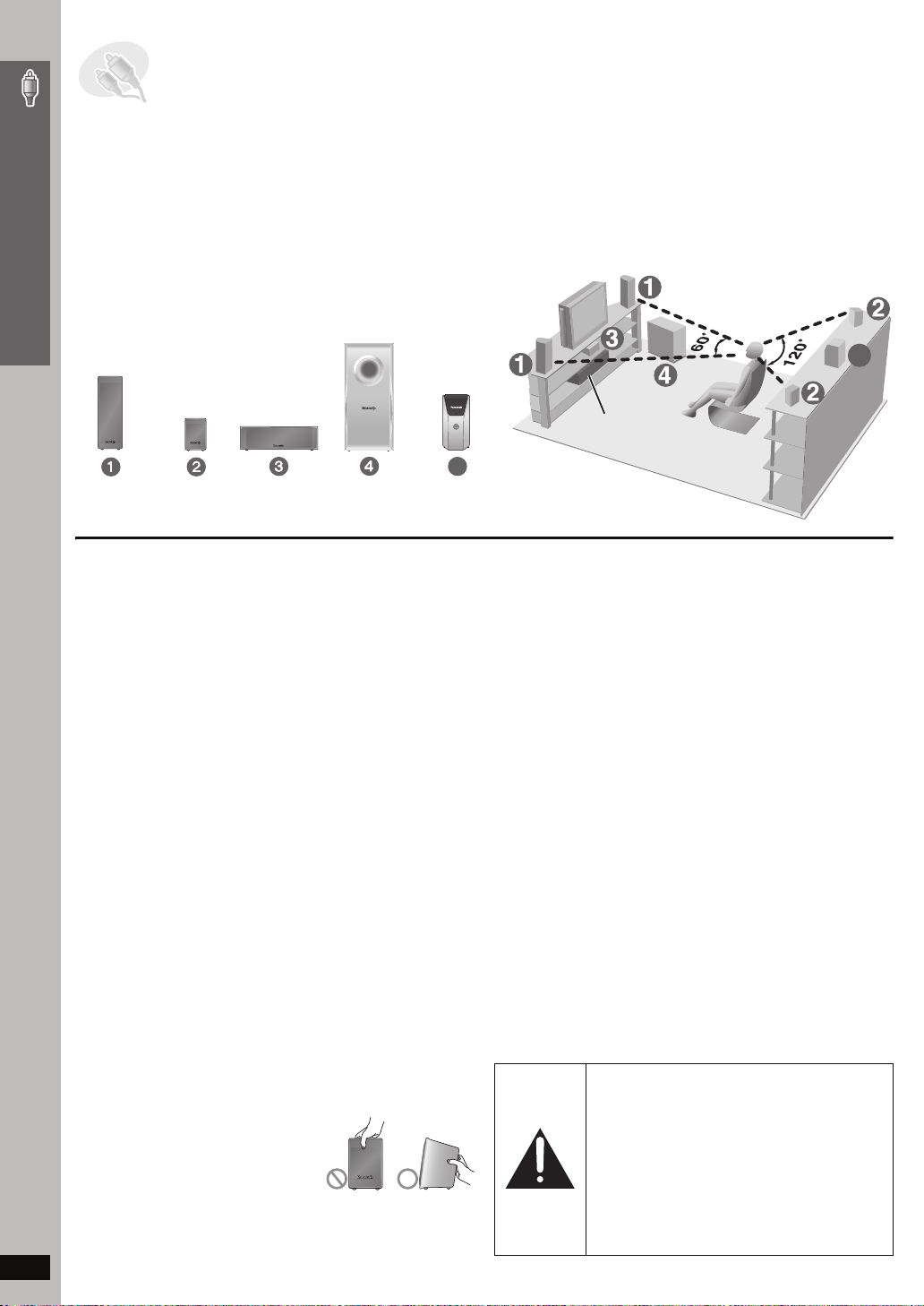
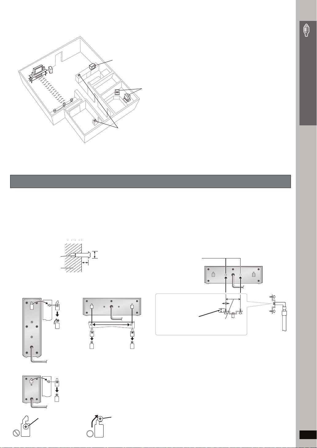
STEP1 Positioning the speakers
How you set up your speakers can affect the bass and the sound field. Note the following points:
≥ Place speakers on flat secure bases.
≥ Placing speakers too close to floors, walls, and corners can result in excessive bass. Cover walls and windows with thick cur tains.
≥ Left and right speakers are interchangeable, but front and surround speakers are not.
Setup example
Simple Setup
FRONT
(L, R)
SURROUND
(L, R)
CENTER SUBWOOFER WIRELESS
Place the front, center, and surround speakers at approximately the same
distance from the seating position.
The angles in the diagram are approximate.
Main unit
(with digital transceiver)
5
SYSTEM
5
≥Use only supplied speakers
Positioning the speakers
Using other speakers can damage the unit, and sound quality will be
negatively affected.
≥ Set the speakers up on an even surface to prevent them from falling.
Take proper precautions to prevent the speakers from falling if you
cannot set them up on an even surface.
Main unit
[Note]
≥ Keep your speakers at least 10 mm (13/32q) away from the system for
proper ventilation.
≥ To allow for proper ventilation and to maintain good airflow around the
main unit, position it with at least 5 cm (2q) of space on all sides.
≥ Do not block the ventilation holes of the main unit.
Notes on speaker use
≥ You can damage your speakers and shorten their useful life if you play
sound at high levels over extended periods.
≥ Reduce the volume in the following cases to avoid damage:
– When playing distorted sound.
– When the speakers are reverberating due to a record player, noise
from FM broadcasts, or continuous signals from an oscillator, test
disc, or electronic instrument.
– When adjusting the sound quality.
– When turning the unit on or off.
Center speaker
≥ Vibration caused by the center speaker can disrupt the picture if it is
placed directly on the television. Put the center speaker on a rack or
shelf.
≥ To prevent the speakers from falling, do not place directly on top of the
television.
Wireless system
≥
Place the wireless system within approximately 10 m (33 ft) from the
main unit.
≥ Do not use the wireless system or the digital transceiver in a metal
cabinet or bookshelf.
Subwoofer
Place to the right or left of the television, on the floor or a sturdy shelf so
that it will not cause vibration. Leave about 30 cm (11
television.
13
/16q) from the
Caution
Do not touch the netted area of the
speakers.
RQT8779
e.g. Surround speaker
If irregular coloring occurs on your television
The front and center speakers are designed to be used close to a
television, but the picture may be affected with some televisions and
setup combinations.
If this occurs, turn the television off for about 30 minutes.
The demagnetizing function of the television should correct the problem.
If it persists, move the speakers further away from the television.
Caution
≥ The main unit and supplied speakers are to be
used only as indicated in this setup. Failure to
do so may lead to damage to the amplifier and/
or the speakers, and may result in the risk of
fire. Consult a qualified service person if
damage has occurred or if you experience a
sudden change in performance.
≥ Do not attempt to attach these speakers to
walls using methods other than those
described in this manual.
4
∫ Avoiding interference
To avoid possible interference, do not place the wireless system near any of the following devices.
The wireless system uses the same radio frequencies as other devices that may be present in your home.
e.g.
2.4GHz-band microwave oven
personal computer with
2.4GHz-band wireless LAN
2.4GHz-band cordless phone
The wireless system will automatically seek a clear channel if any of these other devices interfere with its communication. When this happens, the
wireless link indicator (“ [W] ”) flashes on the main unit, and there is a brief interruption in audio coming from the surround speakers.
This is the normal operation of the product working to assure the best possible performance of your Home Theater System.
If the interference persists, try moving the other devices to another location outside the range of the wireless system.
Speaker installation options
Simple Setup
∫ Attaching to a wall
You can attach all of the speakers to a wall.
≥
The wall or pillar on which the speakers are to be attached should be
capable of supporting 10 k
building contractor when attaching the speakers to a wall. Improper
attachment may result in damage to the wall and speakers.
1 Drive a screw (not included) into the wall.
‰4.0 mm (
2 Fit the speaker securely onto the screw(s) with the hole(s).
Front speaker
Surround speaker
5
/32q)
Wall or pillar
g
(22 lbs) per screw. Consult a qualified
‰7.5 t o 9.5 mm
19
/64q to 3/8q)
(
200 mm
7
/8q)
(7
3
/16q to 9/32q)
5.0 to 7.0 mm (
Center speaker
∫ Fitting speaker stands (not included)
Ensure the stands meet these conditions before purchasing them.
Note the diameter and length of the screws and the distance
between screws as shown in the diagram.
≥ The stands must be able to support over 10 kg (22 lbs).
≥ The stands must be stable even if the speakers are in a high
position.
e.g. Center speaker
Metal screw holes
For attaching to
speaker stands
3
/16q), pitch 0.8 mm (1/32q)
5mm (
Plate thickness plus
7 mm to 10 mm
9
(plus
/32q to 13/32q)
60 mm (2
3
/8q)
Speaker stand
(not included)
Positioning the speakers
e.g.
In this position, the
speaker will likely
fall if moved to the
left or right.
Move the speaker
so that the screw
is in this position.
RQT8779
5
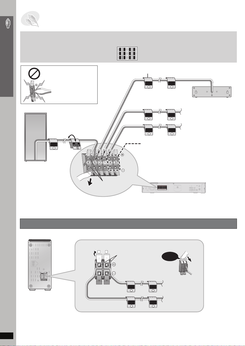
STEP2 Speaker connections
Simple Setup
Be careful not to cross
(short-circuit) or reverse
the polarity of the speaker
wires as doing so may
damage the speakers.
2 Sheets of speaker cable stickers
≥ Attach the speaker-cable stickers to
make connection easier.
CENTER
WOOFER
SUB
6
5
5
6
SUB
WOOFER
CENTER
SURROUND
SURROUND
Rch
Lch
3
4
4
3
Rch
SURROUND
SURROUND
FRONT
FRONT
Rch
Lch
2
1
1
2
Lch Lch
Rch
FRONT
FRONT
Speaker cable sticker
CENTER
5
CENTER
5
5 CENTER
Speaker connections
6 SUBWOOFER
FRONT
Rch
2
FRONT
Lch
1
SUB
WOOFER
6
Connect the surround speaker cables here only if you
do not intend to use the wireless system (➜ below).
≥ Do not attempt to connect more than one pair of
surround speakers to your home theater system.
Insert the wire fully.
Push!
i: White
j: Blue
Connecting the surround speaker cables to the wireless system
Wireless system
FRONT
Rch
2
FRONT
Lch
1
Main unit
2 FRONT (R)
1 FRONT (L)
R
L
Insert the wire fully.
i: White
Click!
j: Blue
Rch
4
Lch
3
4 SURROUND (R)
3 SURROUND (L)
RQT8779
SURROUND
Rch
4
SURROUND
Lch
3
SURROUND
SURROUND
6
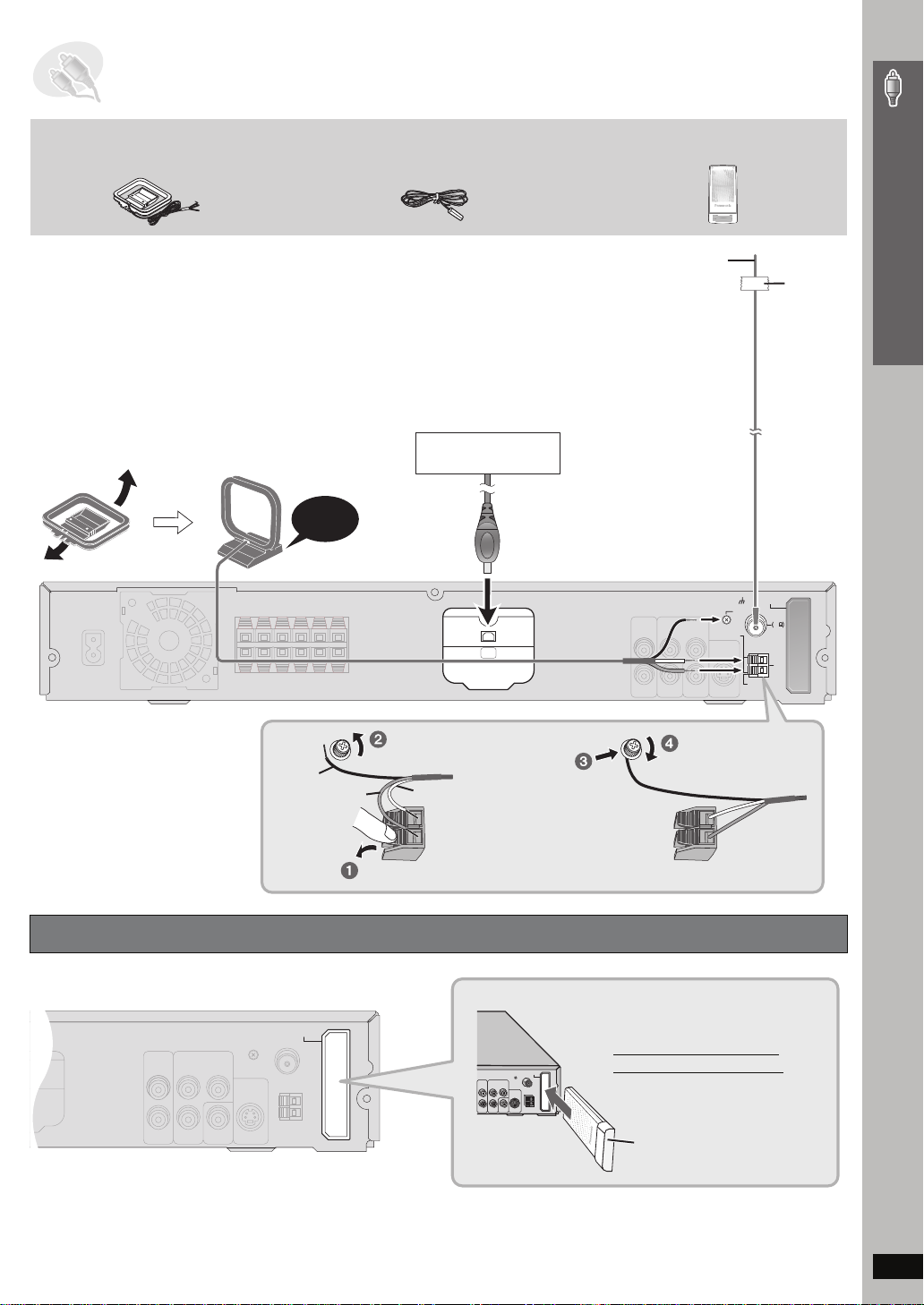
STEP3 Radio and digital transceiver connections
75
AM loop antenna FM indoor antenna Digital transceiver
Simple Setup
≥ Using an outdoor antenna (optional) (➜ page 27).
AM loop antenna
Stand the antenna up on its base.
Place the antenna where reception is best.
Keep loose antenna cable away from other
wires and cables.
Click!
Black
FM indoor antenna
Affix this end of the
antenna where
reception is best.
XM Connect & Play or XMPassport system (not included)
To prevent interference with wireless equipment, place the
antenna away from this unit, Panasonic wireless sound system
SH-FX80, Panasonic wireless system SH-FX50/SH-FX60, and
other equipment that emits radio waves (such as radio equipment
and microwave ovens).
Refer to page 28 for optimizing the reception.
XM Connect & Play or
XMPassport system
XM
Loosen the terminal screw with
a Phillips-head screwdriver.
Red
White
Adhesive
tape
Main unit
DIGITAL
TRANSCEIVER
LOOP
ANT GND
FM ANT
75
LOOP
AM
ANT
EXT
Re-tighten the terminal
screw.
Radio and digital transceiver connections
Connecting the digital transceiver
Main unit
DIGITAL
TRANSCEIVER
While pushing, insert the wire fully.
DIGITAL
TRANSMITTER
Insert the digital transceiver
into the slot.
Do not insert or remove
while the main unit is on.
Digital transceiver
Insert fully until you hear a click.
RQT8779
7
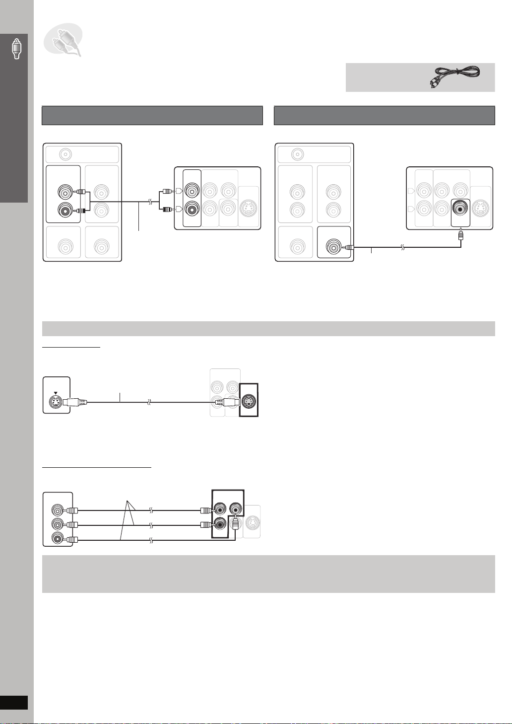
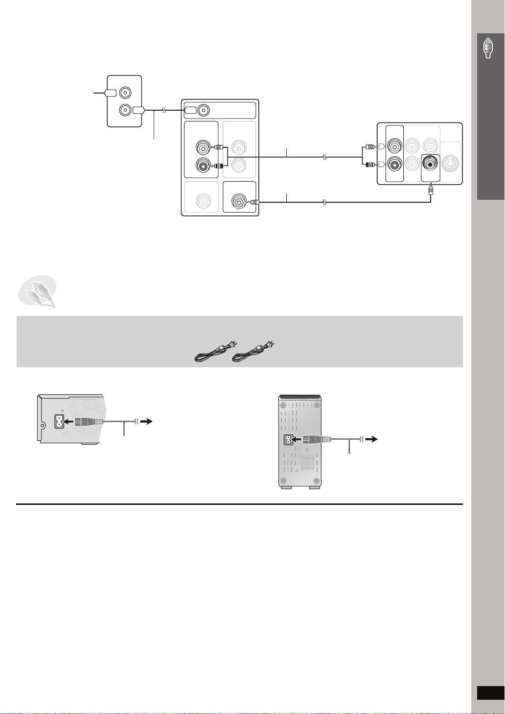
STEP4 Audio and video connections
AUX
≥ Do not connect through the video cassette recorder.
Due to copy guard protection, the picture may not be displayed properly.
≥ Turn the television off before connecting, and refer to the television’s operating instructions.
Simple Setup
Basic audio connection
Television (not included)
AUDIO
OUT
L
R
VIDEO OUT
RF IN
AUDIO
IN
VIDEO IN
Audio cable
Back of the main unit
AUX
COMPONENT VIDEO OUT
P
L
R
B
P
R
VIDEO
OUT
Y
S-VIDEO
OUT
(not included)
≥ This audio connection will enable you to play audio from your
television through your home theater system. Refer to “Operating other
equipment” (➜ page 31).
Audio and video connections
Other video connections for improved picture quality
S-VIDEO OUT
Television
(not included)
S-VIDEO
IN
S-video cable
(not included)
Back of the
main unit
COMPONENT VIDEO OUT
P
B
Y
P
R
VIDEO
OUT
S-VIDEO
OUT
Video cable
Basic video connection
Tel evis ion (not included)
RF IN
AUDIO
OUT
AUDIO
IN
L
R
VIDEO OUT
≥ Refer also to “Other video connections for improved picture quality”
(➜ below).
≥Using the S-VIDEO OUT terminal
The S-VIDEO OUT terminal achieves a more vivid picture than the
VIDEO OUT terminal by separating the chrominance (C) and luminance
(Y) signals. (Actual results depend on the television.)
VIDEO IN
Video cable (included)
Back of the main unit
AUX
COMPONENT VIDEO OUT
P
L
R
B
P
R
VIDEO
OUT
Y
S-VIDEO
OUT
COMPONENT VIDEO OUT
Tel evis ion
(not included)
COMPONENT
VIDEO IN
PB
PR
Y
Video cables
(not included)
Back of the
main unit
COMPONENT VIDEO OUT
P
B
Y
P
R
VIDEO
OUT
≥
Using the
COMPONENT VIDEO OUT
terminals
The COMPONENT VIDEO OUT terminals provides a purer picture than
the S-VIDEO OUT terminal. These terminals can be used for either
interlaced or progressive output. Connection using these terminals
outputs the color difference signals (P
separately in order to achieve high fidelity in reproducing colors.
S-VIDEO
OUT
≥ The description of the component video input terminals depends on
the television or monitor (e.g. Y/P
to terminals of the same color.
≥ After making this connection, select “Darker” from the “Black Level
B/PR) and luminance signal (Y)
B/PR, Y/B-Y/R-Y, Y/CB/CR). Connect
Control” in the “Video” tab (➜ page 24).
To enjoy progressive video
≥ Connect to a progressive output compatible television.
≥ Set “Video Output Mode” to “480p”, and then follow the instructions on the menu screen (➜ page 21, Picture Menu).
≥ All Panasonic televisions that have 480p input connectors are compatible. Consult the manufacturer if you have another brand of television.
RQT8779
8
∫ Cable TV box or video cassette recorder connection
AUX
AC IN
Cable TV box
or video cassette recorder
(not included)
To your cable TV service
or television antenna
RF IN
RF OUT
RF cable
(not included)
Tel evis ion (not included)
RF IN
AUDIO
OUT
AUDIO
IN
L
R
VIDEO OUT
VIDEO IN
STEP5 AC cord connections
Audio cable
(not included)
Video cable
(included)
Back of the main unit
AUX
L
R
COMPONENT VIDEO OUT
P
Y
P
B
R
VIDEO
OUT
S-VIDEO
OUT
Simple Setup
2 AC power supply cords
Main unit Wireless system
To household AC outlet
(AC 120 V, 60 Hz)
AC power supply cord
AC IN~
Conserving power
The main unit and the wireless system consume a small amount of
power when they are in standby mode [main unit: approx. 0.5 W,
wireless system: 0.5 W (in transmit mode), 1.2 W (in receive mode)]. To
save power when they are not to be used for a long time, unplug them
[Note]
The included AC power supply cords are for use with the main unit and
wireless system only. Do not use them with other equipment. Also, do
not use cords for other equipment with the main unit or wireless system.
from the household AC outlet.
You will need to reset some memory items after plugging in the main unit.
Audio and video connections / AC cord connections
To household AC outlet
(AC 120 V, 60 Hz)
AC power supply cord
RQT8779
9
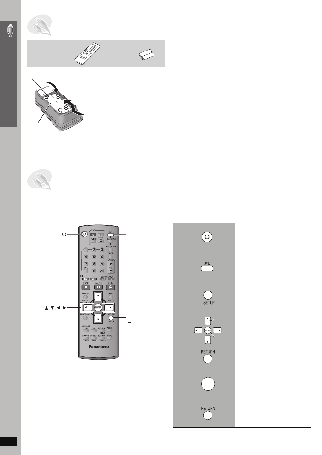
STEP6 Preparing the remote control
Remote control Batteries
Insert so the poles (i and j) match those in the remote control.
2
Simple Setup
3
≥ Do not use rechargeable type
1
R6/LR6, AA
batteries.
Do not:
≥ mix old and new batteries.
≥ use different types at the same time.
≥ heat or expose to flame.
≥ take apart or shor t circuit.
≥ attempt to recharge alkaline or manganese batteries.
≥ use batteries if the covering has been peeled off.
Mishandling of batteries can cause electrolyte leakage which can
severely damage the remote control.
Remove the batteries if the remote control is not going to be used for a
long period of time. Store in a cool, dark place.
∫ Use
Aim at the display (➜ page 11), avoiding obstacles, at a maximum
range of 7 m (23 feet) directly in front of the unit.
STEP7 Performing QUICK SETUP
The QUICK SETUP screen assists you to make necessary settings.
To display the picture from the main unit, turn on your television and change its video input mode (e.g. VIDEO 1, AV 1, etc.).
≥ To change your television’s video input mode, refer to its operating instructions.
≥ This remote control can perform some basic television operations (➜ page 31).
Preparing the remote control / Performing QUICK SETUP
ENTER
DVD
RETURN,
SETUP
1
2
3
Turn on the unit.
Select “DVD/CD”.
Press and hold to show
the QUICK SETUP
screen.
4
Select
Follow the messages
and make the settings.
Register
5
ENTER
6
Press to finish QUICK
SETUP.
Press repeatedly to exit.
10
RQT8779
To change these settings later
Select “QUICK SETUP” in the “Others” tab (➜ page 24).
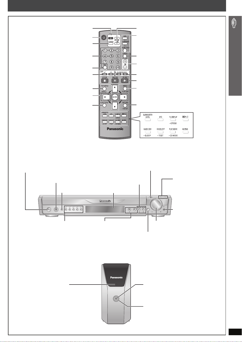
Control reference guide
See page references in parentheses.
Television operations (31)
Turn the unit on/off (10)
Change the television’s video input mode (31)
Select disc’s title numbers etc./Enter numbers (15)
Select the disc or show disc information (16)
Select preset radio stations/channels (26, 29)
Show a disc top menu (18) or program list (19)
Frame-by-frame/ Select or register menu items on the
television screen (15) /Browse XM radio categories (29)
Show on-screen menu (20)
Standby/on switch [POWER Í/I]
Press to switch the unit from on to standby mode
or vice versa. In standby mode, the unit is still
consuming a small amount of power. (14)
MUSIC PORT
Connect an external device (32)
SURROUND MUSIC
Equalizing the sound (14)
POWER
MUSIC
SURROUND
PORT
12345
MUSIC
5
DISC
SELECTOR
Adjust the television volume (31)
Select the source
DVD: DVD/CD (10)
TUNER/BAND: FM/AM (26), XM (28)
MUSIC P./AUX: FRONT MUSIC P./REAR MUSIC P.
Cancel (15)
Adjust the volume of the main unit (15)
Select radio stations/channels manually (26, 29)
Basic operations for play (14, 15)
Show a disc menu (18) or play list (19)
Return to previous screen (15)
or show the setup menu (23)
(16, 32)
To use functions labeled with “
Press and hold the button for at least 2 seconds.
4, 5 / X TUNING W
Skip or slow-search play (14)/
Select radio stations/channels (26, 29)
Display
TUNINGTUNING
MEMORYMEMORY
TUNE MODETUNE MODE
FM MODEFM MODE
AUX (31)
(30) (30)
(31)
(15, 28, 30)
(16, 17, 28)
(30)
(32)
< OPEN/CLOSE
Open/Close the disc drawer (14)
DISC EXCHANGE
Open the disc drawer to
exchange the disc in the play
position (14)
OPEN/CLOSE
DISC DISC
EXCHANGE SKIP
VOLUME
SELECTOR
DISC SKIP
Skip to the next disc tray (14)
Phones
Connect headphones (32)
§
(32),
-
”:
Control reference guide
5 DISC SELECTOR
Select the disc tray (14)
AC supply indicator [AC IN]
This indicator lights when the unit is
connected to the AC mains supply.
The unit is in the standby condition when the
AC power supply cord is connected.
The primary circuit is always “live” as long as
the power cord is connected to an electrical
outlet.
§
Refer to page 32, Using the Music Port.
∫ /
-
TUNE MODE / -FM MODE
Stop playing (14)/
Select the tuning mode (26, 28)
Adjust the FM reception condition (26)
1 / MEMORY
Play discs (14)/Memorize the receiving
radio stations/channels (26, 29)
AC IN
MUSIC PORT
VOL UME
Turn up/down the volume (14)
SELECTOR (26)
DVD/CD#FM#AM#XM#AUX#FRONT MUSIC P.#
REAR MUSIC P.
§
#Return to DVD/CD
MUSIC PORT
Connect an external device (32)
Lighting Ring
Lights when the wireless link is active.
RQT8779
11
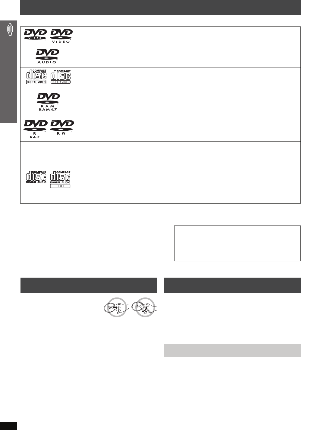
Discs that can be played
Operations in these instr uctions are described mainly with formats. Icons such as [DVD-V] show the formats.
DVD-Video [DVD-V]
—
DVD-Audio [DVD-A] [DVD-V]
≥ [DVD-V] Some DVD-Audio discs contain DVD-Video content. To play DVD-Video content, select “Play as DVD-Video” in
Other Menu (➜ page 22).
Video CD [VCD]
≥ Including SVCD (Conforming to IEC62107)
DVD-RAM [DVD-VR] [JPEG]
≥ [DVD-VR] Recorded with devices using Version 1.1 of the Video Recording Format (a unified video recording standard),
such as DVD video recorders, DVD video cameras, personal computers, etc.
≥ [JPEG] Recorded with Panasonic SD multi cameras or DVD video recorders using the DCF (Design rule for Camera
File system) Standard Version 1.0.
DVD-R (DVD-Video)/ DVD-RW (DVD-Video) [DVD-V]
≥ Discs recorded and finalized
§
on DVD video recorders or DVD video cameras.
—
§
A process that allows play on compatible equipment.
≥ It may not be possible to play all the above-mentioned discs in some cases due to the type of disc or condition of the recording.
∫ Discs that cannot be played
DVD-RW version 1.0, DVD-ROM, CD-ROM, CDV, CD-G, SACD,
DivX Video Discs and Photo CD, DVD-RAM that cannot be removed
from their cartridge, 2.6-GB and 5.2-GB DVD-RAM, and “Chaoji
VCD” available on the market including CVD, DVCD and SVCD that
do not conform to IEC62107.
iR (Video)/ iRW (Video) [DVD-V]
≥ Discs recorded and finalized
CD [CD] [WMA] [MP3] [JPEG] [VCD]
≥ This unit can play CD-R/RW recorded with the above formats. Close the sessions or finalize
≥ [CD] This unit is compatible with HDCD, but does not support the Peak Extend function (a function which expands the
dynamic range of high-level signals).
HDCD-encoded CDs sound better because they are encoded with 20 bits, as compared with 16 bits for all other CDs.
≥ [WMA] [MP3] [JPEG] This unit also plays HighMAT discs.
≥ [WMA] This unit does not support Multiple Bit Rate (MBR: an encoding process for audio content that produces an
audio file encoded at several different bit rates).
§
on DVD video recorders or DVD video cameras.
Note about using a DualDisc
≥ The digital audio content side of a DualDisc does not meet the
technical specifications of the Compact Disc Digital Audio
(CD-DA) format so playback may not be possible.
≥ Do not use a DualDisc in this unit as it may not be possible to
insert it correctly and it may get scratched or scraped.
Discs that can be played / Disc caution / Maintenance
Disc caution Maintenance
∫ To clean discs
Wipe with a damp cloth and
then wipe dry.
∫ Disc handling precautions
≥ Do not attach labels or stickers to discs. This may cause disc
warping, render ing it unusable.
≥ Do not write on the label side with a ball-point pen or other writing
instrument.
≥ Do not use record cleaning sprays, benzine, thinner, liquids which
prevent static electricity, or any other solvent.
≥ Do not use scratch-proof protectors or covers.
≥ Do not use the following discs:
– Discs with exposed adhesive from removed stickers or labels
(rented discs, etc).
– Discs that are badly warped or cracked.
– Irregularly shaped discs, such as heart shapes.
Clean this unit with a soft, dry cloth.
≥ Never use alcohol, paint thinner or benzine to clean this unit.
≥ Before using chemically treated cloth, carefully read the instructions that
came with the cloth.
Do not use commercially available lens cleaners as they may cause
malfunction. Cleaning of the lens is generally not necessary although
this depends on the operating environment.
Before moving the unit, ensure the disc trays are empty. Failure to
do so will risk severely damaging the discs and the unit.
§
the disc after recording.
12
RQT8779
 Loading...