

Operating Instructions
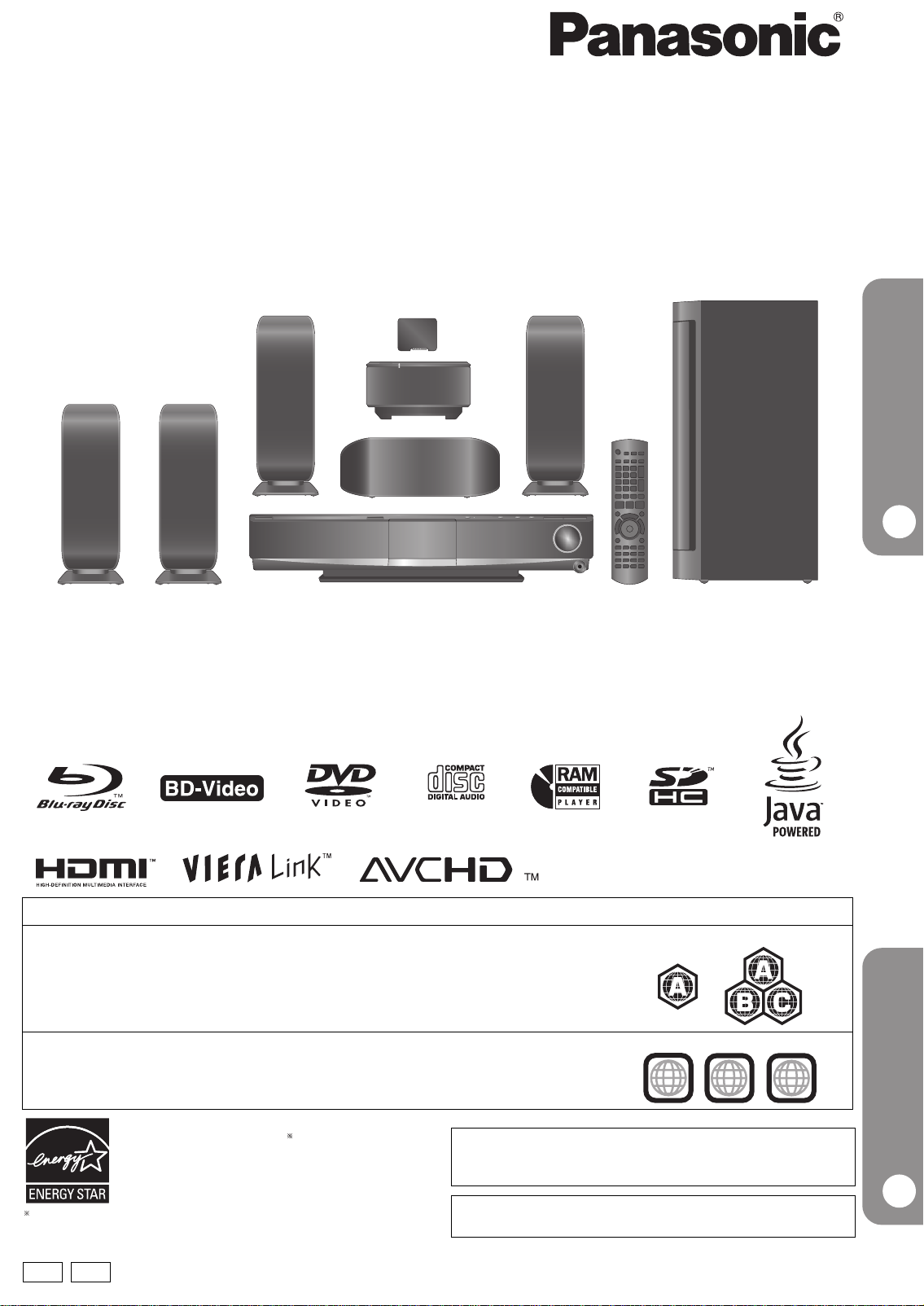
Blu-ray Disc Home Theater Sound System
Model No. SC-BT100
Quick Start Guide
P4
Dear customer
Thank you for purchasing this product.
For optimum performance and safety, please read these instructions carefully.
Before connecting, operating or adjusting this product, please read the instructions completely. Please keep this manual for future reference.
Region management information
BD-Video
This unit plays BD-Video marked with labels containing the region code A.
DVD-Video
This unit plays DVD-Video marked with labels containing the region number “1” or “ALL”.
Example:
Example:
1
ALL
1
2
4
As an ENERGY STAR Partner,
Panasonic has determined that
this product meets the ENERGY STAR
guidelines for energy efficiency.
For Canada only: The word “Participant” is used in place of the word
“Partner”.
®
®
P PC
If you have any questions contact
[[U.S.A.]:1-800-211-PANA(7262)
[Canada]:1-800-561-5505
The warranty can be found on page 46.
[[U.S.A.]:
[Canada]:The warranty can be found on page 47.
Enjoying surround sound
P27
RQT9129-P
Operations in these instructions are described mainly with the
remote control, but you can perform the operations on the main
unit if the controls are the same.
System SC-BT100
Main unit SA-BT100
Front speakers SB-HF100
Center speaker SB-HC100
Surround speakers SB-HS100
Subwoofer SB-HW560
Digital transmitter SH-FX67T
Wireless system SE-FX67
Accessory information
Please check and identify the supplied accessories. Use numbers indicated in parentheses when asking for replacement parts.
(Product numbers correct as of February 2008. These may be subject to change.)
Only for U.S.A.: To order accessories, refer to “Accessory Purchases” on page 46.
Only for Canada: To order accessories, call the dealer from whom you have made your purchase.
∏∏ ∏∏
1 Remote control
(N2QAKB000061)
2 Remote control batteries 1 AM loop antenna
(N1DAAAA00002)
1 FM indoor antenna
(RSA0007-M)
∏∏ ∏∏
1 Video cable
(K2KA2BA00001)
1 Sheet of speaker
cable stickers
5 Speaker cables
[REEX0859-L (White)]
[REEX0867A-L (Red)]
[REEX0858-L (Green)]
[REEX0860A-L (Blue)]
[REEX0868A-L (Gray)]
2 AC power supply cords
(K2CB2CB00021)
≥For use with this unit only. Do not use
them with other equipment. Also, do not
use cords for other equipment with this
unit or wireless system.
The enclosed Canadian French label sheet corresponds to the English display on the front and back side of the unit.
WARNING:
TO REDUCE THE RISK OF FIRE, ELECTRIC SHOCK OR
PRODUCT DAMAGE,
≥DO NOT EXPOSE THIS APPARATUS TO RAIN, MOISTURE,
DRIPPING OR SPLASHING AND THAT NO OBJECTS FILLED
WITH LIQUIDS, SUCH AS VASES, SHALL BE PLACED ON THE
APPARATUS.
≥USE ONLY THE RECOMMENDED ACCESSORIES.
≥DO NOT REMOVE THE COVER (OR BACK); THERE ARE NO
USER SERVICEABLE PARTS INSIDE. REFER SERVICING TO
QUALIFIED SERVICE PERSONNEL.
CAUTION!
THIS PRODUCT UTILIZES A LASER.
USE OF CONTROLS OR ADJUSTMENTS OR PERFORMANCE
OF PROCEDURES OTHER THAN THOSE SPECIFIED HEREIN
MAY RESULT IN HAZARDOUS RADIATION EXPOSURE.
DO NOT OPEN COVERS AND DO NOT REPAIR YOURSELF.
REFER SERVICING TO QUALIFIED PERSONNEL.
(For wireless system)
The following mark and symbols are located on bottom of the unit.
CAUTION
RISK OF ELECTRIC SHOCK
DO NOT OPEN
CAUTION: TO REDUCE THE RISK OF ELECTRIC
2
SHOCK, DO NOT REMOVE SCREWS.
NO USER-SERVICEABLE PARTS
INSIDE.
REFER SERVICING TO QUALIFIED
SERVICE PERSONNEL.
The lightning flash with arrowhead symbol, within
an equilateral triangle, is intended to alert the user
to the presence of uninsulated “dangerous
voltage” within the product’s enclosure that may be
of sufficient magnitude to constitute a risk of
electric shock to persons.
The exclamation point within an equilateral triangle
is intended to alert the user to the presence of
important operating and maintenance (servicing)
instructions in the literature accompanying the
appliance.
THE FOLLOWING APPLIES ONLY IN THE U.S.A.
FCC Note:
This equipment has been tested and found to comply with the limits for a Class
B digital device, pursuant to Part 15 of the FCC Rules.
These limits are designed to provide reasonable protection against harmful
interference in a residential installation. This equipment generates, uses and
can radiate radio frequency energy and, if not installed and used in accordance
with the instructions, may cause harmful interference to radio communications.
However, there is no guarantee that interference will not occur in a particular
installation. If this equipment does cause harmful interference to radio or
television reception, which can be determined by turning the equipment off and
on, the user is encouraged to try to correct the interference by one or more of
the following measures:
≥ Reorient or relocate the receiving antenna.
≥ Increase the separation between the equipment and receiver.
≥ Connect the equipment into an outlet on a circuit different from that to which
the receiver is connected.
≥ Consult the dealer or an experienced radio/TV technician for help.
FCC caution: To maintain compliance with FCC regulations, shielded interface
cables must be used with this equipment. Operation with non-approved
equipment or unshielded cables may result in interference to radio and TV
reception. Any changes or modifications not approved by the party responsible
for compliance could void the user’s authority to operate this equipment.
This device complies with Part 15 of the FCC Rules.
Operation is subject to the following two conditions:
(1) This device may not cause harmful interference, and
(2) this device must accept any interference received, including interference
that may cause undesired operation.
Responsible Party:
Panasonic Corporation of North America
One Panasonic Way
Secaucus, NJ 07094
Support Contact:
Panasonic Consumer Electronics Company
Telephone No.: 1-800-211-PANA (7262)
WARNING:
To satisfy FCC RF exposure requirements for mobile transmitting devices, a
separation distance of 20 cm or more should be maintained between the
antenna of this device and persons during device operation. To ensure
compliance, operations at closer than this distance is not recommended. The
antenna used for this transmitter must not be co-located in conjunction with any
other antenna or transmitter.
THE FOLLOWING APPLIES ONLY IN CANADA.
(For wireless system)
This Class B digital apparatus complies with Canadian ICES-003.
This device complies with RSS-210 of the IC Rules.
Operation is subject to the following two conditions:
(1) This device may not cause harmful interference,
(2) This device must accept any interference received, including interference
that may cause undesired operation of the device.
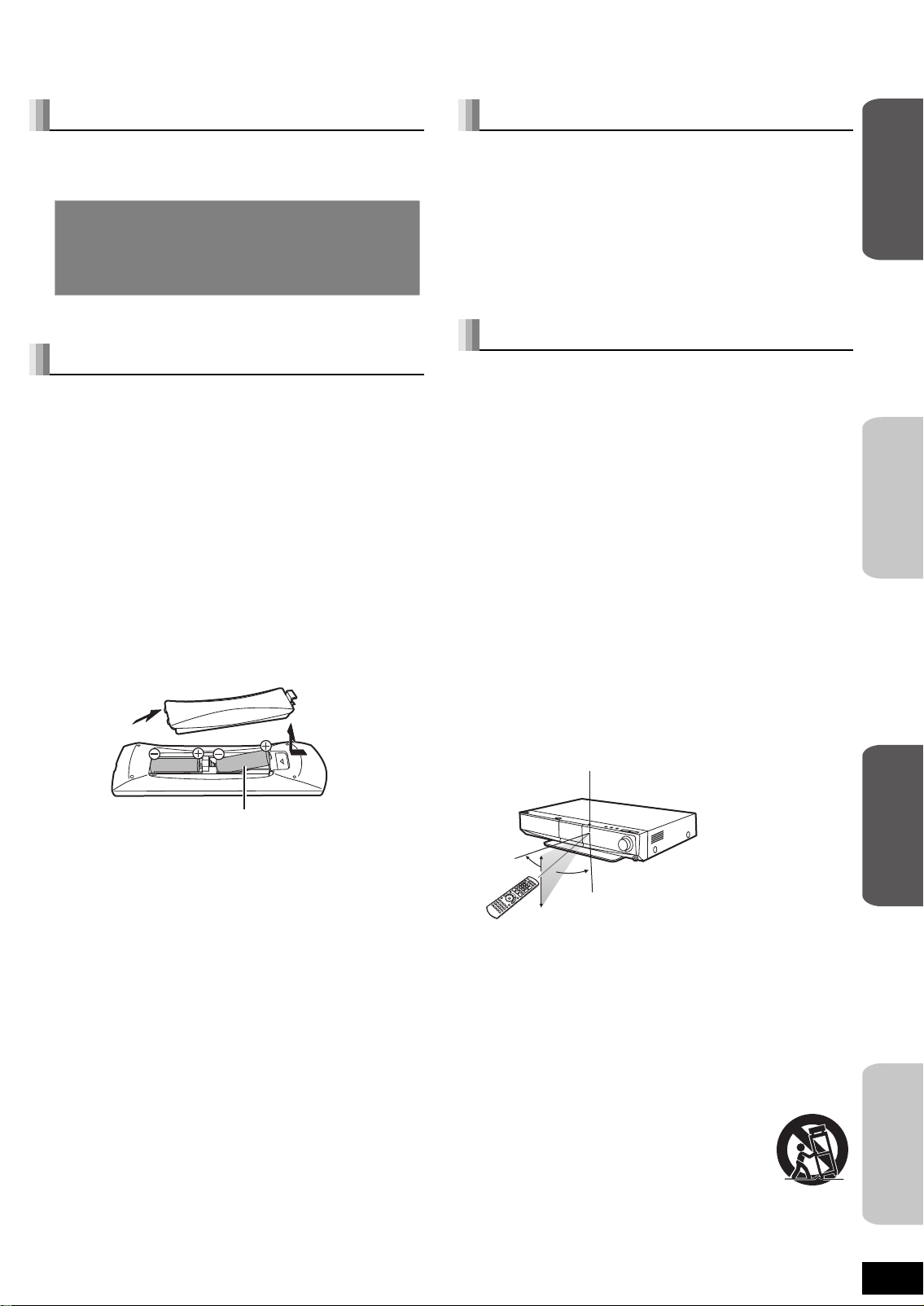
Table of contents
Getting started
Accessory information ..................................... 2
Preparing the remote control........................... 3
IMPORTANT SAFETY INSTRUCTIONS............ 3
Quick Start Guide
STEP 1 Positioning ....................................4
STEP 2 Basic connections........................6
STEP 3 Setting up the unit ........................9
Control reference guide.................................. 10
Disc and card information.............................. 12
Basic operations
Basic play (Playing video contents).............. 14
Enjoying TV with this unit’s speakers........... 17
Enjoying the FM/AM radio .............................. 18
Playing music.................................................. 19
Playing an iPod on this unit........................... 20
Advanced operations
Playing still pictures ....................................... 22
Different kinds of playback for BD-Video ..... 24
Showing FUNCTIONS menu........................... 25
Changing audio quality/sound field .............. 26
Enjoying surround sound .............................. 27
Linked operations with the TV
(VIERA Link
Changing settings with the on-screen menu
TM
“HDAVI ControlTM”)............... 28
... 30
Changing settings with the setup menu ....... 32
Reference
Optional connections and settings ............... 35
Frequently asked questions........................... 37
Messages ......................................................... 38
Troubleshooting guide ................................... 39
Disc and card handling................................... 42
Maintenance .................................................... 42
Glossary........................................................... 43
Specifications .................................................. 44
Limited Warranty (ONLY FOR U.S.A.) ........... 46
Limited Warranty (ONLY FOR CANADA) ...... 47
Product Service............................................... 47
Index.................................................. Back cover
Getting started
Basic
operations
Preparing the remote control
Batteries
Insert so the poles (i and j) match those in the remote control.
When closing the lid, insert it from the j (minus) side.
R6/LR6, AA
≥Do not use rechargeable type batteries.
≥Do not mix old and new batteries.
≥Do not use different types at the same time.
≥Do not heat or expose to flame.
≥Do not leave the battery(ies) in an automobile exposed to direct
sunlight for a long period of time with doors and windows closed.
≥Do not take apart or short circuit.
≥Do not attempt to recharge alkaline or manganese batteries.
≥Do not use batteries if the covering has been peeled off.
Mishandling of batteries can cause electrolyte leakage which can
damage items the fluid contacts and may cause a fire.
Remove batteries if the remote control is not going to be used for a
long period of time. Store in a cool, dark place.
Use
Remote control signal sensor
10˚
30˚
If you cannot operate the unit using the remote control after
changing the batteries, please re-enter the codes (> 42).
30˚
30˚
7 m (23 ft.) directly in front of the unit
IMPORTANT SAFETY INSTRUCTIONS
Read these operating instructions carefully before using the unit. Follow the safety instructions on the unit and the applicable safety instructions
listed below. Keep these operating instructions handy for future reference.
1) Read these instructions.
2) Keep these instructions.
3) Heed all warnings.
4) Follow all instructions.
5) Do not use this apparatus near water.
6) Clean only with dry cloth.
7) Do not block any ventilation openings. Install in accordance with
the manufacturer’s instructions.
8) Do not install near any heat sources such as radiators, heat
registers, stoves, or other apparatus (including amplifiers) that
produce heat.
9) Do not defeat the safety purpose of the polarized or
grounding-type plug. A polarized plug has two blades with one
wider than the other. A grounding-type plug has two blades and
a third grounding prong. The wide blade or the third prong are
provided for your safety. If the provided plug does not fit into your
outlet, consult an electrician for replacement of the obsolete
outlet.
10) Protect the power cord from being walked on or pinched
particularly at plugs, convenience receptacles, and the point
where they exit from the apparatus.
11) Only use attachments/accessories specified by the
manufacturer.
12) Use only with the cart, stand, tripod, bracket, or
table specified by the manufacturer, or sold with
the apparatus. When a cart is used, use caution
when moving the cart/apparatus combination to
avoid injury from tip-over.
13) Unplug this apparatus during lightning storms or
when unused for long periods of time.
14) Refer all servicing to qualified service personnel. Servicing is
required when the apparatus has been damaged in any way,
such as power-supply cord or plug is damaged, liquid has been
spilled or objects have fallen into the apparatus, the apparatus
has been exposed to rain or moisture, does not operate
normally, or has been dropped.
Advanced
RQT9129
3
operations
Reference

STEP 1 Positioning
Caution
≥The main unit and supplied speakers are to be used only as indicated in this setup. Failure to do so may lead to damage
to the amplifier and/or the speakers, and may result in the risk of fire. Consult a qualified service person if damage has
occurred or if you experience a sudden change in performance.
≥Do not attempt to attach these speakers to walls using methods other than those described in this manual.
How you set up your speakers can affect the bass and the sound field.
Note the following points:
≥Place speakers on flat secure bases.
≥Placing speakers too close to floors, walls, and corners can result in
excessive bass. Cover walls and windows with thick curtains.
Center speaker
Put on a rack or shelf. Vibration caused by
the speaker can disrupt the picture if it is
placed directly on the TV.
Main unit
Digital
transmitter
§
Left and right
speakers are
interchangeable
To allow for proper ventilation and to maintain
good airflow around the main unit, position it
with at least 5 cm (2q) of space on all sides.
[Note]
Keep your speakers at least 10 mm (
13
/32q) away from the system for
proper ventilation.
Setup example
Place the front, center, and surround speakers at approximately the
same distance from the seating position. The angles in the diagram
are approximate.
SubwooferFront speakers
60º
Place to the right or
left of the TV, on the
floor or a sturdy shelf
so that it will not cause
vibration. Leave about
30 cm (1113/16q) from the
TV.
Surround speakers
Left and right
speakers are
120º
interchangeable.
Wireless system
§
Place the wireless system within approximately
10 m (33 ft.) from the main unit.
§
Do not use the wireless system or the digital
transmitter in a metal cabinet or bookshelf.
Do not use a front speaker as a surround speaker or vice versa. Verify the type of speaker with the label on
the rear of the speaker.
NOTE
To avoid interference, maintain the following distances between the wireless system and other electronic
devices that use the same radio frequency (2.4 GHz band).
The wireless system will automatically seek a clear channel if any of these
other devices interfere with its communication. When this happens, the
wireless link indicator (“
[W2S] ” or “ [W4S] ”) flashes on the main unit, and
there is a brief interruption in audio coming from the surround speakers.
This is the normal operation of the product working to assure the best
possible performance of your home theater system.
If the interference persists, try moving the other devices to another location
outside the range of the wireless system or move the wireless system nearer to the main unit.
Wireless
system
Wireless LAN:
approx. 2 m (6
1
/2 ft.)
Cordless phone and other
electronic devices:
approx. 2 m (6
1
/2 ft.)
Enjoying 7.1-channel surround sound
Optional Panasonic wireless accessory SH-FX67/Optional Panasonic speaker system SB-HS100A
You can enjoy 7.1ch surround sound when you use the optional Panasonic wireless system SH-FX67 and speaker system
SB-HS100A. Refer to the relevant operating instructions for details.
≥You can also enjoy 7.1ch surround sound by connecting an amplifier using audio cable via the SURROUND and SURROUND
BACK terminals on the back of the main unit (> 36).
≥System speaker settings will need to be changed in order to enjoy 7.1ch surround sound (> 34).
4

∫ Notes on speaker use
≥Use only supplied speakers
Using other speakers can damage the unit, and sound quality will be
negatively affected.
≥You can damage your speakers and shorten their useful life if you
play sound at high levels over extended periods.
≥Reduce the volume in the following cases to avoid damage:
– When playing distorted sound.
– When the speakers are reverberating due to a record player, noise
from FM broadcasts, or continuous signals from an oscillator, test
disc, or electronic instrument.
– When adjusting the sound quality.
– When turning the unit on or off.
∫ If irregular coloring occurs on your TV
The front and center speakers are designed to be used close to a TV,
but the picture may be affected with some TVs and setup
combinations.
If this occurs, turn the TV off for about 30 minutes.
The demagnetizing function of the TV should correct the problem. If it
persists, move the speakers further away from the TV.
∫ Caution
Do not touch the front netted area of the speakers. Hold by the sides.
e.g., Center speaker
Do not
Do
Speaker installation options
Attaching to a wall
You can attach all of the speakers (except subwoofer) to a wall.
≥The wall or pillar on which the speakers are to be attached should
be capable of supporting 10 kg (22 lbs) per screw. Consult a
qualified building contractor when attaching the speakers to a wall.
Improper attachment may result in damage to the wall and
speakers.
1 Detach stand (Front/Surround speakers).
Remove the
3 screws
3 Fit the speaker securely onto the screw(s) with
the hole(s).
Front/Surround speaker
e.g.,
In this position, the
speaker will likely fall
if moved to the left or
Do not
right.
Center speaker
Move the speaker
so that the screw is
in this position.
Do
Fitting speaker stands (not included)
(Except subwoofer)
Ensure the stands meet these conditions before purchasing them.
Note the diameter and length of the screws and the distance between
screws as shown in the diagram.
≥The stands must be able to support over 10 kg (22 lbs).
≥The stands must be stable even if the speakers are in a high
position.
e.g., Center speaker
Metal screw holes
For attaching to
speaker stands
5.0 mm (
Plate thickness plus 7 mm to
10 mm
3
/16q), pitch 0.8 mm (1/32q)
(plus 9/32q to 13/32q)
60 mm (2
3
/8q)
Speaker stand
(not included)
Getting started
Quick Start Guide
2 Drive a screw (not included) into the wall.
At least 30 mm (1
‰4.0 mm (
Wall or pillar
≥Center/Front/Surround speaker
Ensure that the screw is positioned at least 70 mm (2
from the ceiling.
≥Center speaker
Ensure that the screw is positioned at least 100 mm (3
away from the wall.
Fixing the position for the center speaker screws.
1 Drive in a screw 50.5 mm (2q) left of
the right side of the center speaker
as seen directly from the front.
2 Drive another screw 160 mm
(6
5
/32q)
5
/16q) left of the first screw.
‰7.5 mm to 9.4 mm
19
/64q to 3/8q)
(
7.0 mm to 9.4 mm (
3
/16q)
9
/32q to 3/8q)
3
/4q) away
15
/16q)
Prevent the speakers from falling
e.g., Front speaker
String (not included)
Thread from the wall to the
speaker and tie tightly.
Screw eye
(not included)
Rear of the speaker
≥You will need to obtain the appropriate screw eyes to match the walls
and pillars to which they are going to be fastened.
≥Consult a qualified housing contractor concerning the appropriate
procedure when attaching to a concrete wall or a surface that may
not have strong enough support. Improper attachment may result in
damage to the wall or speakers.
Wall
Approx.
150 mm
29
/32z)
(5
RQT9129
5

STEP 2 Basic connections
≥Do not place the unit on amplifiers or equipment that may become hot. The heat can damage the unit.
≥Turn off all equipment before connection and read the appropriate operating instructions.
Speaker cables and transmitter connection
Sheet of speaker cable
stickers
Speaker cable for surround
speaker (R) (Grey)
Speaker cable for front
speaker (L) (White)
Speaker cable for center
speaker (Green)
Preparation
∫ Attach the speaker cable stickers to make connection
easier.
e.g., Center speaker
センター
CENTER
Speaker cable sticker
5
(included)
センター
CENTER
5
7 Digital transmitter
Insert fully until you
R
AUXP
hear a click.
ANT
AM
EXT
L
LOOP
LOOP
ANT
GND
R
FM ANT
75ǡ
Main unit
AC IN
SURROUND
BACK
SUBWOOFER
SPEAKERS
6
6
ǡ
CENTER
OPTICAL IN
DIGITAL
AV OUT
VIDEO OUT
Y
COMPONENT
PB
VIDEO OUT
SURROUND
OUT
2
1
5
6ǡ6
ǡ
R
L
FRONT
Speaker cable for front
speaker (R) (Red)
Speaker cable for surround
speaker (L) (Blue)
Digital transmitter
∫ Set the surround selector at the rear of the wireless
system to its center.
SPEAKERS
NCEINTES
LS / RB LB / RS
SURR
SURROUND (3 – 6 )
L
AMBIOPHONIQUES
SIDERSIDE
Wireless system
I/D SET
NIQUES
I/D SET
AC I
N
Do
DIGITAL
TRANSMITTER
Do not
SURRSURRSURR
Do not
SURR
L
SIDERSIDE
SPEAKERS
EN
CEINTES
LS / RB LB / RS
SURROUND (3 – 6 )
AMBIOPHO
AC I
N
GreenPurple
Red
White
Blue Grey
Connect to the terminals of the
same color.
Subwoofer
Speaker cables (included)
Surround
Front speaker (R) Front speaker (L)
Fron t
Fron t
speaker (L)
Center speaker
Center
≥Do not use a front speaker as a surround speaker or vice versa. Verify the type of speaker with the label on the rear of the
speaker.
≥Do not insert or remove the digital transmitter while the main unit is on.
NOTE
≥Insert the wires fully.
i: White
j: Blue
Push!
≥Be careful not to cross (short-circuit) or reverse the polarity of the speaker wires as doing so may damage the speakers.
Surround
speaker (R)
SurroundSurround
6
Do not

Connection to a TV
OPTICAL IN
L
R
DIGITAL
COMPONENT
VIDEO OUT
VIDEO OUT
Y
AUXP
R
PB
SURROUND
SURROUND
BACK
AV OUT
SPEAKERS
R
L
6ǡ6
ǡ
CENTER
6
ǡ
SUBWOOFER
FRONT
6
5
2
1
FM ANT
ANT
EXT
LOOP
AM
75ǡ
GND
ANT
LOOP
AC IN
OUT
OPTICAL IN
L
R
DIGITAL
COMPONENT
VIDEO OUT
VIDEO OUT
Y
AUXP
R
PB
AV OUT
L
FRONT
1
FM ANT
ANT
EXT
LOOP
AM
75ǡ
GND
ANT
LOOP
OPTICAL IN
L
R
DIGITAL
COMPONENT
VIDEO OUT
VIDEO OUT
Y
AUXP
R
PB
SURROUND
SURROUND
BACK
AV OUT
SPEAKERS
R
L
6ǡ6
ǡ
CENTER
6
ǡ
SUBWOOFER
FRONT
6
5
2
1
FM ANT
ANT
EXT
LOOP
AM
75ǡ
GND
ANT
LOOP
AC IN
OUT
OPTICAL IN
L
R
DIGITAL
COMPONENT
VIDEO OUT
VIDEO OUT
Y
AUXP
R
PB
AV OUT
L
FRONT
1
FM ANT
ANT
EXT
LOOP
AM
75ǡ
GND
ANT
LOOP
≥Do not connect through the video cassette recorder. Due to copy guard protection, the picture may not display properly.
With an HDMI cable
HDMI
compatible
TV
AV IN
AUDIO OUT
L
R
Audio cable
(not included)
≥The optical digital
audio cable can be
Main unit
HDMI cable (not included)
used when connecting
to televisions with
optical out terminals
(> right).
Please use High Speed HDMI cables that have the HDMI logo (as shown on the cover).
It is recommended that you use Panasonic’s HDMI cable.
Recommended part number:
NOTE
RP-CDHG10 (1.0 m/3.3 ft.), RP-CDHG15 (1.5 m/4.9 ft.), RP-CDHG20 (2.0 m/6.6 ft.),
RP-CDHG30 (3.0 m/9.8 ft.), RP-CDHG50 (5.0 m/16.4 ft.), etc.
NECESSARY SETTINGS
“HDMI Video Mode” : “On”/“HDMI Audio Output” : “Off” (> 33)
With this connection, you can use VIERA Link “HDAVI Control” (> 28).
§
These audio connections will enable you to play audio from your television through your home theater system (> 17).
OPTICAL
OUT
Getting started
§
Optical
digital audio
§
cable
(not included)
Quick Start Guide
With Video cable
Video cable
TV
Main unit
Optional connections
≥For those who want to enjoy higher picture quality and have a TV equipped with an HDMI terminal (> above)
NOTE
≥For those who want to enjoy higher picture quality and have a TV equipped with a COMPONENT VIDEO IN terminal (> 35)
≥For those who have a Set Top Box (Satellite receiver, Cable box, etc) or video cassette recorder (> 35)
§
These audio connections will enable you to play audio from your television through your home theater system (> 17).
VIDEO IN
AUDIO IN
AUDIO OUT
L
L
R
R
Video cable (included)
Audio cable
§
(not included)
≥The optical digital
audio cable can be
used when connecting
OPTICAL
OUT
Optical
digital audio
§
cable
(not included)
to televisions with
optical out terminals
(> right).
(Continued on the next page)
RQT9129
7

STEP 2 Basic connections
Radio antenna connections
AM loop antennaFM Indoor antenna
FM indoor antenna (included)
Affix this end of the antenna where
reception is best.
Main unit
AC IN
Adhesive tape
SURROUND
SURROUND
BACK
OUT
SPEAKERS
2
1
6
5
6ǡ6
6
ǡ
ǡ
R
L
FRONT
CENTER
SUBWOOFER
OPTICAL IN
DIGITAL
AV OUT
VIDEO OUT
Y
COMPONENT
≥Keep loose antenna cables away from other wires and cables.
Optional connections
≥Using FM/AM outdoor antenna (optional) (> 36).
NOTE
AC power supply cord connections
AC power supply cord
AM loop antenna (included)
Stand the antenna up on its base.
Place the antenna where reception
best.
is
Red
White
R
AUXP
ANT
AM
EXT
L
LOOP
LOOP
ANT
PB
VIDEO OUT
GND
R
FM ANT
75ǡ
Black
Push!
DIGITAL
TRANSMITTER
Click!
Main unit
AC IN
SURROUND
SURROUND
BACK
OUT
SPEAKERS
2
1
6
5
6ǡ6
6
ǡ
ǡ
R
L
FRONT
SUBWOOFER
CENTER
AC power supply cord
(included)
To a household AC outlet
(AC 120 V, 60 Hz)
OPTICAL IN
DIGITAL
AV OUT
VIDEO OUT
Y
COMPONENT
PB
VIDEO OUT
AUXPR
ANT
AM
EXT
L
LOOP
LOOP
ANT
GND
R
FM ANT
75ǡ
DIGITAL
TRANSMITTER
Wireless system
SPEAKERS
ENCEINTES
LS / RB LB / RS
I/D SET
SURR
SURROUND (3 – 6 )
L
AMBIOPHONIQUES
SIDERSIDE
AC power supply cord
(included)
To a household AC outlet
(AC 120 V, 60 Hz)
AC IN
Power consumption
The main unit and the wireless system consume a small amount of power when they are turned off (Main unit: approx. 0.3 W, wireless
system: approx. 0.2 W). To save power when they are not to be used for a long time, unplug them from the household AC outlet.
NOTE
You will need to reset some memory items after plugging in the main unit.
The included AC power supply cords are for use with the main unit and wireless system only. Do not use them with other equipment.
Also, do not use cords for other equipment with the main unit or wireless system.
≥When the AC power supply cord is connected for the first time, “PLEASE WAIT” is displayed on the main unit’s display for about
8
30 seconds and power is turned off automatically.

STEP 3 Setting up the unit
Turn on the main unit and wireless system
Turn on the power of the main unit and the wireless system after all connections are complete.
AUTO OPERATION ON/OFF
indicator
R
E
W
PO
AUTO
O
P
E
R
AT
IO
N
O
N
/O
F
F
Standby/on indicator (Í)
Preparation
Turn on the TV and select the appropriate video input on the TV.
1 Press [POWER C I, B Í] on the wireless
system.
≥AUTO OPERATION ON/OFF indicator lights red when the
wireless system is turned on and lights green when the wireless link is activated.
2 Press [POWER Í/I] on the main unit.
≥Standby/on indicator (Í) goes out when the unit is turned on.
≥When the link between the main unit and the wireless system is
activated, “[W2S]” or “[W4S]” is illuminated in the main unit’s display.
≥If “[W2S]” or “[W4S]” is flashing in the main unit’s display, check that the digital transmitter
at the back of the main unit is inserted correctly.
VIDEO1
e.g., “[W2S]”
W2S
Getting started
SLSD
Quick Start Guide
Easy Setting
When the system is switched on for the first time, a screen for the basic settings is displayed automatically. Follow the on-screen prompts to make
basic settings for the system.
1 Press [Í].
Setup screen appears.
[Í]
≥If this unit is connected to a Panasonic TV (VIERA) supporting HDAVI Control 2 or HDAVI
Control 3 via an HDMI cable, then the “On-screen Language” and “TV Aspect” setting
information on the TV are captured from the TV.
2 Follow the on-screen instructions and make the settings with
[3, 4] and [OK].
“On-screen Language” (> 33) and “TV Aspect” (> 33) are set.
≥You can perform this setup anytime by selecting “Easy Setting” in the Setup menu. (> 32)
≥You can also change these settings individually. (> 33)
[OK]
[3, 4]
Presetting the radio stations automatically
Up to 30 stations can be set in each band, FM and AM.
[FM/AM]
1 Press [FM/AM] to select “FM” or “AM”.
2 Press [6, 5]
AM: 520).
3 Press and hold [OK].
Release the button when “M” begins to flash.
[6, 5]
to select the lowest frequency (FM: 87.9 or 87.5,
W2S
W4S
DISC
iPod
SD
M
PLxHD
96/24
DD EX
NEO:6
+
[OK]
The tuner tunes to the lowest frequency and starts to preset all the stations it can receive
into the channels in ascending order.
≥“SET OK” is displayed when the stations are set, and the radio tunes to the last preset
station.
≥“ERROR” is displayed when automatic presetting is unsuccessful. Preset the channels
manually (> 18).
RQT9129
9

Control reference guide
Remote control
! Turn the unit on and off (> 14)
@ Select the source
[BD/SD]: Select disc drive or SD card drive (> 14)
[FM/AM]: Select FM/AM tuner (> 9, 18)
[iPod]: Select iPod as the source (> 21)
# Numbered buttons
Select preset radio stations and title numbers, etc./Enter numbers
(> 15, 18)
$ Cancel
% Basic playback control buttons (> 14, 15)
[:, 9]: Select preset radio stations (> 18)
[6, 5]: Select radio station manually (> 18)
^ Show on-screen menu (> 30)
& Show Pop-up menu (> 24)
* Show Top Menu/Direct Navigator (> 14)
( Show sub menu (> 16, 23)
AJ These buttons are used when operating a BD-Video disc that
includes Java
operating this kind of disc, please read the instructions that came
with the disc.
The [A] and [B] buttons are also used with the “Title View”, “Picture
View” and “Album View” screens (> 22).
AA Show Setup menu (> 32)
AB Remove interference during radio reception (> 18)
AC [SOUND]: Set the sound effect (> 26)
[SLEEP]: Set the sleep timer (> 16)
[CH SELECT]: Select speaker channel (> 26)
[MUTING]: Mute the sound (> 16)
AD Transmit the remote control signal
AE TV operation buttons
Aim the remote control at the Panasonic TV and press the button.
[Í TV]: Turn the TV on and off
[TV/VIDEO]: Switch the input channel
[ijVOL]: Adjust the TV volume
≥This may not work properly with some models.
AF Select the source
BD/DVD/CD,) SD,) FM,)AM,)IPOD,)D-IN,)AUX
AG Adjust the volume of the main unit (> 15)
AH Select audio (> 16)
AI Start up and play a disc automatically (> 28)
BJ [3, 4, 2, 1]: Menu selection
[OK]: Selection
[2, 1]: Select preset radio station (> 18)
[2] (2;), [1] (;1):Frame-by-frame (> 16)
BA Show FUNCTIONS menu (
BB Return to previous screen
BC [PIP]: Switch on/off Secondary Video (Picture-in-picture) (> 24)
[SECONDARY AUDIO]: Switch on/off Secondary Audio (> 24)
BD Show status messages (> 16)
BE Enjoy surround sound (> 27)
TM
applications (BD-J). For more information about
> 25)
Wireless system
R
E
W
O
P
AUTO OPERATION ON/OFF
! Unit on/off button [POWER C I, B Í] (> 9)
Use this button to turn the unit on and off.
C I: This unit is on.
B Í: This unit is off.
@ AUTO OPERATION ON/OFF indicator
The indicator lights red when the wireless system is turned on and
lights green when the wireless link is activated. When the wireless
link is inactive for a long time, it turns red.
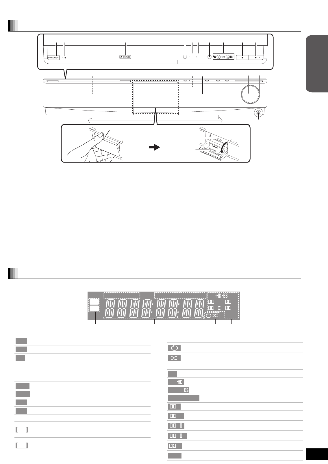
Main unit
Place your finger on the 4 section
and open it diagonally downwards.
BOOST
7.1CH
SW
SELECTOR
D.S.P.
Getting started
! POWER button (POWER Í/I) (> 14)
Press to switch the unit from on to standby mode or vice-versa. In
standby mode, the unit is still consuming a small amount of power.
@ Standby/on indicator (Í)
When the unit is connected to the household AC outlet, this
indicator lights up in standby mode and goes out when the unit is
turned on.
# Open or close the disc tray (> 14)
$ SW BOOST (Subwoofer boost) button
Turn Subwoofer boost on/off (> 26)
% SW BOOST (Subwoofer boost) indicator
Lights when Subwoofer boost is on (> 26)
^ 7.1CH D.S.P. indicator
Illuminated during 7.1ch source playback.
& Select the source
BD/DVD/CD") SD") FM")AM")IPOD")D-IN")AUX
^"""""""""""""""""""""""""""""""b
The unit’s display
iPod
DISC
W2S
W4S
! Drive indicator
DISC
iPod
SD
≥The indicator blinks when reading data.
@ SLEEP indicator (> 16)
# Radio broadcast display
TUNED
$ Wireless link indicator
≥
Lights when disc is ready to play.
Lights when iPod is ready to play.
Lights when SD card is ready to play.
Lights when receiving a radio broadcast (> 18)
Lights when set to monaural reception (> 18)
MONO
Lights when set to stereo broadcast reception (> 18)
ST
Flashes during preset channel registration (> 9)
M
Lights when speaker setting (> 33, Speaker, 34,
Speaker settings) is set to 5.1ch and link with wireless
W2S
system is activated
Lights when speaker setting (> 33, Speaker, 34,
Speaker settings) is set to 7.1ch and link with wireless
W4S
system is activated
The indicator blinks when the wireless link is inactive for a long time.
SD
* Select the radio station manually (> 18)
Search/Slow-motion/Skip (> 15)
Search: Press and hold (During play)
Slow-motion: Press and hold (During pause)
Skip: Press
( Stop (> 15)
AJ Start play (> 14)
AA Disc tray (> 14)
AB Remote control signal sensor
AC Display
AD Adjust the volume of the main unit (> 14)
AE Volume indicator
≥It is possible to set the indicator to turn on/off. (> 33, FL Display)
AF SD card slot (> 14)
AG Connect iPod (> 20)
AH Headphone terminal (> 14)
Rear panel terminals
CAUTION
Do not place objects in front of the unit. The disc tray may collide with
objects when it is opened, and this may cause injury.
SLP
TUNED
MONO
(> 6–8, 35–36)
DTS
ST M
96/24
+
DD
PLxHD
NEO:6
% Main display section
^ iPod indicator
& Audio signal indicator
DTS
DTS
DTS
DTS
NEO:6
Illuminated during iPod repeat playback (EXTENDED
mode only, > 21)
Illuminated during iPod shuffle playback (EXTENDED
mode only, > 21)
96/24
D
+
D
PL
PL
x
HD
Lights when DTS decoder is being used.
Lights when DTS-HD decoder is being used.
Lights when DTS-ES decoder is being used.
Lights when DTS 96/24 decoder is being used.
Lights when Dolby Digital decoder is being used.
Lights when Dolby Digital Plus decoder is being
used.
Lights when Dolby Pro Logic II decoder is being
used.
Lights when Dolby Pro Logic IIx decoder is being
used.
Lights when Dolby TrueHD decoder is being
used.
Lights when DTS NEO:6 matrix decoder is being
used.
RQT9129
11
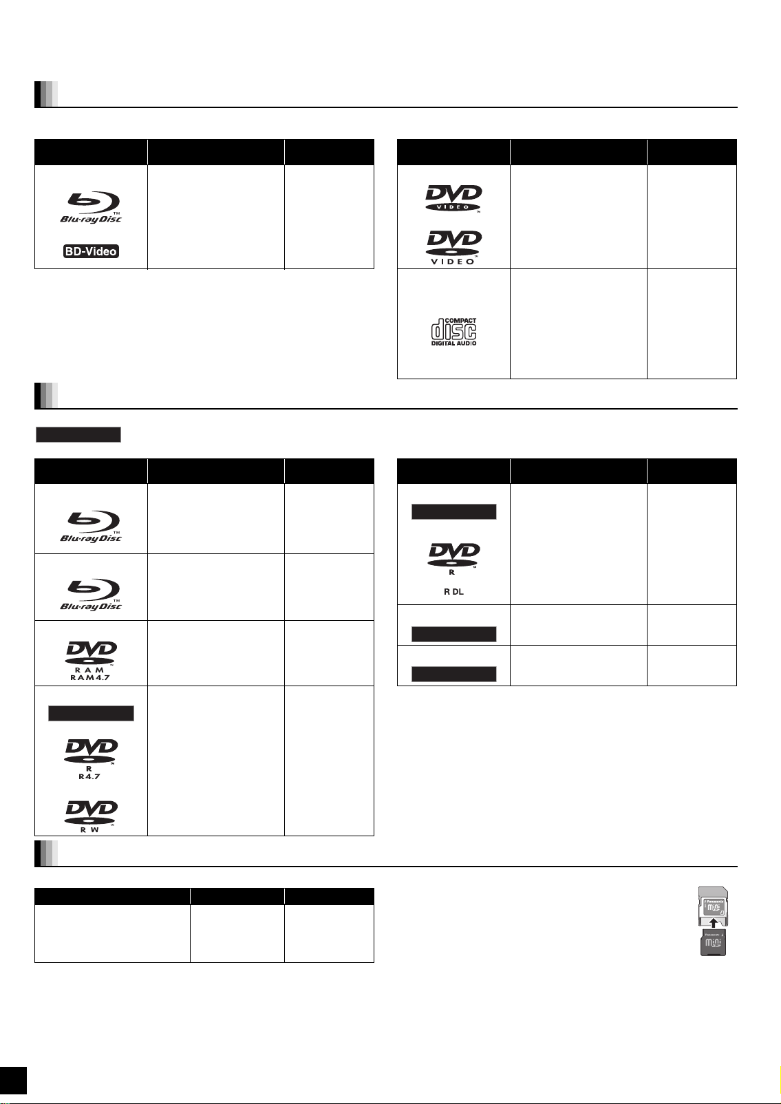
Disc and card information
Packaged discs
This chart shows the different type of retail/commercial discs you can use, and also includes the industry-standard logos that should appear on
the discs and/or packaging.
Type of media/
Logo
BD-Video
Features Indicated as Type of media/
High Definition (HD)
movie and music discs
[BD-V]
Logo
DVD-Video
Features Indicated as
High quality movie and
music discs
[DVD-V]
CD
Compact Discs (CD’s)
that contain audio and
music
≥Operation and sound
quality of CDs that do
not conform to CD-DA
specifications (copy
control CDs, etc.)
cannot be guaranteed.
[CD]
Recorded discs
This chart shows the different type of discs recorded with DVD recorders, DVD video cameras, personal computers, etc. that you can use.
Finalized
Type of media/
Logo
BD-RE
BD-R
DVD-RAM
DVD-R/RW
Finalized
This mark means you must finalize the disc with the DVD recorder, etc. before playback. For details about finalizing, refer to
the operating instructions for your equipment.
Formats Indicated as Type of media/
≥Version 3 of the
BD-RE Recording
Format
≥JPEG format
≥Version 2 of the BD-R
Recording Format
≥Version 1.1 of the DVD
Video Recording
Format
≥JPEG format
≥AVCHD format
≥DVD-Video Format
≥Version 1.1 of the DVD
Video Recording
Format
≥AVCHD format
[BD-V]
[JPEG]
[BD-V]
[DVD-VR]
[JPEG]
[AVCHD]
[DVD-V]
[DVD-VR]
[AVCHD]
Logo
DVD-R DL
Finalized
+R/+RW/+R DL
Finalized
CD-R/RW
Finalized
≥It may not be possible to play the above discs in some cases
due to the type of discs, the condition of the recording, the
recording method and how the files were created.
≥When a disc recorded in the AVCHD format is being played, the
video may be paused for a few seconds at portions spliced, due
to deletion or editing.
Formats Indicated as
≥DVD-Video Format
≥Version 1.2 of the DVD
Video Recording
Format
≥AVCHD format
≥+VR (+R/+RW Video
Recording) Format
≥AVCHD format
≥CD-DA format
≥MP3 format
≥JPEG format
[DVD-V]
[DVD-VR]
[AVCHD]
[DVD-V]
[AVCHD]
[CD]
[MP3]
[JPEG]
SD cards
This chart shows the different type of cards recorded with Panasonic High Definition Video Camera or personal computers, etc. that you can use.
Type of media Formats Indicated as
SD Memory Card
(from 8 MB to 2 GB)
§
SDHC Memory Card
(from 4 GB to 16 GB)
§
Including miniSD Card and microSD Card
≥When using from 4 GB to 16 GB SD cards, only SD cards that
display the SDHC logo can be used.
≥This unit is compatible with SD Memory Cards that meet SD Card
Specifications FAT12 and FAT16 formats, as well as SDHC Memory
Cards in FAT32 format.
≥In these operating instructions, the cards shown in the table
(D above) are comprehensively called SD cards.
≥JPEG format
≥AVCHD
format
[JPEG]
[AVCHD]
≥A miniSD Card and a microSD Card must be used with the
attached adaptor that comes with the card.
≥Useable memory is slightly less than the card capacity.
≥If the SD card is formatted on a PC, you may not be able to
use it on this unit. In this case, format the card on this unit
(> 24).
≥We recommend using a Panasonic SD card.
≥Keep the Memory Card out of reach of children to prevent
swallowing.
≥When a card recorded in the AVCHD format is being played, the
video may be paused for a few seconds at portions spliced, due to
deletion or edition.
≥Switch the write-protect switch to the “LOCK” position to protect the
content from accidental erasure.
ADAPTER
Regarding BD-Video
≥Enjoy Final Standard Profile functions (> 24), such as picture-in-picture. The various functions differ depending on the disc.
≥When playing a set of two or more BD-Video discs, the menu screen may continue to display even if the disc has been ejected.
≥Dolby TrueHD, Dolby Digital Plus, DTS-HD Master Audio and DTS-HD High Resolution Audio are output as Dolby Digital when “BD-Video
Secondary Audio” (> 33) is set to “On”.
Note about using a DualDisc
The digital audio content side of a DualDisc does not meet the technical specifications of the Compact Disc Digital Audio (CD-DA) format so play
may not be possible.
Tips for making MP3/JPEG discs
File format MP3 JPEG
Playable media
CD-R/RW
Extension Files must have the extension “.mp3” or “.MP3”. Files must have the extension “.jpg” or “.JPG”.
Picture resolution — between 34k34 and 5120k3840 pixels
Bit rates 32 kbps to 320 kbps —
Sampling frequency 44.1 kHz/48 kHz —
Reference ID3 tags: version 1, 2.2, 2.3, 2.4
ID3 is a tag embedded in MP3 track to provide information
about the track.
This unit supports the versions listed above but only titles
and the names of artists can be displayed.
≥If there is a large amount of still picture data etc. within a
≥English alphabet and Arabic numerals are displayed correctly. Other characters may not be displayed correctly.
≥The display order on this unit may differ from how the order is displayed on a computer.
≥Depending on how you create the media (writing software), files and folders may not play in the order you numbered
≥This unit is not compatible with packet-write format.
≥Depending on the recording conditions, the media may not play.
≥Operation may take time to complete when there are many files and/or folders and some files may not display or be
§1
ISO9660 level 1 or 2 (except for extended formats), Joliet
This unit is compatible with multi-session.
This unit is not compatible with packet writing.
§2
Discs must conform to UDF 2.0.
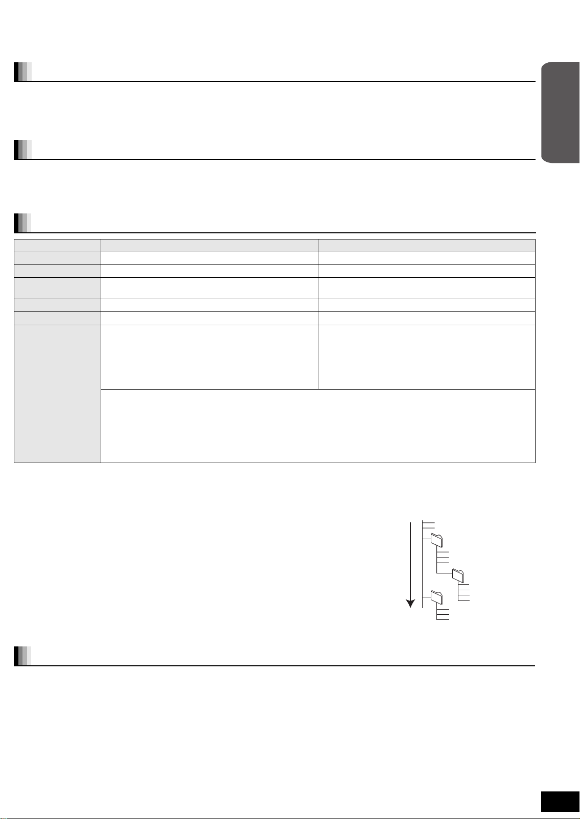
Structure of MP3 and still pictures (JPEG) folders
You can play MP3 and still pictures (JPEG) with this unit by making folders on disc as shown
(D right).
≥Folder structure created on a DVD-RAM, BD-RE or an SD card is not displayed.
MP3 files and folders in CD-R/RW
Prefix with 3-digit numbers in the order you want to play them.
Still pictures (JPEG) in CD-R/RW
Files inside a folder are displayed in the order they were updated or taken.
When the highest level folders are “DCIM” folders, they are displayed first on the tree.
§1
MP3 file, play may not be possible.
them.
playable.
CD-R/RW§1, DVD-RAM§2, BD-RE§3, SD card
(sub sampling is 4:2:2 or 4:2:0)
≥MOTION JPEG: not supported
≥SD card: JPEG conforming DCF
§4
(Design rule for
Camera File system)
Thawing Time: approx. 2 sec. (7M pixels)
§3
Discs must conform to UDF 2.5.
§4
Design rule for Camera File system: unified standard established
by Japan Electronics and Information Technology Industries
Association (JEITA).
Root
e.g.,
Order of play
P0000001.jpg
P0000002.jpg
002 Folder
001
004 Folder
P0000003.jpg
P0000004.jpg
P0000005.jpg
003 Folder
P0000006.jpg
P0000007.jpg
P0000008.jpg
P0000009.jpg
P0000010.jpg
P0000011.jpg
P0000012.jpg
Getting started
Discs that cannot be played
≥BD-Video discs recorded at a rate of 50 frame per second
≥BD-RE with the cartridge
≥DVD-RAM that cannot be removed from their cartridges
≥2.6 GB and 5.2 GB DVD-RAM
≥3.95 GB and 4.7 GB DVD-R for Authoring
≥Version 1.0 of DVD-RW
≥+R 8 cm (3z), DVD-ROM, CD-ROM, CDV, SACD, Photo CD,
MV-Disc and PD
≥DVD-Audio
≥Video CD and SVCD
≥WMA discs
≥DivX discs
≥PA L d is cs
≥HD DVD
≥Other discs that are not specifically supported
RQT9129
13

Basic play (Playing video contents)
Preparation
Turn on the TV and select the appropriate video input on the TV.
Insert a disc.
Press [< OPEN/CLOSE] to open the disc tray
and load the disc.
Label facing up
≥Press the button again to close the tray.
≥Load double-sided discs so the label for the side you
want to play is facing up.
≥DVD-RAM: Remove the discs from their cartridges
before use.
VIDEO1
Insert an SD card.
Insert the card label up
with the cut-off corner
on the right.
≥Press on the center of
the card until it clicks
into place.
≥To re mo ve the card, press on the center of the card
and pull it straight out.
Skip/Search/Slow-motion
Stop
SELECTOR
Play
`,_VOL UME
Headphones (not included)
Headphone plug type: ‰3.5 mm (
≥Reduce the volume before connecting.
≥Audio is automatically switched to 2-channel stereo.
≥To p re vent hearing damage, avoid listening for prolonged periods of time.
Excessive sound pressure from earphones and headphones can cause hearing loss.
1
/8z) stereo mini plug
1 Press [Í] to turn on the unit.
2 Insert a disc or an SD card (B see above).
≥If play does not start, press [1](PLAY).
≥If the screen prompting you to use the color buttons appears, continue to operate with the color buttons on the remote control.
≥If the menu is displayed, press [3, 4, 2, 1] to select the item and press [OK].
e.g., [BD-V]
MAIN MENU
SCENE SELECTION LANGUAGES
SPECIAL FEATURES
e.g., [DVD-VR]
DIRECT NAVIGATOR Title View
DVD-RAM(VR)
Date Day
No.
9/ 5
01
9/ 5
02
9/ 5
03
Rec. Length
0:15 (SP)
04
9/ 6
9/ 6
05
9/ 6
06
9/ 7
07
9/ 7
08
9/ 7
09
9/ 7
10
Play
SUB
Video Picture
A B
MENU
RETURN
Wed
Wed
Wed
Thu
Thu
Thu
Fri
Fri
Fri
Fri
Channel
10:00AM
IN 2
11:30AM
IN 2
VHS
10:00AM
VHS
11:30AM
10:00AM
10:30AM
IN 2
11:30AM
IN 2
Previous Next
Start
11:59PM
11:59PM
11:59PM
Video
Picture
Title Name
Page 01/02
≥DISCS CONTINUE TO ROTATE WHILE MENUS ARE DISPLAYED.
Press [∫] when you have finished playback to protect the unit’s motor, your TV screen and so on.
NOTE
To switch drives
Press [BD/SD] to select “BD/DVD/CD” or “SD”.
Main unit: Press [SELECTOR].
TIPS
≥If a disc or an SD card is inserted while the unit is stopped, the drive switches
automatically depending on the inserted media.
To display menus
[BD-V] [AVCHD] [DVD-VR] [DVD-V]
Press [TOP MENU/DIRECT NAVIGATOR].
≥The producers of the disc can control how discs are played. So you may not always be able to control play as described in these
operating instructions. Read the disc’s instructions carefully.
e.g., “BD/DVD/CD”
e.g., SD card containing pictures
(JPEG) and HD movies (AVCHD)
SD Card
Picture (JPEG) Navigator
Playback HD Movie (AVCHD)
Select an action or press [RETURN].
SUB
MENU
e.g., “SD”
OK
RETURN
Other operations during play (These functions may not work depending on the disc.)
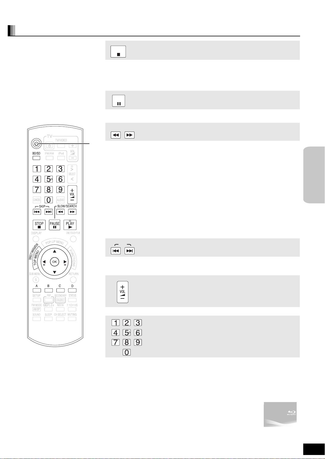
STOP
The stopped position is memorized.
Resume play function
Press [1] (PLAY) to restart from this position.
≥The position is cleared if the tray is opened or you press
on unit’s display.
PAUSE
≥Press [;] again or [1] (PLAY) to restart play.
SLOW/SEARCH
Stop
[∫] several times to display “STOP”
Pause
Search/Slow-motion
The speed increases up to 5 steps.
≥Press [1] (PLAY) to revert to normal playback speed.
≥For some discs, the speed may not change.
Search
While playing, press [6] or [5].
≥Press and hold [:/6] or [9/5] on the main unit.
≥[BD-V] [AVCHD] [DVD-VR] [DVD-V]:
Audio is heard during first level of forward search.
≥[CD] [MP3]: The speed is fixed to a single step.
Slow-motion
While paused, press [6] or [5].
≥Press and hold [:/6] or [9/5] on the main unit.
≥[BD-V] [AVCHD]: Forward direction [5] only.
≥[DVD-VR]: If continued for approx. 5 minutes, slow-motion play pauses automatically.
Basic
operations
SKIP
Skip to the title, chapter or track you want to play.
≥Each press increases the number of skips.
Skip
Adjust the volume
Starting from a selected item
Play starts from the selected title or chapter.
[BD-V] [AVCHD]
e.g., 5: [0] B [0] B [5]
15: [0] B [1] B [5]
[DVD-V]
e.g., 5: [0] B [5]
15: [1] B [5]
≥While stopped (the image on the right is displayed on the screen), the title
is designated. While playing, the chapter is designated.
(Continued on the next page)
RQT9129
15
 Loading...