

Panasonic SC-BT07 User Manual
Operating Instructions
Blu-ray Disc Home Theater Sound System
Model No. SC-BT207
Dear customer
Thank you for purchasing this product.
For optimum performance and safety, please read these instructions carefully.
Before connecting, operating or adjusting this product, please read the instructions completely. Please keep this manual for
future reference.
To update the firmware of this unit, refer to page 33.
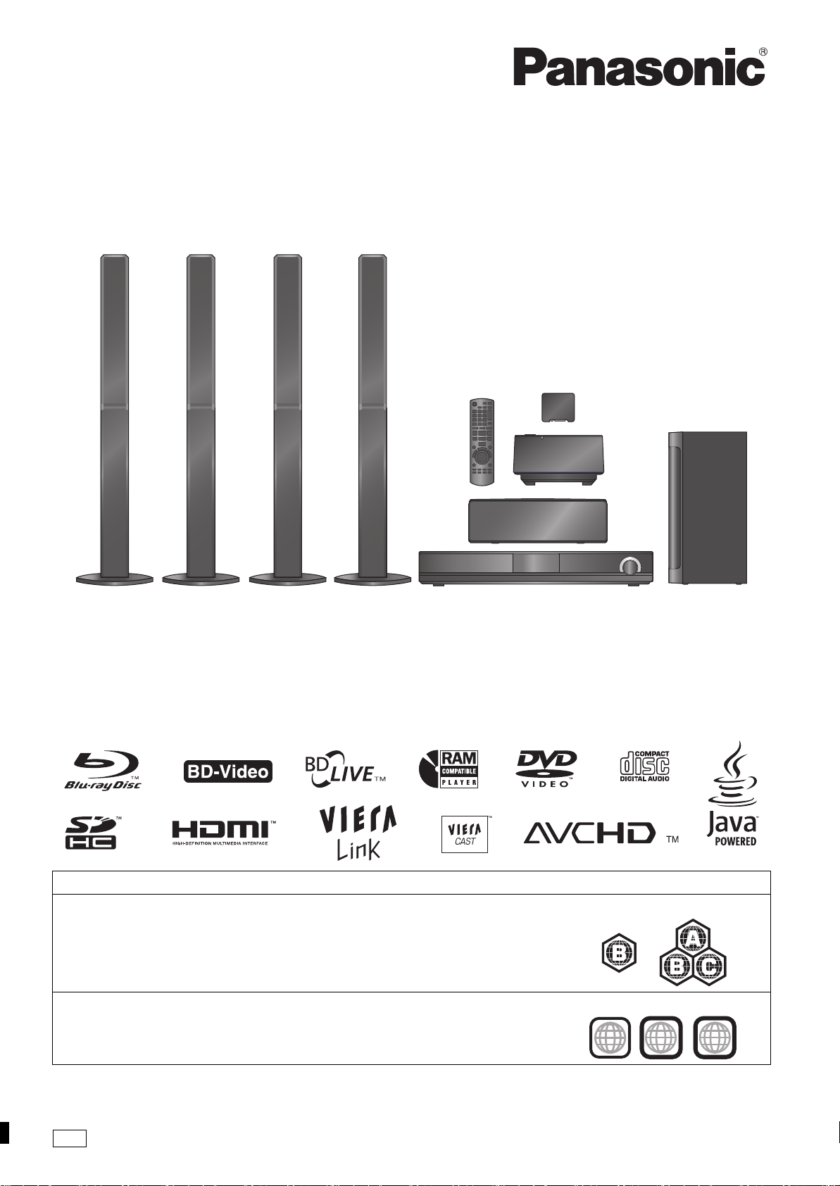
Region management information
BD-Video
This unit plays BD-Video marked with labels containing the region code B.
DVD-Video
This unit plays DVD-Video marked with labels containing the region number “4” or “ALL”.
Example:
Example:
4
ALL
1
2
4
GN
RQT9483-2L
≥Please note that the actual controls and components, menu
items, etc. of your Blu-ray Disc Home Theater Sound System
Getting started
may look somewhat different from those shown in the
illustrations in these Operating Instructions.
≥Operations in these instructions are described mainly with the
remote control, but you can perform the operations on the
main unit if the controls are the same.
System SC-BT207
Main unit SA-BT207
Front speakers SB-HF770
Center speaker SB-HC300
Surround speakers SB-HS870
Subwoofer SB-HW200
Digital transmitter SH-TR70
Wireless system SE-FX70
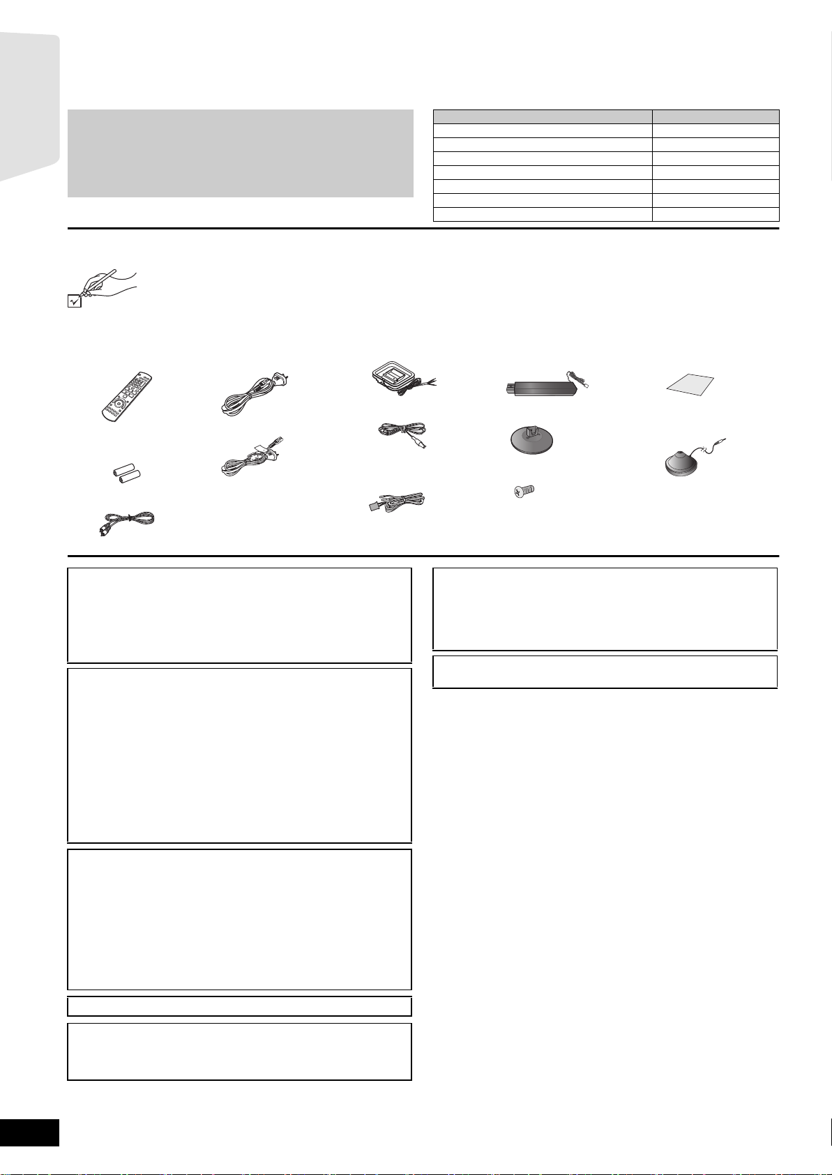
Accessories
Please check and identify the supplied accessories. Use numbers indicated in parentheses when asking for replacement parts.
(Product numbers correct as of April 2009. These may be subject to change.)
∏ 1 Remote control
(N2QAKB000073)
∏ 2 AC mains leads
For the main unit
∏ 1 AM loop antenna
∏ 4 Speaker stands
(with cable)
∏ 1 Sheet of speaker
cable stickers
∏ 1 FM indoor antenna
∏ 2 Remote control
batteries
∏ 1 Video cable
For the wireless system
≥For use with this unit only.
Do not use it with other
equipment. Also, do not use
cords from other equipment
with this unit.
∏ 1 Speaker cable
(center) (Green)
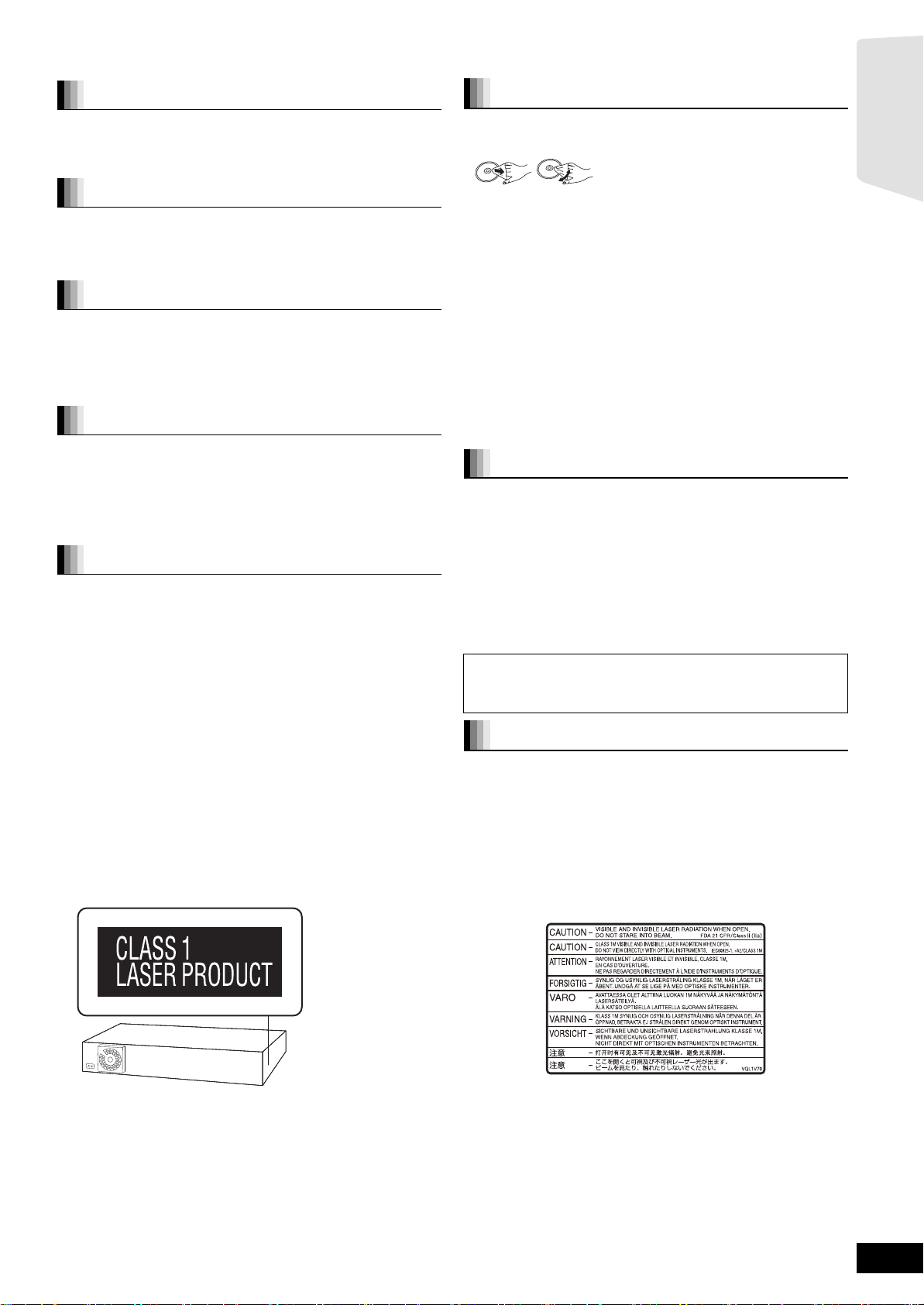
CAUTION!
THIS PRODUCT UTILIZES A LASER.
USE OF CONTROLS OR ADJUSTMENTS OR PERFORMANCE
OF PROCEDURES OTHER THAN THOSE SPECIFIED HEREIN
MAY RESULT IN HAZARDOUS RADIATION EXPOSURE.
DO NOT OPEN COVERS AND DO NOT REPAIR YOURSELF.
REFER SERVICING TO QUALIFIED PERSONNEL.
CAUTION!
≥DO NOT INSTALL OR PLACE THIS UNIT IN A BOOKCASE,
BUILT-IN CABINET OR IN ANOTHER CONFINED SPACE.
ENSURE THE UNIT IS WELL VENTILATED. TO PREVENT
RISK OF ELECTRIC SHOCK OR FIRE HAZARD DUE TO
OVERHEATING, ENSURE THAT CURTAINS AND ANY OTHER
MATERIALS DO NOT OBSTRUCT THE VENTILATION VENTS.
≥DO NOT OBSTRUCT THE UNIT’S VENTILATION OPENINGS
WITH NEWSPAPERS, TABLECLOTHS, CURTAINS, AND
SIMILAR ITEMS.
≥DO NOT PLACE SOURCES OF NAKED FLAMES, SUCH AS
LIGHTED CANDLES, ON THE UNIT.
≥DISPOSE OF BATTERIES IN AN ENVIRONMENTALLY
FRIENDLY MANNER.
∏ 4 Bases
∏ 16 Screws
The socket outlet shall be installed near the equipment and easily
accessible.
The mains plug of the power supply cord shall remain readily
operable.
To completely disconnect this apparatus from the AC Mains,
disconnect the power supply cord plug from AC receptacle.
For wireless system
Product Identification Marking is located on the bottom of unit.
∏ 1 Auto speaker setup
microphone
RQT9483
2
WARNING:
TO REDUCE THE RISK OF FIRE, ELECTRIC SHOCK OR
PRODUCT DAMAGE,
≥DO NOT EXPOSE THIS APPARATUS TO RAIN, MOISTURE,
DRIPPING OR SPLASHING AND THAT NO OBJECTS FILLED
WITH LIQUIDS, SUCH AS VASES, SHALL BE PLACED ON
THE APPARATUS.
≥USE ONLY THE RECOMMENDED ACCESSORIES.
≥DO NOT REMOVE THE COVER (OR BACK); THERE ARE NO
USER SERVICEABLE PARTS INSIDE. REFER SERVICING TO
QUALIFIED SERVICE PERSONNEL.
THIS UNIT IS INTENDED FOR USE IN MODERATE CLIMATES.
This product may receive radio interference caused by mobile
telephones during use. If such interference is apparent, please
increase separation between the product and the mobile
telephone.
Safety precautions
DO
DO NOT
Unit and media care
Placement
Set the unit up on an even surface away from direct sunlight, high
temperatures, high humidity, and excessive vibration. These
conditions can damage the cabinet and other components, thereby
shortening the unit’s service life. Do not place heavy items on the unit.
Voltag e
Do not use high voltage power sources. This can overload the unit and
cause a fire. Do not use a DC power source. Check the source
carefully when setting the unit up on a ship or other place where DC is
used.
AC mains lead protection
Ensure the AC mains lead is connected correctly and not damaged.
Poor connection and lead damage can cause fire or electric shock. Do
not pull, bend, or place heavy items on the lead.
Grasp the plug firmly when unplugging the lead. Pulling the AC mains
lead can cause electric shock. Do not handle the plug with wet hands.
This can cause electric shock.
Foreign matter
Do not let metal objects fall inside the unit. This can cause electric
shock or malfunction.
Do not let liquids get into the unit. This can cause electric shock or
malfunction. If this occurs, immediately disconnect the unit from the
power supply and contact your dealer.
Do not spray insecticides onto or into the unit. They contain flammable
gases which can ignite if sprayed into the unit.
Service
Do not attempt to repair this unit by yourself. If sound is interrupted,
indicators fail to light, smoke appears, or any other problem that is not
covered in these instructions occurs, disconnect the AC mains lead
and contact your dealer or an authorized service center. Electric shock
or damage to the unit can occur if the unit is repaired, disassembled or
reconstructed by unqualified persons.
Extend operating life by disconnecting the unit from the power source
if it is not to be used for a long time.
Disc and card handling
Clean discs
Getting started
Wipe with a damp cloth and then wipe dry.
Disc and card handling precautions
≥Handle discs by the edges to avoid inadvertent scratches or
fingerprints on the disc.
≥Do not attach labels or stickers to discs (This may cause disc
warping, rendering it unusable).
≥Do not write on the label side with a ball-point pen or other writing
instrument.
≥Do not use record cleaning sprays, benzine, thinner, static electricity
prevention liquids or any other solvent.
≥Do not use scratch-proof protectors or covers.
≥Clean any dust, water, or foreign matter from the terminals on the
rear side of the card.
≥Do not use the following discs:
– Discs with exposed adhesive from removed stickers or labels
(rented discs etc).
– Discs that are badly warped or cracked.
– Irregularly shaped discs, such as heart shapes.
Maintenance
Clean this unit with a soft, dry cloth
≥Never use alcohol, paint thinner or benzine to clean this unit.
≥Before using chemically treated cloth, carefully read the instructions
that came with the cloth.
Observe the following points to ensure continued
listening and viewing pleasure.
Dust and dirt may adhere to the unit’s lens over time, making it
impossible to play discs.
Use the lens cleaner (not included) about once every year, depending
on frequency of use and the operating environment. Carefully read the
lens cleaner’s instructions before use.
Lens cleaner: RP-CL720E
≥This lens cleaner may not be for sale depending on the region.
≥This lens cleaner is sold as specific for DIGA, but can be used
without problem on this unit as well.
To dispose or transfer this unit
This unit may record information of your operating procedures. If you
discard this unit either by disposal or transfer, then follow the
procedures to return all the settings to the factory presets to delete the
recorded information. (> 48, “To return to the factory preset”)
≥When BD-Video is played back, the operation history may be
recorded in the memory of this unit. The recorded contents differ
depending on the disc.
(Inside of product)
RQT9483
3
Table of contents
Getting started
Accessories........................................................2
Getting started TV Radio PlaybackOther devices
Safety precautions .............................................3
Unit and media care...........................................3
Using the remote control ..................................5
Batteries ................................................................. 5
Use ......................................................................... 5
Control reference guide (remote control) ........5
Control reference guide (main unit) .................6
Front panel ............................................................. 6
Rear panel terminals .............................................. 6
Assembling the speakers...............................7
Positioning ......................................................8
Speaker connections......................................9
TV connections .............................................10
Connections with a video cable ...............................10
Connections with a component video cable...........11
Connections with a HDMI cable ...............................11
Connections to a Set Top Box, etc..............12
Radio antenna connections .........................12
Network connection......................................13
AC mains lead connection ...........................14
Preparing the wireless system ....................14
SMART SETUP ..............................................15
Basic setting for the system (SMART SETUP) .......15
Showing START menu.....................................16
Selecting the playback source .......................17
Selecting the source from the START menu........ 17
Selecting the source by the remote control .......... 17
Enjoying sound from all speakers and
various sound effects ....................................18
Enjoying surround sound effects .......................... 18
Changing the sound modes.................................. 18
Adjusting speaker level during play...................... 18
Playback
Basic operation ................................................19
Other operations during play ................................ 20
Playing video recorded on a Video Camera or
Video Recorder .................................................. 21
Enjoying BD-LIVE or BONUSVIEW
Advanced operations
settings
in BD-Video.....................................................22
Playing secondary video (picture-in-picture) and
secondary audio................................................. 22
Enjoying BD-Live discs with Internet .................... 22
Playing DivX® videos .......................................23
Regarding DivX VOD content............................... 23
Displaying subtitles text ........................................ 23
Playing still pictures ........................................24
Useful functions during still picture play ............... 25
Playing music...................................................26
TV
Enjoying TV, etc. with this unit’s speakers ...28
Enjoying TV and other devices sound from
this unit’s speakers............................................. 28
Adjusting the sound.............................................. 28
Making settings for digital audio input .................. 28
Linked operations with the TV (VIERA Link
“HDAVI Control
What is VIERA Link “HDAVI Control”? ................. 29
What you can do with “HDAVI Control” ................ 29
Easy control only with VIERA remote control ....... 30
TM
”) ........................................ 29
Other devices
Using the iPod ................................................. 31
iPod Connection ................................................... 31
iPod Playback....................................................... 32
Advanced operations
Enjoying VIERA CASTTM.................................. 33
Firmware updating........................................... 33
Network settings.............................................. 34
Changing settings with the on-screen menu.... 36
On-screen menu operations................................. 36
What you can change with the on-screen menu .. 36
Changing the unit’s settings ..........................38
Setup menu operations ........................................38
Summary of settings.............................................38
Speaker settings...................................................42
Optional speaker settings
Speaker installation option.............................43
Reference
Media (Disc, card and USB device)
information..................................................... 44
Packaged discs .................................................... 44
Recorded discs..................................................... 44
SD cards............................................................... 45
USB device........................................................... 45
Regarding 24p output........................................... 45
Discs that cannot be played ................................. 45
About MP3/JPEG/DivX files ............................ 46
Troubleshooting guide.................................... 48
Messages ......................................................... 52
Frequently asked questions ........................... 53
Language code list .......................................... 54
Licenses ........................................................... 54
Glossary ........................................................... 55
Specifications .................................................. 57
Index ..................................................Back cover
Radio
Listening to the Radio .....................................27
Reference Optional speaker
RQT9483
4
Setting up the radio .............................................. 27
Listening/confirming the preset channels ............. 27
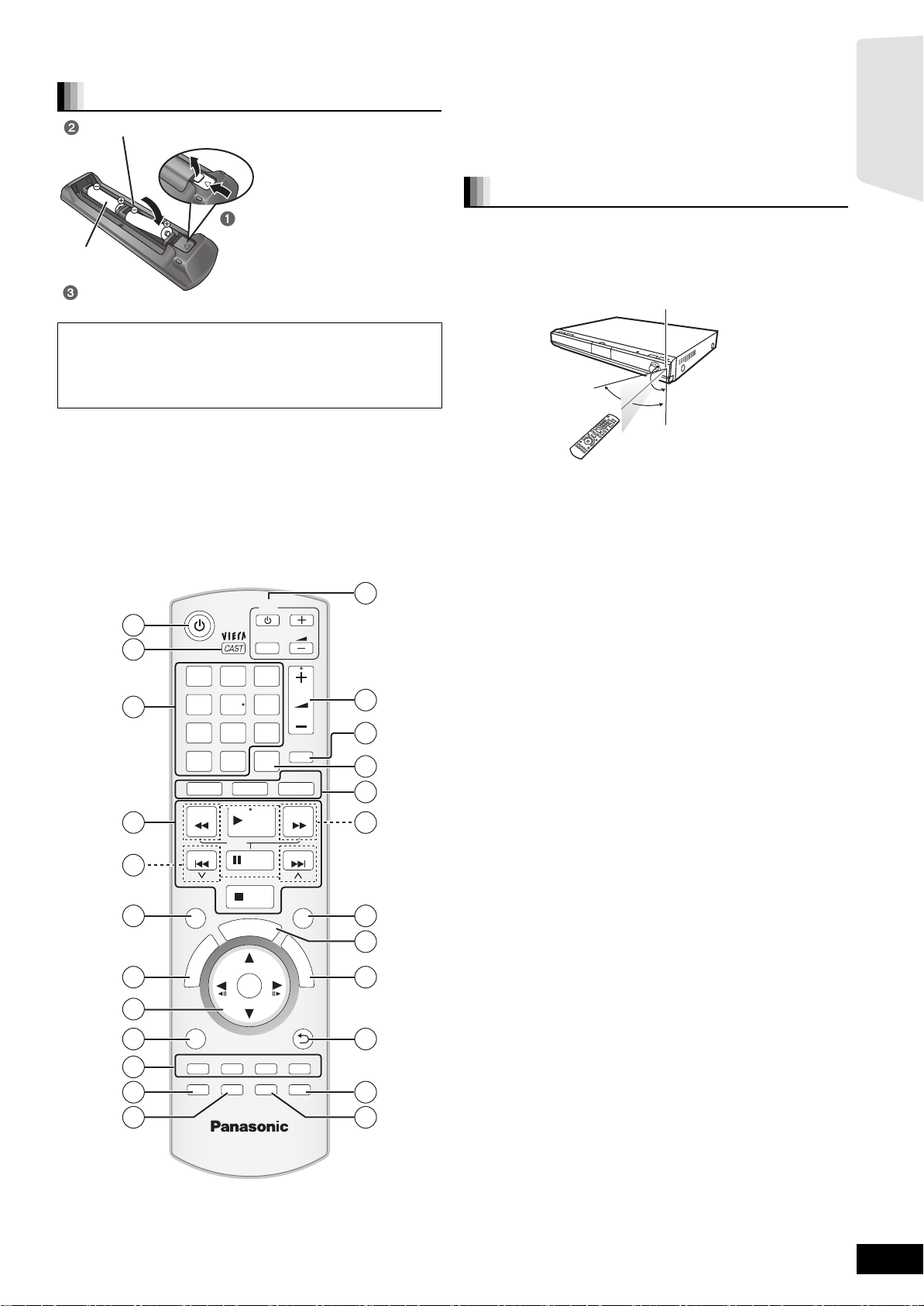
Using the remote control
≥Do not take apart or short circuit.
Batteries
I
Insert so the poles ( and ) match those in the remote control.
Press in and lift up.
R6/LR6, AA
Replace the lid.
When closing the lid, insert it from the (minus) side.
CAUTION
Danger of explosion if battery is incorrectly replaced.
Replace only with the same or equivalent type recommended by the
manufacturer. Dispose of used batteries according to the
manufacturer’s instructions.
≥Use alkaline or manganese batteries.
≥Do not mix old and new batteries.
≥Do not use different types at the same time.
≥Do not heat or expose to flame.
≥Do not leave the battery(ies) in an automobile exposed to direct
sunlight for a long period of time with doors and windows closed.
≥Do not attempt to recharge alkaline or manganese batteries.
≥Do not use batteries if the covering has been peeled off.
Mishandling of batteries can cause electrolyte leakage which can
damage items the fluid contacts and may cause a fire.
Remove batteries if the remote control is not going to be used for a
long period of time. Store in a cool, dark place.
Aim at the remote control signal sensor (> 6), avoiding obstacles, at a
maximum range of 7 m directly in front of the unit.
≥If you cannot operate the unit or other equipment using the remote
control after changing the batteries, please re-enter the codes
(> 51).
The distance and the angles are approximate.
Use
Remote control signal sensor
20˚
30˚
20˚
30˚
7 m directly in front of the unit
Getting started
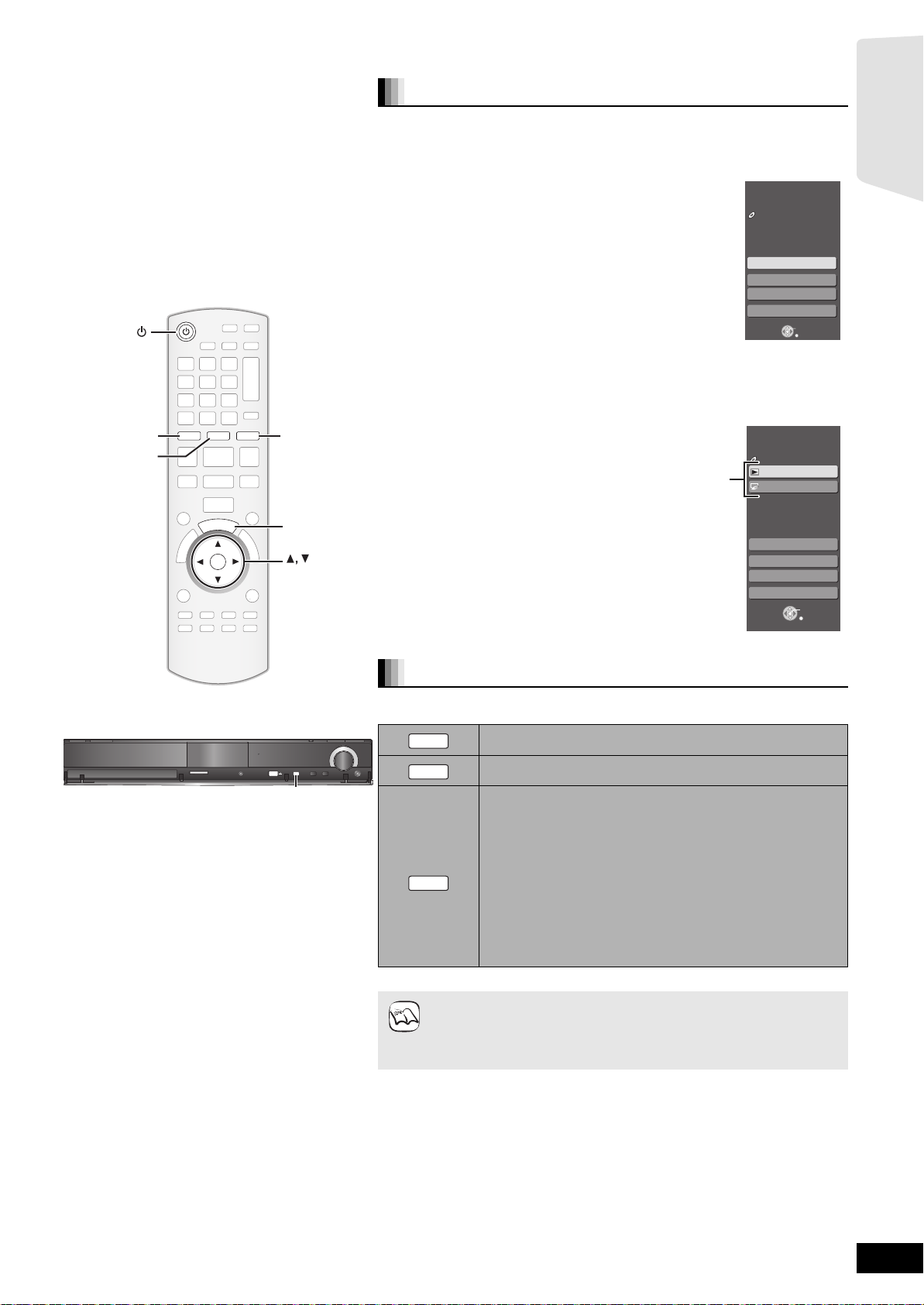
Control reference guide (remote control)
1 Turn the unit on and off (> 15)
2 Display Home screen of VIERA CAST (> 33)
3 Select title numbers, etc./Enter numbers or characters (> 20, 35)
(The character buttons may be used when operating VIERA CAST
contents. B 33)
[CANCEL]: Cancel
4 Basic playback control buttons (> 19, 20)
5 Select preset radio stations (> 27)
6 Select surround sound effects (> 18)
7 Show Top menu/Direct Navigator (> 19)
8 [3, 4, 2, 1]: Menu selection
[OK]: Selection
[2, 1]: Select preset radio station (> 27)
[2] (2;), [1] (;1): Frame-by-frame (> 20)
9 Show OPTION menu (> 20)
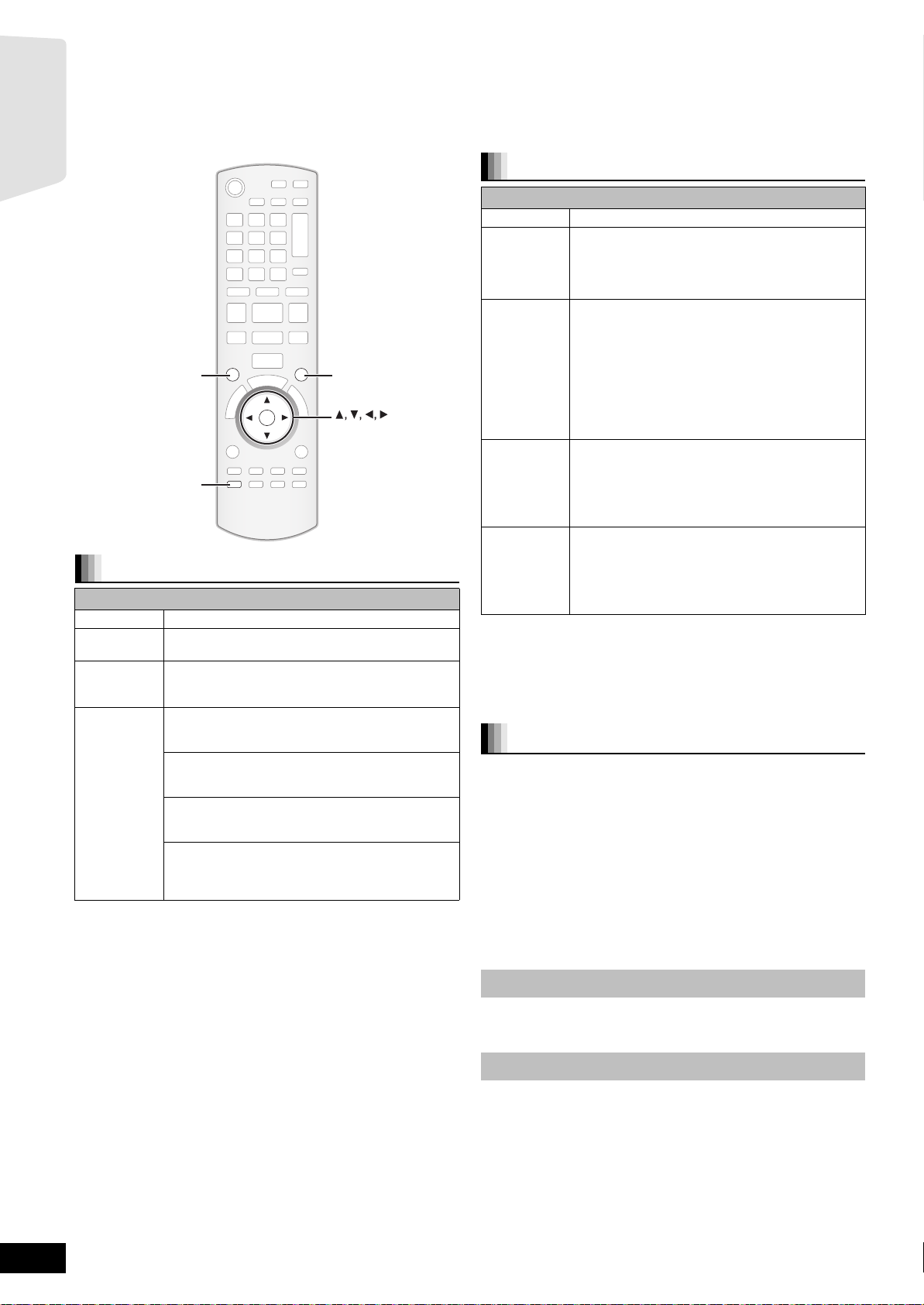
: [R], [G], [Y], [B]
These buttons are used when;
≥Operating a BD-Video disc that includes Java
(BD-J). For more information about operating this kind of disc,
please read the instructions that came with the disc.
≥Displaying “Title View”, and “Album View” screens. (Only the [R]
and [G] buttons B 24)
≥Operating contents of VIERA CAST (> 33)
; Show Setup menu (> 38)/Select speaker channel (> 18)
< Show status messages (> 21)
= TV operation buttons
You can operate the TV through the unit’s remote control.
[Í] : Turn the television on and off
[AV] : Switch the input select
[ijVOL]: Adjust the TV volume
> Adjust the volume of the main unit (> 19)
? Mute the sound (> 19)
@ Switch on/off Secondary Video (Picture-in-picture) (> 22)
A Select the source
[BD/SD]:Select disc drive or SD card drive (> 17)
[iPod]:Select iPod as the source (> 17, 31)
[RADIO/EXT-IN]:Select FM/AM tuner, USB or external audio as the
source (> 17, 27, 28)
B Select radio stations manually (> 27)
C Set the sound mode (> 18)
D Show start menu (> 16)
E Show Pop-up menu (> 19)
F Return to previous screen
G Select audio (> 20)
H Show on-screen menu (> 36)/Set the sleep timer (> 21)
1
2
3
4
5
6
7
8
9
10
11
12
1 2 3
CANCEL
SURROUND
N
T
C
E
R
I
D
OPTION
SETUP
-
CH SELECT
abc
ghi
jkl
4 5 6
p
tuv
qrs
7 809
BD/SD
SEARCH
SLOW
SKIP
S
R
O
T
A
U
G
I
N
V
A
E
M
P
O
T
R
G
STATUS
iPod
PLAY
PAU SE
STOP
A
T
OK
TV
AV
PIP
R
T
Y
DISPLAY
-
SLEEP
def
mno
w
xyz
VOL
VOL
MUTE
RADIO
EXT-IN
SEARCH
SKIP
SOUND
P
O
P
-
U
P
M
E
N
U
RETURN
B
AUDIO
13
14
15
16
17
18
19
20
21
22
23
24
TM
applications
RQT9483
5
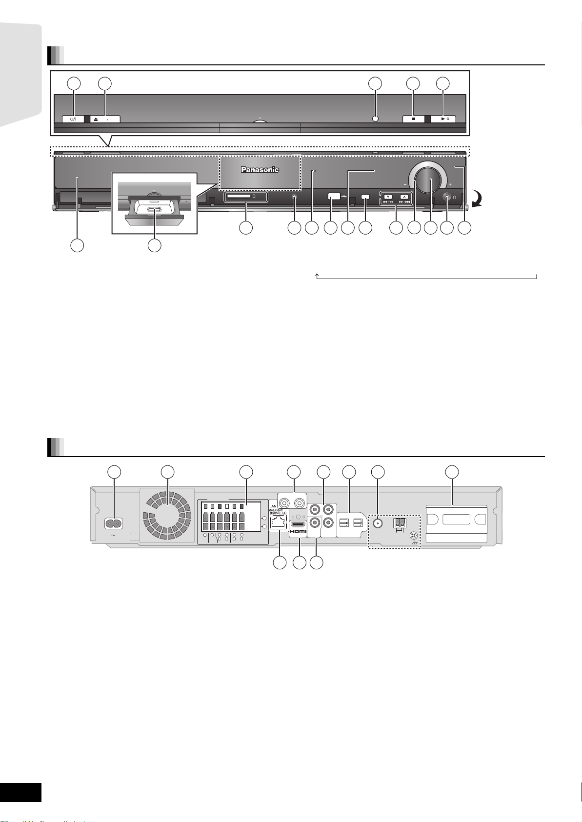
Control reference guide (main unit)
Front panel
1
2
Getting started
OPEN CLOSE
Dock for iPod
76
1 Standby/on switch (Í/I) (> 15)
Press to switch the unit from on to standby mode or vice versa. In
standby mode, the unit is still consuming a small amount of power.
2 Open or close the disc tray (> 19)
3 SMART SETUP button (> 15)
4 Stop (> 20)
5 Start play (> 19)
6 Disc tray (> 19)
7 Connect iPod (> 31)
8 SD card slot (> 19)
9 Connect Auto speaker setup microphone (> 15)
: The indicator lights when there is surround sound effect. (> 18)
; USB port (> 19)
< Display
Dock for iPod
SURROUND OUTPUT
SD CARD
SETUP MIC
8 119 10 1412
= Select the source
BD/DVD )SD )IPOD )FM )AM )USB )AUX )D-IN 1 )D-IN 2
“SD” and “USB” on the unit’s display is not displayed when the SD
card or USB device is not in the SD card slot or USB port.
> Skip or slow-search play (> 20)/Select the radio stations (> 27)
? Volume indicator
≥It is possible to set the indicator to turn on/off.
(> 39, “FL Display”)
@ Adjust the volume of the main unit (> 19)
≥When pulled hard, the volume knob may come off.
≥To prevent children from swallowing the volume knob, do not pull
off the volume knob.
A Connect headphones (not included) (> 19)
B Remote control signal sensor
3 4 5
SMART SETUP
TUNE
SELECTOR
13
(
>
15
17)
16
VOLUME
Pull open.
1817
Rear panel terminals
1
AC IN
2
SPEAKERS
5
6
3
Ω
3Ω3
SUB-
CENTER
WOOFER
1 AC IN terminal (> 14)
2 Cooling fan
3 SPEAKERS terminal (> 9)
4 AUX (TV) terminal (> 10, 11)
This terminal can also be used for equipment other than the TV.
5 COMPONENT VIDEO OUT terminal (> 11)
6 OPTICAL DIGITAL IN terminals
Terminal 1(TV) is designated for connection with the TV. (> 10, 11)
Terminal 2(STB) can be used for connection with devices other than
the STB. (> 12)
3 4 5
214
3
Ω
3
Ω
RLR
L
FRONT
SURROUND
AUX(TV)
R
+
-
9 10 11
76
L
Y
PB
OPTICAL
P
R
2(STB) 1(TV)
COMPONENT
VIDEO
OUT
VIDEO OUT
AV OU T
DIGITAL IN
7 FM/AM Radio antenna terminal (> 12)
8 Digital transmitter dock (> 9)
9 LAN port (> 13)
: HDMI AV OUT terminal (> 11)
; VIDEO OUT terminal (> 10)
75Ω
LOOP
FM ANT ANT
AM
EXT
GNDANTLOOP
8
DIGITAL
TRANSMITTER
RQT9483
6
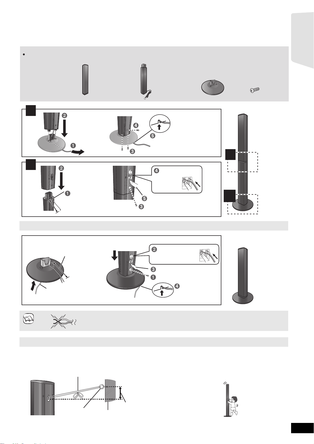
Assembling the speakers
Front speakers and Surround speakers
Preparation
≥To prevent damage or scratches, lay down a soft cloth and perform
assembly on it.
Make sure you have all the indicated components before starting assembly, setup, and connection.
Keep the screws out of reach of children to prevent swallowing.
2 Front speakers
2 Surround speakers
4 Stands
(with cables)
1
Tighten securely.
≥For assembly, use a Phillips-head screwdriver (not included).
≥For wall mount, refer to page 43.
4 Bases 16 Screws
Slide into the groove.
Getting started
2
2
Position the cable
between the ridges.
Leave about 120 mm
Speaker assembly option
Thread the speaker cable
through the base.
Leave about 120 mm
You can remove and use the cable
from the stand. To reattach the
cable, refer to page 43.
≥Be careful not to cross (short circuit) or reverse the polarity of the speaker wires as doing so may damage the
NOTE
DO
NOT
speakers.
Attach the speaker.
Insert the wire fully.
: White
: Blue
Push!
Press into the groove.
Tighten securely.
Insert the wire fully.
: White
: Blue
Press into the groove.
Tighten securely.
Push!
Slide into
the groove.
1
1
Preventing the speakers from falling
≥You will need to obtain the appropriate screw eyes to match the walls or pillars to which they are going to be fastened.
≥Consult a qualified housing contractor concerning the appropriate procedure when attaching to a concrete wall or a surface that may not have
strong enough support. Improper attachment may result in damage to the wall or speakers.
e.g.
String (not included)
Thread from the wall to the speaker and tie tightly.
Screw eye
(not included)
Rear of the speaker
Wall
Approx.
150 mm
Caution
≥Do not stand on the base. Be cautious when children are near.
e.g.
DO
NOT
RQT9483
7
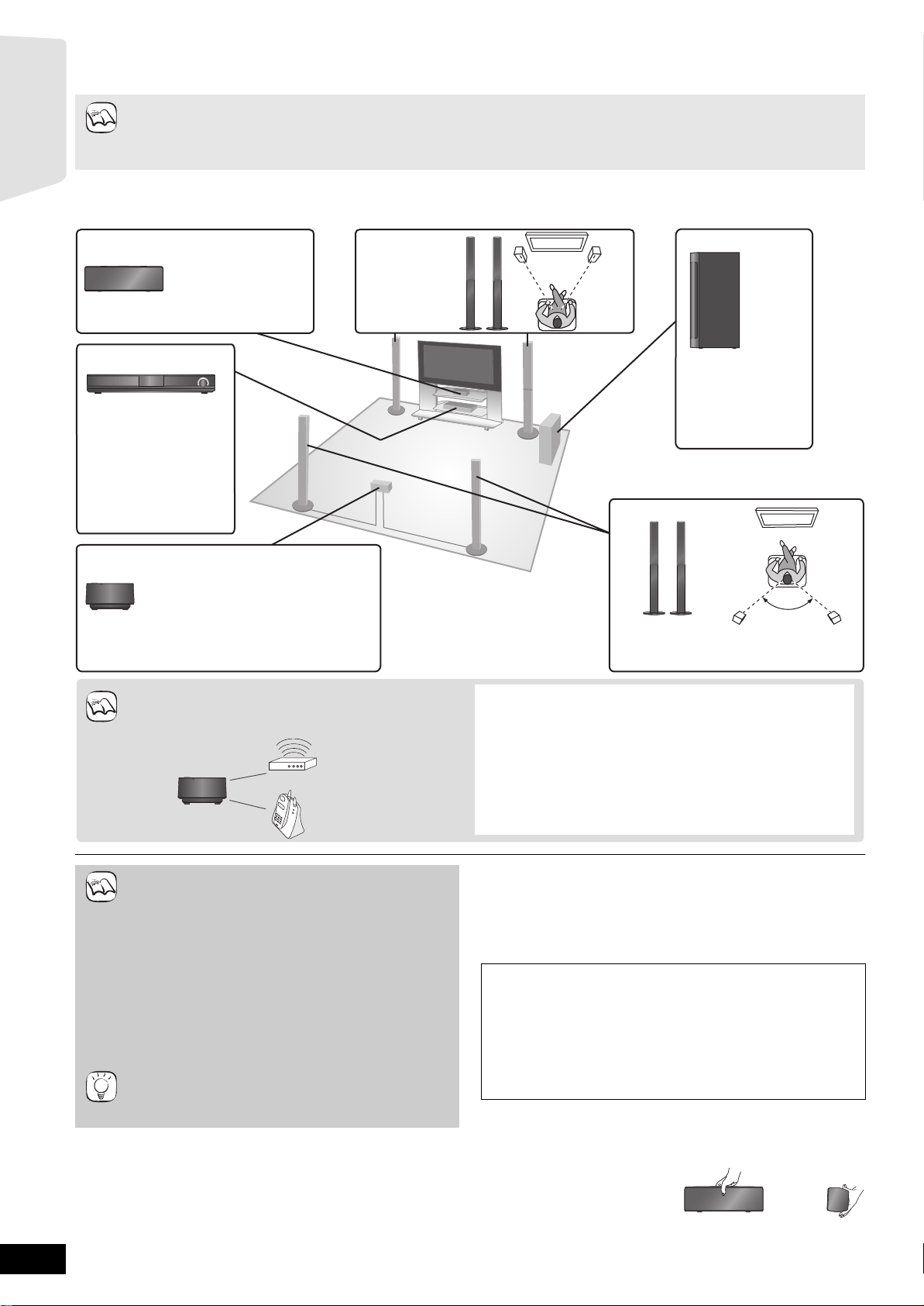
Positioning
Wireless system*
≥Place the wireless system within
approximately 15 m from the main unit,
and in a horizontal position with the top
panel faced upward.
≥To allow for proper ventilation and to
maintain good airflow around the
wireless system, position it with at least
5 cm of space on all sides.
To avoid interference, maintain the following
distances between the wireless system and
other electronic devices that use the same
radio frequency (2.4 GHz band).
The wireless system will automatically seek a clear channel if any
of these other devices interfere with its communication. When this
happens, the wireless link indicator (“ [W1] ”) flashes on the main
unit, and there is a brief interruption in audio coming from the
surround speakers.
This is the normal operation of the product working to assure the
best possible performance of your home theater system.
If the interference persists, try moving the other devices to another
location outside the range of the wireless system or move the
wireless system nearer to the main unit.
Wireless LAN:
approx. 2 m
Cordless phone and
other electronic devices:
approx. 2 m
Wireless
system
* Do not use the wireless system or
the digital transmitter in a metal
cabinet or bookshelf.
How you set up your speakers can affect the bass and the sound field.
≥This system is a 5.1ch sound system.
≥Place speakers on flat secure bases.
≥Placing speakers too close to floors, walls, and corners can result in excessive bass. Cover walls and windows with thick curtains.
NOTE
≥For optional wall mount, refer to page 43.
Getting started
Setup example
Place the front, center, surround speakers at approximately the same distance from the seating position. Using “SMART SETUP” (>15) is a convenient
way to get the ideal surround sound from your speakers when you are unable to place them. The angles in the diagram are approximate.
≥Keep your speakers at least 10 mm away from the system for proper ventilation.
Center speaker
Put on a rack or shelf.
Vibration caused by the
speaker can disrupt the
picture if it is placed
directly on the TV.
Main unit
To allow for proper
ventilation and to
maintain good airflow
around the main
unit, position it with at
least 5 cm of space on
all sides.
Front speakers
Subwoofer
45º to 60º
Place to the right or
left of the TV, on the
floor or a sturdy shelf
so that it will not
cause vibration.
Leave about 30 cm
from the TV.
Surround speakers
120°
Position the speakers as illustrated and
place them at the same height or higher
than ear level.
NOTE
≥Use only supplied speakers
Using other speakers can damage the unit, and sound
NOTE
TIPS
RQT9483
quality will be negatively affected.
≥You can damage your speakers and shorten their useful
life if you play sound at high levels over extended
periods.
≥Reduce the volume in the following cases to avoid
damage:
– When playing distorted sound.
– When the speakers are reverberating due to a record
player, noise from FM broadcasts, or continuous
signals from an oscillator, test disc, or electronic
instrument.
– When adjusting the sound quality.
– When turning the unit on or off.
≥Positioning speakers in front
It is possible to locate all the speakers in front of the
listening position. However the optimal surround sound
effect may not be obtainable.
8
If irregular colouring occurs on your TV
The center speaker is designed to be used close to a TV, but the
picture may be affected with some TVs and setup combinations.
If this occurs, turn the TV off for about 30 minutes.
The demagnetising function of the TV should correct the problem. If it
persists, move the speakers further away from the TV.
Caution
≥The main unit and supplied speakers are to be used only as
indicated in this setup. Failure to do so may lead to damage to
the amplifier and/or the speakers, and may result in the risk of
fire. Consult a qualified service person if damage has
occurred or if you experience a sudden change in
performance.
≥Do not attempt to attach these speakers to walls using
methods other than those described in this manual.
Caution
Do not touch the front netted area of the speakers. Hold by the sides.
e.g. Center speaker
DO
NOT
DO
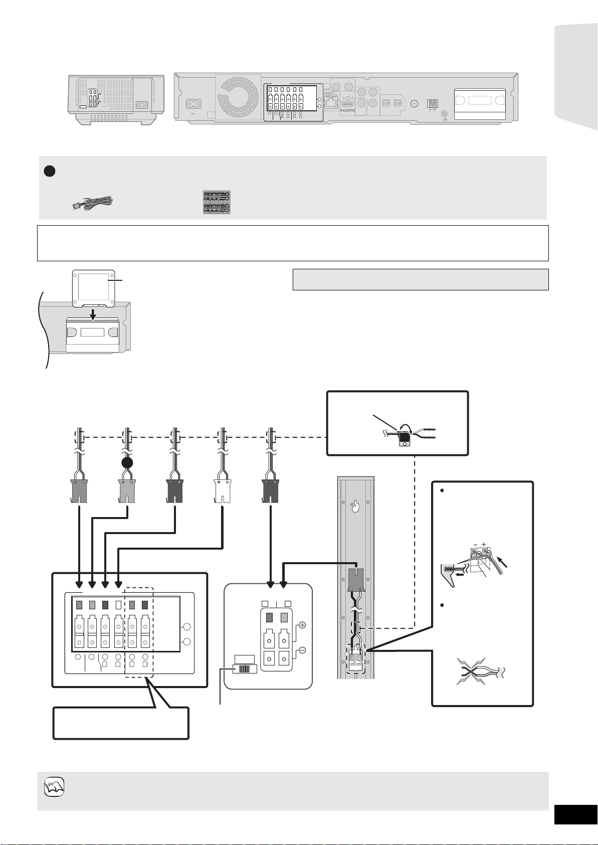
Speaker connections
TRANSMITTER
DIGITAL
Main unit
Surround speaker (R)
Wireless system
Surround selector
1
FRONT
Lch
Push!
e.g. Front speaker (L)
The surround selector switch must be set in the center position.
e.g.
Speaker cable sticker (included)
: White
: Blue
Do not connect the surround
speaker cables to the main unit
when using the wireless system*
1
.
BLUE
SURROUND
(Lch)
GREY
SURROUND
(R
ch)
RED
FRONT
(Rch)
WHITE
FRONT
(Lch)
PURPLE
SUBWOOFER
GREEN
CENTER
Insert the wire fully,
taking care not to insert
beyond the wire
insulation.
Be careful not to cross
(short circuit) or reverse
the polarity of the
speaker wires as doing
so may damage the
speakers.
DO NOT
SPEAKERS
ENCEINTES
LS / RB LB / RS
SURROUND (3 - 6 Ω)
AMBIOPHONIQUES
SURR
L
SIDERSIDE
1
Turn off all equipment before connection and read the appropriate operating instructions.
Do not connect the AC mains lead until all other connections are complete.
AUX(TV )
R
+
-
AV OUT
Setup example
SPEAKERS
AC IN
3
Ω
WOOFER
2
4
1
3
5
6
3Ω3
Ω
3
Ω
SUB-
R
R
L
L
CENTER
FRONT
SURROUND
Main unitWireless system
L
Y
P
B
VIDEO
OUT
P
COMPONENT
VIDEO OUT
R
2(STB) 1(TV)
OPTICAL
DIGITAL IN
FM ANT
LOOP
75Ω
EXT
ANT
AM
GNDANTLOOP
DIGITAL
TRANSMITTER
Getting started
Speaker cable for center
1
speaker (Green)
≥Don’t use a front speaker as a surround speaker or vice versa. Verify the type of speaker with label on the rear label of the speaker
before connecting the appropriate cable.
Sheet of speaker cable
stickers
≥Pay attention to the type of speaker and the connector colour when you place the speakers.
Do not insert or remove the digital transmitter while the main
unit is on.
DIGITAL
TRANSMITTER
Digital transmitter
Insert fully until you hear a click.
Main unit
SPEAKERS
+
-
6
3
Ω
SUBWOOFER
5
3Ω3
CENTER
2
Ω
R
FRONT
1
R
L
SURROUND
3
3
Ω
L
4
Connect to the terminals of the same colour.
Use of the speaker cable stickers is convenient when making cable connections.
≥Match the connector colour and the type of speaker as shown above.
≥Extending the speaker cables may damage the speakers and sound quality will negatively be affected.
NOTE
*1 Disconnect the surround speaker cables from the wireless system and connect them to the main unit if you do not want to use the
wireless system.
RQT9483
9
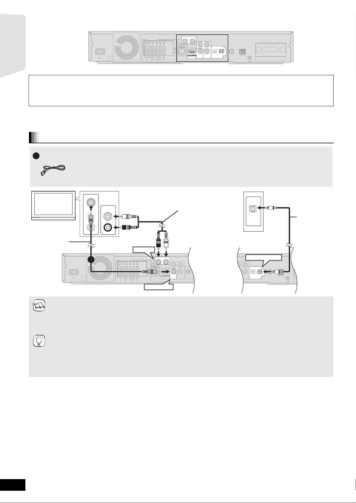
TV connections
COMPONENT
VIDEO OUT
PR
PB
VIDEO
OUT
OPTICAL
2(STB) 1(TV)
DIGITAL IN
OPTICAL
2(STB) 1(T
DIGITAL IN
COMPONENT
VIDEO OUT
Y
P
R
PB
SPEAKERS
-
AV OUT
R
L
CENTER
3Ω3
Ω
FRONT
6
5
2
1
R
L
3
Ω
SURROUND
4
3
AC IN
VIDEO
OUT
+
WOOFER
3
Ω
SUB-
L
R
AUX(TV)
ANT
EXT
LOOP
AM
GNDANTLOOP
FM ANT
75Ω
L
R
AUDIO OUT
L
VIDEO IN
R
AUDIO IN
OPTICAL
OUT
VIDEO OUT
AUX(TV)
OPTICAL 1(TV)
Optical digital
audio cable*
1,2
(not included)
TV
Audio cable*
1
(not included)
The optical digital audio
cable can be used when
connecting to televisions
with optical out terminals
( right).
Main unit
Video cable
(included)
1
AUX(TV)
R
AV OUT
AV OUT
L
Y
PB
Y
PB
Y
PB
OPTICAL
OPTICAL
P
P
P
R
R
R
2(STB) 1(TV)
2(STB) 1(TV)
COMPONENT
COMPONENT
COMPONENT
VIDEO
VIDEO
VIDEO
OUT
OUT
OUT
VIDEO OUT
VIDEO OUT
VIDEO OUT
DIGITAL IN
DIGITAL IN
FM ANT
75Ω
SPEAKERS
+
Getting started
AC IN
3
Ω
SUB-
WOOFER
2
1
6
5
3Ω3
Ω
R
L
CENTER
FRONT
4
3
Ω
R
SURROUND
-
3
L
Main unit
My television has COMPONENT VIDEO IN terminals and HDMI IN terminal. Which should I connect with?
≥The different levels of picture quality input are listed below in order from highest to lowest.
HDMI IN )COMPONENT VIDEO IN )VIDEO IN. However, it will take longer for the picture output to start up when this unit is connected with
the HDMI IN terminal.
– To enjoy all features of this unit, connect the video cable, even if the component video cable or the HDMI cable is used.
For connections with a video cable (> below)
For connections with a component video cable (> 11)
For connections with a HDMI cable (> 11)
Connections with a video cable
Video cable
1
DIGITAL
TRANSMITTER
LOOP
EXT
ANT
AM
GNDANTLOOP
RQT9483
10
NOTE
TIPS
≥Set “High Clarity Sound” on the on-screen menu to “Off” (> 37).
(Otherwise, the video will not be output.)
Optional connections
≥For those who want to enjoy higher picture quality and have a TV equipped with an HDMI terminal (> 11 )
≥For those who want to enjoy higher picture quality and have a TV equipped with a COMPONENT VIDEO IN terminal (> 11)
≥For those who have a Set Top Box (Satellite receiver, Cable box, etc.) or video cassette recorder (> 12)
To enjoy TV audio from this home theater system’s speakers
*1 You can enjoy the audio from your TV through this home theater system’s speakers by connecting to the “AUX(TV)” terminal or
“OPTICAL 1(TV)” terminal. (> 28)
*2 This is the preferred connection for best sound and true surround sound depending on your television.
This unit can decode the surround signals received from your TV. Refer to the operating instructions for the TV for the settings
necessary to output its audio from the digital audio output to your home theater system. Only Dolby Digital and PCM can be played
with this connection.
– After making this connection, make settings to suit the type of audio from your digital equipment (> 28).
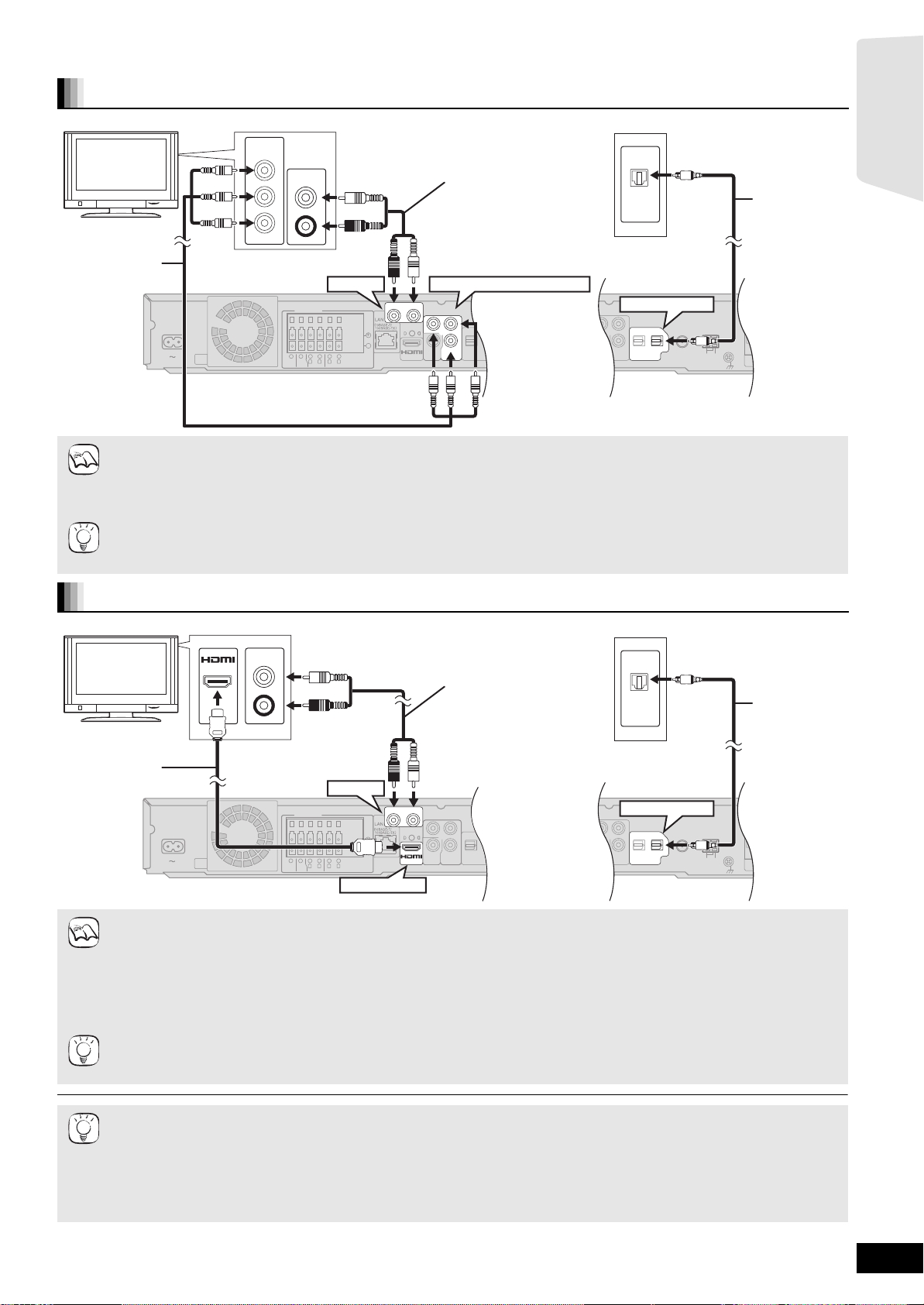
Connections with a component video cable
OPTICAL
2(STB) 1(T
DIGITAL IN
COMPONENT
VIDEO OUT
Y
P
R
P
B
SPEAKERS
+
-
AV OUT
R
L
CENTER
3Ω3
Ω
FRONT
6
5
2
1
R
L
3
Ω
SURROUND
4
3
AC IN
VIDEO
OUT
COMPONENT
VIDEO OUT
Y
P
R
P
B
VIDEO
OUT
COMPONENT
VIDEO OUT
P
R
P
B
VIDEO
OUT
OPTICAL
2(STB) 1(TV)
DIGITAL IN
COMPONENT
VIDEO OUT
P
R
P
B
VIDEO
OUT
OPTICAL
2(STB) 1(TV)
DIGITAL IN
OPTICAL
2(STB) 1(T
DIGITAL IN
COMPONENT
VIDEO OUT
Y
P
R
P
B
SPEAKERS
+
-
R
L
CENTER
3Ω3
Ω
FRONT
6
5
2
1
R
L
3
Ω
SURROUND
4
3
AC IN
VIDEO
OUT
AV OUT
COMPONENT
VIDEO OUT
Y
P
R
P
B
VIDEO
OUT
Do not disconnect the video cable even if the below is connected. Some features may not be displayed.
COMPONENT
Component
Video cable
(not included)
Main unit
NOTE
TIPS
TV
VIDEO IN
Y
PB
P
R
3
Ω
WOOFER
AUDIO OUT
SUB-
L
R
AUX(TV)
AUX(TV)
R
Audio cable*
(not included)
The optical digital audio
cable can be used when
connecting to televisions
with optical out terminals
( right).
COMPONENT VIDEO OUT
L
≥Connect to terminals of the same colour.
≥Set “High Clarity Sound” on the on-screen menu to “Off” (> 37).
(Otherwise, the video will not be output.)
≥The video output resolution is restricted to “576p/480p” when DVD-Video discs, DivX and BD-Video discs recorded at a rate of 50
field per second are output from the COMPONENT VIDEO OUT terminals.
To enjoy high definition/progressive video
≥Connect to a television that supports 576p/480p or higher.
≥Set “Component Resolution” to “576p/480p”, “720p” or “1080i”. (> 40)
≥Set “HDMI Video Mode” to “Off”. (> 40) Otherwise, the video is output as 480i.
1
OPTICAL
OUT
OPTICAL 1(TV)
FM ANT
Getting started
Optical digital
audio cable*
(not included)
LOOP
75Ω
EXT
ANT
AM
GNDANTLOOP
1,2
Connections with a HDMI cable
Do not disconnect the video cable even if the below is connected. Some features may not be displayed.
compatible
HDMI cable
(not included)
Main unit
NOTE
TIPS
HDMI
TV
AV IN
AUDIO OUT
L
R
Audio cable*
(not included)
The optical digital audio
cable can be used when
connecting to televisions
with optical out terminals
( right).
AUX(TV)
AUX(TV)
R
L
3
Ω
SUB-
WOOFER
HDMI AV OUT
≥If there is more than one HDMI terminal, refer to the operating instructions for the TV to determine terminal to connect to.
≥Non-HDMI-compliant cables cannot be utilized.
≥Please use High Speed HDMI Cables that have the HDMI logo (as shown on the cover). It is recommended that you use
Panasonic’s HDMI cable.
Recommended part number:
RP-CDHG10 (1.0 m), RP-CDHG15 (1.5 m), RP-CDHG20 (2.0 m), RP-CDHG30 (3.0 m), RP-CDHG50 (5.0 m), etc.
≥This unit incorporates HDMI
TM
(V.1.3a with Deep Colour, x.v.ColourTM, High Bit rate Audio) technology. (> 55, 56)
≥When outputting 1080p signal (> 40,“HDMI Video Format”), please use HDMI cables 5.0 meters or less.
NECESSARY SETTINGS
“HDMI Video Mode” : “On”/“HDMI Audio Output” : “Off” (> 40)
With this connection, you can use VIERA Link “HDAVI Control” (> 29).
1
OPTICAL
OUT
OPTICAL 1(TV)
FM ANT
Optical digital
audio cable*
1,2
(not included)
LOOP
75Ω
EXT
ANT
AM
GNDANTLOOP
To enjoy TV audio from this home theater system’s speakers
*1 You can enjoy the audio from your TV through this home theater system’s speakers by connecting to the “AUX(TV)” terminal or
TIPS
“OPTICAL 1(TV)” terminal. (> 28)
*2 This is the preferred connection for best sound and true surround sound.
This unit can decode the surround signals received from your TV. Refer to the operating instructions for the TV for the settings
necessary to output its audio from the digital audio output to your home theater system. Only Dolby Digital and PCM can be played
with this connection.
– After making this connection, make settings to suit the type of audio from your digital equipment (> 28).
RQT9483
11
Connections to a Set Top Box, etc.
A
Use the following connections when you want to output the original surround audio from your Set Top Box, cable TV, VCR, DVD recorder, etc.
through this unit’s speakers.
≥Do not connect through the video cassette recorder.
Due to copy guard protection, the picture may not be displayed properly.
≥Turn off all equipment before connection.
Getting started
STB, VCR, DVD recorder, etc.
TV
OPTICAL
OUT
Refer to the operating instructions of the respective devices
for the optimal connections.
AC IN
3
Ω
SUB-
WOOFER
6
SPEAKERS
5
3Ω3
CENTER
AUX(TV)
R
+
4
3
Ω
R
SURROUND
-
3
L
AV OUT
2
1
Ω
R
L
FRONT
OPTICAL 2(STB)
L
Y
P
B
P
R
COMPONENT
VIDEO
OUT
VIDEO OUT
OPTICAL
2(STB) 1(TV)
DIGITAL IN
FM ANT
DIGITAL
TRANSMITTER
LOOP
75Ω
EXT
ANT
AM
GNDANTLOOP
Main unit
≥This unit can decode the surround signal from the Set Top Box (Satellite receiver, Cable box, etc).
“
Press [EXT-IN] several times to select
* “(CABLE/SAT)” is displayed next to DIGITAL IN 2 when set for CABLE/SAT AUDIO input. (> 29, Setting the TV audio for VIERA
TIPS
Link “HDAVI Control”)
D-IN 2” (DIGITAL IN 2*).
≥For connections between this unit and the TV, refer to “TV connections” (> 10, 11).
≥If you have various sound sources and this unit’s terminals are not sufficient, connect them to the available inputs on the TV and the
TV output should then be connected to the “AUX(TV)” or “OPTICAL 1(TV)” terminal of the main unit.
Refer to the operating instructions of the TV, video cassette recorder, DVD recorder or Set Top Box for settings to output its audio via
AUDIO OUT or OPTICAL OUT terminal of the TV.
– In some cases the audio signal will only be out as 2ch audio from the TV. In this case, connect the Set Top Box (Satellite receiver,
Cable box, etc.) that will be used most commonly with multi-channel audio to this unit’s “OPTICAL 2(STB)” terminal.
Optical digital
audio cable
(not included)
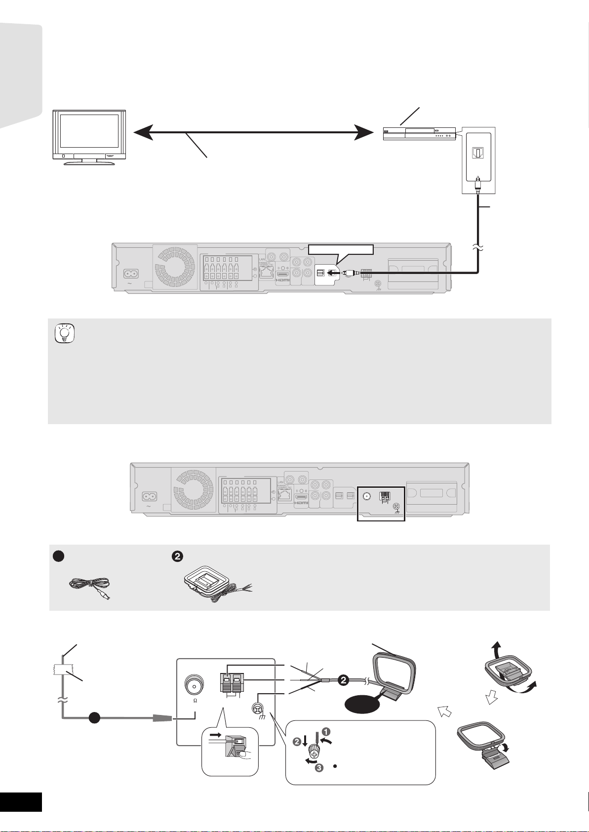
Radio antenna connections
AUX(TV)
R
SPEAKERS
+
AC IN
3
Ω
SUB-
WOOFER
2
1
6
5
3Ω3
Ω
R
L
CENTER
FRONT
4
3
Ω
R
SURROUND
-
3
L
Main unit
≥Keep loose antenna cables away from other wires and cables.
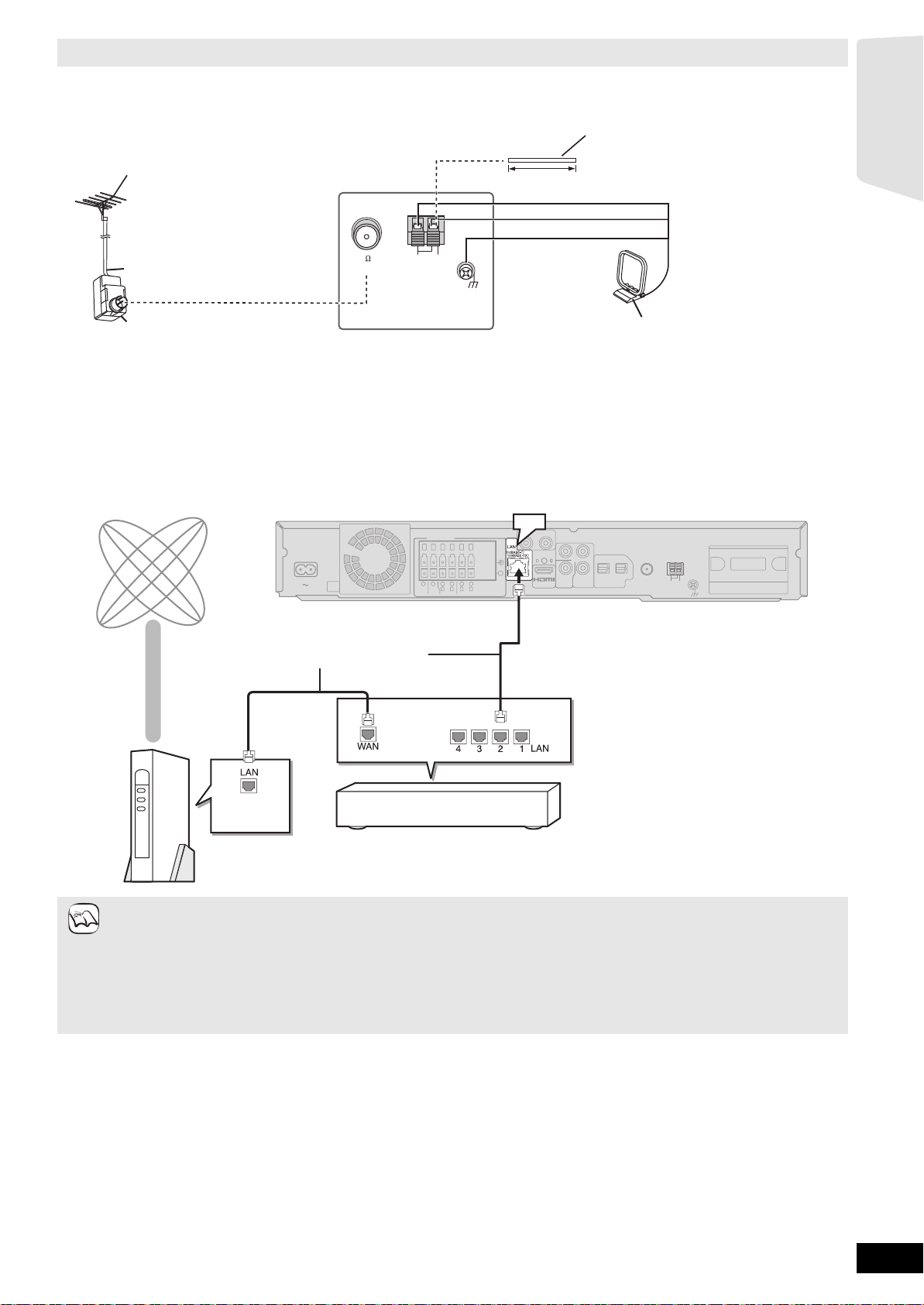
FM Indoor antenna
1
AM loop antenna
FM indoor antenna (included)
ffix this end of the antenna
where reception is best.
Adhesive
tape
75
1
LOOP
AM ANTFM ANT
LOOP ANT GND
EXT
Main unit
Push!
L
Y
PB
AV OUT
VIDEO
OUT
P
COMPONENT
VIDEO OUT
R
2(STB) 1(TV)
DIGITAL IN
OPTICAL
FM ANT
LOOP
75Ω
EXT
ANT
AM
GNDANTLOOP
DIGITAL
TRANSMITTER
AM loop antenna (included)
Stand the antenna up on its base.
Place the antenna where reception is best.
White
Red
Black
Click!
Use a Phillips-head
screwdriver, etc.
(not included)
Do not screw too tightly.
RQT9483
12
Using an FM/AM outdoor antenna (optional)
Use outdoor antenna if FM/AM radio reception is poor.
≥Disconnect the antenna when the unit is not in use.
≥Do not use the outdoor antenna during an electrical storm.
FM outdoor antenna
[Using a TV antenna (not included)]
The antenna should be installed by a
competent technician.
5 m to 12 m
AM outdoor antenna
[Using a vinyl wire (not included)]
Run a piece of vinyl wire horizontally
across a window or other convenient
location.
Getting started
75 coaxial cable*
(not included)
Antenna plug (not included)
75
EXTLOOP
AM ANTFM ANT
LOOP ANT GND
Main unit
Network connection
The following services can be used when this unit is connected to the internet via a broadband.
≥Firmware can be updated (> 33)
≥You can enjoy the BD-Live (> 22)
≥You can enjoy the VIERA CAST (> 33)
Internet
AC IN
Main unit
Straight LAN cable (not included)
6
3
Ω
SUB-
WOOFER
SPEAKERS
5
3Ω3
CENTER
2
4
1
3
Ω
3
Ω
R
R
L
L
FRONT
SURROUND
LAN
AUX(TV)
R
L
AV OUT
AV OUT
Y
VIDEO
VIDEO
+
-
Leave the AM loop
antenna connected.
PB
OPTICAL
P
R
2(STB) 1(TV)
COMPONENT
OUT
OUT
VIDEO OUT
DIGITAL IN
FM ANT
DIGITAL
TRANSMITTER
LOOP
75Ω
EXT
ANT
AM
GNDANTLOOP
NOTE
Hub or broadband router
Telecommunications equipment
(modem, etc.)
≥When your communication equipment (modem), etc. has no broadband router functions: Connect a broadband router.
When your communication equipment (modem), etc. has broadband router functions but there are no vacant ports: Connect a hub.
≥Use shielded LAN cables when connecting to peripheral devices.
≥Use a router that supports 10BASE-T/100BASE-TX.
≥When operating the VIERA CAST, use high-speed internet service no less than 1.5 Mbps for SD (Standard Definition) and 6 Mbps
for HD (High Definition) picture quality by your local broadband company.
– If using slow Internet connection, the video may not be displayed correctly.
≥Depending on a contract with your local broadband company, it may be generating communication charges.
≥After connecting to the Internet, perform necessary settings. (> 34)
≥Inserting any cable other than a LAN cable in the LAN terminal can damage the unit.
RQT9483
13
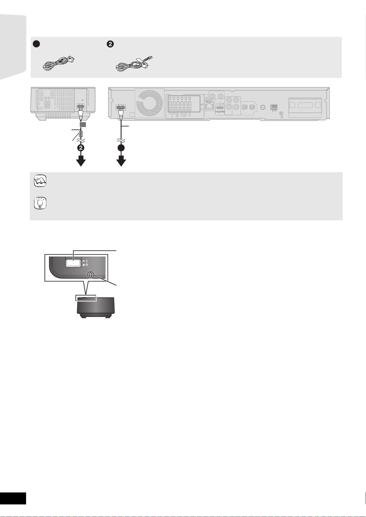
AC mains lead connection
WIRELESS LINK indicator
Red: The wireless system is on and the wireless link is deactivated.
Green: The wireless system is on and the wireless link is activated.
(“ [W1] ” is also displayed on the main unit’s display.)
Press [C I, BÍ] on the wireless system.
Unit on/off button [C I, BÍ]
Use this button to turn the wireless system on and off.
C I: The wireless system is on.
BÍ: The wireless system is off.
Wireless system
≥Before turning the power on for the first time, be sure to read the preparations for SMART SETUP. (> 15)
Getting started
AC mains lead
1
(for the main unit)
AC mains lead
(included)
Ferrite core
To a household
mains socket
Connect only after all other connections are complete.
NOTE
Conserving power
This unit consumes a small amount of power even when it is turned off (main unit: approx. 0.3 W, wireless system: approx. 0.3 W). To
save power when the unit is not to be used for a long time, unplug it from the household mains socket.
TIPS
You will need to reset some memory items after plugging in the main unit.
AC mains lead
(for the wireless system)
Main unitWireless system
AUX(TV)
R
3
Ω
SUB-
WOOFER
6
SPEAKERS
5
3Ω3
CENTER
2
R
FRONT
+
-
4
1
3
Ω
3
Ω
R
L
L
SURROUND
AC IN
AC IN
AV OUT
L
Y
PB
Y
PB
VIDEO
VIDEO
OUT
OUT
P
P
COMPONENT
COMPONENT
VIDEO OUT
VIDEO OUT
R
R
2(STB) 1(TV)
DIGITAL IN
OPTICAL
FM ANT
LOOP
75Ω
EXT
ANT
AM
GNDANTLOOP
DIGITAL
TRANSMITTER
AC mains lead (included)
1
To a household mains socket
Preparing the wireless system
Turn on the wireless system after all connections are complete.
WIRELESS LINK
RQT9483
14
SMART SETUP
RETURN
OK
BD/SD
RETURN
BD/SD
OK
The SMART SETUP screen assists you to make necessary
settings.
When the system is switched on for the first time, the SMART SETUP
screen for the basic settings is displayed automatically. Follow the
on-screen prompts to make basic settings for the system.
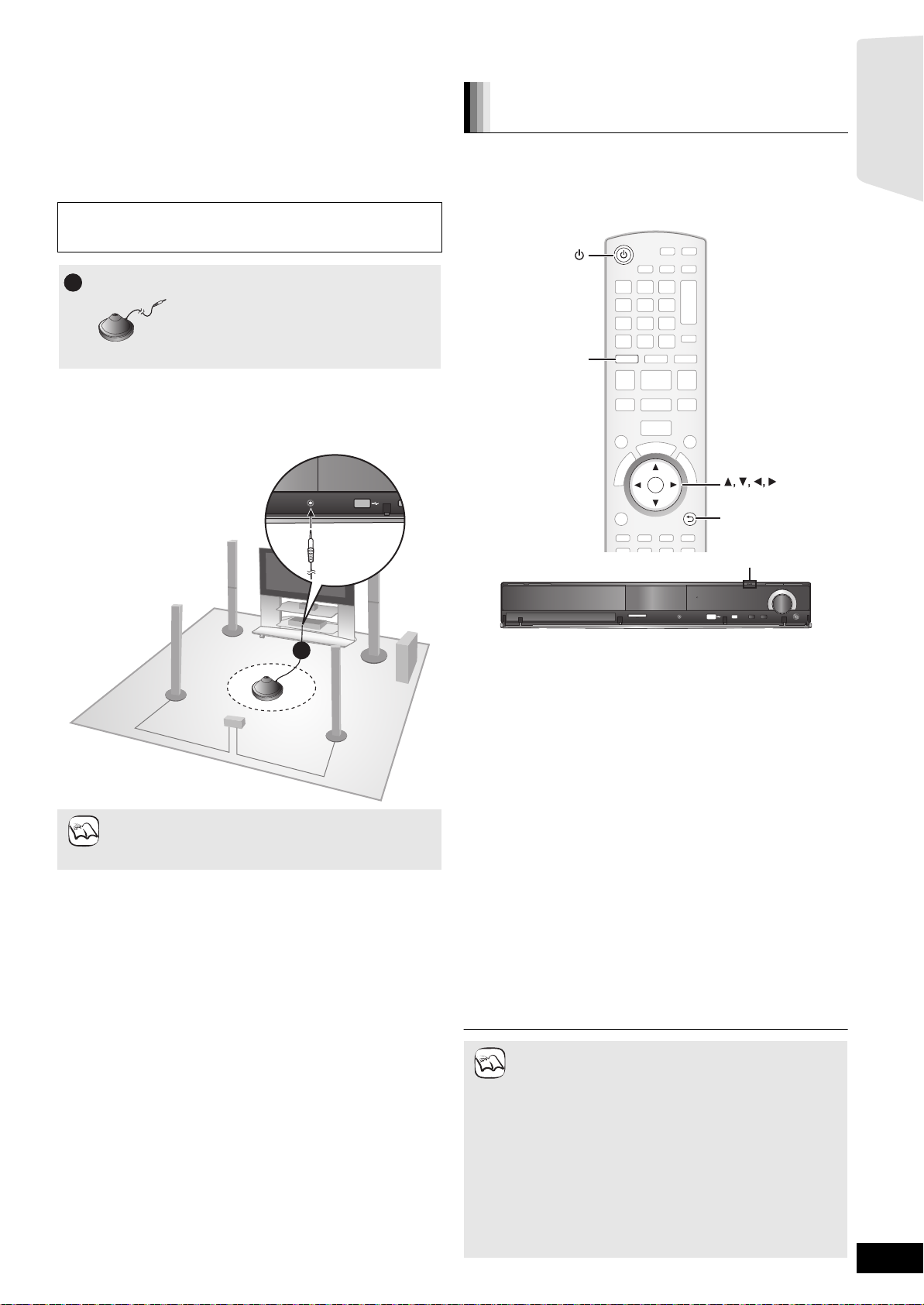
Preparation
To optimize the surround sound experience we recommend that you
setup the speaker output level using the Auto speaker setup function.
Keep as quiet as possible during the Auto speaker setup. Excessive
background noise may lead to incorrect settings. The speakers
output loud test signals during setup.
Auto speaker setup microphone
1
≥Place the Auto speaker setup microphone at actual seating position.
(At ear level when seated.)
≥A test signal is output from each speaker during the SMART SETUP.
≥After the SMART SETUP is completed, unplug the Auto speaker setup
microphone and keep it for future use.
Basic setting for the system
(SMART SETUP)
Preparation
Turn on your TV and select the appropriate video input mode (e.g.
VIDEO 1, AV 1, HDMI, etc.) to suit the connections to this unit.
≥To change your TV’s video input mode, refer to its operating
instructions.
≥This remote control can perform some basic TV operations (> 5).
Getting started
NOTE
1
≥Auto Speaker Setup can be activated through SMART
SETUP only.
≥Audio settings will be restored to default if Auto Speaker
Setup is cancelled.
SMART SETUP
SD CARD
SD CARD
TUNE
SELECTORSETUP MIC
TUNE
SELECTORSETUP MIC
TUNE
SELECTOR
SELECTOR
1 Press [Í].
≥When the SMART SETUP screen appears automatically, skip
step 2 and 3.
2 Press [BD/SD] to select “BD/DVD”.
3 Press [SMART SETUP] on the main unit.
≥The SMART SETUP screen appears.
4 Follow the on-screen instructions and make the
settings with [3, 4, 2, 1] and [OK].
≥Language (> below)
Select the language used on menu screen.
≥TV Aspect (> below)
Select the aspect to suit your TV and preference.
≥Speakers position
Specify the positioning of the surround speakers.
≥Auto Speaker Setup
Adjust the speaker output level automatically.
≥Speaker Output
Make surround sound setting for speaker output.
≥TV Audio
Select the audio input connection from your TV.
For AUX connection (> 10): Select “AUX”.
For OPTICAL DIGITAL IN connection (> 10): Select “DIGITAL
IN 1”.
This will be the TV Audio setting for VIERA Link “HDAVI
Control”. (> 29)
To return to the previous screen, press [RETURN].
5 Press [OK] to finish the SMART SETUP.
≥If this unit is connected to a “HDAVI Control 3 (or later)”
compatible TV via HDMI cable, the menu language and
NOTE
TV aspect information will be retrieved via VIERA Link.
≥If this unit is connected to a “HDAVI Control 2” compatible
TV via HDMI cable, the menu language information will
be retrieved via VIERA Link.
≥Even if this unit is connected to a “HDAVI Control 2 (or
later)” compatible TV via HDMI cable, the menu screen
language will not be automatically retrieved if this unit
does not support the language. In this case, set the
language manually.
≥Settings in the SMART SETUP can also be changed in
the unit settings [e.g. language, TV aspect and speaker
level (> 38)].
≥Positioning examples for mounting all speakers in front.
(> 8)
RQT9483
15
e.g., [BD-V]
e.g., [BD-V]
Getting started
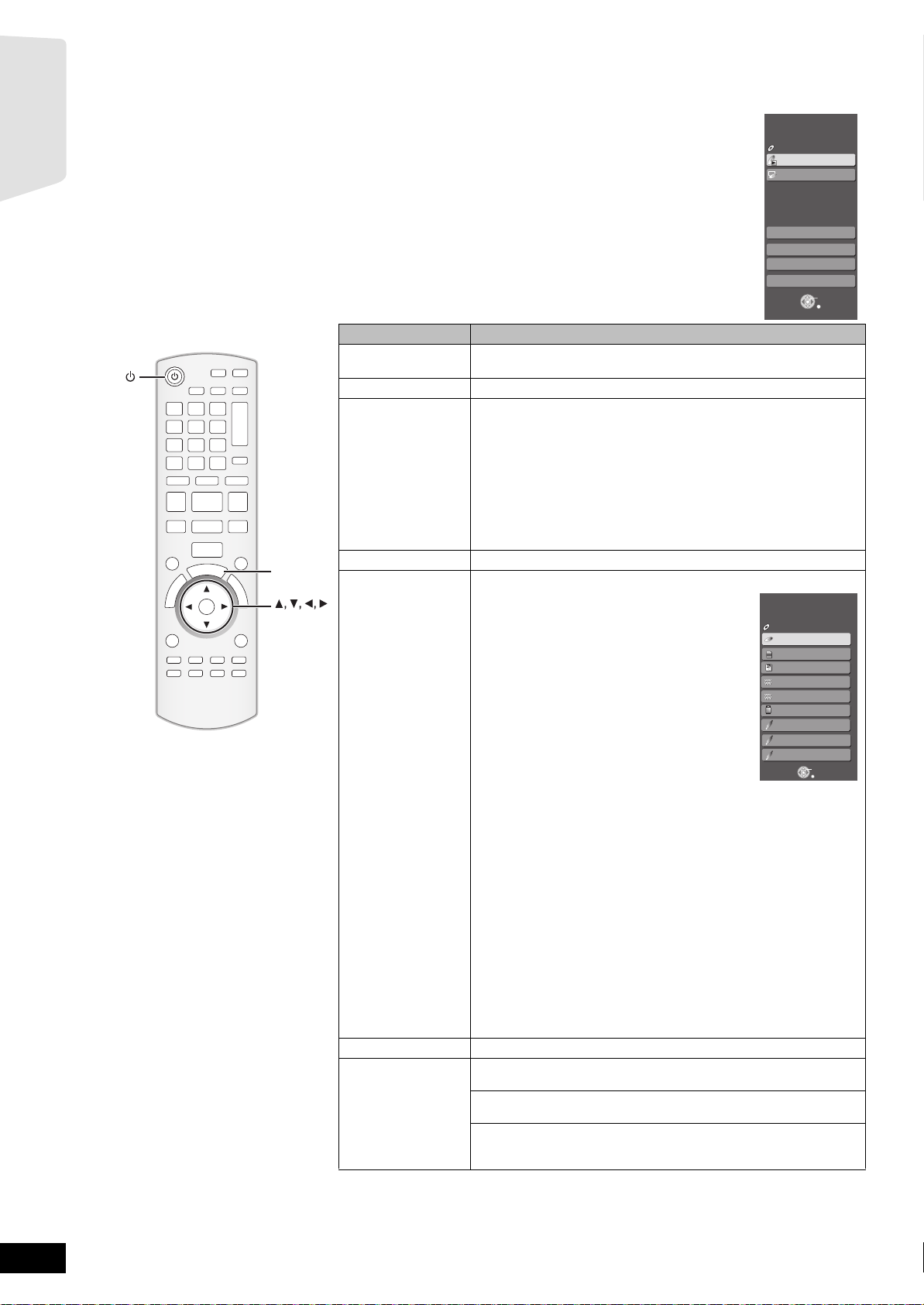
Showing START menu
Some functions of this unit can be operated from the START menu.
1 Press [Í] to turn on the unit.
2 Press [START].
≥Items displayed vary according to the chosen selector and
media.
3 Press [3, 4] to select
Items Functions
Playback Disc
Playback
Top M e n u
Menu
R
A
T
T
S
OK
START
OK
Network
Input Selection
Sound(Equalizer)
To Ot h e r s Setup:
Home Cinema
BD-Video
the item and pr
ess [OK].
Playback Disc
Top Menu
Menu
Network
Input Selection
Sound(Equalizer)
To Others
Starts playing disc/USB device/SD Card.
Shows a disc top menu.
Shows a media menu.
To play AVCHD (> 21)
To play MPEG2 (> 21)
To play MP3, CD (> 26)
To play JPEG (> 24)
To play DivX (> 23)
Shows the iPod menu.
To play “Music” (> 32)
To play “Videos” (> 32)
To play “Use iPod display (All)” (> 32)
For “Play Mode ” (> 32)
Displays Home screen of VIERA CAST (> 33)
Select the source.
BD/DVD/CD:
To play BD-Video, DVD-Video, AVCHD (> 19-22)
To play JPEG (> 24)
To play DivX (> 23)
To play MP3, CD (> 26)
SD card:
To play AVCHD (> 21)
To play MPEG2 (> 21)
To play JPEG (> 24)
iPod:
To play iPod contents (> 32)
FM:
Home Cinema
Input Selection
BD-Video
BD/DVD/CD
SD
SD card
iPod
FM
AM
USB device
AUX (TV)
DIGITAL IN 1
DIGITAL IN 2
To enjoy the FM radio (> 27)
AM:
To enjoy the AM radio (> 27)
USB device:
To play MP3 (> 26)
To play JPEG (> 24)
To play DivX (> 23)
AUX (TV)*1:
To enjoy TV broadcasts with this unit’s speakers (> 28)
DIGITAL IN 1 (TV)*1:
To enjoy TV broadcasts with this unit’s speakers (> 28)
DIGITAL IN 2 (CABLE/SAT)*2:
To enjoy audio from other devices with this unit’s speakers (> 28)
1
“(TV)” is displayed next to items set for TV AUDIO input. (B 29,
*
Setting the TV audio for VIERA Link “HDAVI Control”)
2
“(CABLE/SAT)” is displayed next to DIGITAL IN 2 when set for
*
CABLE/SAT AUDIO input. (> 29, Setting the TV audio for VIERA
Link “HDAVI Control”)
Select the equalizer function (> 18)
You can change the unit’s settings using Setup menu (> 38).
Card Management:
Formatting SD cards/Deleting data (> 22)
Playlists:
You can play playlists created on DVD-VR.
Press [3, 4, 2, 1] to select the playlist and press [OK].
START
OK
RETURN
START
OK
RETURN
RQT9483
16
Selecting the playback source
OK
BD/SD
iPod
EXT-IN
RADIO
S
T
A
R
T
SELECTOR
OK
RADIO/EXT-INBD/SD
iPod
START
TUNE
SELECTORSETUP MIC
SD CARD
TUNE
SELECTOR
TUNE
SELECTORSETUP MIC
SD CARD
SELECTOR
Selecting the source from the START menu
You can select sound modes, desired source, or access playback/menus by using
the START menu.
1 Press [Í] to turn on the unit.
2 Press [START] to show the START menu.
3 Press [3, 4] to select the item and then
press [OK].
≥To exit, press [START].
4 Press [3, 4] to make the setting.
When “Input Selection” is selected
You can select a desired source from the menu.
≥BD/DVD/CD, SD card, iPod, FM, AM, USB device, AUX
DIGITAL IN 1
*1 “(TV)” is displayed next to items set for TV AUDIO input.
(> 29, Setting the TV audio for VIERA Link “HDAVI Control”)
*2 “(CABLE/SAT)” is displayed next to DIGITAL IN 2 when set
for CABLE/SAT AUDIO input. (> 29, Setting the TV audio for
VIERA Link “HDAVI Control”)
When a disc is loaded, an USB device is connected or a SD card is inserted, you
can also access playback or menus from the START menu.
*1
, DIGITAL IN 2*2 (> 16)
*1
,
e.g. [BD-V]
Playback/menu access
Home Cinema
No Disc
Network
Input Selection
Sound(Equalizer)
To Others
Home Cinema
BD-Video
Playback Disc
Top Menu
Menu
Getting started
START
OK
RETURN
START
Network
Input Selection
Sound(Equalizer)
To Others
OK
RETURN
Selecting the source by the remote control
Press To select
BD/SD
iPod
RADIO
EXT-IN
Press [SELECTOR] on the main unit to select source from the main unit.
≥Confirm the audio connection to the AUX or OPTICAL DIGITAL IN
NOTE
≥Reduce the volume on the TV to its minimum, and then adjust the
BD/DVD/CD or SD (> 19)
IPOD (iPod) (> 31)
Each time you press the button:
FM (> 27)
AM (> 27)
USB (> 19)
AUX*1: For audio input through the AUX terminal.(> 28)
D-IN1 (DIGITAL IN 1*
1
): (> 28)
D-IN2 (DIGITAL IN 2*2): (> 28)
*1 “(TV)” is displayed next to items set for TV AUDIO input.
(> 29, Setting the TV audio for VIERA Link “HDAVI Control”)
*2 “(CABLE/SAT)” is displayed next to DIGITAL IN 2 when set for
CABLE/SAT AUDIO input. (> 29, Setting the TV audio for
VIERA Link “HDAVI Control”)
terminals on the main unit when you select the corresponding sources
(> 10 to 12).
volume of the main unit.
RQT9483
17
Enjoying sound from all speakers and
various sound effects
≥The following sound effects/modes may not be available or have no effect with some sources, or when headphones are used (> 19).
≥You may experience a reduction in sound quality when these sound effects/modes are used with some sources. If this occurs, turn the sound
effects/modes off.
Getting started
SURROUND
-
CH SELECT
SURROUND
-
CH SELECT
SOUND
SOUND
OK
Enjoying surround sound effects
Available surround sound effects
Effect Setting
STANDARD: Sound is output as it was recorded/encoded.
MULTI-CH: You can enjoy sound from the front speakers, as well
MANUAL: –DOLBY PL II MOVIE:
Press [SURROUND] several times to select the effect.
≥You can also press [SURROUND] and then [3, 4] to select the
mode.
≥The selected effect will only be displayed on the main unit.
When selecting the MANUAL effects.
While “MANUAL” is displayed
Press [2, 1] and select the desired effect.
≥“NOT CONDITIONAL” is displayed on the main unit if the setting is
not active.
≥“DOLBY PL II MOVIE” and “DOLBY PL II MUSIC” do not work when
audio is output from the HDMI AV OUT terminal.
Speaker output varies depending on the source.
as the surround speakers even when playing a
2-channel sound or non-surround sound.
Suitable for movie software, or the one recorded in
Dolby Surround. (except [DivX])
– DOLBY PL II MUSIC:
Adds 5.1-channel effects to stereo sources.
(except [DivX])
– S.SURROUND:
You can enjoy sound from all speakers with stereo
sources.
– 2CH STEREO:
You can play any source in stereo. Sound will be
output to the front speakers and the subwoofer
only.
Changing the sound modes
Available sound modes
Mode Setting
EQ:
(Equalizer)
SUB W:
(Subwoofer
level)
CF:
(Center
Focus)
W.S.:
(Whispermode
Surround)
You can select sound quality settings.
– FLAT(Flat): Cancel (no effect is added).
– HEAVY(Heavy): Adds punch to rock.
– CLEAR(Clear): Clarifies higher sounds.
– SOFT(Soft): For background music.
This unit will change the settings for the amount of
bass depending on the source.
However you can also adjust the amount of bass for
the source being played.
– 1 (Weakest effect)
–2
–3
– 4 (Strongest effect)
≥The setting you make is retained, and recalled
every time you play the same type of source.
(Effective when playing audio containing center
channel sound.)
You can make the sound of the center speaker seem
like it is coming from within the TV.
–ON
–OFF
(Effective when playing video with 5.1ch audio.)
You can enhance the surround effect for low volume
5.1-channel sound.
(Convenient for late night viewing.)
–ON
–OFF
1 Press [SOUND] several times to select the mode.
≥You can also press [SOUND] and then [3, 4] to select the
mode.
≥The selected effect will only be displayed on the main unit.
2 While the selected mode is displayed
Press [2, 1] and select the desired setting.
Adjusting speaker level during play
1 Press and hold [-CH SELECT] for 3 seconds to
activate the speaker setting mode.
2 Press [-CH SELECT] several times to select the
speaker.
Each time you press the button:
LR—) C_) RS_) LS_) SW
^"""""""""""""""""""b
L R: Front speaker (left and right)
C: Center speaker
RS: Surround speaker (right)
LS: Surround speaker (left)
SW: Subwoofer
≥The channels not included in the playing audio will not be
displayed (subwoofer is displayed even if it is not included).
Adjusting the balance of the front speakers
(When “L R” selected)
3 Press [2, 1] to adjust the balance of the front
speakers.
Adjusting the speaker level
(When other speakers are selected)
4 Press [3] (increase) or [4] (decrease) to adjust
the speaker level for each speaker.
s6 dB to r6 dB
RQT9483
18
 Loading...