

Panasonic SC-AK95, SAAK95 Owner’s Manual
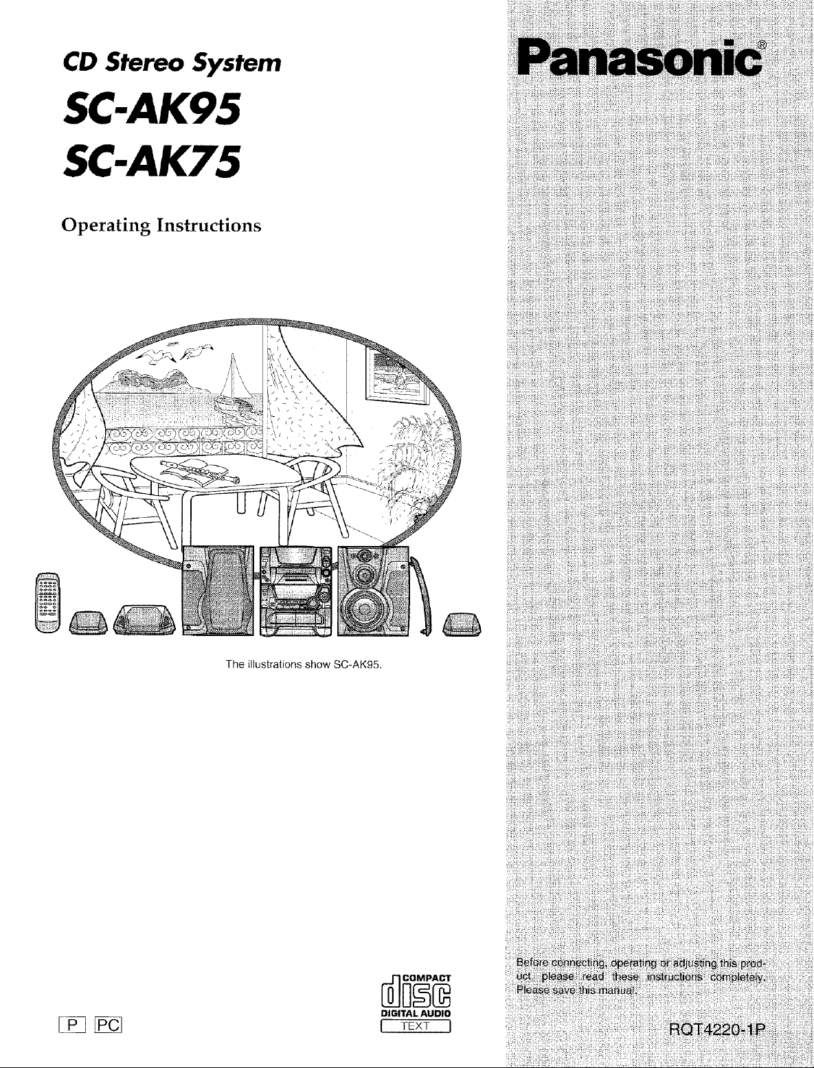
CD Stereo System
SC-AK95
SC-AK75
Operating Instructions
The illustrations show SC-AK95.
DIGITAL AUDIO
I rEXT I
Dear customer
Thank you for purchasing this product.
For optimum performance and safety, please read these instruc
tions carefully.
These operating instructions are applicable to the following
systems,
These operating instructions, however, fundamentally explain the
operation of system SC-AKg5,
Supplied accessories ........................... 2
Precautions ................................... 4
Concerning the remote control ................... 5
Placement of speakers .......................... 6
Connections .................................. 7
t_
System
Main unit
SC-AK95
SA-AK95
SC-AK75
SA-AK75
Basicconnections (for supplied accessories) .............. 7
Optional antennaconnections .......................... 8
Externatunitconnection .............................. 8
Front panel controls ............................ 9
Front
Speakers Center
Surround
SB-AK95
SB-PC55
SB=PS55
SB-AK75
SB-PS55A
Dame function ................................ 11
Setting the time ............................... 11
Presetting radio broadcasts .................... 12
The model number and seria! number of this product can be
found on either the back or the bottom of the unit.
Please note them in the space provided below and keep for
future reference.
Main unit
Speakers
User memo:
DATE OFPURCHASE
DEALER NAME
DEALER ADDRESS
TELEPHONE NUMBER
MODEL NUMBER
SERIAL NUMBER
Listening to radio broadcasts ................... 13
Listening to CDs .............................. 14
Setting/Removing CDs ............................... 14
Sequential play ..................................... 15
Direct access play ................................... 16
Single CD play ..................................... 17
Repeat play ........................................ 17
Random play ....................................... 17
Program p_ay ....................................... 18
To {isten to special CDs and tracks
(CD MANAGER function) ........................... 20
CD-TEXT function ................................... 21
CAUTION_
THIS PRODUCT UTILIZES A LASER.
USE OF CONTROLS OR ADJUSTMENTS OR PERFORM-
ANCE OF PROCEDURES OTHER THAN THOSE SPECI-
FIED HEREIN MAY RESULT IN HAZARDOUS RADIATION
EXPOSURE.
DO NOT OPEN COVERS AND DO NOT REPAIR
YOURSELF. REFER SERVICING TO QUALIFIED
PERSONNEL.
CAUTION:
TO PREVENT ELECTRIC SHOCK MATCH
WIDE BLADE OF PLUG TO WIDE SLOT,
FULLY INSERT.
Listening to tapes ............................. 25
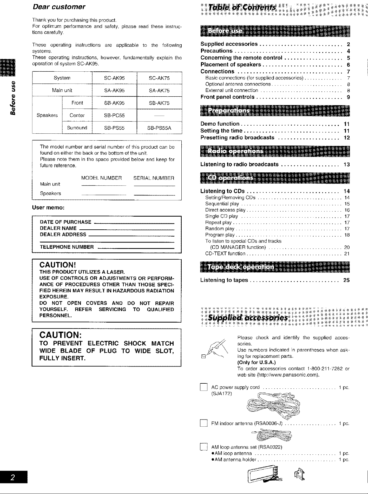
Please check and identify the supplied acces-
sories.
Use numbers indicated in parentheses when ask _
ing for replacement parts_
(Only for U.S.A.)
To order accessories contact 1-800_211W262 or
web site (http:/iwww.panasonic.com).
] AC power supply cord ........................... 1 pc.
(SJA172)
] FM indoor antenna (RSA0006-J) ................... I pc.
[_ AM loop antenna set (RSAO022)
eAM loop antenna .............................. 1 pc.
oAM antenna holder ............................. 1 pc.
THE FOLLOWING APPLIES ONLY IN THE U.S,A.:
Using the built-in sound quality/sound field
settings .................................... 27
Boosting the super woofer ..................... 27
Varying the sound quality with the acoustic image
(AI) equalizer ............................... 28
Varying the sound quality with the manual
equalizer ................................... 29
Enjoying sound with DDLBY PRO LOGIC ......... 30
Before recording .............................. 32
Recording from radio broadcasts ................ 33
Recording from CDs ........................... 34
Tape-to-tape recording ......................... 36
Convenient functions .......................... 37
Singing along with KARAOKE ................... 38
Using the timer ............................... 40
Using an external unit ......................... 43
Concerning CDs .............................. 44
Concerning cassette tapes ..................... 44
Technical specifications ....................... 45
Troubleshooting guide ......................... 46
Maintenance ................................. 47
Before moving or shipping this
system ............................. Back cover
Product service ........................ Back cover
CAUTION:
This equipment has been tested and found to comply with
the limits for a Class B digital device, pursuant to Part t5 of
the FCC Rules.
These limits are designed to provide reasonable protection
against harmful interference in a residential installation. This
equipment generates, uses and can radiate radio frequency
energy and, if not installed and used in accordance with the
instructions, may cause harmful interference to radio commu-
nications. However, there is no guarantee that interference
wil! not occur in a particular installation. If this equipment
does cause harmful interference to radio or television
reception, which can be determined by turning the equipment
off and on, the user is encouraged to try to correct the
interference by one of the following measures:
Reorient or relocate the receiving antenna.
• lncrease the separation between the equipment and re-
ceiver,
• Connect the equipment into an outlet on a circuit different
from that to which the receiver is connected.
• Consult the dealer or an experienced radioiqV technician
for help,
FCC Notice: This system complies with new Part 15, except
for the radio receiver, which complies with o}d Part 15,
Subpart C of the FCC Rules. Operation is subject to the
following two conditions: (1) This device may not cause
harmful interference, and (2) this device must accept any
interference received, including interference that may cause
undesirable operation. The radio receiver is not subject to
above item (2).
Any unauthorized changes or modifications to this equipment
would void the user's authority to operate this device.
WARNING:
TO REDUCE THE RISK OF FIRE, ELECTRIC
SHOCK OR PRODUCT DAMAGE, DO NOT
EXPOSE THIS APPLIANCE TO RAIN,
SPLASHING, DRIPPING OR MOISTURE,
_Q
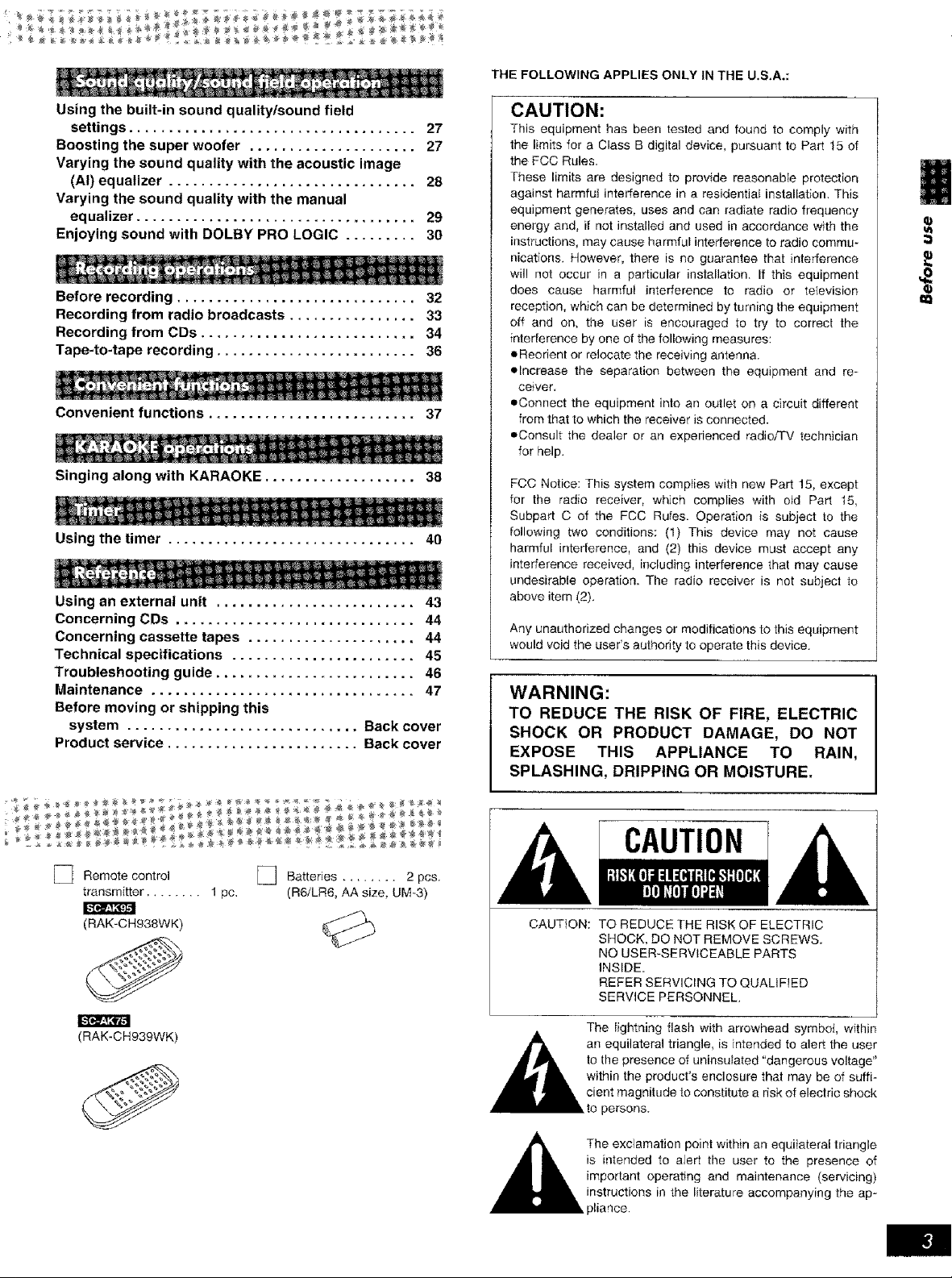
] Remote control
transmitter ........ 1 pc.
(RAK-CHg38WK)
(RAK-CH939WK)
] Batteries ........ 2 pcs.
(R6/LR6, AA size, UM_3)
CAUTION
CAUTION:
_The point within an equilateral triangle
TO REDUCE THE RISK OF ELECTRIC
SHOCK, DO NOT REMOVE SCREWS.
NO USER-SERVICEABLE PARTS
INSIDE.
REFER SERVICING TO QUALIFIED
SERVICE PERSONNEL.
The lightning flash with arrowhead symbol, wfthin
an equilateral triangle, is intended to alert the user
to the presence of uninsulated "dangerous voltage"
within the product's enclosure that may be of suffi-
cient magnitude to constitute a risk of electric shock
persons,
exclamation
is intended to aJert the user to the presence of
important operating and maintenance (servicing)
instructions in the literature accompanying the ap-
pliance.
Beforeusingthisunitpleasereadtheseoperatinginstructionscare°
fully.Takespeciaicaretofollowthewarningsindicatedontheunit
itselfaswellasthesafetysuggestionslistedbelow.
Afterwardskeepthemhandyforfuturereference.
1.Power Source--The unit should be connected to power supply
only of the type described in the operating instructions or as
marked on the unit.
2, Polarizationi_f the unit is equipped with a polarized AC power
plug (a plug having one blade wider than the other), that plug wiil
fit into the AC outlet only one way. This is a safety feature, if you
are unabfe to insert the plug fully into the outlet, try reversing the
plug. If the plug should still fail to fit, contact your electrician to
replace your obsolete outlet. Do not defeat the safety purpose of
the polarized plug.
3. Power Cord Proteotion--AC power supply cords should be
routed so that they are not likely to be walked on or pinched by
items placed upon or against them. Never take hoed of the plug
or cord if your hand is wet, and always grasp the plug body
when connecting or disconnecting it.
4. Nonuse Periods--When the unit is not used, turn the power off.
When left unused for a long period of time, the unit should be
unplugged from the household AC outlet,
Environment
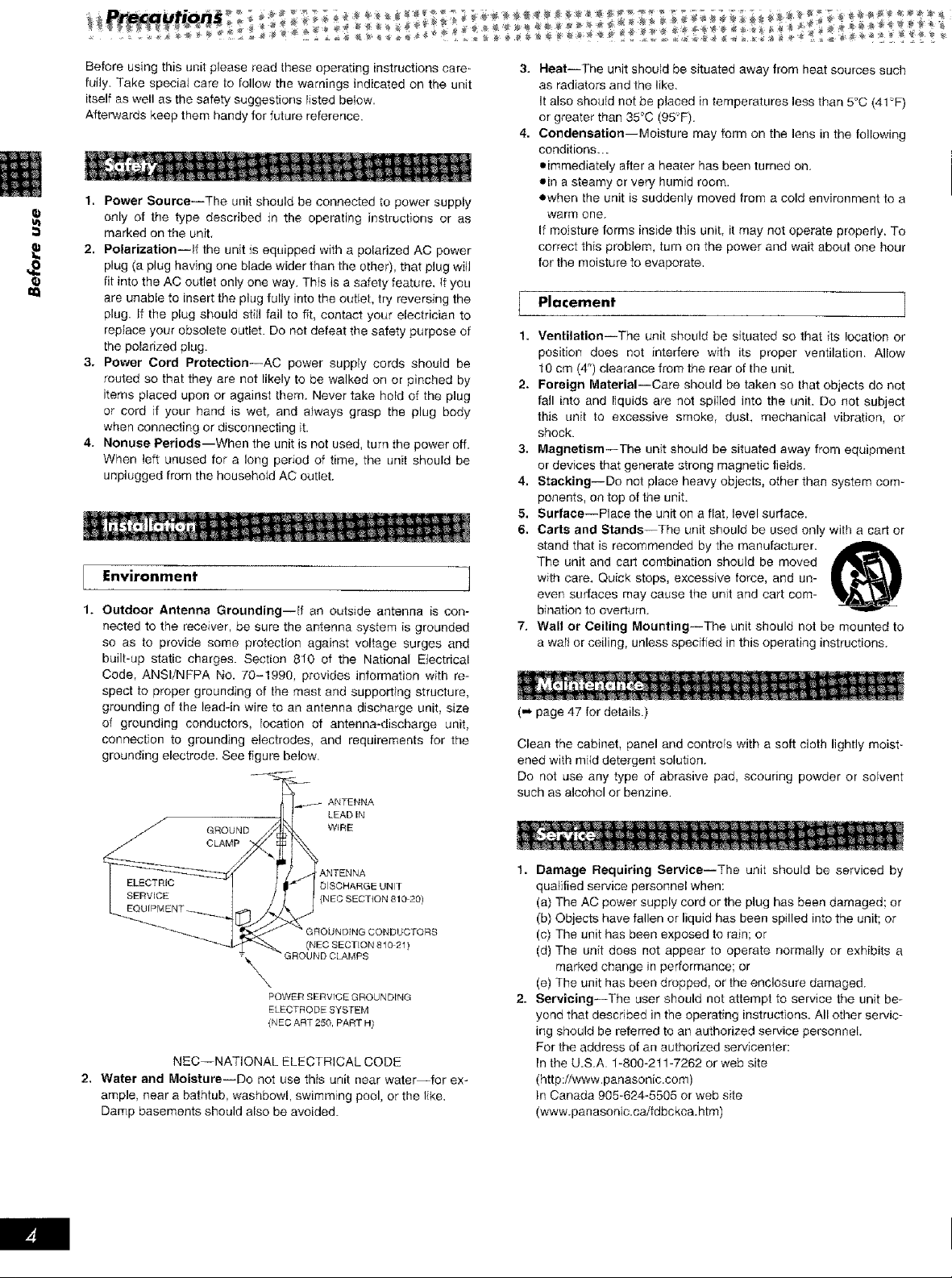
Outdoor Antenna Grounding--If an outside antenna is con-
nected to the receiver, be sure the antenna system is grounded
so as to provide some protection against voltage surges and
built-up static charges. Section 810 of the National Electrical
Code, ANSIiNFPA No. 70-1990, provides information with re-
spect to proper grounding of the mast and supporting structure,
grounding of the lead-in wire to an antenna discharge unit, size
of grounding conductors, location of antenna-discharge unit,
connection to grounding electrodes, and requirements for the
grounding electrode. See figure below.
ANTENNA
GROUND WiRE
CLAMP
LEAD IN
Heat--The unit should be situated away from heat sources such
as radiators and the like.
It also shouJd not be placed in temperatures less than 5:'C (41-'F)
or greater than 35°C (95'F).
4,
Condensation--Moisture may form on the lens in the following
conditions...
oimmediately after a heater has been turned on.
ein a steamy or very humid room.
ewhen the unit is suddenly moved from a cold environment to a
warm one.
If moisture forms inside this unit, it may not operate properly. To
correct this problem, turn on the power and wait about one hour
for the moisture to evaporate.
Placement -]
1.
VentilationiThe unit should be situated so that its location or
position does not interfere with its proper ventilation. Allow
10 cm (4") clearance from the rear of the unit.
2.
Foreign MaterialiCare should be taken so that objects do not
fall into and liquids are not spilIed into the unit_ Do not subject
this unit to excessive smoke, dust. mechanical vibration, or
shock.
3.
Magnetism--The unit should be situated away from equipment
or devices that generate strong magnetic fields.
4.
Stacking--Do net place heavy objects, other then system com-
ponents, on top of the unit.
5,
Surface--Place the unit on a flat, level surface.
6.
Carts and Stands--The unit should be used only with a cad or
stand that is recommended by the manufacturer.
The unit and cart combination should be moved
with care. Quick stops, excessive force, and un-
even surfaces may cause the unit and cart com-
bination to overturn.
Wall or Ceiling Mounting--The unit should not be mounted to
a waif or ceiling, unless speciffed in this operating instructions.
("_ page 47 for details.)
Clean the cabinet, panel and controls with a soft cloth lightly moist°
ened with mitd detergent solution.
Do not use any type of abrasive pad, scouring powder or solvent
such as alcohol or benzine.
ANTENNA
DISCHARGE UNIT
_M_ENT _.__ [_j {NEe SECT{ON 810 20)
__.._ " _NRFcSECT,ON 810 21)
\
GROUNDING CONDUCTORS
"GROU ND CLAMPS
,\
POWER SERVIGE GROUNDING
ELECTRODE SYSTEM
{NEe ART 250 PART N)
NEC--NATIONAL ELECTRICAL CODE
2. Water and Moisture--Do not use this unit near water--for ex-
ample near a bathtub, washbowl, swimming pool, or the I_ke.
Damp basements should also be avoided.
1. Damage Requiring Service--The unit should be serviced by
qualified service personnel when:
(a) The AC power supply cord or the plug has been damaged: or
(b) Objects have fallen or liquid has been spilled into the unit; or
(c) The unit has been exposed to rain; or
(d) The unit does not appear to operate normally or exhibits a
marked change in performance; or
(e) The unit has been dropped, or the enclosure damaged.
2. Servicing--The user should not attempt to service the unit be-
yond that described in the operating instructions. All other servic-
ing should be referred to an authorized service personnel.
For the address of an authorized servicenter:
In the U.S.A. 1-800-211-7262 or web site
(http:iiwww.panasonic.com)
ir', Canada 905-624-5505 or web site
(www.panasonic.caifdbc kca.htm)
Selectingfineaudioequipmentsuchastheunityou'vejust pur-
chased is only the start of your musical enjoyment. Now it's time to
consider how you can maximize the fun and excitement your equip-
ment offers. This manufacturer and the Electronic industries Associ-
ation's Consumer Electronics Group want you to get the most out of
your equipment by playing it at a safe level. One that lets the sound
come through loud and clear without annoying blaring or
distortion--and, most importantly, without affecting your sensitNe
hearing.
We recommend you to avoid prolonged exposure to excessive
noise.
Sound can be deceiving. Over time your hearing "comfort level"
adapts to higher volumes of sound. So what sounds "normal" can
actually be loud and harmful to your hearing.
Guard against this by setting your equipment at a safe level
BEFORE your hearing adapts.
To establish a safe level:
oStart your volume control at a Iow setting.
eSlowly increase the sound until you can hear it comfortably and
clearly, and without distortion.
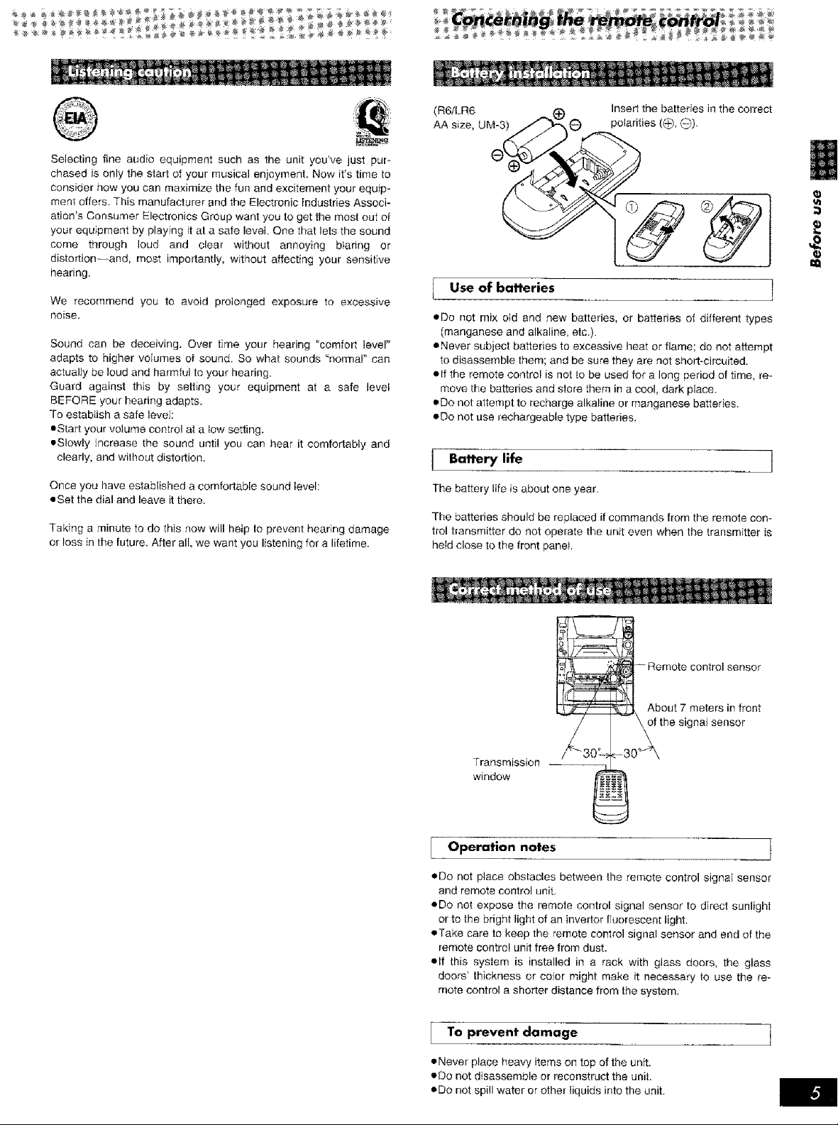
(R6/LR6 Insertthebatteriesinthecorrect
AAsize,UM-3) 0).
l se of batteries 1
eDo not mix old and new batteries, or batteries of different types
(manganese and aika}ine, etc.).
eNever subject batteries to excessive heat or flame; do not attempt
to disassemble them; and be sure they are not short-circuited.
elf the _emote control is not to be used for a long period of time, re-
move the batteries and store them in a cool, dark pface.
eDo not attempt to recharge alkaline or manganese batteries.
eDo not use rechargeable type batteries.
Battery life
Once you have established a comfortable sound level:
eSet the dial and leave it there.
Taking a minute to do this now will help to prevent hearing damage
or loss in the future. After all, we want you listening for a lifetime.
The battery lifeis about oneyear.
The bafteries shoulc_ be replaced if commands item the remote con-
trol transmitter do not operate the unit even when the transmitter is
held close to the front panel,
sensor
About 7 meters in front
of the signal sensor
Transmission
window
'l Operation notes t
eDo not place obstacles between the remote control signal sensor
and remote control unit.
oDo not expose the remote control signal sensor to direct sunlight
or to the bright light of ar_invertor fluorescent light,
eTaKe care to keep the remote control signal sensor and end of the
remote control unit free from dust.
elf this system is installed in a rack with glass doors, the glass
doors' thickness or coJor might make it necessary to use the re-
mote control a shorter distance from the system,
To prevent damage t
• Never place heavy items on top of the unit,
• Do not disassemble or reconstruct the unit.
oDo not spill water or other liquids into the unit.
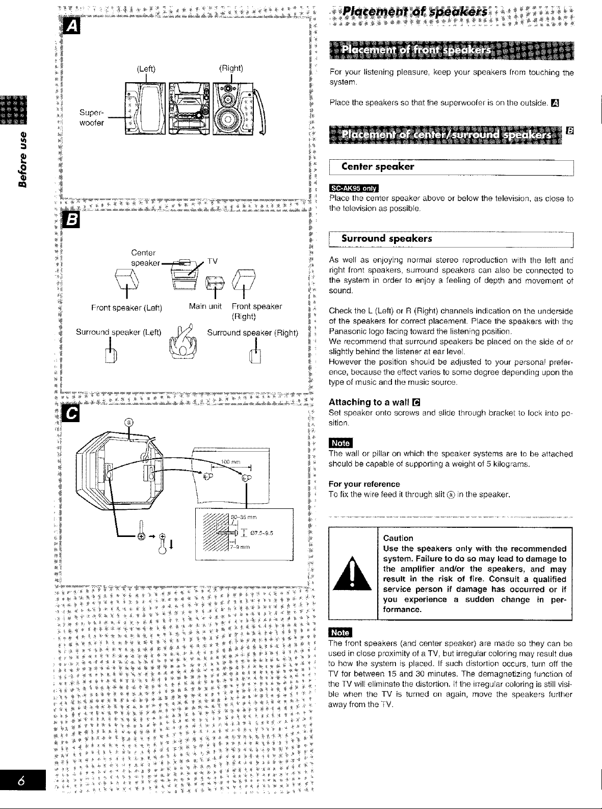
(Left) (Right)
Super-
woofer
÷ Center
_ speaker_ rV
_j
For your listening pleasure, keep your speakers from touching the
system.
Ptace the speakers so that the superwoofer is on the outside. []
Center speaker ]
}*
Place the center speaker above or below the television, as close to
the television as possible,
Surround speakers ]
As well as enjoying normal stereo reproduction with the left and
i.k
right front speakers, surround speakers can also be connected to
the system in order to enjoy a feeling of depth and movement of
sound.
Front speaker (Loft) Main unit Front speaker
(Right)
Surround speaker (Left) Surround speaker (Right)
Check the L (Left) or R (Right) channels indication on the underside
of the speakers for correct placement. PIace the speakers with the
Panasonic logo facing toward the listening position.
We recommend that surround speakers be placed on the side of or
slightly behind the listener at ear level.
, However the position should be adjusted to your personal prefer-
ence, because the effect varies to some degree depending upon the
type of music and the music source.
Attaching to a wall []
Set speaker onto screws and slide through bracket to lock into po-
sition.
k_
The wall or pillar on which the speaker systems are to be attached
should be capable of suppoding a weight of 5 kilograms.
For your reference
To fix the wire feed it through slit (a)in the speaker,
Caution
Use the speakers only with the recommended
system. Failure to do so may lead to damage to
the amplifier and/or the speakers, and may
result in the risk of fire. Consult a qualified
service person if damage has occurred or if
you experience a sudden change in per-
formance.
The front speakers (and center speaker) are made so they can be
used in close proximity of a TV, but irregular coloring may result due
to how the system is placed. If such distodion occurs, turn off the
TV for between 15 and 30 minutes. The demagnetizing function of
the TV will eliminate the distortion, If the irregular coloring is still visi-
ble when the TV is turned on again, move the speakers further
away from the TV.
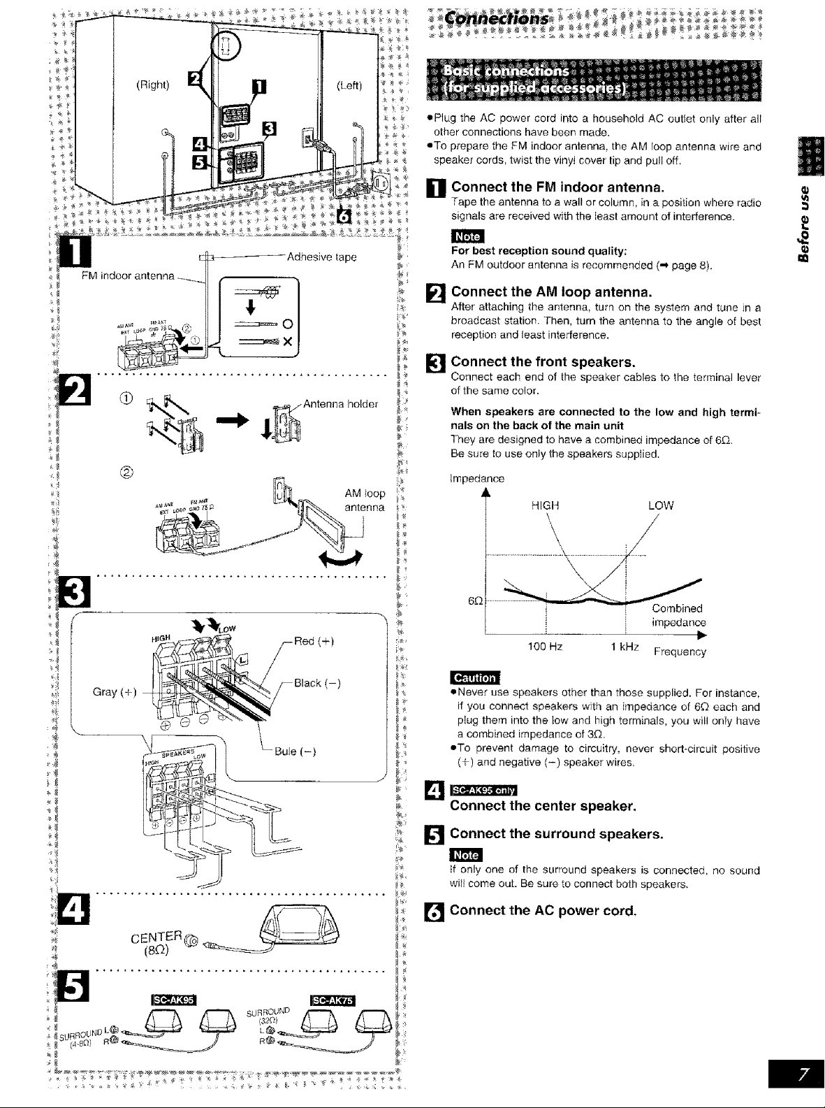
• Plug the AC power cord into a household AC outlet only after all
other connections have been made.
• To prepare the FM indoor antenna, the AM loop antenna wire and
speaker cords, twist the vinyl cover tip and pull off,
D Connect the FM indoor antenna.
Tape the antenna to a wall or column, in a position where radio
signals are received with the least amount of interference.
12_ _ _
FM indoor antenna _ , . ._
Adhesive tape
d)
®
_4
Gray (+)
d
:@
holder
For best reception sound quality;
An FM outdoor antenna is recommended (,_ page 8).
Connect the AM loop antenna.
I]
After attaching the antenna, turn on the system and tune Jn a
broadcast station. Then, turn the antenna to the angle of best
reception and ]east interference.
_ Connect the front speakers.
lk-'ll
_ Connect each end of the speaker cables to the terminal lever
_ of the same color.
When speakers are connected to the low and high termi =
nals on the back of the main unit
They are designed to have a combined impedance of 6_Q.
Be sure to use only the speakers supplied.
Impedance
HIGH LOW
Combined
impedance
100 Hz 1 kHz
• Never use speakers other than those supplied. For instance,
if you connect speakers with an impedance of 60 each and
plug them into the low and high terminals, you will only have
a combined impedance of 3D_.
• To prevent damage to circuitry, never shorbcircuit positive
(÷) and negative (-) speaker wires,
Frequency
18
Connect the center speaker,
[] Connect the surround speakers.
_fonly one of the surround speakers is connected, no sound
wif_ come out. Be sure to connect both speakers.
[P_] Connect the AC cord,
power
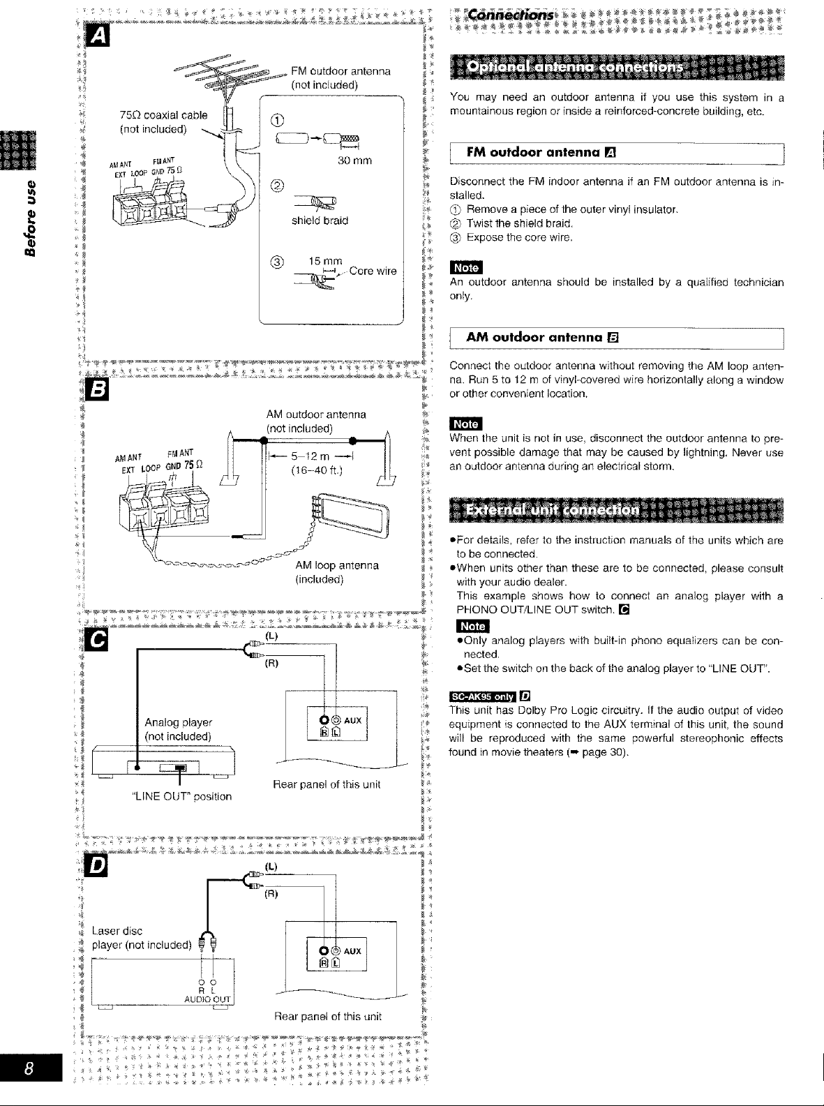
75Dcoaxialcable
(notincluded)
FMoutdoorantenna _
(notincluded)
@
You may need an outdoor antenna if you use this system in a
mountainous region or inside a reinforced-concrete building, etc.
a
AMANT FM_T b_- 5 12 m
EXT LOOP Ii O 75_ (t6-40 ft.) ___b
/
l
>{
_8
_ AM loop antenna
30 mm
@
shield braid
(_) 15 mm
_,- Core wire
AM outdoor antenna
not included)
(included)
FM outdoor antenna [] ]
Disconnect the FM indoor antenna if an FM outdoor antenna is in-
stalled.
_._ Remove a piece of the outer vinyl insulator.
Twist the shield braid•
(_ Expose the core wire.
An outdoor antenna should be installed by a qualified technician
only.
AM outdoor antenna []
Connect the outdoor antenna without removing the AM loop anten-
na. Run 5 to 12 m of vinyl-covered wire horizontally along a window
or other convenient location.
When the unit is not in use, disconnect the outdoor antenna to pre-
q_
vent possible damage that may be caused by lightning. Never use
an outdoor antenna during an electrical storm.
• For details, refer to the instruction manuals of the units which are
}4
to be connected.
•When units other than these are to be connected, please consult
_4
with your audio dealer.
This example shows how to connect an analog player with a
PHONe OUT/LINE OUT switch. []
_8
_ Analog player _:_.
(not included) _
_:_ _
"LINE OUT" position __,
player (not included)
_ AU r
Rear panel of this unit
Rear panel of this unit _:
• Only analog players with buitt-in phone equalizers can be con-
nected.
• Set the switch on the back of the analog player to "LINE OUT".
¢
This unit has Dolby Pro Logic circuitry. If the audio output of video
equipment is connected to the AUX terminal of this unit, the sound
will be reproduced with the same powerful stereophonic effects
found in movie theaters (,,,,page 30).
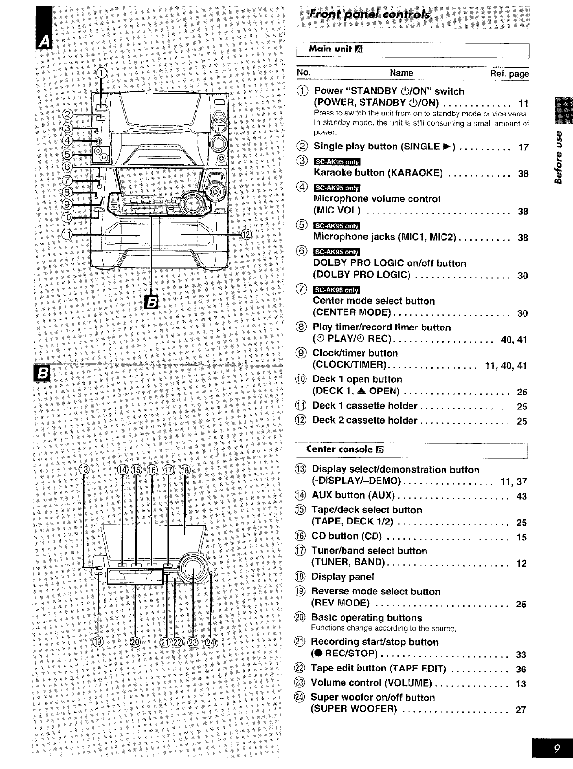
t Main unit [] 1
No. Name Ref. page
Power "STANDBY (_/ON" switch
(POWER, STANDBY (_/ON) ............. 11
Press to switch the unit from on to standby mode or vice versa.
In standby mode, the unit is still consuming a sinai{ amount of
power.
(_ Single play button (SINGLE I_) .......... 17
Karaoke button {KARAOKE) ............ 38
Microphone volume control
(MIC VOL) ........................... 38
Microphone jacks (MlCl, MIC2) .......... 38
DOLBY PRO LOGIC on/off button
(DOLBY PRO LOGIC) .................. 30
Center mode select button
(CENTER MODE) ...................... 30
(_) Play timer/record timer button
(_ PLAW_) REC) ................... 40, 41
(_ ClockJtimer button
(CLOCK/TIMER) ................. 11, 40, 41
(_) Deck 1 open button
(DECK 1, _ OPEN) .................... 25
(_) Deck 1 cassette holder ................. 25
(_) Deck 2 cassette holder ................. 25
Center console [] ]
Display select/demonstration button
(-DISPLAY/-DEMO) ................. 11, 37
(_) AUX button (AUX) ..................... 43
(_) Tapetdeck select button
(TAPE, DECK 1/2) ..................... 25
(1.__CD button (CD) ....................... 15
(_) Tunerlband select button
(TUNER, BAND) ....................... 12
_) Display panel
(_) Reverse mode select button
(REV MODE) ......................... 25
(_ Basic operating buttons
Functions change according to the source,
Recording start/stop button
(_ REC/STOP) ........................ 33
(_ Tape edit button (TAPE EDIT) ........... 36
_) Volume control (VOLUME) .............. 13
(_) Super woofer on/off button
(SUPER WOOFER) .................... 27
¢Q
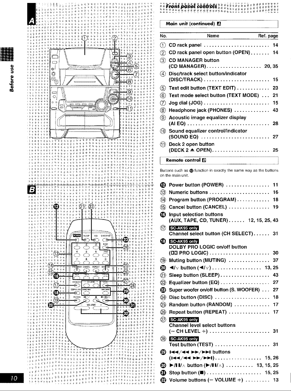
Main unit (continued) [] 1
No. Name Ref.page
(_ CD rack panel ........................ 14
CD rack panel open button (OPEN) ....... 14
CD MANAGER button
(CD MANAGER) .................... 20, 35
Disc/track select button/indicator
(DISC/TRACK) ........................ 15
(_ Text edit button (TEXT EDIT) ............ 23
(_ Text mode select button (TEXT MODE) ... 21
(_ Jog dial (JOG) ........................ 15
(_ Headphone jack (PHONES) ............. 43
(_ Acoustic image equalizer display
(AI EO) .............................. 28
(_ Sound equalizer controllindicator
(SOUND EQ) ......................... 27
@ Deck 2 open button
(DECK 2 A OPEN) ..................... 25
I emote control []
Buttons such as I_)function in exactly the same way as the buttons
on the main unit,
(D Power button (POWER) ................ 11
_) Numeric buttons ...................... 16
(_ Program button (PROGRAM) ............ 18
(_ Cancel button (CANCEL) ............... 19
_) Input selection buttons
(AUX, TAPE, CD, TUNER) ...... 12, 15, 25, 43
Channel select button (CH SELECT) ...... 31
DOLBY PRO LOGIC on/off button
(DR PRO LOGIC) ...................... 30
@) Muting button (MUTING) ............... 37
(_) <Iv button (<l/v) .................. 13, 25
(_ Sleep button (SLEEP) .................. 43
_) Equalizer button (EQ) .................. 27
(_) Super woofer onloff button (S. WOOFER) ... 27
___ Disc button (DISC) .................... 18
(_ Random button (RANDOM) ............. 17
Repeat button (REPEAT) ............... 17
Channel level select buttons
(- OH LEVEL +) ...................... 31
Test button (TEST) .................... 31
(_ I<1</_1< _/I,,I,4 buttons
(i_1_I/<1_ 1_/_1) ................. 15, 26
_) I_/11/^ button (1_/11/_) .......... 13, 15, 25
(_) Stop button (I) .................... 15, 25
(_ Volume buttons (- VOLUME +) ......... 13
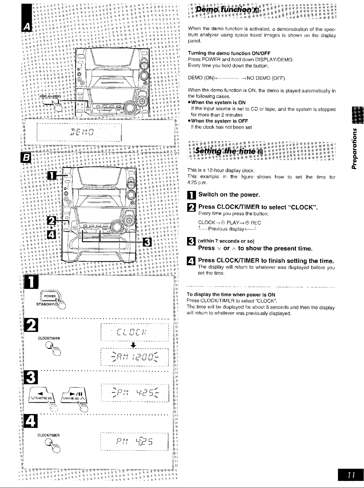
When the demo function is activated, a demonstration of the spec-
trum analyzer using space travel images is shown on the display
panel,
Turning the demo function ON/OFF
Press POWER and hold down DISPLAY/DEMO
Every time you hold down the button;
DEMO (ON) ÷ -.NO DEMO (OFF)
When the demo function is ON, the demo is played automatically in
the following cases.
,=When the system is ON
If the input source is set to CD or tape, and the system is stopped
for more than 2 minutes
•When the system is OFF
]f the clock has not been set
This is a 12-hour display clock.
This exampte in the figure shows how to set the time for
4:25 p m
t
O Switch on the
power.
Press CLOCK/TIMER to select "CLOCK".
Every time you press the button;
CLOCK_->_ PLAY-_) REC
t_Previous displaye--J
_'] (within 7 seconds or so)
Press v or A to show the present time,
[] Press CLOCK/TiMER to finish setting the time.
The display will return to whatever was displayed before you
set the time.
_ To display the time when power is ON
The time will be displayed for about 5 seconds and then the display
will return to whatever was previously displayed.
.o select CLOCK._ Press CLOCK/TIMER f ....
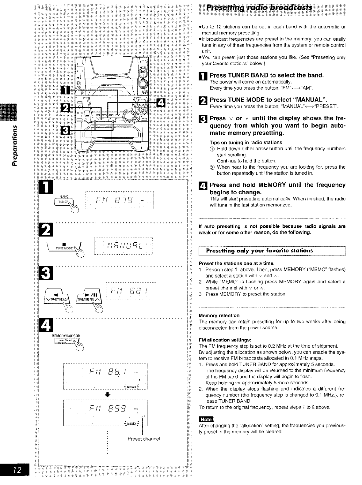
pUp to 12 stations can be set in each band with the automatic or
manua_ memory presetting.
• If nroaocast frequencies are preset in the memory, you can easily
tune in any of these frequencies from the system or remote control
unit.
• You can preset _ust those stations you like. (See "Presetting only
your favorite stations" below.)
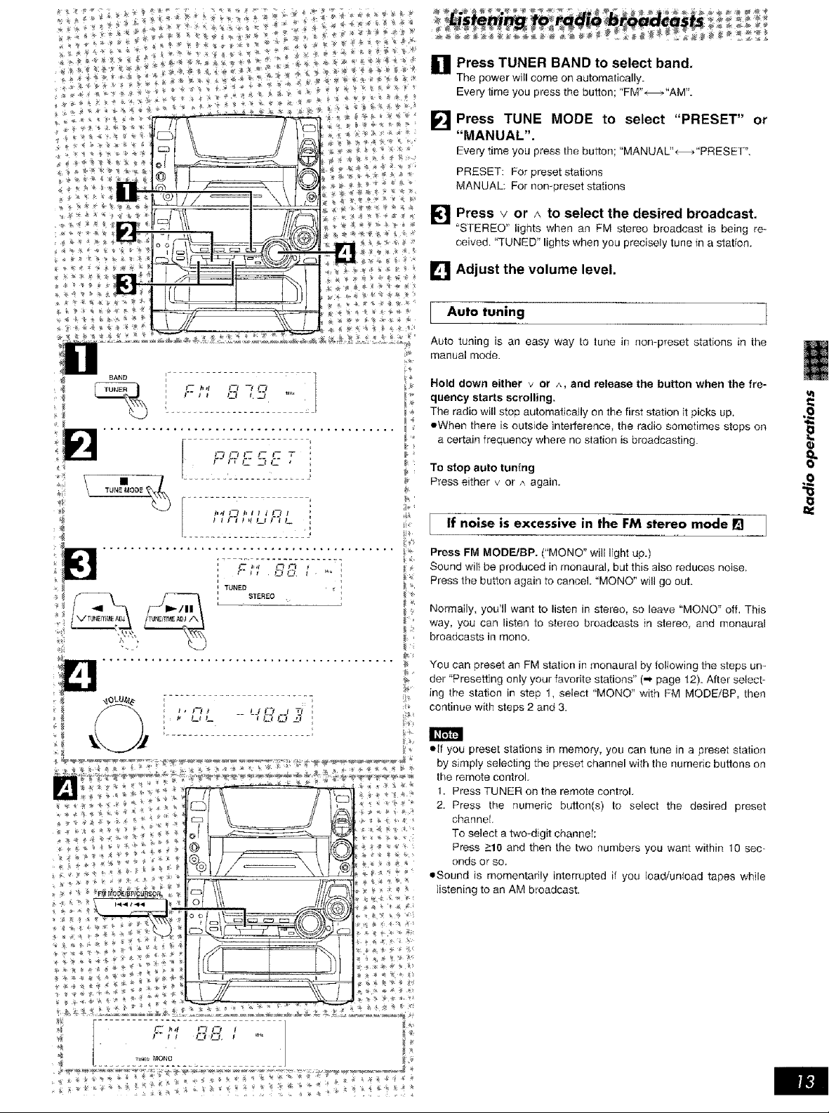
Press TUNER BAND to select the band.
U
The power will come on automatically.
-_-veryhme you press the button; "FM"_ _-_"AM".
Press TUNE MODE to select "MANUAL".
:_very time you press the button; "MANUAL"_"PRESET".
Press v or A until the display shows the fre-
[]
I=
quency from which you want to begin auto-
rnatic memory presetting.
Tips on tuning in radio stations
Hold down either arrow button until the frequency numbers
start scrolhng.
Continue to hotd the button.
When near to the frequency you are looking for, press the
3utton repeatedly until the station is tuned in.
Press and hold MEMORY until the frequency
[]
begins to change.
This will start presetting automatically. When finished, the radio
will tune in the last station memorized.
_4
TUNE MODE
MEMORY/CURSOR
s F] _ 1_L_ F] L
......L___: .... __
41-
If auto presetting is not possible because radio signals are
weak or for some other reason, do the foltowing.
Presetting only your favorite stations ]
Preset the stations one at a time.
1. Perform step 1 above, Then, press MEMORY ("MEMO _ flashes)
and select a station with v and P,.
2. While "MEMO _' is flashing press MEMORY again and select a
_4
preset channel with v or ^.
3. Press MEMORY to preset the station.
Memory retention
The memory can retain presetting for up to two weeks after being
disconnected from the power source.
FM allocation settings:
The FM frequency step is set to 0.2 MHz at the time of shipment.
By adjusting the allocation as shown below, you can enable the sys_
tern to receive FM broadcasts allocated in 0.1 MHz steps.
1. Press and hold TUNER BAND for approximately 5 seconds•
The frequency display will be returned to the minimum frequency
of the FM band and the display will begin to flash,
Keep holding for approximately 5 more seconds.
2. When the display stops flashing and indicates a different fre-
quency number (the frequency step is changed to 0.1 MHz.), re-
}ease TUNER BAND.
To return to the original frequency, repeat steps 1 to 2 above.
_Y
.................
t-- I_,t I--t _% Ff
After changing the "allocation" setting, the frequencies you previous-
ly preset in the memory will be cleared.
Preset channel
• _ __ _ _ _ _ _ f__ _ _ _
Press TUNER BAND to select band.
M
The power will come on automatically.
Every time you press the button; "FM"-_,"AM'_
Press TUNE MODE to select "PRESET" or
"MANUAL".
Every time you press the button; "MANUAL"<-_>"PRESET _',
PRESET: For preset stations
MANUAL: For non-preset stations
B Press v or _ to select the desired broadcast.
"STEREO" lights when an FM stereo broadcast is being re-
ceived. "TUNED" lights when you precisely tune in a station.
[] Adjust the volume level.
Auto tuning
Auto tuning is an easy way to tune in non-preset stations in the
manual mode.
Hold down either v or ^, and release the button when the fre-
quency starts scrolling.
The radio will stop automatically on the first station it picks up,
eWhen there is outside interference, the radio sometimes stops on
a certain frequency where no station is broadcasting.
To stop auto tuning
Press either v or A again.
if noise is excessive in the FM stereo mode 19
Press FM MODE/BP. ("MONO" will light up.)
Sound will be produced in monaural, but this also reduces noise,
Press the button again to cancel. "MONO" will go out.
Normally, you'll want to listen in stereo, so leave "MONO" off. This
way, you can listen to stereo broadcasts in stereo, and monaural
broadcasts in mono.
You can preset an FM station in monaural by following the steps un-
der "Presetting only your favorite stations" (_, page 12). After select-
ing the station in step 1, select "MONO" with FM MODE/BP, then
continue with steps 2 and 3.
• lf you preset stations in memory, you can tune in a preset station
by simply selecting the preset channel with the numeric buttons on
the remote control.
1. Press TUNER on the remote control.
2. Press the numeric button(s) to select the desired preset
channel
To select a two-digit channe[:
Press >10 and then the two numbers you want within 10 sec-
onds or so.
=Sound is momentarily interrupted if you load/unload tapes while
listening to an AM broadcast.
8=
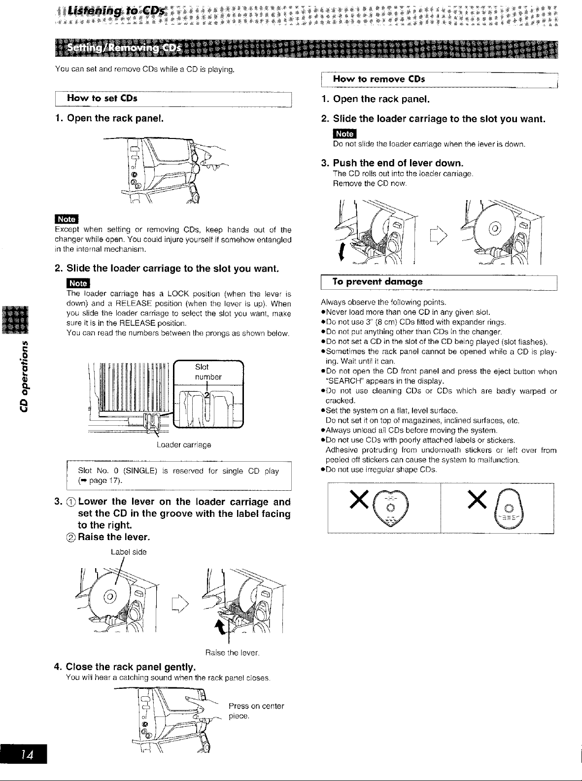
You can set and remove CDs while a CD is playing.
How to set CDs
How to CDs
remove
1. Open the rack panel.
8
1. Open the rack panel.
Except when setting or removing CDs, keep hands out of the
changer while open. You could injure yourself if somehow entangled
in the internal mechanism.
2. Slide the loader carriage to the slot you want,
The loader carriage has a LOCK position (when the lever is
down) and a RELEASE position (when the lever is up}. When
you slide the loader carriage to select the slot you want, make
sure it is in the RELEASE position.
You can read the numbers between the prongs as shown below.
Slot
number
Loader carriage
Slot No. 0 (SINGLE) is reserved for single CD play
(,,* page l 7).
2. Slide the loader carriage to the slot you want.
Do not stide the loader carriage when the tever is down.
3. Push the end of lever down.
The CD rolls out into the loader carriage.
Remove the CD now.
To prevent damage 1
Always observe the following points.
eNever load more than one CD in any given slot.
eDo not use 3" (8 cm) CDs fitted with expander rings.
eDo not put anything other than CDs in the changer.
eDo not set a CD in the slot of the CD being played (slot flashes).
eSometFmes the rack panel cannot be opened while a CD is play-
ing. Wait until it can.
eDo not open the CD front panel and press the eject button when
"SEARCH" appears in 1hedisplay.
eDo not use cleaning CDs or CDs which are badJy warped or
cracked.
eSet the system on a flat, level surface.
Do not set it on top of magazines, inclined surfaces, etc.
eAIways unload aft CDs before moving the system.
eDo not use CDs with poorly attached labels or stickers.
Adhesive protruding from underneath Stickers or left over from
peeled off stickers can cause the system to malfunction.
• Do not use irregufar shape CDs.
3. __)Lower the lever on the loader carriage and
set the CD in the groove with the label facing
to the right.
(_ Raise the lever.
Label side
Raise the lever.
4. Close the rack panel gently.
You witi hear a catching sound when tbe rack panel closes.
_ _ Press on center
piece.
x©
OPEN
JOG .................................. '_
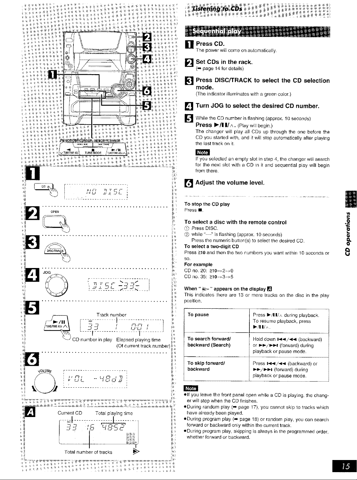
U Press CD,
The power will come on automaticalty.
Set CDs in the rack,
(= page 14 for details)
Press DISC/TRACK to select the CD selection
mode.
(The indicator ilium;hates 'with a green color.)
[] Turn JOG to select the desired CD number,
I_l While the CD number is flashing (approx. t0 seconds)
Press i_/I IliA. (Playwillbegin,)
The changer will play all CDs up through the one before the
CD you started with, and it will stop automatically after playing
the last track on it.
If you selected an empty slot in step 4, the changer witt search
for the next slot with a CD in it and sequential play will begin
from there.
[t_J Adjust the volume level,
To stop the CD play
Press II.
To select a disc with the remote control
Press DISC.
while "--" isflashing (approx, 10 seconds)
Press the numeric buttor_(s) to select the desired CD.
To select a two-digit CD
Press >10 and then the two numbers you want within 10 seconds or
SO.
For example
CD no. 20:>10->2-_0
CD rio. 35:>10--->3-->5
li
il
II
o=
8
When "_" appears on the display []
This indicates there are 13 or more tracks on the disc in the play
position.
To pause
:i
di
Current CD Total playing time
J
I '_mml
Total number of tracks
To search forward/
backward (Search)
To skip forward/
backward
*=Ifyou leave the front panel open while a CD is playing, the chang-
er will atop when the CD finishes.
eDuring random play (,,* page 17), you cannot skip to tracks which
have already been played.
'*_ *=During program play (,,* page 18) or random p_ay, you can search
forward or backward on!y within the current track.
eDuring program play, skipping is always in the programmed order,
whether forward or backward.
Press i,-ll ItA during playback.
To resume p ayback, press
i" ll II A.
Ho_ddown i_li_il/_ii,ii(backward)
or i_i_x'i,>i_i(forward) during
playback or pause mode.
Press i_l-_li_l (backward) or
li,.l_ili,-ii-i (forward) during
playback or pause mode.
i
 Loading...