

Panasonic SC-AK91, SC-AK71 Owner’s Manual
CD Stereo System
SC-AK90/SC-AK91
SC-AK70/SC-AK71
Operating Instructions
Panasonic °
The illustrations show SC-AKg0
DIGITAL AUDIO
Before conn_mg_ operating or adlushng this pro-
duct, please read these instructions thoroughly.
Please save this manual.
RQT3884-2P
I
Dear customer
Thank you for purchasing this product.
For opl_xnum performance and safety, please read these instructions
carefully.
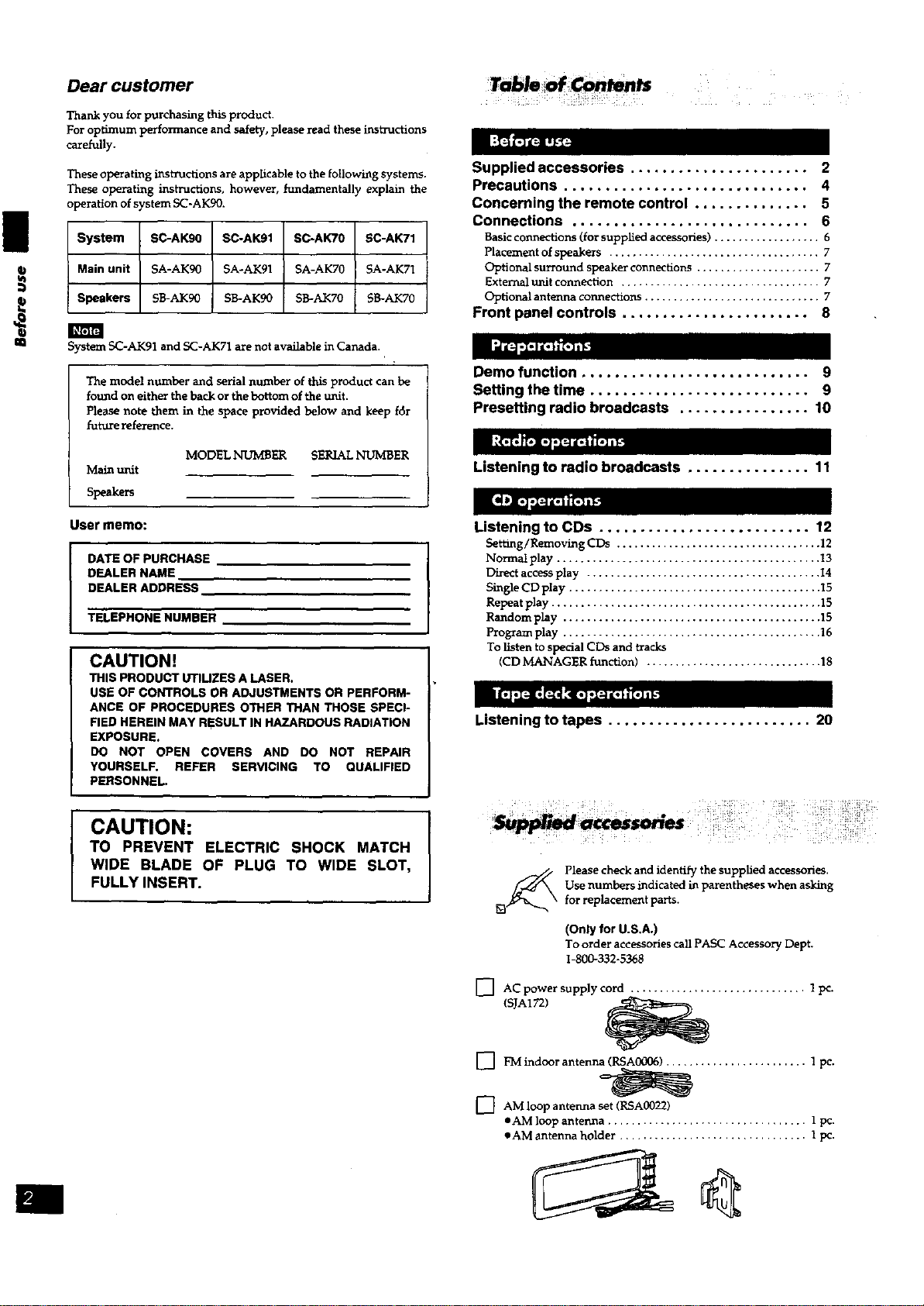
These operating instructions are appEcabla to the following systems.
These operating instructions, however, fundamentally explain the
operation of system SC-AK90.
System SC-AK90 SC-AK91 SC-AK70 SC-AK71
@
@
m
Main unit SA-AKgO SA-AKgl SA-AK70 SA-AKTI
Speakers SB-AKgO SB-AKg9 SB-AK70 SB-AK70
System SC-AK91 and SC-AK71 are not available in Canada.
The model number and serial number of this product can be
found on either the bach or the bottom of the unit.
Please note them in the space provided below and keep f6r
future reference.
Supplied accessories ...................... 2
Precautions .............................. 4
Concerning the remote control .............. 5
Connections ............................. 6
Basic connections (for supplied accessories) .................. 6
Placement of speakers .................................... 7
Optional surround speaker connections ..................... 7
External unit connection .................................. 7
Optional antenna connections .............................. 7
Front panel controls ....................... 8
Demo function ............................ 9
Setting the time ........................... 9
Presetting radio broadcasts ................ 10
Main unit
MODEL NUMBER SERIAL NUMBER
Speakers
U_rmemo:
DATE OF PURCHASE
DEALER NAME
DEALER ADDRESS
TELEPHONE NUMBER
CAUTION!
THIS PRODUCT UTIMZES A LASER.
USE OF CONTROLS OR ADJUSTMENTS OR PERFORM-
ANCE OF PROCEDURES OTHER THAN THOSE SPECI-
FIED HEREIN MAY RESULT IN HAZARDOUS RADIATION
EXPOSURE.
DO NOT OPEN COVERS AND DO NOT REPAIR
YOURSELF. REFER SERVICING TO QUALIFIED
PERSONNEL.
CAUTION:
TO PREVENT ELECTRIC SHOCK MATCH
WIDE BLADE OF PLUG TO WIDE SLOT,
FULLY INSERT.
Listening to radio broadcasts ............... 11
Listening to CDs .......................... 12
Setting/Removing CDs ................................... 12
Normal play ............................................. 13
Direct access play ........................................ I4
Single CD play ........................................... I5
Repeat play .............................................. 15
Random play ............................................ 15
Program play ............................................ 16
To listen to special CDs and t_acks
(CD MANAGER function) .............................. 18
Listening to tapes ........................ . 20
Please check and identify the supplied accessories.
Use numbers indicated in parentheses when asking
for replacement pans.
(Only for U.S.A.)
To order accessories ca]] PASC Accessory Dept.
1-800-332-5368
] AC power supply cord .............................. 1pc.
1SJA172)
] FMindoorantenna(RSA0(X)6) ........................ ] pc.
] AM loop antenna set (RSA0022)
eAM loop antenna .................................. 1 pc.
eAM antenna holder ................................ 1 pc,
THE FOLLOWING iS APPLIED ONLY FOR U.S.A.:
Before recording .......................... 21
Recording from radio broadcasts ............ 22
Recording from CDs ....................... 23
To record special CDs and tracks
(CD MANAGER function) .............................. 24
Tape-to-tape recording ..................... 26
Sound quality, field, etc..................... 27
Singing along with KARAOKE ............... 28"
Timers ................................... 30
Using the play timer ....................... 31
Using the record timer ..................... 32
Using the sleep timer ...................... 33
To use two timers together .................. 34
Convenient functions ...................... 34
Using an external unit ...................... 35
CAUTION:
This equipment has been tested and found to complywith the
limitsfor a Class B digital device, pursuant to Part 15 of the
FCC Rules.
These limits are designed to provide reasonable protection
against harmful interference in a residential installation. This
equipment generates, uses and can radiate radio frequency
energy and, if not installed and used in accordance wRh the
instructions, may cause harmful interference to radio commu-
nications. However, there is no guarantee that intefference
will not occur in a particular installa_on. Ifthis equipment does
cause harmful interference to radio or television reception,
which can be determined by tumingthe equipment off and on,
the user is encouraged to try to correct the interference by one
of the following measures:
eReorient or relocate the receivingantenna.
elncrease the separation between the equipment and ra-
seiver.
eConnect the equipment into an oubet on a circuit different
from that to which the receiver isconnected.
eConsuR the dealer or an experiensed radio/3V technician for
help.
FCC Notice: This system complies with new Part 15, except
for the radio receiver, which complieswith o!d Part 15, Subpart
C of the FCC Rules. Operation is subject to the following two
conditions: (1) This device may not cause harmful interfe-
rense, and (2) this device must accept any interferanse re-
ceived, including interference that may cause undesirable
operation. The radio receiver is not subject to above item (2).
e
m
Remote control buttons and functlons ........ 36
Concerning CDs .......................... 37
Concerning cassette tapes .................. 37
Troubleshooting guide ..................... 38
Maintenance .............................. 39
Technical specifications ............ Back cover
Product service ................... Back cover
Before moving or shipping this
system ........................ Back cover
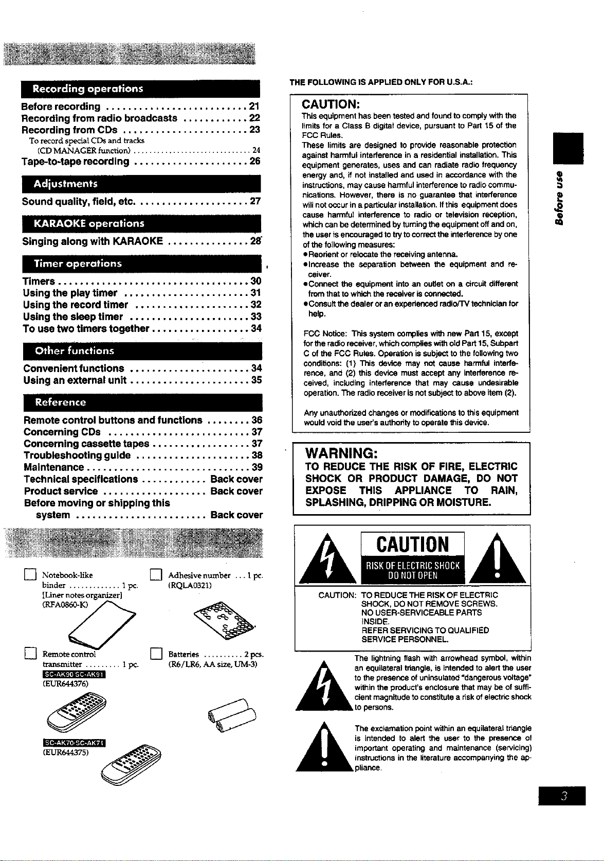
] Notebook-like
binder ............. 1 pc.
[Liner notes organizer]
(RFA0860-_
] Remote control
transmitter ......... 1 pc.
(EUR644376)
] Adhesivenumber ...Ipc.
(RQLA0321)
%.
] Bakeries .......... 2pcs.
(R6/LR6, AAsize, UM-3)
Any unauthorized changes or modifications to this equipment
would void the user's authority to operate this device.
WARNING:
TO REDUCE THE RISK OF FIRE, ELECTRIC
SHOCK OR PRODUCT DAMAGE, DO NOT
EXPOSE THIS APPLIANCE TO RAIN,
SPLASHING, DRIPPING OR MOISTURE.
CAUTION
CAUTION: TO REDUCE THE RISK OF ELECTRIC
SHOCK, DO NOT REMOVE SCREWS.
NO USER-SERVICEABLE PARTS
INSIDE.
REFER SERVICING TO QUALIFIED
SERVICE PERSONNEL.
The lightning flash with arrowhead symbol, within
to the presence of uninsulatad =dangerous voltage"
withinthe product's enclosure that may be of suffi-
an equilateral triangle, is intended to alert the user
cient magnitude to constitute a riskofelectricshock
to persons.
The exclamation point w_thinan equilateral trhangle
is intended to alert the user to the presence of
important operating and maintenance (servicing)
instructions in the literature accompanying the ap-
BJ
|
,2
Before using this unit please read these operating instructions cea_
fully. Take special care to follow the warnings indicated on the unit
itself as well as the safety suggestions listed below.
Afterwards keep them handy for future reference.
3.
Heat--The unit should be situated away from heat sources such
as radiators and the like.
@
¢D
m
1. Power Source--The unit should be connected to power supply
only of the type described in the operating instructions or as
marked on the unit.
2. Polarizatin,a--lf the unit is equipped with a polarized AC power
plug (a plug having one blade wider than the other), that plug w0J
fit into the AC outlet only one way. This is a safety feature. If you
are unable to insert the plug fully into the outlet, try reversing the
plug. If the plug should still fail to fit, contact your elec_ricizn to
replace your obsolete outlet. Do not defeat the safety purpose of
the polarized plug.
3. Power Cord Protection--AC power supply cords should be
routed so that they are not likely to be walked on or pinched by
items placed upon or against them. Never take hold of the plug or
cord if your hand is wet, and always grasp the plug body when
connecting or disconnecting it.
4. Nonuse Perlods--When the unit is net used, turn the power off.
When left unused for a long period of time, the unit should be
unplugged from the household AC outlet.
[W_fl_ rAql_
[
Environment ]
1.
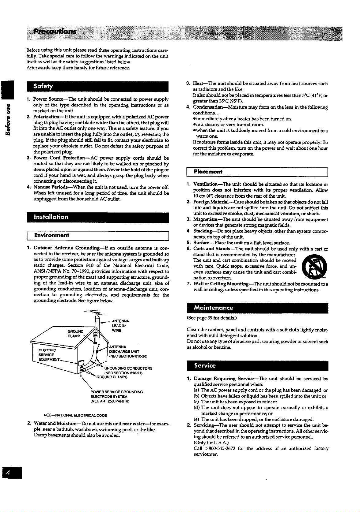
Outdoor Antenna Groundlng--If an outside antenna is con-
nected to the receiver, be sure the antenna system is grounded so
as to provide some protection against voltage surges and built-up
static charges. Sec_on 810 of the National Electrical Code,
ANSI/NFPA No. 70-1990, ivrovides information with respect to
proper grounding of the mast and supporting structure, ground-
ing of the lead-in wire to an antenna discharge unit, size of
grounding conductors, location of antenna-discharge unit, con-
nection to grounding electrode_, and requirements for the
grounding electrode. See figure below.
Italso should not be placed in tempera_wes less than 5_C (41°P) or
greater than 35°C (95_b').
4.
Condensation--Moisture may form on the lens in the following
conditions...
omunediately after a heater has been turned on.
oina steamyorveryhumid room.
ewhen theunitissuddenlymoved from acoldenvironmenttoa
waFff[one.
Ifmoistureformsinsidethisunit,itmay notoperateproperly.To
correctthisproblem,turnon thepower and waitabout one hour
forthem_isturetoevaporate.
I Placement [
1. Ventllatlo_a--The unit should be situated so that its location or
position does not interfere with its proper ve_ttilatlon. Allow
I0 cm (49 clem-ance from the rear of the unit.
2. Foreigu Material--Care should be taken so that objects do net fall
into and liquids are not spilled into the unit. Do not subject this
unit to excessive smoke, dust, mechanical vibration, or shock.
3. Maguetimn--The unit should be situated away from equipment
or devices that generate strong magnetic fields.
4. StackingmDo not place heavy objects, other than system compo-
nents, on top of the unit.
5. Surface--Place the unit on a fiat, level surface.
6. Carts and Stands--The unit should be used only with a cart or
stand that is recommended by the manufacturer.
The unitand cartcombinationshouldBe moved
with care.Quick stops,excessiveforce,and un-
even surfacesmay causetheunitand cartcombi-
nationto overturn.
7. WallozCeilingMounting--The unitshouldnotbemounted toa
wallorceiling,unlessspecifiedinthisoperatinginstructions.
GROUND WIRE
CLAMp
_i ANTENNA
LEADIN
ANTENNA
DISC_IARGE UNIT
(NECSECTION810-20)
GROUNDINGCONDUCTORS
(NEC SECTION810-21)
CLAMPS
\
POWER SERVICE GROUNDING
ELECTRODE SYSTEM
(NECART250,PARTH)
NEC--NAT]ONALELECTRICALCODE
2. Water and Moistuze--Do not use this unit near water-- for exam-
ple, near a bathtub, washbowl, swimming pool, or the like.
Damp basementsshouldalsobeavoided.
(See page 39 for details.)
Clean the calumet, paneland controlswitha softcloth lightly m(Ytst-
enedwithmild detergentsolution.
Do notuseany typeofabrasivepad,scouringpowder orsolventsuch
asalcoholorbenzine.
1. Damage Requiring Service--The unit should be serviced by
qualified service personnel when:
(a) The AC power supply cord or the plug has been damaged; or
(b) Objects have fallen or liquid has been spilled into the unit; or
(c) The unit has been exposed to rain; or
(d) The unit does not appear to operate normally or exhibits a
marked change in performance; or
(e) The unit has been dropped, or the enclosure damaged.
2. Servicing--The user should not attempt to service the unit be-
yond that described in the operating insh-ucfions. All other servic-
ing should be ref_ to an authorized service personnel.
(Only for U.S.A.)
Call 1-800-545-2672 for the address of an authorized factory
servicenter.
Selecting fine audio equipment such as the unit you've just pur-
chased is only the start of your musical enjoyment. Now it's time to
considerhow you can maximize thefun and excitementyour equip-
ment offers.This manufacturer and the mech-onlc Industries
Association'sConsumer ElectronicsGroup want you togetthemost
out ofyourequipmentby playingitata safelevel.One thatletsthe
sound come throughloud and clearwithout annoying blaringor
distortion--and,most importantly,withoutaffectingyoursensitive
hearing.
We recommend you to avoid prolonged exposure to excessive noise.
Sound can be deceiving. Over time your hearing "comfort level"
adapts to higher volumes of sound. So what sounds "normal" can
actually be loud and harmful to your hearing.
Guard against this by setting your equipment at a safe level BEFORE
your hearing adapts.
To establish a safe level:
oStert your volume control at a low setting.
• Slowly increase the sound until you can hear it comfortably and
clearly, and without distortion.
Once you haveestablisheda comfortablesound level:
•Setthedialandleaveitthem.
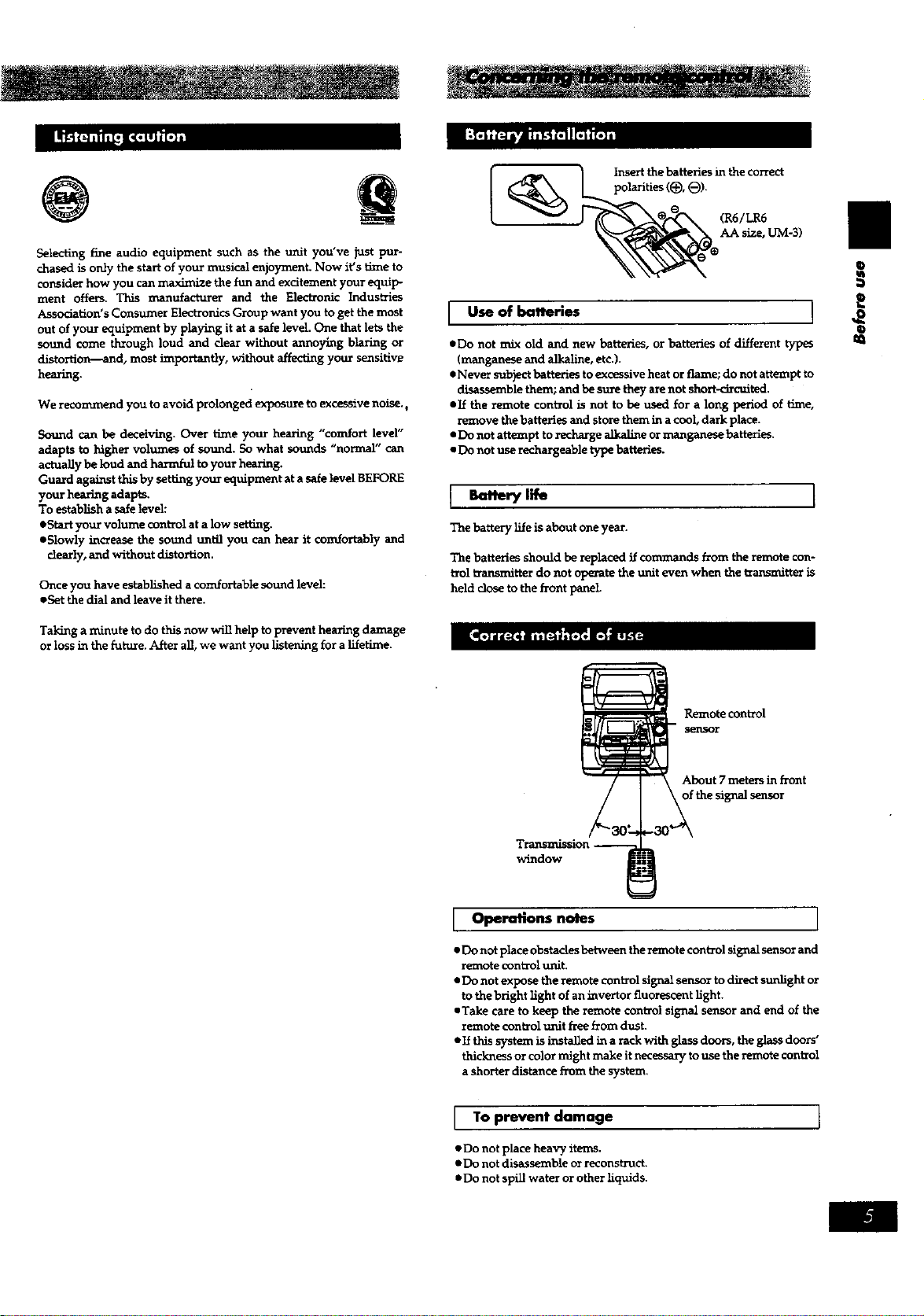
Insertthebatteriesinthecorrect
polarities((_,8).
(R6/LR6
AA size, UM-3)
I Use of batteries I
sDo not mix old and new batteries, or batteries of different types
(manganese and alkaline, etc.).
• Never subject batteries to excessive heat or flame; do not attempt to
disassemble them; and be sure they are not short-circuited.
elf the remote control is not to be used for a long period of time,
remove the batteries and store them in a cool dark place.
• Do not attempt to recharge alkaline or manganese batteries.
• Do not use zechargeable type batteries.
The battery life is about one year.
The batteries shouid be replaced if commands from the remote con-
trol transmitter do not operate the unit even when the transmitter is
held close to the front panel.
@
@
m
Taking a minute to do this now will help to prevent heating damage
or loss in the future. After all, we want you listening for a lifetime.
About 7meters in front
of thesignalsensor
window
I Operations notes I
• Do not place obstacles betwaen the remote conh'ol signal sensor and
remote control unit.
• Do not expose the remote control signal sensor to _ sunlight Or
to the bright light of an invertor fluor'_nt light.
•Take caretokeep the_mote controlsignalsensorand end ofthe
remotecontrolunitfreefromdust.
• If this system is installed in a rack with glass doors, the glass doors"
thickness or color might make it necessary to use the remote control
a shorter distance fTom the system.
I To prevent damage
• Do notplace heavy items.
• DO notdisassembleorreconstruct.
,,Do not spill water or other liquids.
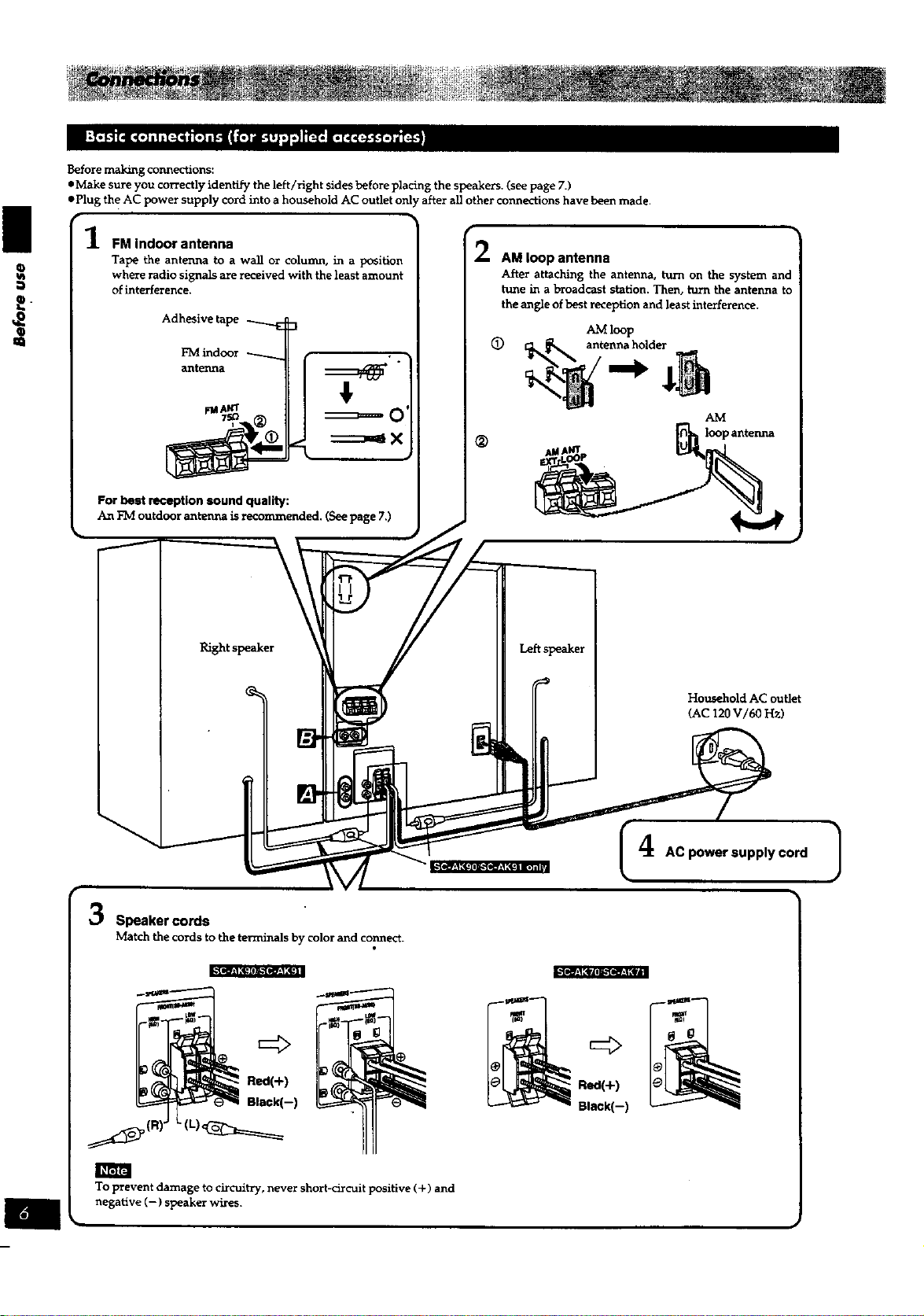
Before making connections:
eMake sure you correctly identify the left/rlght sides before placing the speakers. (see page 73
ePlug the AC power supply cord into a household AC outlet onl, after all other connections have been made.
|
FM indoor antenna
Tape the antenna to a wall or column, in a position
where radio signals are received with the least amount
of interference.
Adhesive tape _ :3
F'Mindoor
antenna _l _'_" " "
For best reception sound quality:
An FM outdoor antenna is recommended. (See page 7.)
Right speaker Left speaker
AM Ioop antenna
After attaching the antenna, turn on the system an(
bane in a broadcast station. Then, turn the antenna to
the angle of best reception and least interference.
O
@
AM loop
antannaholder
AM
loopantenna
Speaker cords
Matchthecords tothe terminalsbycolorandconnect.
Red(+)
Black(--)
Household AC outlet
(AC 120 V/60 Hz)
AC power supply cord
Red(+)
Black(--)
To preventdamage tocircuiri'y,nevershort_-'ircuitpositive(+)and
negative(- )speakerwires.
ra
Mamurd_(mduded)
(included) (included)
Surroundspeaker (Left) L_ Sunound speaker (Right)
(not included) _ (not included)
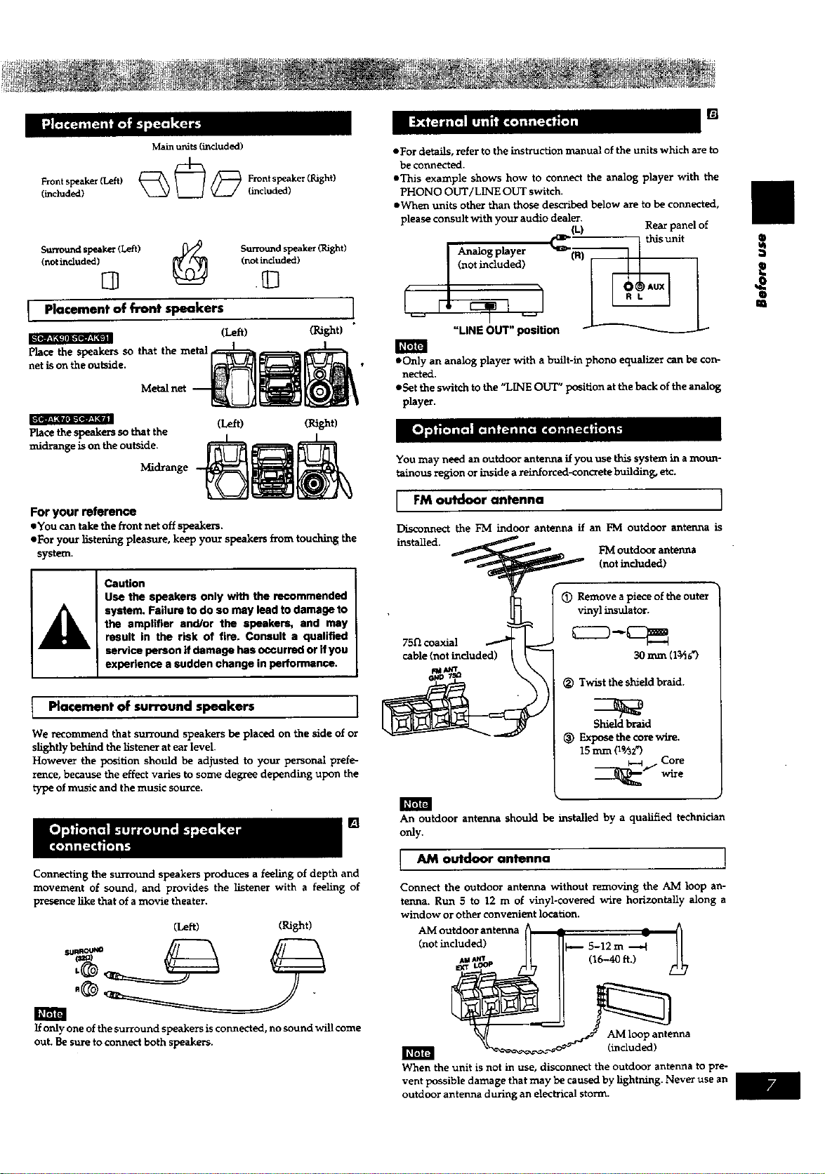
I Placement of front speakers I
(Left) (Right)
//
net is on the outside. ___ t
Place the speakersso that the
For your reference
eYou can take the #ont net oft speakers.
eFor your listening pleasure, keep your speakers from touching the
system.
Caution
Use the speakers only with the recommended
A system, Failure to do so may Iced to damage to
the amplifier and/or the speakers, and may
result in the risk of fire. Consult a qualified
service person if damage has occurred or If you
experience a sudden change in performance.
(Left) (P-.ight)
• For details, refer to the instruction manuel of the units which are to
be connected.
eThis example shows how to connect the analog player with the
PHONO OUT/LINE OUT switch.
eWhen units other than those described below are to be connected,
please consult with your audio dealer.
J Analog player _ "-------_ this unit
i (notincluded) _1 (R)_
"LINE OUT" position
• Only an analog player with abuilt-in phono equalizer can be con-
nected.
eSet the switch to the "LINE OUT" position at the back of the anelog
player.
You may need an outdoor antenila if you use this system in amoun-
tainous regionorinsideareinforced-concretebuilding,etc.
I FM ouh:ioor antenna 1
Disconnectthe FM indoor antenna ifan FM outdoor antenna is
instalied.
75fi coaxial
cable (not included)
(L) Rear panel of
FM outdoorantenna
(not induded)
) Remove a piece of the outer
vinyl insulator.
Twistthe shieldbraid.
t Placement of surround speclkers I
We recommend thatsurround speakersbe placedon thesideofor
slightlybehindthelisteneratearlevel.
However the positionshould be adjustedto your personalprefe-
rence,becausetheeffectvariestosome degreedepending upon the
typeofmusicand themusic source.
[]
Connectingthesurround speakersproducesa feelingofdepth and
movement of sound, and providesthe listenerwith a feelingof
presencelikethatofa movie theater.
(Left) (Right)
t___)
If only one of the surround speakers is connected, no sound will come
out. Be sure to connect both speakers.
Shieldbraid
(_ Expose thecorewire.
15mm 0%2")
An outdoor antenna should be installed by a qualified technician
only.
Core
f" wire
I AM outdoor antenna
Connect the outdoor antenna without removing the AM loop an-
tenna. Run 5 to 12 m of vinyl-covered wire horizontally along a
window or other convenient location.
When the unit is not in use, disconnect the outdoor antenna to pre-
vent possible damage that may be caused by lightmng, Never use an _
outdoor antenna during an electrical storm.
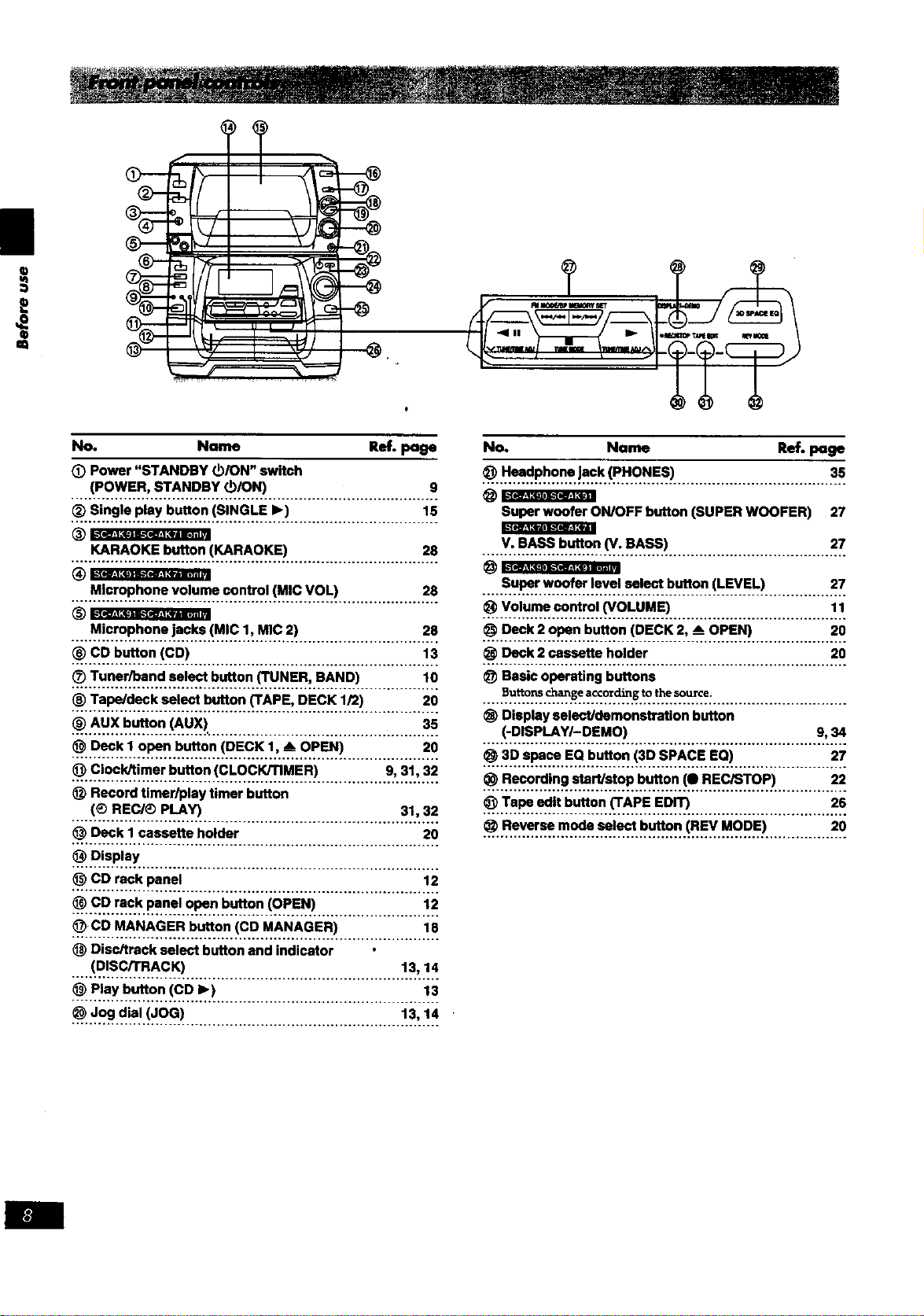
No. Name Ref. page
(T) Power "STANDBY _/ON" switch
(POWER, STANDBY (_/ON) 9
(_ Single play button (SINGLE I_) 15
(_ -'-" _*L •
KARAOKE button (KARAOKE) 28
No. Name Ref. page
_) Headphone Jack(PHONES) 35
Super woofer ON/OFF button (SUPER WOOFER) 27
Ik,'l"_ ] _rlllk'!lll I 4rJ
V. BASS button (V. BASS) 27
Microphone volume control (MIC VOL) 28
Microphone jacks (MIC 1, MIC 2) 28
CD button (CD) 13
(_ Tuner/band select button (TUNER, BAND) 10
Tape/deck select button (TAPE, DECK 1/2) 20
.................................................35
Deck I open button (DECK t, ---_OPEN) 20
_) Clock/timer button (CLOCK/TIMER) 9, 31, 32
Record timer/play timer button
(_ REC/_ PLAY) 31, 32
Deck I cassette holder 20
....................................................................
_) CD rack panel 12
CD rack penei open button (OPEN) 12
CD MANAGER button (CD MANAGER) 18
_) Disc/track select button and indicator
(DiSCrrRACK) 13,14
Play button (CD I_) 13
Jog dial (JOG) 13, 14
Super woofer level select button (LEVEL) 27
Volume control (VOLUME) 11
_) Deck 2 open button (DECK 2, _--OPEN) 20
Deck 2 cassette holder 20
_) Basic operating buttons
Buttonscha-ngeaccordingtothesource.
Display select/demonstration button
(-DISPLAW-DEMO) 9, 34
_) 3D space EQ button (3D SPACE EQ) 27
Tape edit button (TAPE EDIT) 26
_) Reverse moda select button (REV MODE) 20
F:]
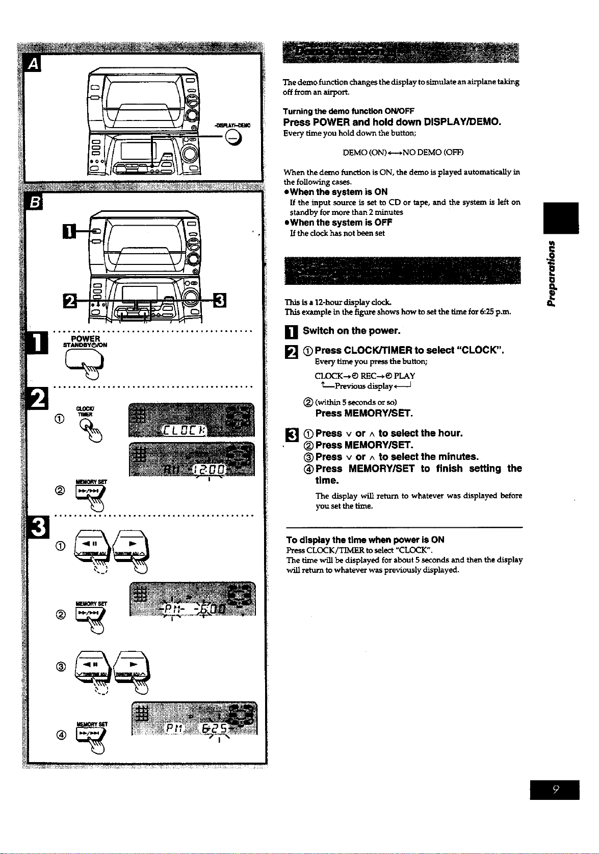
Thedemo function changesthedisplay tosimulataan airplane taking
off from an an-port
Turningthe demofunction ON/OFF
Press POWER and hold down DISPLAY/DEMO.
Every time you hold down thebutton;
DEMO (ON)_--+NO D_O (OFF)
When the demo function is ON, the demo is played automatically in
the following cases.
eWhen the system is ON
If the input source is set to CD or tape, and the system is left on
standby for more than 2 minutes
eWhen the system is OFF
If the clock has not been set
This is a 12-hour display dock.
This example in the figure shows how toset the time for 6:25p.m.
.._ ......... ..................°..
%
[] Switch on the
[] O Press CLOCK/TIMER to select "CLOCK".
Every time you pr--,:_sthe button;
CLOCK---*_ REC---*_ PLAY
L--Previous display (----I
(_) (_rlthi_t5 seconds or so)
Press MEMORY/SET.
power.
[] (_)Press v or ^ to select the hour.
• _) Press MEMORY/SET.
(__)Pressv or ^ to select the minutes.
_)Press MEMORY/SET to finish setting the
time.
The display will reVarn to whatever was displayed before
you set the time.
To display the time when power is ON
Press CLOCK/_ to select "CLOCK".
The time will be displayed for about 5 seconds and then the display
will return to whatever was previously displayed.
|
i
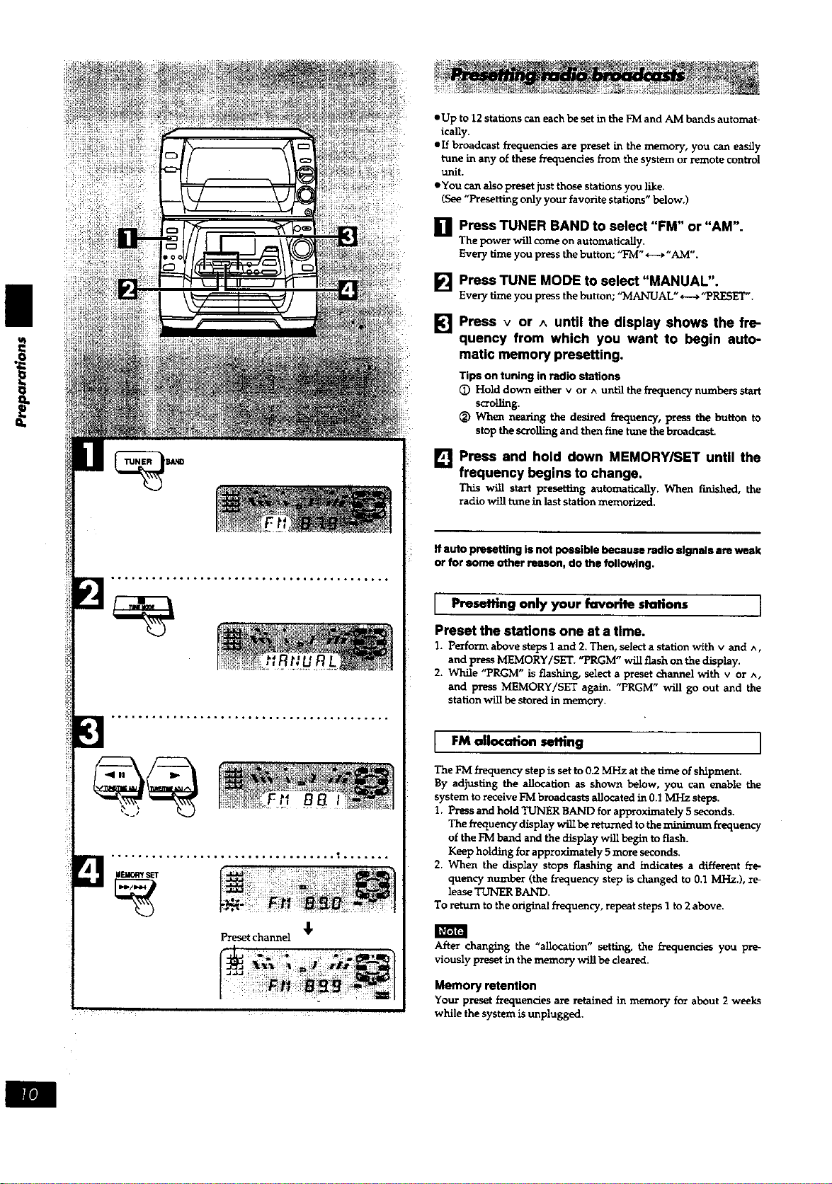
SUp to12stationscaneachbe setintheFM and AM bands automat-
ically.
elfbroadcastfrequenciesare pz_setinthememory, you can easily
tuneinany ofthesefrequenciesfrom thesystemorremotecontrol
unit.
eYou can alsopresetjustthosestationsyoulike.
(See"Presettingonlyyour favoritestations"below.)
Press TUNER BAND to select "FM" or "AM".
The power willcome on automatically.
Everytimeyou pressthebutton;"FM" _ "AM".
Press TUNE MODE to select "MANUAL".
Every time you press the button; "MANUAL"<--._. "PRESET".
[] Press v or ^ until the display shows the fre-
quency from which you want to begin auto-
matic memory presetting.
Tips on tuning in radio stations
(_) Hold down either v or ^ until the frequency numbers start
sc_oRing.
_) When nearingthe d_ frequency,pressthe button to
stop the scrolling and then fine ttme the broadcast.
Press and hold down MEMORY/SET until the
[]
frequency begins to change.
This willstartpresettingautomatically.When finished,the
radiowilltuneinlaststationmemorized.
..... .......... ..,...... ......... t. ......
Presetchannel
If auto presetting is not possible because radio signals are weak
or for some other reason, do the following.
[ Presetting only your favorite stations ]
Preset the stations one at a time.
1.. Perform above stel_ 1 and 2. Then, select a station with v and ^,
and press MEMORY/SET. "PRGM" will flash on the display.
2. While "PRGM" is flashing, select a preset chmlnel with v or ^,
and press MEMORY/SET again. "PRGM" will go out and the
station will be stored in memory.
FM allocation setting ]
The FM f_quency step is set to 0.2 MHz at the time of shipment.
By adjusting the allocation as shown below, you can enable the
systemtoreceiveFM broadcastsallocatedin0.1MHz steps.
1.Pressand holdTUNER BAND forapproximately5 seconds.
The f_quency display will be returned to the minimum frequency
of the FM band and the display will begin to flash.
Keep holding for approximately 5 more seconds.
2. When the display stops flashing and indicates a diffe_nt fre-
quency number (the frequency step is changed to 0.1 MHz.), re-
lease TUNER BAND.
To return to the original frequency, repeat steps 1 to 2 above.
Afterchanging the "allocation"setting,the frequenciesyou pre-
viouslypresetinthememory willbe cleared.
Memory retention
Your p_set frequencies are _tained in memory for about 2 weeks
while the system is unplugged.
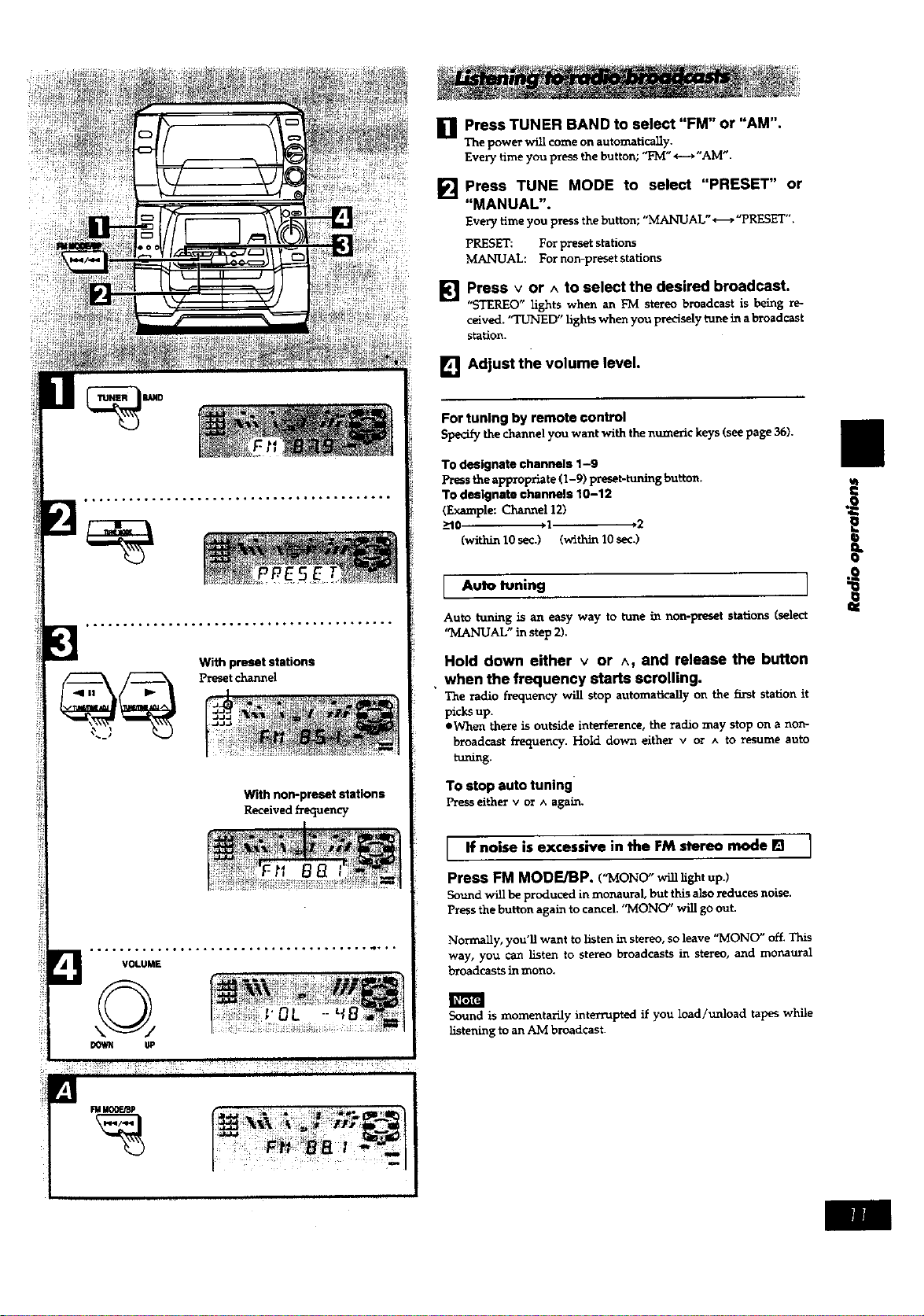
E] Press TUNER BAND to select "FM" or "AM".
The power will come on automatically.
Every time you press the button; "FM" <---.*"AM".
[] Press TUNE MODE to select "PRESET" or
"MANUAL".
Everytimeyou pressthebutton; "MANUAL",-----> "PRESET".
PRESET: For preset stations
MANUAL: For non-preset stations
_ Press v, or ^ to select the desired broadcast.
"STEREO lights when anFM stereobroadcastisbeing_e-
ceived. "TUNED" lights when you precisely tune in a broadcast
station.
[] Adjust the volume level.
For tuning by remote control
Specify the channel you want with the numeric keys (see page 36). m
TO designate channels 1-9
Fresstheappropriate(1-9)preset-toningbutton.
To designate channels 10-12
(Example: Channel 12)
->10 -.I -,2
(within 10 sec.) (within10 sec.)
i
• ..... •.•.. .... ......°,.••.. ..... ••......
With preset stations
With non-preset stations
Received frequency
[ Autohining ] i
Auto tuning is an easy way to tune in non-presetstations(select
"MANUAL" instep2).
Hold down either v or ^, and release the button
when the frequency starts scrolling.
The radiofrequencywillstopautomaticallyon thefirststationit
picksup.
eWhen there is outside interference, the radio may stop on a non-
broadcastfrequency.Hold down eitherv or ^ toresumeauto
tuning.
To stop auto tuning
Presseither v or ^ again.
If noise is excessive in the FM stereo mode [] I
Press FM MODE/BP. ("MONO" willlightup.)
Sound will be produced in monaural, but this also reduces noise.
Press the button again to cancel. "MONCY' will go out.
Normally, you IIwant to listen m stereo, so leave MONO' off. Th
way, you can listen to stereo broadcasts in stereo, and monaural
broadcasts in mono.
Sound is momentarily interrupted if you load/unload tapes while
listening to an AM broadcast.
• ' " " ' is

You can setCDs m the rack and remove them too, while playing CDs.
I How to CDs
remove
|
i
I How to set CDs
1. Open the rack panel.
Except when _g or removing CI_, keep hands out of the changer
while open. You could injure yourself if somehow entangled in the
internal mechanism.
2. Slide the loader carriage to the slot you want.
The loadercarnagehas a LOCK position(when the leveris
down) and a RELEASE position(whentheleverisup).When you
slidetheloadercarriagetoselecttheslotyou want, make sureit
isintheRELEASE position(when theleverisup).
You can readthenumbers between theprongsasshown below.
Slot
number
1. Open the rack panel.
2. Slide the loader carriage to the slot you want•
Do notslidetheloadercarriagewhen theleverisdown.
3. Lower the end of the lever and then remove CDs.
How to know whut CD is in what slot ]
Thissystem comes with a notebook-likebinder(linernotesorga-
nizer)inwhich you cankeepyourCD liners.Therearealsoadhesive
ntunbersforindicatingslotnumbers in thebinder.Thisisa conve-
nientway tokeeptrackofwhat CD isinwhat slot.
Adhesive Pocket
8
•Loadercarriage
I Slot No. 0 (SINGLE) is reserved for CD [
3•
(_ Lower the lever on the loader carriage and set
the CD in the groove with the label facing to
the right.
(_ Raise the lever.
Label side
4.
Close the rack panel gently.
You willhearacatchingsound when therackpanelcloses.
single play (p.
Raise the lever.
PX_SSon
centerpiece,
15).
Put two linershack-to-beckinsideeachpocket,asshown above.
Do notput CD cases in the binder.
I
To prevent damage ]
Always observethefollowing points.
• Never loadmore thanone CD inanygivenslot.
•Do notuse 3"(8cm) CDs fittedwithexpanderrings.
•Do notPot anythingotherthanCDs inthechanger.
• Do notsetaCD intheslotoftheCD beingplayed(slotflashes).
#Sometimes therackpanelcannotbe opened whilea CD isplaying.
Itisaquestionoftime.Insuchcase,waituntilyou canopen it.
•Do notopen tharackpanelwhilethechangerischangingCDs.
•Do not use cleaningCDs or CDs which are badly warped or
cracked.
• Set the system on a fiat, level surface.
DO not set it on top of magazines, inclined surfaces, etc.
•Always unload all CDs before moving the system.
•Do notuseCDs with poorlyattachedlabelsorstickers.
Adhesive protrudingfrom underneath stickersor leftover from
peeledoffstickerscan causethesystemtomalfunction.
eDo notuseirregularshape CDs (heart-shape,octagonal,etc.).
x@ xQ
 Loading...