

Panasonic SL-NE5EF, SL-NE5EG, SB-NE5EF, SB-NE5EG, SC-NE5EF Service manual
...
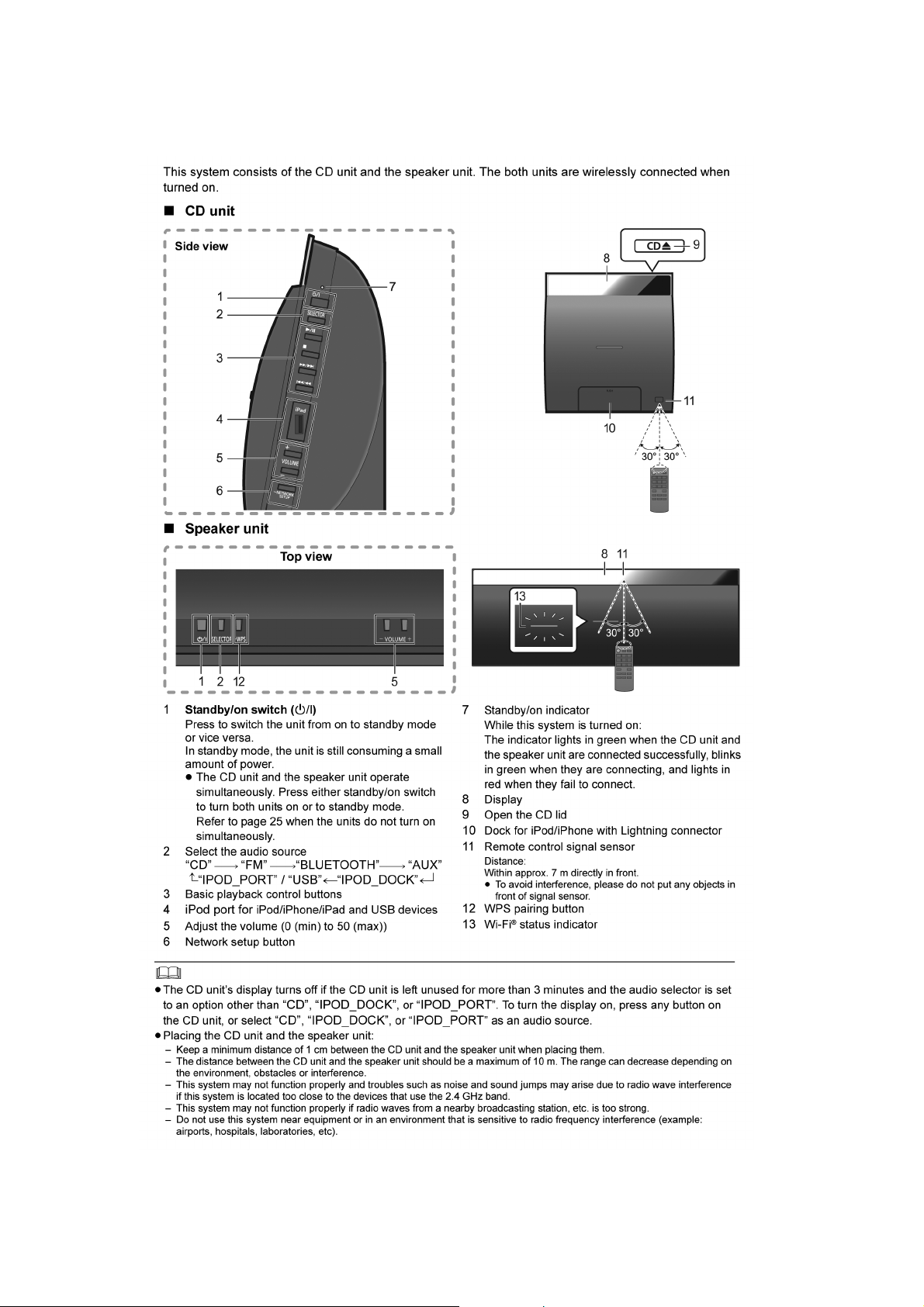
Wireless Speaker System
Model No. SL-NE5EF
SL-NE5EG
SB-NE5EF
SB-NE5EG
SC-NE5EF
SC-NE5EG
Product Color: (K)...Black Type
PSG1303005CE
TABLE OF CONTENTS
1 Safety Precautions----------------------------------------------- 3
1.1. General Guidelines---------------------------------------- 3
1.2. Before Repair and Adjustment ------------------------- 4
1.3. Protection Circuitry---------------------------------------- 4
1.4. Caution For Fuse Replacement ------------------------ 4
1.5. Safety Part Information----------------- --------- --------- 5
2 Warning-------------------------------------------------------------- 6
2.1. Prevention of Electrostatic Discharge (ESD)
to Electrostatically Sensitive (ES) Devices---------- 6
2.2. Precaution of Laser Diode (SL-NE5) ----------------- 7
2.3. Service caution based on Legal restrictions--------8
2.4. Handling Precaution for Traverse Assembly ------- 9
3 Service Navigation----------------------------------------------10
3.1. Service Information --------------------------------------10
3.2. Troubleshooting Guide----------------------------------11
PAGE PAGE
4 Specifications ----------------------------------------------------12
4.1. License ----------------------------------------------------- 13
5 General/Introduction-------------------------------------------14
5.1. Using AirPlay with this system’s speakers---------14
5.2. Playing back music files on the DLNA server----- 15
5.3. Bluetooth® Operations --------------------------------- 16
5.4. Playable media -------------------------------------------17
6 Location of Controls and Components------------------ 18
6.1. Main Unit Key Button Operations-------------------- 18
6.2. Remote Control Key Button Operations------------ 19
7 Installation Instructions -------------------------------------- 20
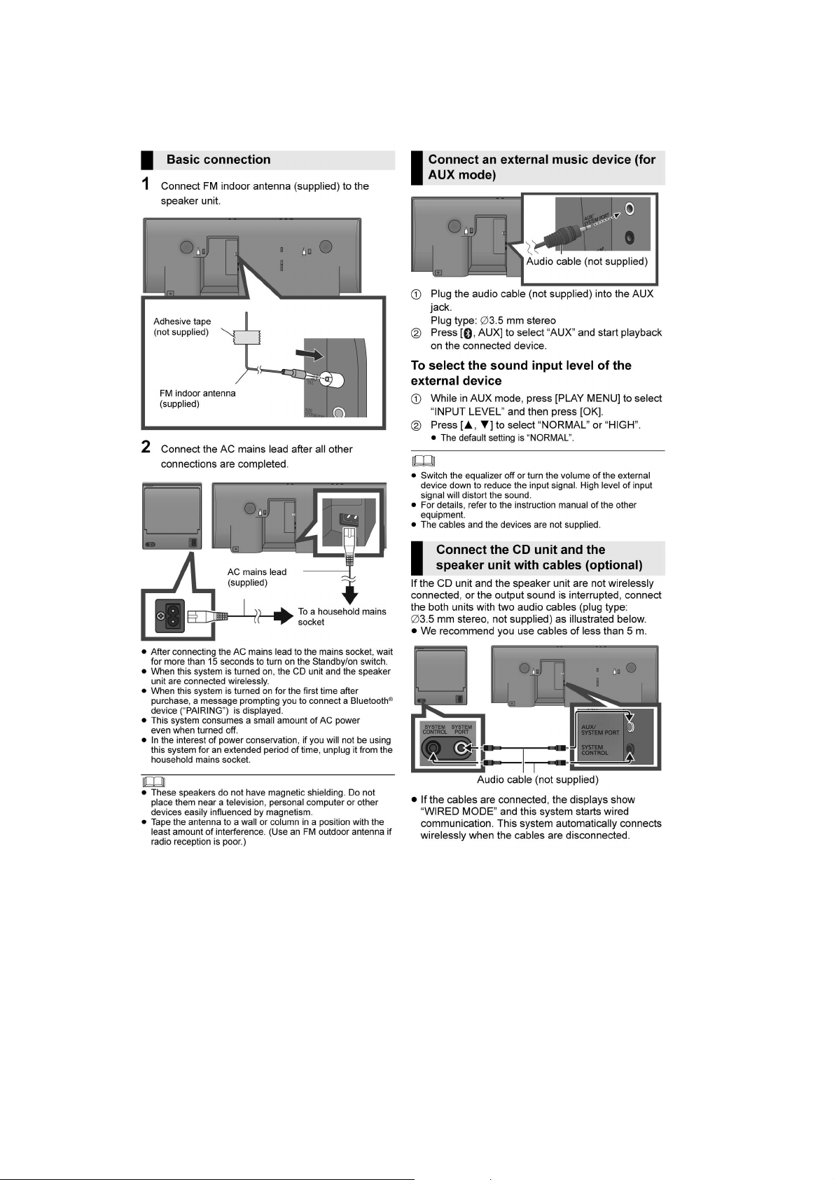
7.1. Connections----------------------------------------------- 20
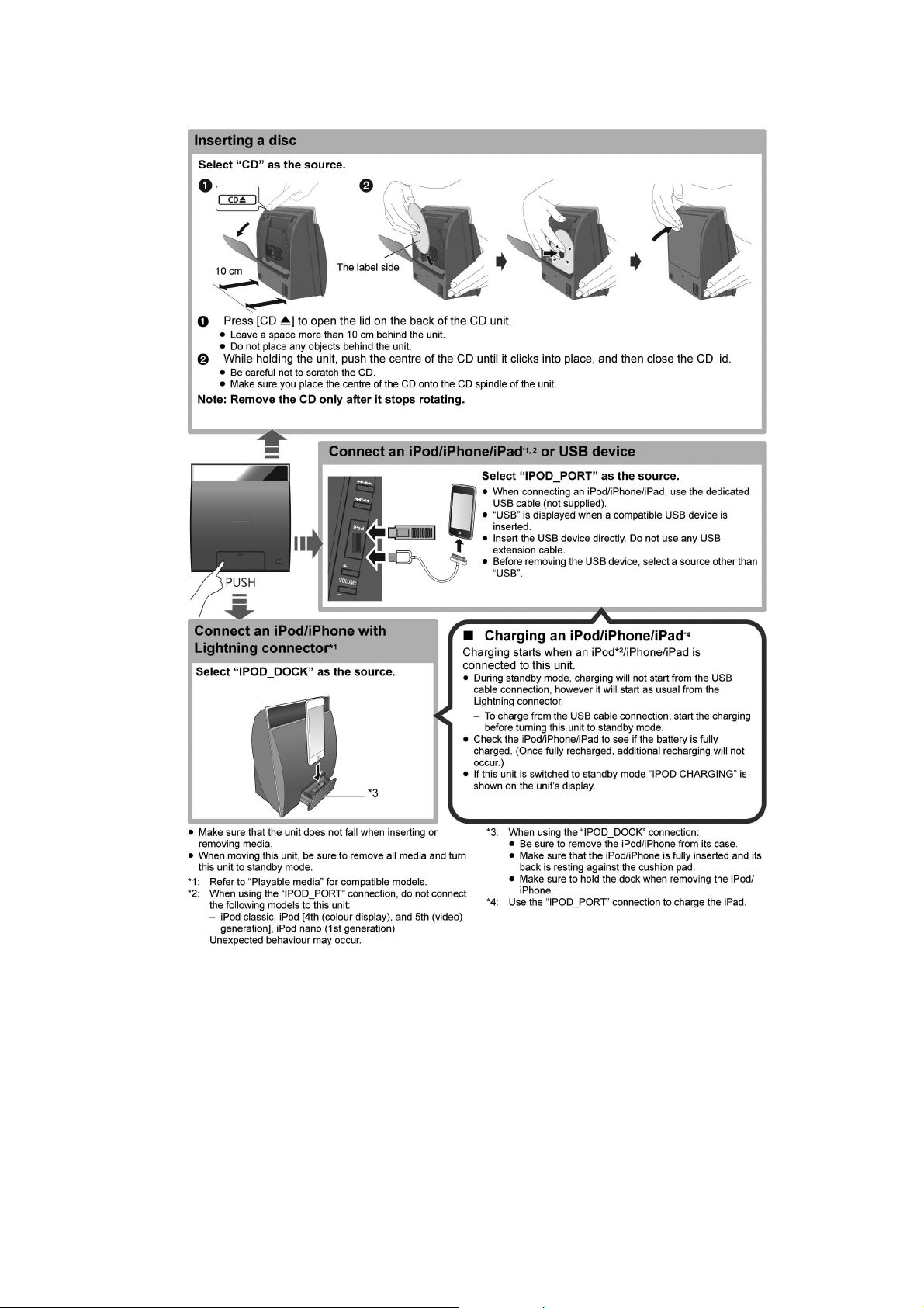
7.2. Inserting media -------------------------------------------21
7.3. Network settings------------------------------------------22
8 Service Mode ----------------------------------------------------- 25
© Panasonic Corporation 2013. All rights reserved.
Unauthorized copying and distribution is a violation of
law.

8.1. Self Diagnostic Mode------------------------------------ 25
8.2. Self Diagnostic Function Error Code----------------26
8.3. Doctor Mode Table (SB-NE5)-------------------------27
8.4. Doctor Mode Table (SL-NE5) -------------------------31
9 Service Fixture & Tools (SL-NE5)--------------------------35
10 Disassembly and Assembly Instructions (SL-
NE5)------------------------------------------------------------------36
10.1. Disassembly flow chart ---------------------------------37
10.2. Types of Screws------------------------------------------37
10.3. Main Parts Location Diagram -------------------------38
10.4. Disassembly of Rear Cabinet Assy------------------39
10.5. Disassembly of Button P.C.B.-------------------------40
10.6. Disassembly of Interlock Switch P.C.B.------------- 41
10.7. Disassembly of CD Lid---------------------------------- 42
10.8. Disassembly of Aux P.C.B. ----------------------------45
10.9. Disassembly of Panel P.C.B.--------------------------46
10.10. Disassembly of SMPS P.C.B.-------------------------47
10.1 1 . Disassembly of CD Mechanism ----------------------48
10.12. Disassembly of CD Servo P.C.B.---------------------49
10.13. Disassembly of Main P.C.B. ---------------------------51
10.14. Disassembly of Bluetooth Module P.C.B. ----------52
10.15. Disassembly of iPod Unit ------------------------------53
10.16. Replacement of iPod P.C.B. and iPod
Connector Unit--------------------------------------------55
11 Service Position (SL-NE5)------------------------------------62
11.1. Checking of Panel P.C.B. ------------------------------62
11.2. Checking of SMPS P.C.B.------------------------------ 62
11.3. Checking of Main P.C.B. (Side A and B) -----------63
11.4. Checking of CD Servo P.C.B.-------------------------64
12 Service Fixture & Tools (SB-NE5) -------------------------65
13 Disassembly and Assembly Instructions (SB-
NE5)------------------------------------------------------------------66
13.1. Disassembly flow chart ---------------------------------67
13.2. Types of Screws------------------------------------------67
13.3. Main Parts Location Diagram -------------------------68
13.4. Disassembly of Inne r Cover Unit---------------------69
13.5. Disassembly of SPK LED P.C.B.---------------------70
13.6. Disassembly of SPK AirPlay Module P.C.B.
and SPK AirPlay Connect P.C.B.---------------------71
13.7. Disassembly of SPK AirPlay Antenna P.C.B.-----72
13.8. Disassembly of SPK Bluetooth Module P.C.B. ---73
13.9. Disassembly of SPK SMPS P. C.B. ------------------74
13.10. Replacement of Diode (D1700) ----------------------76
13.11. Replacement of Switching Regulator IC
(IC1700) ----------------------------------------------------77
13.12. Disassembly of SPK Main P. C.B. --------------------79
13.13. Disassembly of Front Panel Block-------------------81
13.14. Disassembly of SPK Panel P.C.B.-------------------82
13.15. Disassembly of Front Speaker (SP1 and SP2)---83
13.16. Disassembly of Tweeter Speaker (SP3 and
SP4) ---------------------------------------------------------84
14 Service Position (SB-NE5) -----------------------------------85
14.1. Checking of SPK AirPlay Connect P.C.B.----------85
14.2. Checking of SPK SMPS P.C.B.-----------------------85
14.3. Checking of SPK Main P.C.B. (Side B)-------------86
14.4. Checking of SPK Main P.C.B. (Side A)-------------86
14.5. Checking of SPK Panel P.C.B.------------------------ 87
15 Block Diagram ---------------------------------------------------89
15.1. Servo, System Control and Audio (SL-NE5) ------89
15.2. IC Terminal Chart (SL-NE5)---------------------------91
15.3. Power Supply (SL-NE5)--------------------------------92
15.4. System Control (SB-NE5)----------------------------- 94
15.5. Audio (SB-NE5)------------------------------------------ 95
15.6. Power Supply (SB-NE5)------------------------------- 96
16 Wiring Connection Diagram -------------------------------- 98
16.1. Main Unit (SL-NE5) ------------------------------------- 98
16.2. Speaker Unit (SB-NE5) -------------------------------- 99
17 Schematic Diagram-------------------------------------------101
17.1. Schematic Diagram Notes ---------------------------101
17.2. CD Servo Circuit (SL-NE5)---------------------------103
17.3. Main (Diginet/Micon/USB) Circuit (SL-NE5)-----105
17.4. iPod, AUX and Panel Circuit (SL-NE5) -----------110
17.5. Button and Interlock Switch Circuit (SL-NE5) --- 111
17.6. SMPS Circuit (SL-NE5) ------------------------------- 112
17.7. SPK Main (Diginet/Micon/Damp) Circuit (SBNE5)--------------------------------------------------------113
17.8. SPK Panel, AirPlay Antenna and SPK LED
Circuit (SB-NE5) ----------------------------------------120
17.9. SPK SMPS Circuit (SB-NE5)------------------------121
17.10. SPK AirPlay Connect Circuit (SB-NE5)-----------122
18 Printed Circuit Board-----------------------------------------123
18.1. CD Servo P.C.B. (SL-NE5)---------------------------123
18.2. Main P.C.B. (SL-NE5) ---------------------------------124
18.3. iPod, AUX and Panel P.C.B. (SL-NE5)------------126
18.4. Button, Interlock Switch and SMPS P.C.B.
(SL-NE5)--------------------------------------------------127
18.5. SPK Main P.C.B. (SB-NE5) --------------------------128
18.6. SPK Panel, SPK AirPlay Antenna and SPK
LED P.C.B. (SB-NE5)----------------------------------129
18.7. SPK SMPS and SPK AirPlay Connect P.C.B.
(SB-NE5)--------------------------------------------------130
19 Appendix Information of Schematic Diagram -------131
19.1. Voltage Measurement and Waveform Chart
(SL-NE5)--------------------------------------------------131
19.2. Voltage Measurement and Waveform Chart
(SB-NE5)--------------------------------------------------136
19.3. Waveform Chart-----------------------------------------139
20 Exploded View and Replacement Parts List----------141
20.1. Exploded View and Mechanical replacement
Parts List--------------------------------------------------141
20.2. Electrical Replacement Parts List ------------------148
2
1 Safety Precautions
1.1. General Guidelines
1. IMPORTANT SAFETY NOTICE
There are special components used in this equipment which a re important for safety. These parts are marked by in the
Schematic Diagrams, Circuit Board Layout, Exploded Views and Replacement Parts List. It is essential that these critical parts
should be replaced with manufacturer’s specified parts to prevent X-RADIATION, shock, fire, or other hazards. Do not modify
the original design without permission of manufacturer.
2. An Isolation Transformer should always be used during the servicing of AC Adaptor whose chassis is not isolated from the AC
power line. Use a transformer of adequate power rating as this protects the technician from accidents resulting in personal
injury from electrical shocks. It will also protect AC Adaptor from being damaged by accidental shorting that may occur during
servicing.
3. Wh en servicing, observe the original lead dress. If a short circuit is found, replace all parts which have been overheated or
damaged by the short circuit.
4. After servicing, see to it that all the protective devices such as insulation barriers, insulation papers shields are properly
installed.
5. After servicing, make the following leakage current checks to prevent the customer from being exposed to shock hazards.
1.1.1. Leakage Current Cold Check
1. Unplug the AC cord and connect a jumper between the two prongs on the plug.
2. measure the resistance value, with an ohmmeter between the jumpered AC plug and e ach exposed metallic cabinet part on
the equipment such as screwheads, connectors, control shafts, etc. When the exposed metallic part has a return path to the
chassis, the reading should be between 1MΩ and 5.2MΩ. When the exposed me tal does not have a retu rn path to the chas-
sis, the reading must be
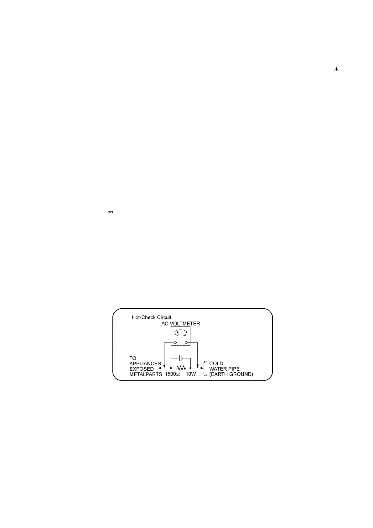
1.1.2. Leakage Current Hot Check
1. Plug the AC cord directly into the AC outlet. Do not use an isolation transformer for this check.
2. Connect a 1.5kΩ, 10 watts resistor, in parallel with a 0.15µF capacitors, between each exposed metallic part on the set and a
good earth ground such as a water pipe, as shown in Figure 1-1.
3. Use an AC voltmeter, with 1000 ohms/volt or more sensitivity, to measure the potential across the resistor.
4. Check each exposed metallic part, and measure the voltage at each point.
5. Reverse the AC plug in the AC outlet and repeat each of the above measurements.
6. Th e potential at any point should not exceed 0.75 volts RMS. A leakage current tester (Simpson Model 229 or equivalent)
may be used to make the hot checks, leakage current must not exceed 1/2 milliamp. In case a measurement is outside of the
limits specified, there is a possibility of a shock hazard, and the equipment should be repaired and rechecked before it is
returned to the customer.
Figure 1-1
3
1.2. Before Repair and Adjustment
SL-NE5
Disconnect AC power to discharge unit AC Capacitors (C1001, C100 3, C1005, C1006 and C1018 ) through a 10W, 1W resistor to
ground.
SB-NE5
Disconnect AC power to discharge unit AC Capacitors (C1702, C171 0, C1725, C1727 and C1728 ) through a 10W, 1W resistor to
ground.
Caution:
DO NOT SHORT-CIRCUIT DIRECTLY (with a screwdriver blade, for instance), as this may destroy solid state devices.
After repairs are completed, restore power gradually using a variac, to avoid overcurrent.
• Current consumption at AC 240V, at 50Hz in NO SIGNAL mode at volume min should be ~200 mA.
1.3. Protection Circuitry
The protection circuitry may have operated if either of the following conditions are noticed:
• No sound is heard when the power is turned on.
• Sound stops during a performance.
The function of this circuitry is to prevent circuitry damage if, for example, the positive and negative speaker connection wires are
"shorted", or if speaker systems with an impedance less than the indicated rated impedance of the amplifier are used.
If this occurs, follow the procedure outlines below:
1. Turn off the power.
2. Determine the cause of the problem and correct it.
3. Turn on the power once again after one minute.
Note:
When the protection circuitry functions, the unit will not operate unless the power is first turned off and then on again.
1.4. Caution For Fuse Replacement
4
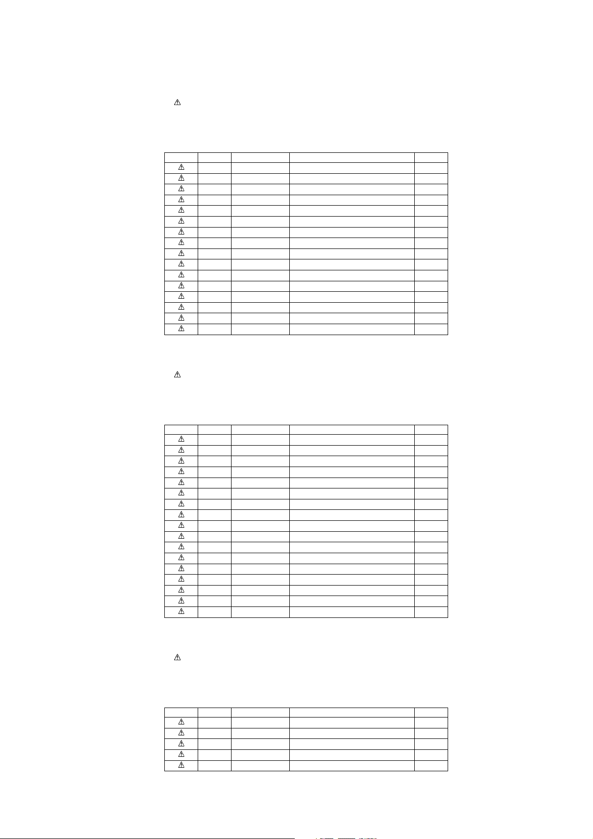
1.5. Safety Part Information
1.5.1. Safety Parts List (SL-NE5):
There are special components used in this equipment which are important for safety.
These parts are marked by in the Schematic Diagrams, Exploded View & Replacement Parts List. It is essential that these
critical parts should be replaced with manufacturer’s specified parts to prevent shock, fire or other hazards. Do not modify the
original design without permission of manufacturer.
Safety Ref No. Part No. Part Name & Description Remarks
24 RFKHLNE5EG-K CD REAR CABINET ASS'Y
301 RAE5301Z-V TRAVERSE
PCB5 REP4847CA SMPS P.C.B. (RTL)
L1001 G0B233D00005 LINE FILTER
T1001 G4DYA0000463 TRANSFORMER
Z1001 D4EAY471A127 VARISTOR
PC1022 B3PBA0000503 PHOTO COUPLER
F1 K5G202Y00006 FUSE
P1001 K2AA2B000011 AC INLET
R1006 ERJ8GEYJ155V 1.5M 1/4W
R1007 ERJ8GEYJ155V 1.5M 1/4W
C1001 F0CAF104A105 0.1uF
C1003 F0CAF104A105 0.1uF
C1005 F1BAF1020020 1000pF
C1006 F1BAF1020020 1000pF
C1018 F1BAF471A013 470pF
1.5.2. Safety Parts List (SB-NE5):
There are special components used in this equipment which are important for safety.
These parts are marked by in the Schematic Diagrams, Exploded View & Replacement Parts List. It is essential that these
critical parts should be replaced with manufacturer’s specified parts to prevent shock, fire or other hazards. Do not modify the
original design without permission of manufacturer.
Safety Ref No. Part No. Part Name & Description Remarks
69 RFKHCNE5EG-K SPEAKER REAR CABINET ASS'Y
87 RMV0390 SMPS INSULATOR SHEET A
88 RMV0391-1 SMPS INSULATOR SHEET B
PCB5 REP4848F SPK SMPS P.C.B. (RTL)
L1702 G0B183E00004 LINE FILTER
T1700 G4DYZ0000059 TRANSFORMER
Z1752 ERZE08A471CS VARISTOR
PC1701 B3PBA0000503 PHOTO COUPLER
F1 K5G202Y00006 FUSE
P1751 K2AA2B000011 AC INLET
R1724 ERJ12YJ105U 1M 1/2W
R1726 ERJ12YJ105U 1M 1/2W
C1702 F0CAF224A105 0.22uF
C1710 F1BAF471A013 470pF
C1725 F0CAF154A105 0.15uF
C1727 F1BAF1020020 1000pF
C1728 F1BAF1020020 1000pF
1.5.3. Safety Parts List (SC-NE5):
There are special components used in this equipment which are important for safety.
These parts are marked by in the Schematic Diagrams, Exploded View & Replacement Parts List. It is essential that these
critical parts should be replaced with manufacturer’s specified parts to prevent shock, fire or other hazards. Do not modify the
original design without permission of manufacturer.
Safety Ref No. Part No. Part Name & Description Remarks
A1 N2QAYC000090 REMOTE CONTROL
A2 K2CQ2YY00119 AC CORD
A3 VQT4U58-1 O/I BOOK (Ge/Fr/It/Du)
A3 VQT4U59-1 O/I BOOK (Sp/Sw/Da/Fi) EG
A3 VQT4U60-1 O/I BOOK (En/Po/Cz) EG
5
2Warning
2.1. Prevention of Electrostatic Discharge (ESD) to Electrostatically Sensi-
tive (ES) Devices
Some semiconductor (solid state) devices can be damaged easily by static electricity. Such components commonly are called Electrostatically Sensitive (ES) Devices.
The following techniques should be used to help reduce the incidence of component damag e caused by electrostatic discharge
(ESD).
1. Immediately before handling any semiconductor component or semiconductor-equipped assembly, drain off any ESD on your
body by touching a known earth ground. Alternatively, obtain and wear a commercially available discharging ESD wrist strap,
which should be removed for potential shock reasons prior to applying power to the unit under test.
2. After removing an electrical assembly equipped with ES devices, p lace the assembly on a cond ucti ve surface su ch as a lumi-
num foil, to prevent electrostatic charge buildup or exposure of the assembly.
3. Use only a grounded-tip soldering iron to solder or unsolder ES devices.
4. Use only an anti-static solder removal device. Some solder removal devices not classified as “anti-static (ESD protected)” can
generate electrical charge sufficient to damage ES devices.
5. Do not use freon-propelled chemicals. These can generate electrical charges sufficient to damage ES devices.
6. Do not remove a replacement ES device from its protective package until immediately before you are ready to install it. (Most
replacement ES devices are packaged with leads electrically shorted together by conductive foam, aluminum foil or comparable conductive material).
7. Immediately before removing the protective material from the leads of a replacement ES device, touch the protective material
to the chassis or circuit assembly into which the device will be installed.
CAUTION:
Be sure no power is applied to the chassis or circuit, and observe all other safety precautions.
8. Minimize bodily motions when handling unpackaged replacement ES devices. (Otherwise harmless motion such as the
brushing together of your clothes fabric or the lif ting of your foot from a carpeted floor can generate static electricity (ESD) sufficient to damage an ES device).
6
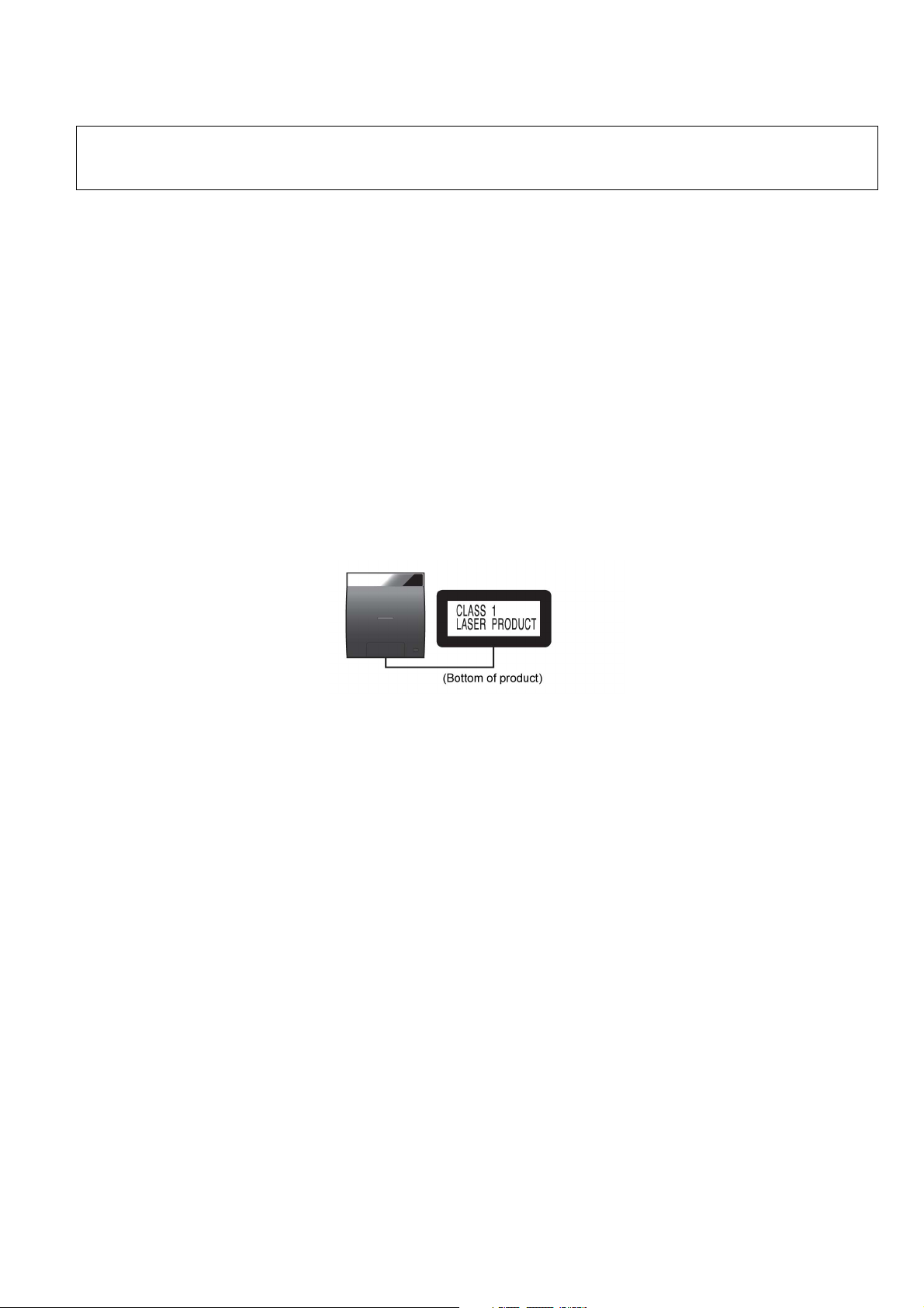
2.2. Precaution of Laser Diode (SL-NE5)
CAUTION!
THIS PRODUCT UTILIZES A LASER.
USE OF CONTROLS OR ADJUSTMENTS OR PERFORMANCE OF PROCEDURES OTHER THAN THOSE SPECIFIED HEREIN MAY RESULT
IN HAZARDOUS RADIATION EXPOSURE.
Caution:
This product utilizes a laser diode with the unit turned "on", invisible laser radiation is emitted from the pickup le ns.
Wavelength: 790 nm (CD)
Maximum output radiation power from pickup: 100 µW/VDE
Laser radiation from the pickup unit is safety level, but be sure the followings:
1. Do not disassemble the pickup unit, since radiation from exposed laser diode is dangerous.
2. Do not adjust the variable resistor on the pickup unit. It was already adjusted.
3. Do not look at the focus lens using optical instruments.
4. Recommend not to look at pickup lens for a long time.
ACHTUNG :
Dieses Produkt enthält eine Laserdiode. Im eingeschalteten Zustand wird unsichtbare Laserstrahlung von der Lasereinheit
adgestrahit.
Wellenlänge: 790 nm (CDs)
Maximale Strahlungsleistung der Lasereinhelt: 100 µW/VDE
Die strahlungan der Lasereinheit ist ungefährlich, wenn folgende Punkte beachtet werden:
1. Die Lasereinheit nicht zerlegen, da die Strahlung an der freigelegten Laserdiode gefährlich ist.
2. Den werksseitig justierten Einstellregler der Lasereinheit nicht verstellen.
3. Nicht mit optischen Instrumenten in die Fokussierlinse blicken.
4. Nicht über längere Zeit in die Fokussierlinse blicken.
7

2.3. Service caution based on Legal restrictions
2.3.1. General description about Lead Free Solder (PbF)
The lead free solder has been used in the mounting process of all electrical compone nts on the printed circuit boards used for this
equipment in considering the globally environmental conservation.
The normal solder is the alloy of tin (Sn) and lead (Pb). On the other hand, the lead free solder is the alloy mainl y consists of tin
(Sn), silver (Ag) and Copper (Cu), and the melting point of the lead free solder is higher approx.30 degrees C (86°F) more than that
of the normal solder.
Definition of PCB Lead Free Solder being used
The letter of “PbF” is printed either foil side or components side on the PCB using the lead free solder.
(See right figure)
Service caution for repair work using Lead Free Solder (PbF)
• The lead free solder has to be used when repairing the equipment for which the lead free solder is used.
(Definition: The letter of “PbF” is printed on the PCB using the lead free solder.)
• To put lead free solder, it should be well molten and mixed with the original lead free solder.
• Remove the remaining lead free solder on the PCB cleanly for soldering of the new IC.
• Since the melting point of the lead free solder is higher than that of the normal lead solder, it takes the longer time to melt the
lead free solder.
• Use the soldering iron (more than 70W) equi pped with the temperature co ntrol after setting the temp erature at 350±30 degrees
C (662±86°F).
Recommended Lead Free Solder (Service Parts Route.)
• The following 3 types of lead free solder are available through the service parts route.
RFKZ03D01K-----------(0.3mm 100g Reel)
RFKZ06D01K-----------(0.6mm 100g Reel)
RFKZ10D01K-----------(1.0mm 100g Reel)
Note
* Ingredient: Tin (Sn), 96.5%, Silver (Ag) 3.0%, Copper (Cu) 0.5%, Cobalt (Co) / Germanium (Ge) 0.1 to 0.3%
8
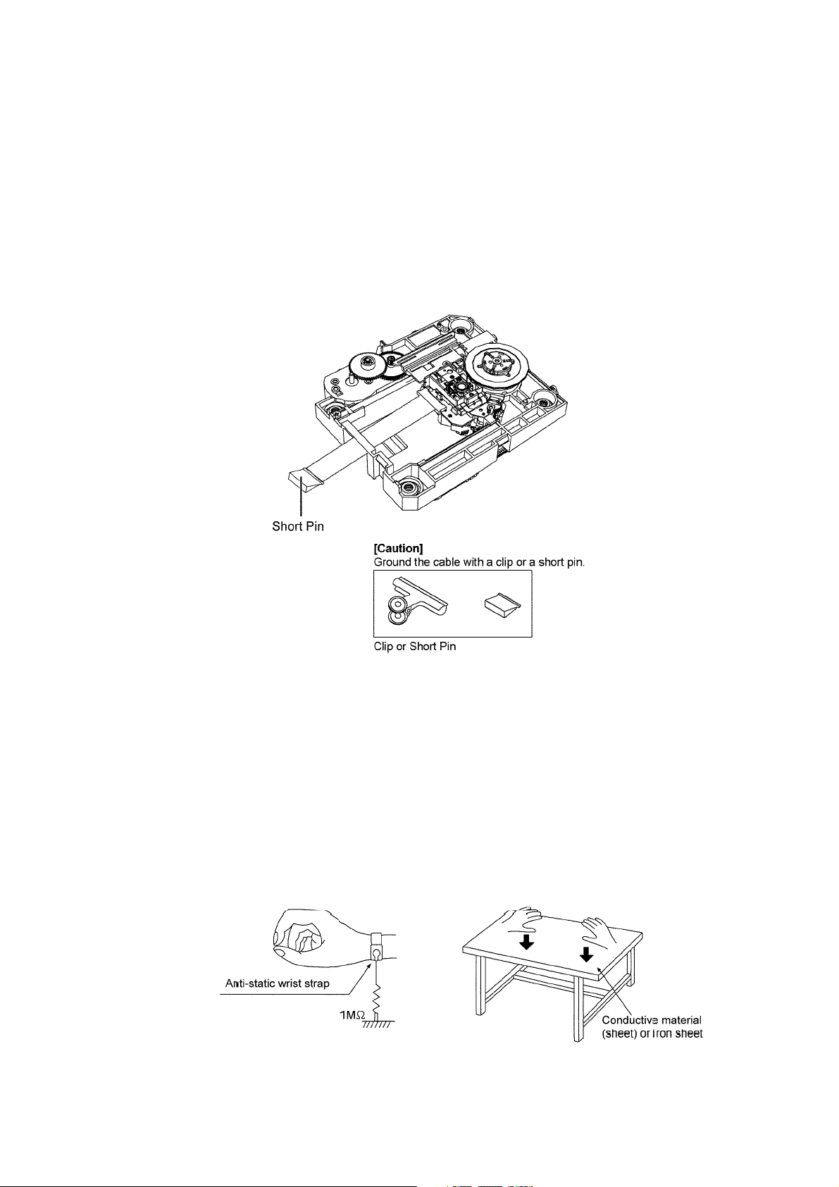
2.4. Handling Precaution for Traverse Assembly
The laser diode in the optical pickup unit may break down due to static electricity of clothes or human b ody. Special care must be
taken avoid caution to electrostatic breakdown when servicing and handling the laser diode in the Traverse Assembly.
2.4.1. Cautions to Be Taken in Handling the Optical Pickup Unit
The laser diode in the optical pickup un it may be damaged due to electrostatic discharge generating from clothes or human body.
Special care must be taken avoid caution to electrostatic discharge damage when servicing the laser diode.
1. Do not give a considerable shock to the optical pickup unit as it has an extremely high-precise structure.
2. To prevent the laser diode from the electrostatic discharge damage, the flexible cable of the optical pickup unit removed
should be short-circuited with a short pin or a clip.
3. The flexible cable may be cut off if an excessive force is applied to it. Use caution when handling the flexible cable.
4. The antistatic FPC is connected to the new optical pickup unit. After replacing the optical pickup unit and connecting the flexible cable, cut off the antistatic FPC.
Figure 1
2.4.2. Grounding for electrostatic breakdown prevention
Some devices such as the CD player use the optical pickup (laser diode) and the optical pickup will be damaged by static electricity
in the working environment. Proceed servicing works under the working environment where grounding works is completed.
2.4.2.1. Worktable grounding
1. Put a conductive material (sheet) or iron sheet on the area where the optical pickup is placed, and ground the sheet.
2.4.2.2. Human body grounding
1. Use the anti-static wrist strap to discharge the static electricity form your body (Figure 2).
Figure 2
9

3 Service Navigation
3.1. Service Information
This service manual contains technical information which will allow service personnel’s to understand and service this model.
Please place orders using the parts list and not the drawing reference numbers.
If the circuit is changed or modified, this information will be follow ed by supplement service manual to be filed with origi nal service
manual.
• Micro-processor:
1) The following components are supplied as an assembled part.
- Micro-processor IC, (IC5100 1) (RFKWMNE5PCM) (SL-NE5)
- Micro-processor IC, (IC51002) (RFKWMNE5PSM) (SB-NE5)
10
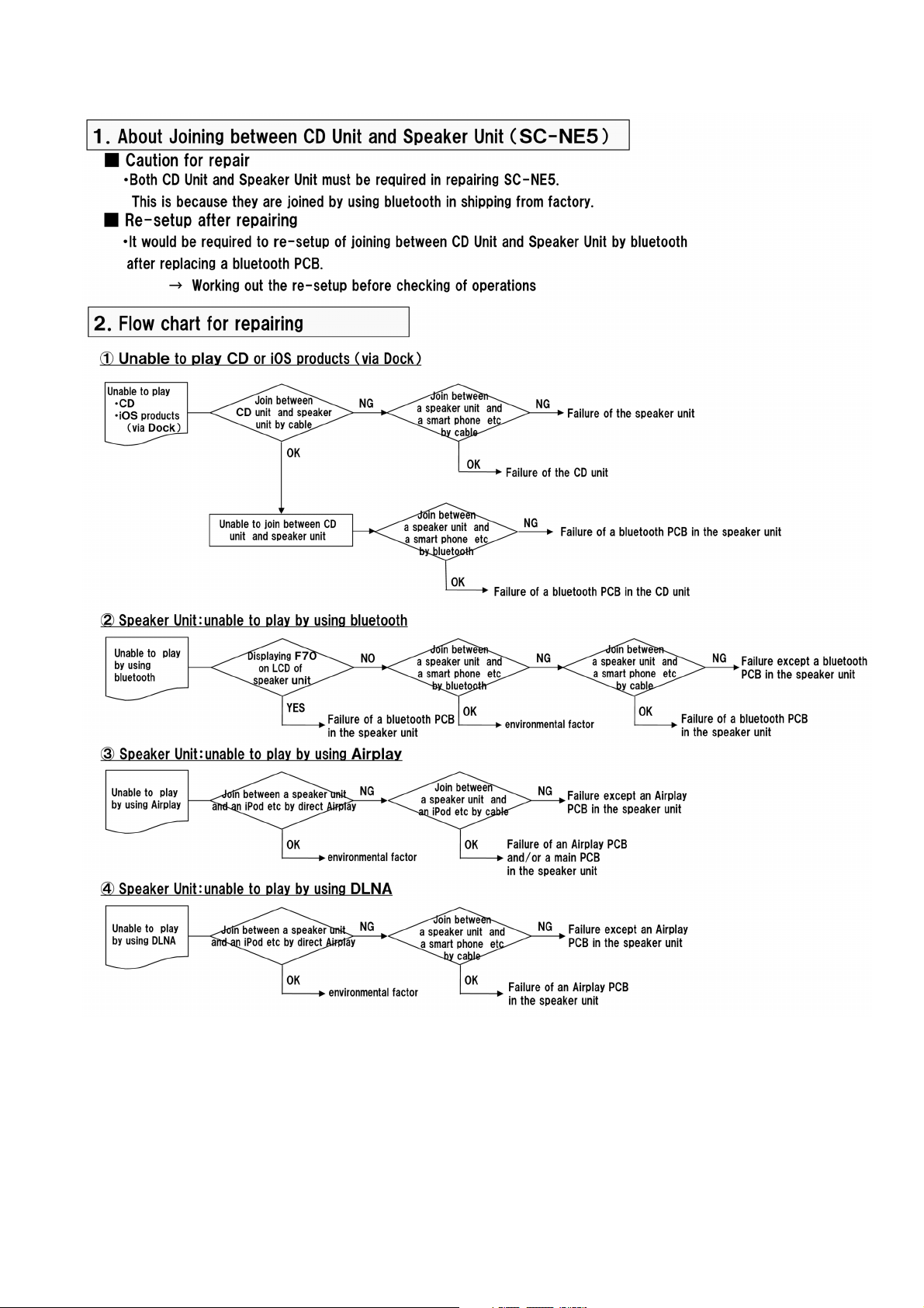
3.2. Troubleshooting Guide
11

4 Specifications
Q GENERAL
Power consumption
CD unit 23 W
Speaker unit 14 W
Power consumption in standby
*1
mode
CD unit Approx. 0.3 W
Speaker unit Approx. 0.3 W
Power consumption in standby
*1
(When “NET STNBY” is
mode
“ON”)
Speaker unit Approx. 4.0 W
Power supply AC 220 V to 240 V, 50 Hz
Dimensions (W × H × D)
CD unit 192 mm × 206 mm × 93 mm
Speaker unit 570 mm × 206 mm × 100 mm
Mass
CD unit Approx. 0.9 kg
Speaker unit Approx. 2.8 kg
Operating temperature range 0 °C to +40 °C
Operating humidity range 35% to 80 % RH (no condensa-
tion)
Q AMPLIFIER SECTION
RMS Output Power Stereo mode
Front Ch (both ch driven) 20 W per channel (6 Ω),1 kHz,
10% THD
Total RMS Stereo mode power 40 W
Wi-Fi
WLAN Standards IEEE802.11b/g
Frequency range 2.4 GHz band
Security WEP (64 bit/126 bit), WPA™,
WPA2™
WPS version Version 2.0 (WEP not support)
Q BLUETOOTH SECTION
Version
Output Class 2 (2.5 mW)
Communication distance
Communication method 2.4 GHz band FH-SS
Communication profile A2DP / AVRCP
Note:
*1: When th iPod/iPhone/iPad is not charging.
*2: Prospective communication distance
Measurement environment:
Temperature 25 °C / Height 1 m
Measure in “MODE 1”
• Specifications are subject to change without notice. Mass and
dimensions are approximate.
• Total harmonic distortion is measured by the digital spectrum analyzer.
Bluetooth
®
Ver.2.1 +EDR
About 10 m
*2
Q TUNER SECTION
Frequency Modulation (FM)
Preset Memory FM 30 stations
Frequency range 87.50 MHz to 108.00 MHz (50 kHz
step)
Antenna terminals 75 Ω (unbalanced)
Q TERMINALS SECTION
iPod Port
USB Standard USB 2.0 full speed
Media file format support MP3 (*.mp3)
USB device file system FAT12, FAT16, FAT32
iPod port power DC Out 5 V 2.1 A MAX
Lightning Connector DC Out 5 V 1.0 A MAX
AUX Terminal Stereo, Ø3.5 mm jack
Q DISC SECTION
Disc played (8 cm or 12 cm) CD, CD-R/RW (CD-DA, MP3)
Pick up
Wavelength 790 nm (CD)
Laser power CLASS 1
Audio output (Disc)
Number of channels 2 ch (FL, FR)
Q SPEAKER SECTION
Type 2 way, 2 speaker system (Bass
Speaker unit(s)
1. Woofer 8 cm × 1 per channel
2. Tweeter 2.5 cm × 1 per channel
Impedance 6 Ω
Output sound pressure 83.5 dB/W (1 m)
Frequency range 52 Hz to 25 kHz (—16 dB), 75 Hz
to 22 kHz (—10 dB)
reflex)
Q Wi-Fi/AirPlay SECTION
12
4.1. License
13
5 General/Introduction
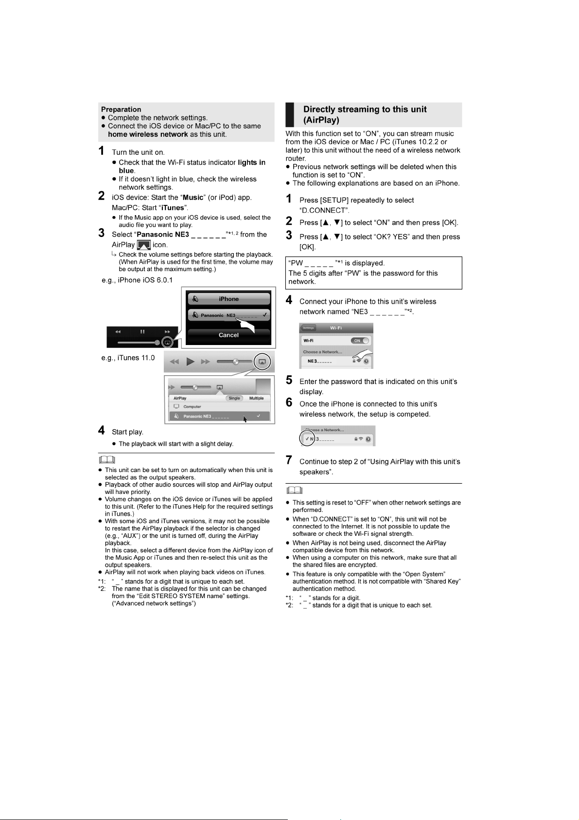
5.1. Using AirPlay with this system’s speakers
14
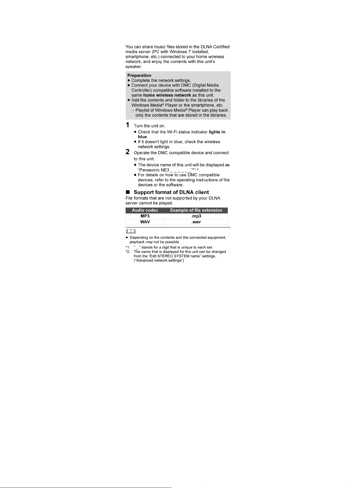
5.2. Playing back music files on the DLNA server
15
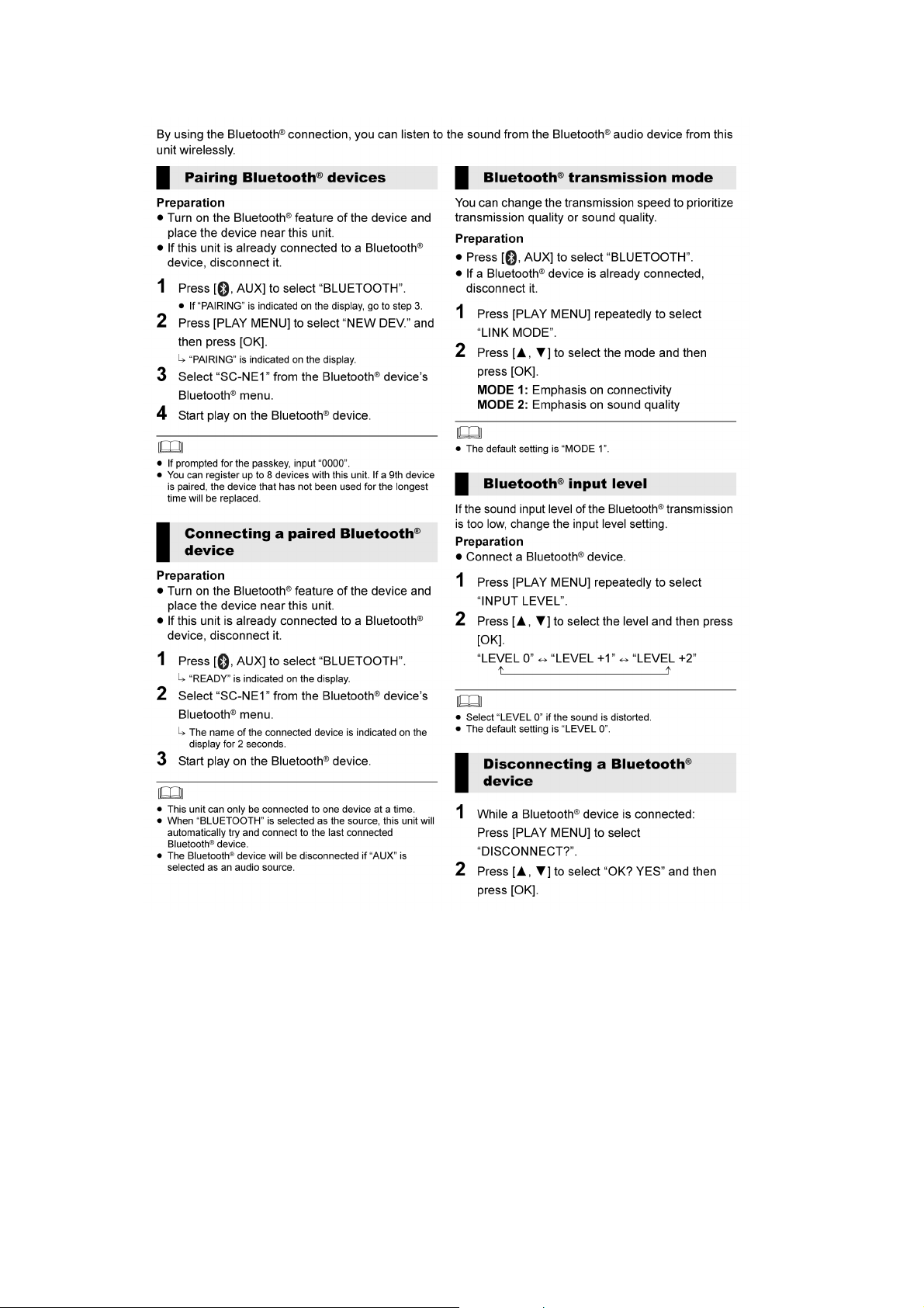
5.3. Bluetooth® Operations
16

5.4. Playable media
17
6 Location of Controls and Components
6.1. Main Unit Key Button Operations
18
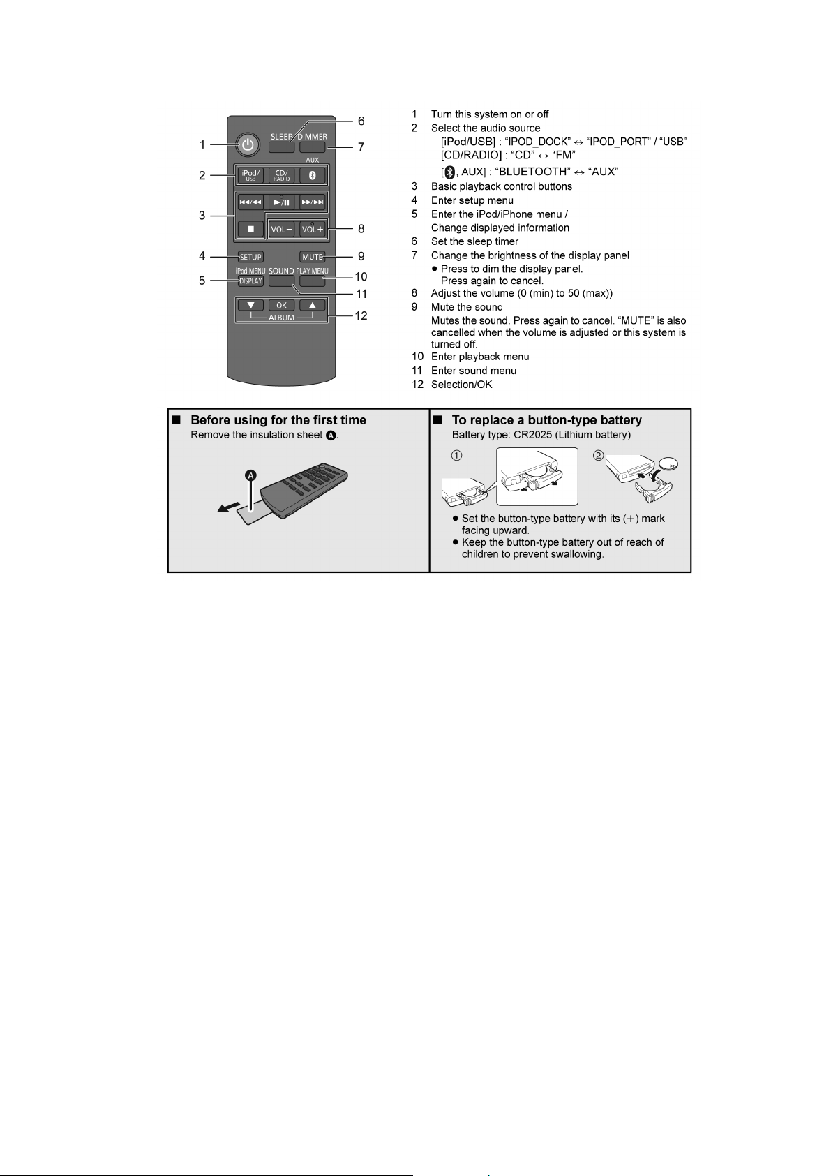
6.2. Remote Control Key Button Operations
19
7 Installation Instructions
7.1. Connections
20
7.2. Inserting media
21
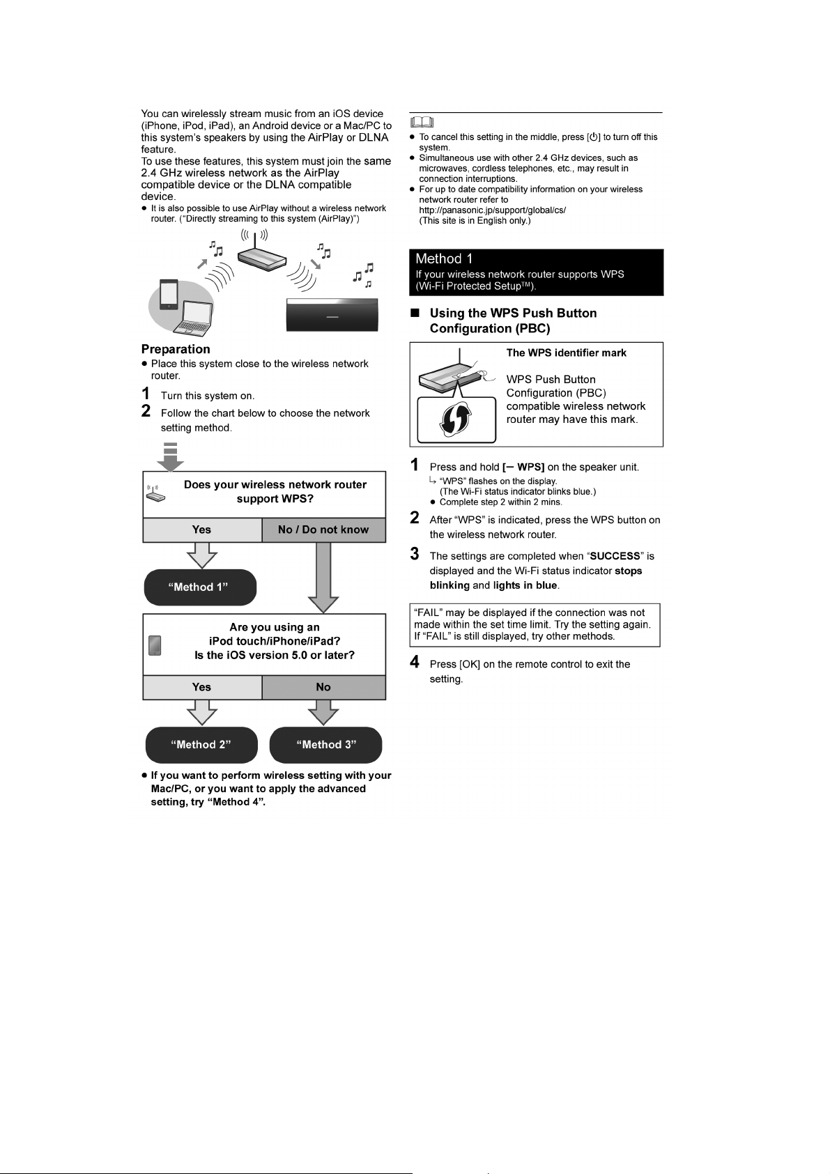
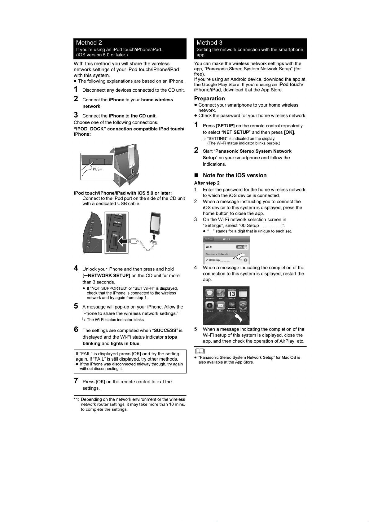
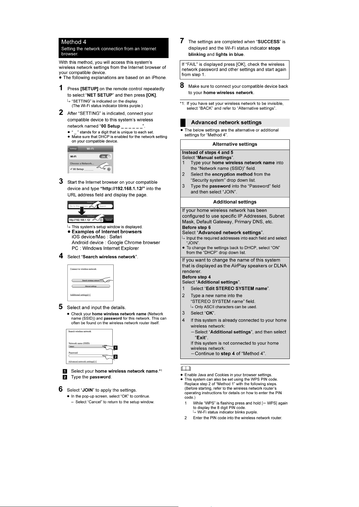
7.3. Network settings
22
232425
8 Service Mode
This unit is equipped with features of self diagnostic & doctor mode setting for checking the functions & reliability.
8.1. Self Diagnostic Mode
Here is the procedures to enter into Self Diagnostic Mode.
Step 1: Turn on the unit.
Step 2: Select SELECTOR mode.
Step 3: Press and hold [SELECTOR] button for 2 seconds follow by [VOL+] on the unit.
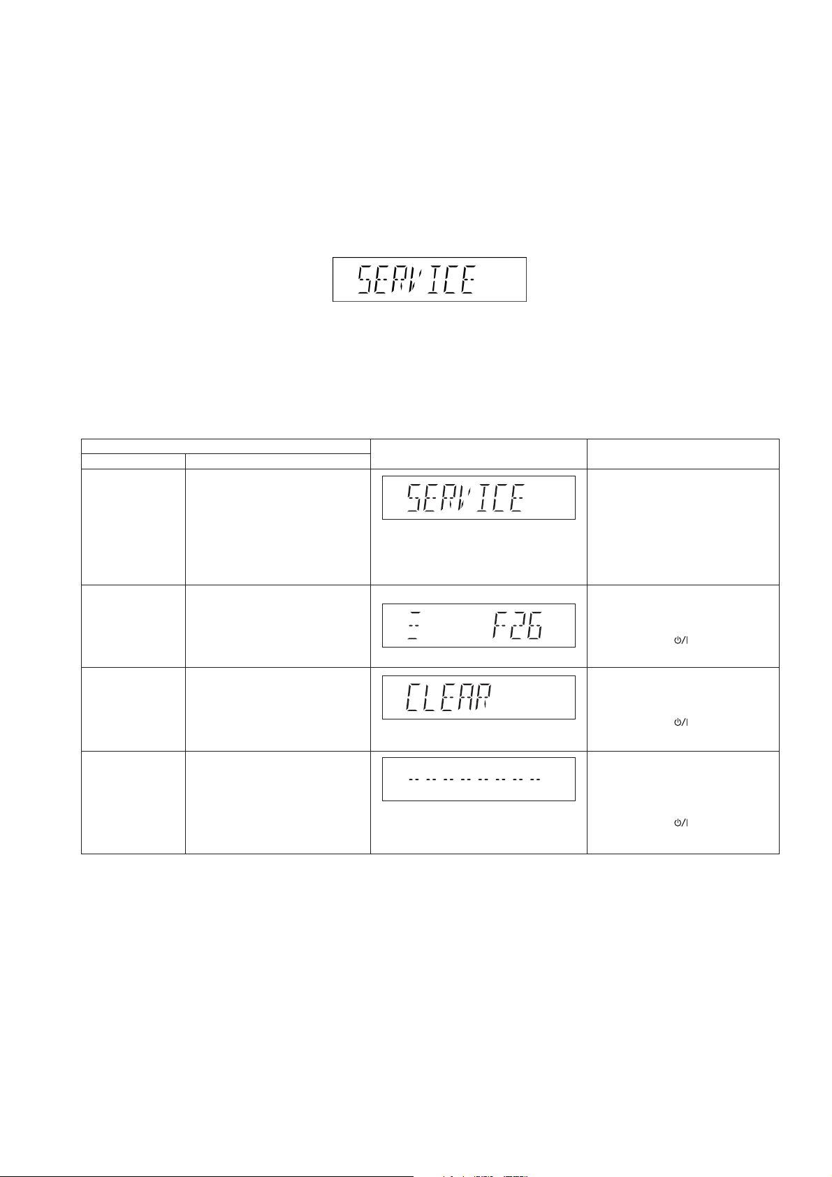
Step 4: The display show as follow.
To exit the Self Diagnostic Mode
Use either one of the following methods to cancel the Self Diagnostic Mode.
• Press the power button on the main unit or using the remote control.
• Unplug the AC cord.
8.1.1. Self Diagnostic Table
Item
Mode name Description
Self Diagnostic
Mode
Error code
information
Delete Error
code
Cold Start To activate cold start upon next
To enter into self diagnostic
checking.
any unusual/error code from
the memory.
To clear the stored in memory
(EEPROM IC).
power up.
(Backup date are initialized)
FL display Key operation
Step 1 : Select CD mode
(Ensure no disc is
inserted).
Step 2 : Press and hold
[SELECTOR] follow by
[VOL+] on main unit for
2 second.
Example:System will perform a check on
Step 1 : In self diagnostic mode,
Press [STOP] on main
unit.
To exit, press [ ] on main unit
or remote control.
Step 1 : In self diagnostic mode,
Press [0] on remote
control.
To exit, press [ ] on main unit
or remote control.
Step 1 : In service mode:
Press [SETUP] button on
the remote control of
HC55.
To exit, press [ ] on main unit
or remote control.
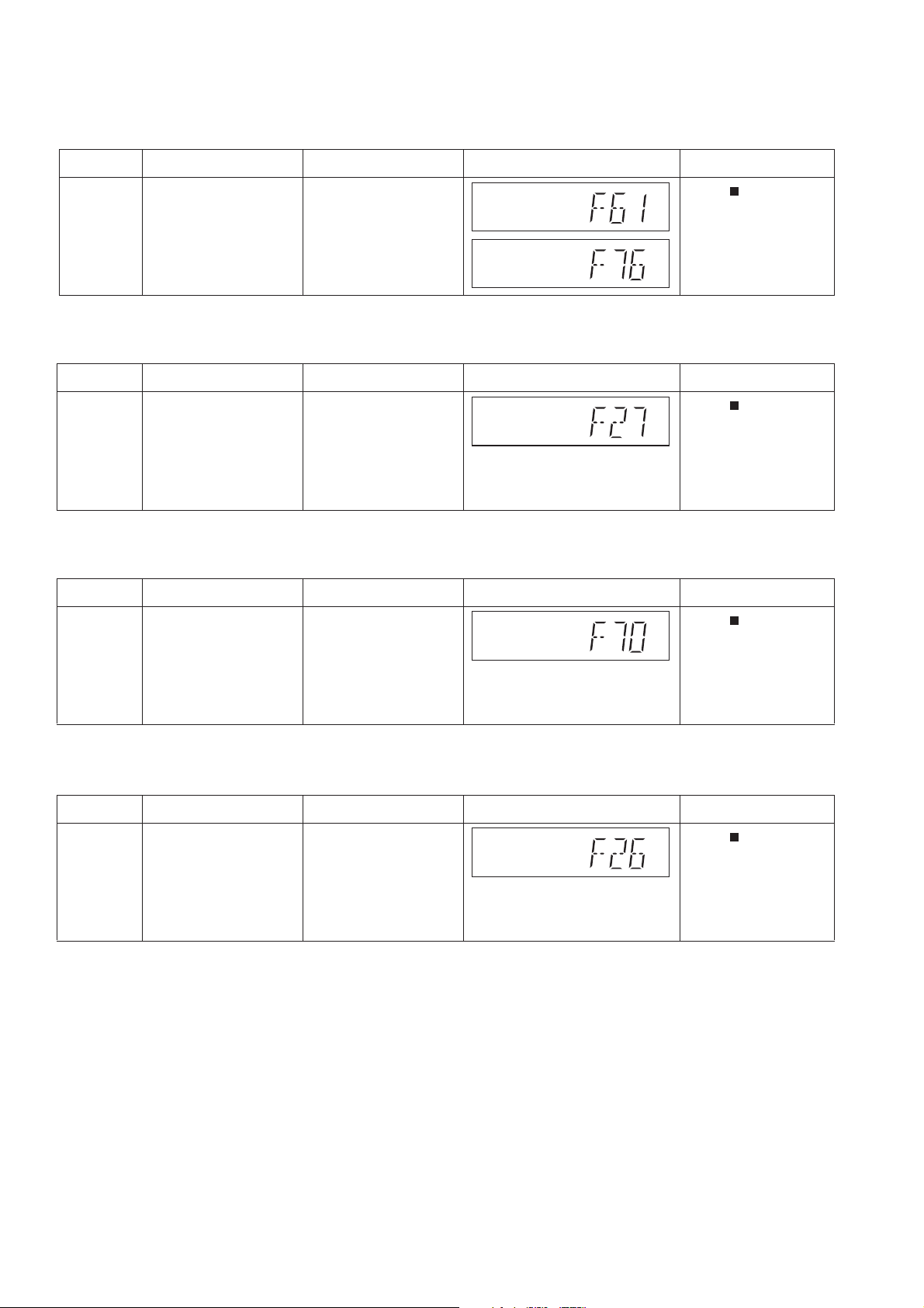
8.2. Self Diagnostic Function Error Code
8.2.1. Power Amp Error Code Table
Error Code Diagnostic Contents Description of error
F61/F76 Power Amp IC output
abnormal.
During power-on,
PDET1, PDET2 &
MAINV_DET /
TEMP_DET is “L” after
1 sec.
8.2.2. AirPlay Error Code Table
Error Code Diagnostic Contents Description of error
F27 Air Play Communication Communication between
Air Play module and
micro-p abnormal.
8.2.3. Bluetooth Error Code Table
Error Code Diagnostic Contents Description of error
F70 Bluetooth
Communication
Communication between
module and
micro-p abnormal.
Automatic FL Display Remarks
Press [ ] on main unit
for next error.
Automatic FL Display Remarks
Press [ ] on main unit
for next error.
Automatic FL Display Remarks
Press [ ] on main unit
for next error.
8.2.4. CD Error Code Table
Error Code Diagnostic Contents Description of error
F26 LSI Communication Communication between
CD servo LSI and
micro-p abnormal
(include iPod, USB).
Automatic FL Display Remarks
Press [ ] on main unit
for next error.
26
8.3. Doctor Mode Table (SB-NE5)
Note: To enter the Doctor Mode, please use HC55 remote control.
Here is the procedures to enter into Doctor Mode.
Step 1: Turn on the unit.
Step 2: Select CD mode.
Step 3: Pressing and hold [SELECTOR] on main unit then press [4] follow by [7] using the remote control.
Step 4: The display show as follow.
To exit the Doctor mode
Use either one of the following methods to cancel the Doctor mode.
• Press the power button of the unit or using the remote control.
• Unplug the AC cord.
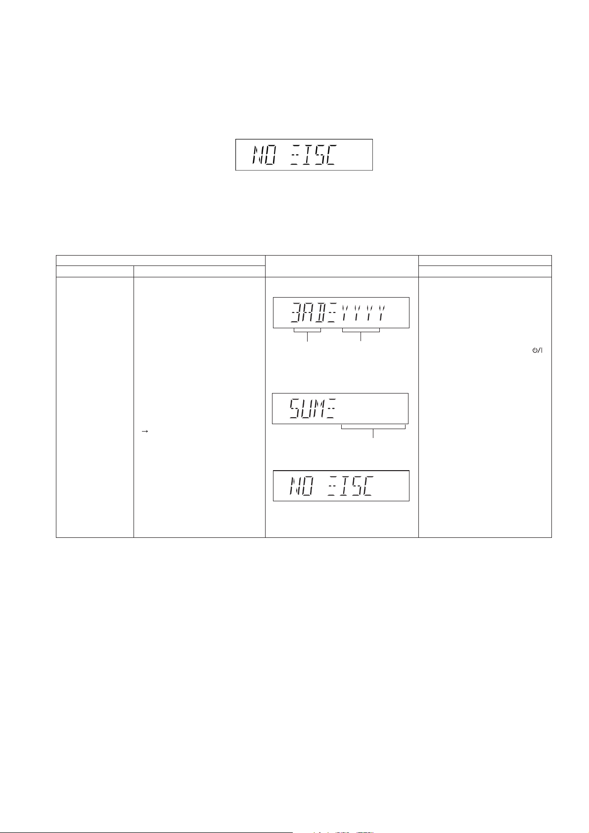
8.3.1. Doctor Mode Table 1
Item
Mode name
Doctor Mode To enter into Doctor Mode for
checking of various items and
displaying EEPROM and
firmware version.
Note: The micro-processor
version as shown is an
example. It will be revise when
there is an updates.
FL Display sequence Display
1 2
Description
FL display
(Display 1)
Version
Display
(DEC)
Checksum: (Condition 1)
The Checksum of EEPROM and
firmware version will be display for
2 sec.
Check sum
(HEX)
No Rom correction
(Display 2)
Key operation
Front Key
In any mode:
Press [SELECTOR] button on
main unit follow by [4] and the
[7] on the remote control of
HC55.
To exit Doctor Mode, press [ ]
button on main unit or on the
remote control of HC55.
27
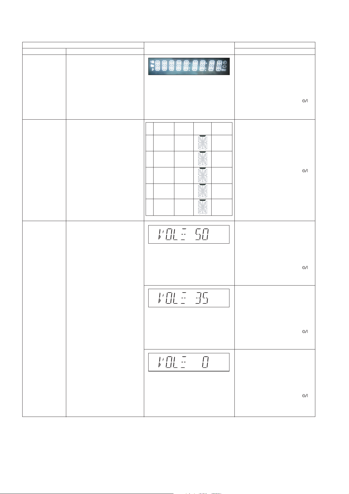
8.3.2. Doctor Mode Table 2
Mode name
FL Display Test
Tact SW
Inspection
Item
Description
To check the FL segments
display (All segments will light
up).
To conduct the acceptance of
all keys on the main set.
FL display
NE3/5
(SP unit)
1 POWER POWER
SELEC-
2
TOR
3 WPS D.BASS
4 VOL- VOL-
5 VOL+ VOL+
NE1
SELECTOR
FL
Display
RemarksNo
st
1 digit
of FL
nd
2 digit
of FL
rd
3 digit
of FL
th
4 digit
of FL
th
5 digit
of FL
Key operation
Front Key
In Doctor mode:
Press [1] button on the remote
control of HC55.
To cancel, press [0] button on
remote control. It returns Doctor
Mode.
To exit Doctor Mode, press [ ]
button on main unit or on the
remote control of HC55.
In Doctor mode:
In Bluetooth selector, press [2]
button on the remote control of
HC55.
To cancel, press [0] button on
remote control. It returns Doctor
Mode.
To exit Doctor Mode, press [ ]
button on main unit or on the
remote control of HC55.
Volume Setting
To check for preset volume
setting.
Note : In tuner mode this
function is not possible.
In Doctor mode:
Press [7] button on the remote
control of HC55.
To cancel, press [0] button on
remote control. It returns Doctor
Mode.
To exit Doctor Mode, press [ ]
button on main unit or on the
remote control of HC55.
In Doctor mode:
Press [8] button on the remote
control of HC55.
To cancel, press [0] button on
remote control. It returns Doctor
Mode.
To exit Doctor Mode, press [ ]
button on main unit or on the
remote control of HC55.
In Doctor mode:
Press [9] button on the remote
control of HC55.
To cancel, press [0] button on
remote control. It returns Doctor
Mode.
To exit Doctor Mode, press [ ]
button on main unit or on the
remote control of HC55.
28
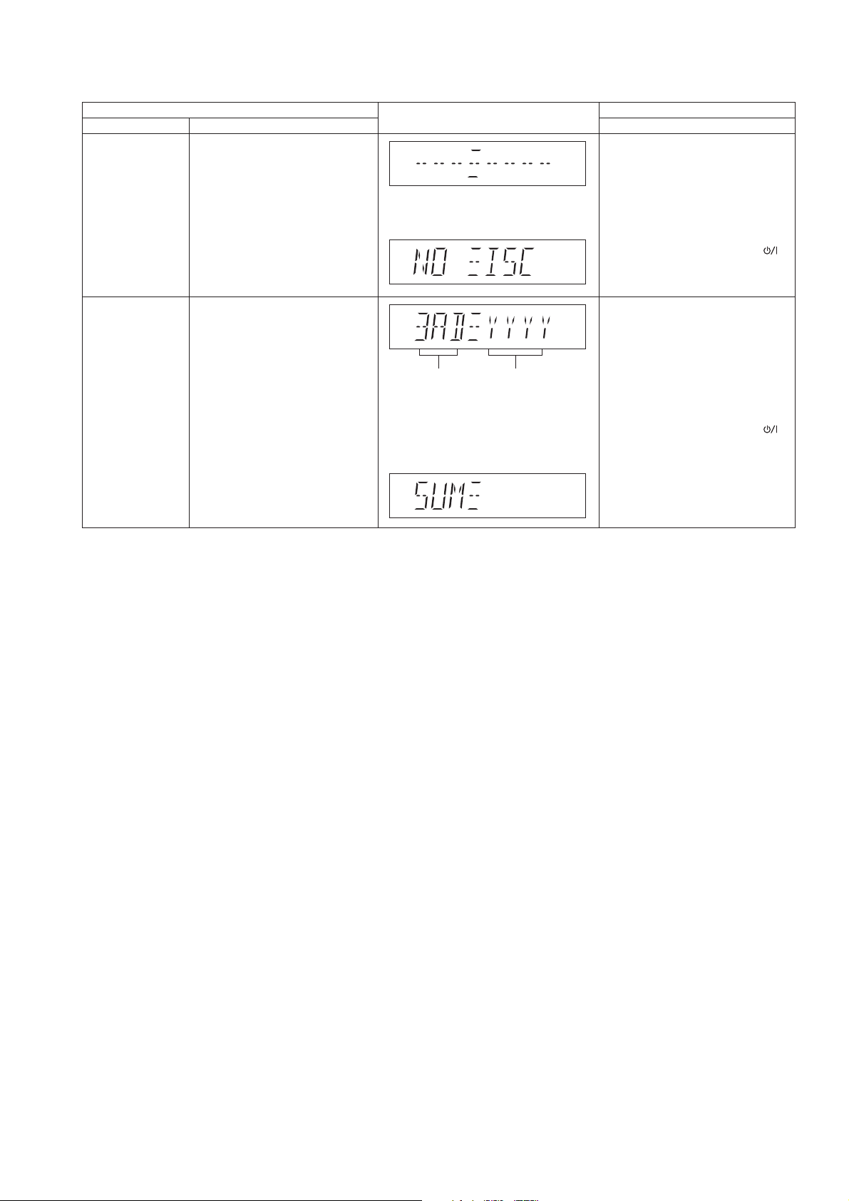
8.3.3. Doctor Mode Table 3
Item
Mode name
Cold Start To activate cold start upon next
power up.
(Backup date are initialized)
EEPROM
Checksum
To check sum of EEPROM for a
simplified ROM correction.
1. When EEPROM is not
detected, the only micro-p's
version shall be displayed
without an EEPROM's check
sum.
Description
FL display
The [NO DISC] display will appear
after 2s.
Version
Display
(DEC)
EEPROM not detected only
firmware is display.
Check sum
(HEX)
Key operation
Front Key
In Doctor mode:
Press [SLEEP] button on
the remote control of HC55.
To cancel, press [0] button on
remote control. It returns Doctor
Mode.
To exit Doctor Mode, press [ ]
button on main unit or on the
remote control of HC55.
In any mode:
Press [BT/AUX] button on main
unit follow by [4] and the [7] on
the remote control of HC55.
To cancel, press [0] button on
remote control. It returns Doctor
Mode.
To exit Doctor Mode, press [ ]
button on main unit or on the
remote control of HC55.
29
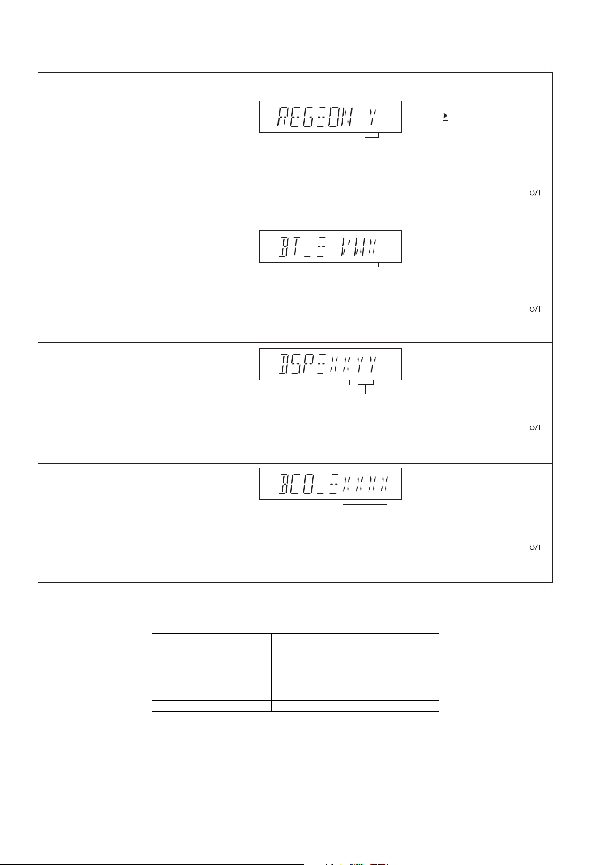
8.3.4. Doctor Mode Table 4
Item
Mode name
Description
Region Checking To check Region setting of unit.
Refer to 8.3.5 for the Region
Setting destination.
Bluetooth Version
Check
Yamaha DSP
Version Check
To check Bluetooth version
setting of unit.
To check DSP Firmware mode
and Version No.
FL display
Region Setting
destination
v = flash version (0~7),
w = flash sub version (0~F),
x = control version (0~F)
Firmware
Version No
(00~FF)
Firmware
Mode
(00~FF)
Key operation
Front Key
In Doctor mode:
Press [ 10] button follow by [1]
and then [6] button on
the remote control of HC55.
To cancel, press [0] button on
remote control. It returns Doctor
Mode.
To exit Doctor Mode, press [ ]
button on main unit or on the
remote control of HC55.
In Doctor mode:
Press [Play Timer] button on
the remote control of HC55.
To cancel, press [0] button on
remote control. It returns Doctor
Mode.
To exit Doctor Mode, press [ ]
button on main unit or on the
remote control of HC55.
In Doctor mode:
Press [6] button on the remote
control of HC55.
To cancel, press [0] button on
remote control. It returns Doctor
Mode.
To exit Doctor Mode, press [ ]
button on main unit or on the
remote control of HC55.
Air Play Version
Check
To check Air Play firmware
version.
8.3.5. Region Check Table
Region Model Series Country
1 NE5/3/1 P/PC North America
2 (D) NE5/3/1 Japan Japan
4 NE5/3/1 EG UK, Germany, France
5 NE5/3 EB UK
7 NE5/1 PU/GS S.E. Asia
9 NE5/3/1 GN Oceania
Firmware Version
No (0001 ~ 9999)
In Doctor mode:
Press [5] button on the remote
control of HC55.
To cancel, press [0] button on
remote control. It returns Doctor
Mode.
To exit Doctor Mode, press [ ]
button on main unit or on the
remote control of HC55.
30
 Loading...