

Page 1
Thank you for choosing
Panasonic
Omnivisian
Digital Video Cassette Recorder
MODEL PV-HD1000
DSQS
MTP
NTSC
Operating
Instructions
'able Box
Easy Taping.
Please read these instructions carefully before attempting to connect,
operate or adjust this product. Please save this manual.
Spanish Quick Use Guide is included. (Guía para rápida consulta en español está incluida.)
Quick Use Guide is on the back cover.
VQTS3525A
onirol
Page 2
Important Safeguards and Precautions
FOR YOUR SAFETY, READ AND RETAtN
ALL SAFETY AND OPERATING INSTRUC
TIONS. HEED ALL WARNINGS IN THE
MANUAL AND ON THE UNIT
INSTALLATION
1 POWER SOURCE CAUTION
Operate only from a power source indicated on the
unit or in this manual. If necessary, have your Electric
Utility Service Company or Video Products Dealer verify
the power source in your home.
2 POLARIZED OR GROUNDING PLUG
As a safety feature, this Video product comes with either
a polarized power cord plug (one blade is wider than the
other), or a three-wire grounding type plug.
POLARIZED PLUG CAUTION:
This plug wilt only fit into an outlet one way. If you cannot
fully insert the plug, try reversing it. If it still will not fit, have
an electrician install the proper wall outlet. Do not defeat the
safety feature by tampering with the plug.
GROUNDING PLUG CAUTION:
This plug will only fit into a three-hole grounding outlet. If
necessary, have an electrician install the proper outlet. Do
not defeat the safety feature by tampering with the plug.
3 POWER CORD
Make sure power cords are routed so that they are not
likely to have anything rest on them, roll over them, or be
in the way of walking traffic.
if an extension cord is used, make sure it also has either
a polarized or grounded plug and that the cords can be
securely connected.
Frayed cords, damaged plugs, and damaged or cracked
wire insulation are hazardous and should be replaced by
a qualified service technician.
Overloaded outlets and extension cords are fire hazards
and should be avoided-
4 DO NOT BLOCK VENTILATION HOLES
Ventilation openings in the cabinet release heat
generated during operation. If they are blocked, heat
build-up inside the unit can cause failures that may result
in a fire hazard or heat damage to cassettes.
For protection, follow these rules:
a. Never cover ventilation slots or the unit while in use,
or operate the unit when placed on a bed, sofa, rug,
or other soft surface.
b. Avoid built-in installation, such as a book case or
rack, unless proper ventilation is provided.
5 AVOID EXTREMELY HOT LOCATIONS OR SUDDEN
TEMPERATURE CHANGES
Do not place the unit over or near any kind of heater or
regulator, in direct sunlight, inside a closed vehicle, etc..
Do not move the unit suddenly between areas of
extreme temperature variation. If the unit is suddenly
moved from a cold place to a warm place, moisture
may condense in the unit and on the tape.
6 TO AVOID PERSONAL INJURY
• Do not place unsecured equipment on a sloping
surface.
• Do not place this unit on any support
that is not firm, level, and adequately
strong. The unit could fall causing
serious injury to a child or adult and
damage to the unit.
• An appliance and cart combination
should be moved with care.
Quick stops, excessive force, and
uneven surfaces may cause the
appliance and cart combination to overturn,
• Carefully follow all operating instructions and use
the manufacturer's recommended accessories
when operating this unit or connecting it to any
other equipment.
SAFE ANTENNA AND CABLE CONNECTION
If an outside antenna or cable system
is connected to the equipment,
be sure the antenna or cable system
is grounded so as to provide some
protection against built up static
charges and voltage surges.
Section 810 of the National
Electrical Code, ANSI/NFPA 70
(in Canada, part 1 of the Canadian
Electrical Code) provides information
with respect to proper grounding of the
mast and supporting structure, grounding
of the lead-in wire to an antenna discharge unit,
size of grounding conductors, location of antenna discharge unit, connection to
grounding electrodes and requirements for the grounding electrode.
KEEP ANTENNA CLEAR OF HIGH VOLTAGE POWER LINES OR
CIRCUITS
An outside antenna system should be located well away from power lines, electric
light or power circuits and where it will never come into contact with these power
sources if it should happen to fall. When installing an outside antenna, extreme
care should be taken to avoid touching power lines, circuits or other power
sources as this could be fatal. Because of the hazards involved, antenna
installation should be left to a professional.
If the unit has been in storage or moved to a new location,
refer first to the INSTALLATION section of these safeguards.
1
KEEP THIS VIDEO UNIT AWAY FROM WATER OR
MOISTURE OF ANY KIND.
2 IF EQUIPMENT IS EXPOSED TO RAIN, MOISTURE, OR STRONG
IMPACT, unplug the unit and have it inspected by a qualified service technician
before use.
3 DURING AN ELECTRICAL STORM
During a lightning storm, whether indoors or outdoors, or before leaving the unit
unused for extended periods of time, disconnect all equipment from the power
source as welt as the antenna and cable system.
4 WHEN THE UNIT IS PLUGGED IN
• Never expose the unit to rain or water. DO NOT OPERATE if liquid has been spilled
• Never drop or push any object through openings in the unit. Some interna! parts
• Avoid placing the unit directly above or below your TV set as this may cause
5 USING ACCESSORIES
Use only accessories recommended by the manufacturer to avoid risk of fire,
shock, or other hazards.
6 CLEANING THE UNIT
Unplug the unit. Then, use a clean, dry, chemically untreated cloth to gently remove
dust or debris. DO NOT USE cleaning fluids, aerosols, or forced air that could overspray, or seep into the unit and cause electrical shock.
Any substance such as wax, adhesive tape, etc. may mar the cabinet surface.
Exposure to greasy, humid, or dusty areas may adversely affect internal parts.
DO NOT SERVICE THIS PRODUCT YOURSELF
If, after carefully following the detailed operating instructions, this Video product
does not operate properly, do not attempt to open or remove covers, or make any
adjustments not described in the manual. Unplug the unit and contact a qualified
service technician,
IF REPLACEMENT PARTS ARE REQUIRED
Make sure the service technician uses only parts specified by the manufacturer, or
those having the same safety characteristics as the original parts. The use of
unauthorized substitutes may result in fire, electric shock, or other hazards.
HAVE THE SERVICE TECHNICIAN PERFORM A SAFETY CHECK
After any service or repairs to the unit, request the service technician to conduct a
thorough safety check as described in the manufacture’s service literature to
insure that the video unit is in safe operating condition.
OUTDOOR ANTENNA tNSTALLATION
USING THE VIDEO UNIT
into the unit. Immediately unplug the unit, and have it inspected by a service
technician. Fire and shock hazards can result from electrical shorts caused by liquid
contact inside.
carry hazardous voltages and contact can cause electric shock or fire hazard.
electrical interference. Keep all magnets away from electronic equipment,
SERVICE
Safety Precautions
Warning: To prevent fire or shock hazard, do not expose this equipment to rain or moisture.
1ШШ A
CTwc SHOCK] / f \
iTOFEN / # 4
CAUTO« ТОЙСОиСЕТ>«пекОГЕ1£СТПС»ЮСК,
PO MOT ACMOVE COVtn (Cfì BACIO
N0ueen-S£RV1CEABIE PARTS 1ГОЮЕ
RËfER SEnvtCMO TOOUAjJFIED BCRVICE PERSONNEL
This symbol warns the user that uninsulated voltage within the unit may
have sufficient magnitude to cause electric shock. Therefore, it is
dangerous to make any kind of contact with any inside part of this unit.
This symbol alerts the user that important literature concerning the
operation and maintenance of this unit has been included. Therefore, it
should be read carefully in order to avoid any problems.
АКГЕША
DtSCHAftSItwn
(ICC S£CnOM t1»a|
omxmocumm
Fovn ютсЕ GnxHiMa
ElECTM0£ 5YÏTDI
(НбСЛЮ ал. FART H}
Page 3

Table of Contents
Use
Enjoy
more!
Now!
Important Safeguards and Precautions
................................
2
Accessories..............................................................................4
Loading the Batteries..............................................................4
Introduction about D-VHS.......................................................5
Basic Connection (Antenna, D-VHS VCR, DTV Compatible TV)
Advanced Connections
One Time D-VHS VCR Setup
(Cable Box/ DSS Receiver Setup, Channel Memory, Auto Clock Set)
........................................................
........................................
...................
10-14
6, 7
8, 9
VHS Playback.........................................................................15
(Slow Motion, Still Picture, Frame'by Frame, Features for a Quality)
VHS Recording..................................................................16,17
• One Touch Timer Recording.............16 • Recording One Program
• Selecting the Input Mode
.................
17 While Watching Another
• Selecting Channels at the
D-VHS VCR
......................
...........
17
17
D-VHS (Digital) Playback.......................................................18
• Still (Freeze) Frame Picture
D-VHS (Digital) Recording
• One Touch Timer Recording.............19
.............
18
....................................................
19
Timer Recording................................................................20, 21
VCR Plus-F System Setup.....................................................22
VCR Plus+ System Programming
Multi-Brand Control Feature
MTS Broadcast / VHS Hi-Fi Stereo System
Tape Operation
• VHS Index Search
• Index Scan
• Shuttle Variable Speed Search.... 29 • Zero Search
........................................
Copying Your Tapes (Dubbing)
..............................................................
.............................
28 • Repeat Play
29 * One Minute Skip
.................................................
........................................
............................................
....................
..28 - 30
.....................................
..............................
.....................................
23
24, 25
26, 27
30
30
30
31
Special VCR Features............................................................32
• VCR Lock
• Weak Signal Display
..........................................
........................
32 • Warning Beeper
32
...............................
32
Other
Information!
Reset Channel, Clock............................................................33
D-VHS VCR & Cassette Information
• Reset all D-VHS VCR Memory Functions ... 34 * Head Cleaner...................35
• D.S.T. (Daylight Saving Time)
• To prevent accidental • Declaration of Conformity
erasure a recorded tape......................34 • Specifications
• Record / Playback Time
............
..................
34 . Cleaning the D-VHS VCR.................35
34
.....................................
.................
...................................
35
35
34, 35
On-Screen Displays (OSD)....................................................36
• Function & Channel Display
• Menu Screen
• VCR Status & Clock Display
...................................
............
36 • Blank Tape/No Video Signal
36 Indication
............
36 • Warning and Instruction
....................................................
Displays
................
36
36
Before Requesting Service...................................................37
Service Center List
................................................................
38
Warranty..................................................................................39
Spanish Quick Use Guide/Guia para rápida consulta.40 - 45
Location of Controls...............................................................46, 47
• Remote Control...................................46 • Multi Function Display
• Front View of the D-VHS VCR
...........
46 • Rear View of the D-VHS VCR
......................
..........
47
47
Quick Use Guide......................................................Back Cover
Page 4
Before Using
Congratulations
on your purchase of one of the most sophisticated and
reliable products on the market today. Used properly, it will
bring you and your family years of enjoyment. Please fill in
the information at right. The serial number is on the tag
located on the back of your D-VHS VCR.
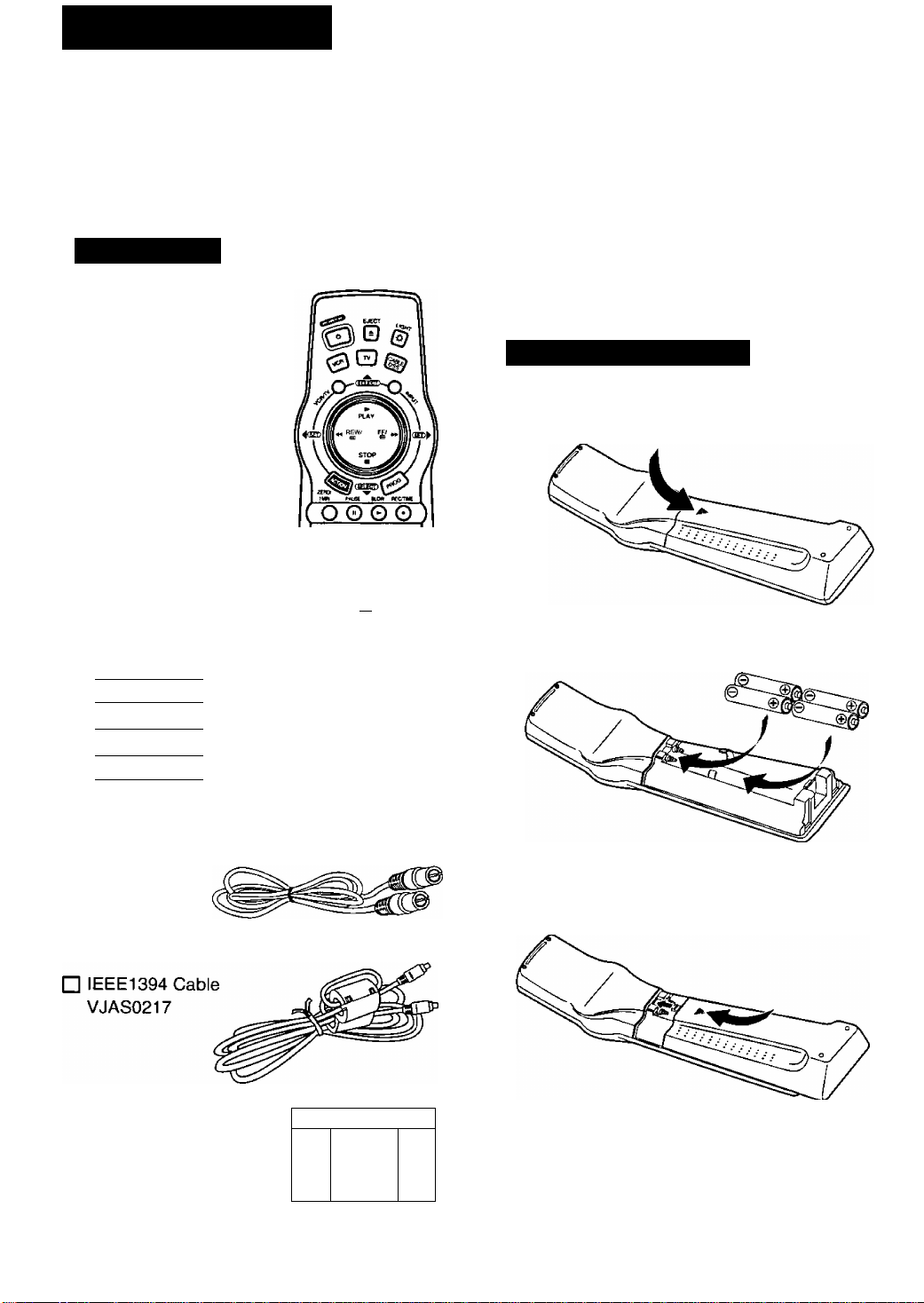
Accessories
□ Light Tower® Universal
Remote Control
VSQS1578
O © ©
0 0©
©00
__ accudì T
0
© @
VCL CH \
© G3 Qi
pts>>ov »cci
ai
□ 4 “AA” Batteries
« )
<p)
___
o m ©j
)
)
)
•Date of Purchase
•Dealer Purchased From
•Dealer Address_______
•Dealer Phone No.
•Model No.
•Serial No.
___________
_____
_____
Loading the Batteries
1 Press down on the H"- mark and slide the Battery
Compartment lid open.
2 Install four batteries as indicated inside the
Battery Compartment.
□ RF Coaxial Cable
VJAS0184
□ D-VHS Cassette tape
DF-300
To order accessories,
call toll free 1-800-332-5368.
I I
□
\
----
0
—
Slide the Battery Compartment lid back into place.
Battery replacement caution
• Do not mix old and new batteries.
• Do not mix alkaline with manganese batteries.
Page 5
Introduction about D-VHS
ABOUT D-VHS
The “D" in D-VHS represents Digital Data. As this name suggests, D-VHS is an extension of the world’s
most popular VHS home video format, which adds new digital recording (storage) capabilities that make it
an ideal match for digital broadcasts.
Like VHS, D-VHS is a tape-based format. Unlike VHS, D-VHS records digital signals as a digital bit streamj
(data) which is compatible with the MPEG II and ATSC standards utilized by your broadcast system.
Since digital data is stored “as is”, there is no loss of quality compared to the original broadcast.
And since you will want to continue enjoying all of the regular VHS tapes you’ve recorded or accumulated,
the D-VHS also offers conventional analog (VHS) recording and playback in addition to digital.
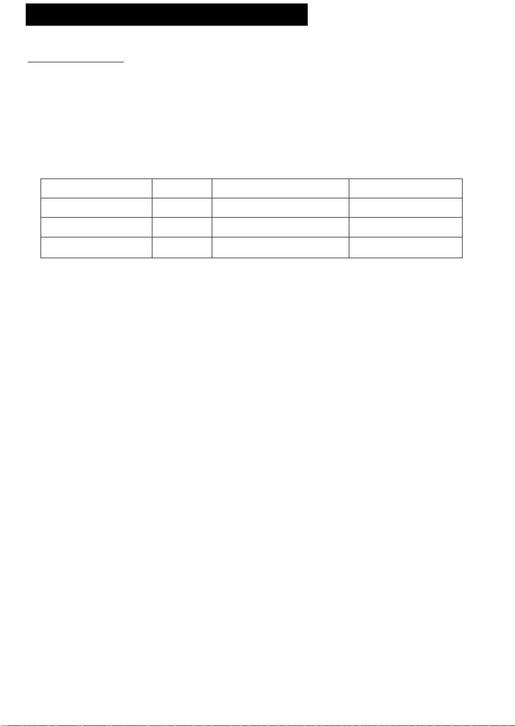
The relationship between type of broadcast, cassette D-VHS Switch, and resulting recording is as follows:
Broadcast Cassette D-VHS Switch Recording
Digital Broadcast
Digital Broadcast
Local
Local
D-VHS
D-VHS
PRODUCT FEATURES
FEATURES VHS Mode
REG SPEED
Hi-Fi
MTS/SAP
VCR P\us+
MULTI-BRAND CONTROL
SQPB (Super VHS Quasi Playback)
ON-SCREEN DISPLAY
181 -CHANNEL TV/CATV TUNER
VCR LOCK/WARNING BEEPER
REC/PLAYBACK/REW/FF/STILL
SEARCH (CUE/REV)
SHUTTLE SEARCH
SLOW/FRAME ADVANCE
TAPE
OPERATION
INDEX SEARCH
ZERO SEARCH
1-MINUTE SKIP
REPEAT PLAY
ONE TOUCH RECORDING
TIMER RECORDING
VHS
VHS
HS or HS/STD
HS or HS/STD or ANALOG VHS (analog)
HS or HS/STD or ANALOG
HS or HS/STD or ANALOG
SP/LP/SLP HS/STD
YES
YES
YES
YES
YES
YES
YES
YES YES
YES YES
YES
YES
YES
YES YES
YES YES
YES YES
YES YES
YES YES
YES YES
D-VHS (bit stream)
VHS (analog)
VHS (analog)
D-VHS Mode
*1
*2
*3
*4
*5
*1: There is no on-screen display during digital playback.
*2: The picture will be frozen during this operation.
*3: Digitally recorded tapes will have no on-screen displays.
*4: One touch recording is not functional when recording from a Set Top Box.
*5: For DTV timer program, tune the Set Top Box to the desired program, them it ON.
Page 6
Page 7

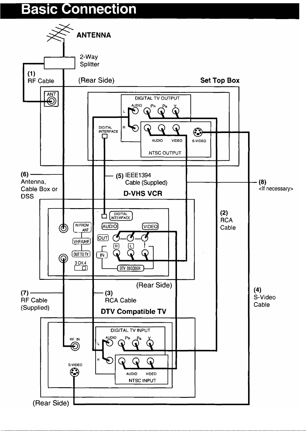
Explanations for Each Connection
(1) ANT (Set Top Box)
Connects the broadcast signal from your home antenna to receive Digital broadcasts.
To connect the broadcast signal to the D-VHS VCR, use a 2-Way Splitter {not supplied).
(2) Y, Pb, and Pr Jacks (Set Top Box)
Connects to Y, Pb, and Pr jacks on the Digital TV with RCA type cable to see digital
broadcasts and digital playback programs from the D-VHS VCR.
(3) AUDIO UR OUT Jacks (Set Top Box)
Connects to AUDIO L7R IN on the Digital TV to listen to Audio sound from the Set Top
Box. Y, Pb, Pr, and S-VIDEO jacks do not contain an audio signal. You cannot hear the audio
sound if these jacks are connected to the Digital TV.
(4) S-Video (Set Top Box) |
Connects to S-VIDEO on the Digital TV to see a high quality picture with NTSC.
(5) DIGITAL INTERFACE Jacks (Set Top Box)
Connects to DIGITAL INTERFACE jack on the D-VHS VCR with IEEE1394 Cable
(Supplied) to record and playback digital broadcasts.
• If IEEE1394 HUB is used, the D-VHS VCR may not operate correctly.
• The IEEE1394 cable may not be compatible for connection with other brand Set Top Boxes.
• Digital playback and digital recording with the D-VHS VCR is only possible if the signal is based
on MPEG 2 format.
Even with the D-VHS VCR connected to a DVC (digital video camera) with an IEEE1394 Digital
Interface cable, the D-VHS VCR cannot do a digital recording of the DVC playback, nor can the
DVC do a digital recording of the D-VHS VCR Playback.
(6) IN FROM ANT. Jack (D-VHS VCR)
Connects Antenna or Cable Box or DSS signal.
(7) OUT TO TV Jack (D-VHS VCR)
Connects to RF IN on the Digital TV with RF Cable (Supplied).
(8) AUDIOA^IDEO OUT (Set Top Box) <lf necessary>
Connects to AUDIOA/IDEO IN on the D-VHS VCR with RCA type cable to receive an
analog signal from the Set Top Box. Use this connection to record a digital broadcast
in VHS format with DTV selected as the input mode.
CAUTION: The D-VHS VCR should only be used with a Panasonic Set Top Box as other brands may not
function properly.
If you connect the DIGITAL OUTPUT on the Set Top Box to the DIGITAL INPUT on the DTV compatible TV
only, or the NTSC OUTPUT on the Set Top Box to the AUDIO/ VIDEO IN on the DTV compatible TV only,
some on screen displays such as MENU or PROGRAM will not be displayed.
• When “ ACT or “PRG” is dispiayed in the Multi Function Display, press ACTION or PROG to exit the MENU
or PROGRAM mode in order to operate the PLAY, STOP, REWIND, and FF buttons.
Page 8
Advanced Connections
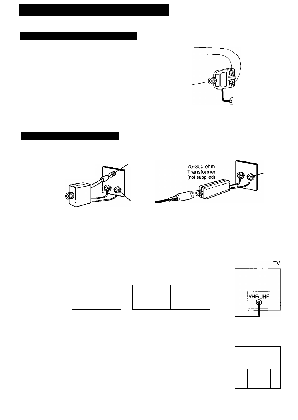
Between Antenna and D-VHS VCR
Case 1: Twin Lead Cable Only
To D-VHS VCR Terminal
m
(Flat) Twin Lead
300 Ohm Cable
300-75 ohm Transformer
(not supplied)
Between D-VHS VCR and TV
Case 1: Screw & Plug Type Terminal
UHFA/HF Band ^
Separator
(not supplied)
VHF
Case 2: Twin Lead & Coaxial Cables
(Round) 75 Ohm
coaxial Cable
Case 2: Screw Type Terminal
To D-VHS VCR Terminal
D
UHFA/HF
Band Mixer
(not supplied)
TV
VHF
or
UHF
RF Coaxial Cable
UHF
CATV Connection All connections on these pages are made with 75 Ohm coaxial cables.
■ With a Cable Box (Cable Box D-VHS VCR)
, ANT ^
t or '
\ CATV /
With a Cable Box (D-VHS VCR ^ Cable Box)
/ ant \
I or I
CATV '
CABLE BOX
IN OUT
(|) ©
IN FROM ANT.
1)
OUT TO TV
©
■ ®IN FROM ANT
®OUT TO TV
D-VHS VCR
D-VHS VCR
CABLE BOX
IN OUT
LfJ
TV
VHF/UHF
8
Page 9
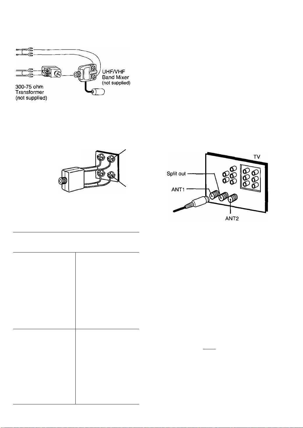
Case 3: Two Twin Lead Cables
To D-VHS VCR Terminal
Case 3: Double Screw Type Terminal
UHF/VHF Band
Separator
{not supplied)
TV
You Can You Cannot
• record or view any
(including
scrambled) channel. selected for any
• use D-VHS VCR
Remote Control to
select channels
using Multi-brand
control feature.
• view channel other
than the one
type of recording.
• do a Timer
recording of a
channel unless you
select it at the cable
box.
VHF
UHF
Case 4: Complex TV Terminal
TERMINALS ON BACK OF TV SET
Note to CABLE system installer;
This reminder is provided to call the CABLE system
installer's attention to Article 820:40 of the NEC in USA
(and to the Canadian Electrical Code in Canada) that
provides guidelines for proper grounding and, in
particular, specifies that the cable ground shall be
connected to the grounding system of the building, as
close to the point of cable entry as practical.
• view any (including • record scrambled
scrambled) channel.
channels.
•use D-VHS VCR
Remote Control to
select channels
without using Multibrand control
feature.
I Cassettes marked QlVHSI and [^H5l can be used
with this video cassette recorder. However, D-VHS
recordings are possible only with cassettes marked
DiVHSl.
HQ VHS is compatible with existing VHS
equipment.
Page 10

One Time D-VHS VCR Setup
The setup on pages 12 through 14 is vital for proper D-VHS VCR operation.
Please read the instructions carefully and in the order presented.
NOTE: These first two pages contain reference material needed for setup on pages 12-14.
Please look over the information before you begin setup procedure.
Setup Overview
You will be performing the following tasks:
• Telling the D-VHS VCR what kind of equipment you are using to receive channels and how it is connected.
• Entering pertinent cable box or DSS receiver information if used.
• Entering a local PBS channel so that the D-VHS VCR can receive auto clock set data. (Not available in all
areas.)
• Placing channels in memory and setting the clock.
Please Note Which Connection Type You are Using.
Make sure all equipment is hooked up as described on pages 6-11.
The‘diagrams below illustrate some of the basic connection types.
Confirm which type you used for later reference.
Connection Type A
C
Connection Type B
ONE TIME SETUP IMPORTANT NOTES:
• For detailed DSS receiver connection instruction, please see your DSS operating manual.
• The DSS receiver must be turned off to view programs from the cable box or antenna.
• If you use a DSS receiver, it must be turned off for auto clock set.
• If your cable box is not remote controllable, it must be tuned to your PBS channel.
• If you use AudioA/ideo Jack connection between the D-VHS VCR and cable box or DSS receiver, you must
also connect the RF coaxial cable in order to use the auto clock set and channel auto set features.
10
Page 11
Cable Box/ DSS Receiver Code Number List
If your cable box or DSS receiver is remote controllable, refer to this list during setup on page 12.
However, it will not operate all Cable Boxes or DSS Boxes made by these manufacturers.
If you get no results, your particular product brand cannot be controlled by this remote control.
Cable Box
Brand_______
Archer
.............................
Cableview
Citizen
Curtis
Diamond
Drake
Eagle
Eastern.....................................................28
GC Brand
Gemini
General Electric
General Instruments
....
Hamlin
Hitachi.................................................31,79
Jerrold
....
Macom
Magnavox
Matsushita
Movietime
NSC
Oak..........................................10,11,46, 99
Panasonic...................................16, 17, 101
Philips
Pioneer
Pulsar
Radio Shack
RCA
Realistic
Regal
Regency...................................................28
Rembran ................... 29, 32, 39, 42, 44, 88
Salora
Samsung
Scientific Atlanta
Sheritech..................................................27
SL Marx
......
04, 30, 42, 44, 52, 63. 85, 88
...........
.........................
............................................
.............
01, 02, 03, 04, 34, 55, 83, 85, 91, 93, 95
01,02, 03, 04, 34, 55, 83, 85, 91, 93, 95
..............................................
............................................
...................................................
04, 30, 42. 44, 52, 63, 85, 88
..........................
13, 20, 22, 26, 40, 58, 62, 98
......
04, 30, 42, 44, 52, 63, 85, 88
................................................
.............
................................................
..............................
............
.................................................
.......................................
14, 15, 28, 41, 97, 100, 102
.................................................
..................................
......
29, 32, 38, 39, 40, 42, 44, 88
.........................................
04, 30, 42, 44, 52, 63, 85, 88
...........................................
............................-..........
.........................
........
...........................
Code Numbers
01,29, 44, 88, 91
08, 09, 56, 61,87, 90
01,29, 44, 88, 91
37, 67, 71
04, 85
31,79
16, 17, 101
32, 38, 40
13, 20, 23, 24, 96
05, 06, 78
16, 17, 101
44, 51,88
14, 41
68, 72
32, 40, 42, 78, 94
08, 09, 56, 61,87, 90
32, 40, 42, 78, 94
57
25, 26
44
Brand
Spucer.........................................16, 17, 101
Stargate
04, 30, 32,40, 42, 44, 52, 63, 78, 85, 88, 94
Sylvania....................................................19
Teknika
....................................................
Telecaption................................................77, 92
Teleview
Texscan
Tocom
Toshiba.....................................................36
Uniden Satellite................................... 65, 69
Unika................................ 01,29, 44, 88, 91
Universal
Viewstar
Videoway
Vid Tech
Vidter
Zenith ............................................07, 23. 50
...........................
.....................................................
.................
....................
.........
.......................................
..................................................
.......................................................
01, 33, 34, 42, 48, 49, 91
13. 20, 22, 26, 40, 58, 62, 98
Code Numbers
74
32, 40, 42, 78, 94
16, 19
42, 43, 44, 52, 63, 88
07, 23, 50
64
64
DSS (Digital Satellite System Receiver)
Toshiba....................................................103
Hitachi/ Hughes.......................................104
Magnavox/Uniden 1
Magnavox/ Uniden 2
Sony........................................................107
RCA........................................................ 108
Panasonic
..............................................
..............................
...............................
105
106
109
Note: During setup you will be instructed to enter your brand code number. As some brands have multiple
codes, it may be necessary to try different codes to attain the proper results.
These codes are for Cable box or DSS Box setup for Auto Clock and VCR Ptus+ recording only.
For TV/Cable Box Multi-Brand Control operation, please see page 24.
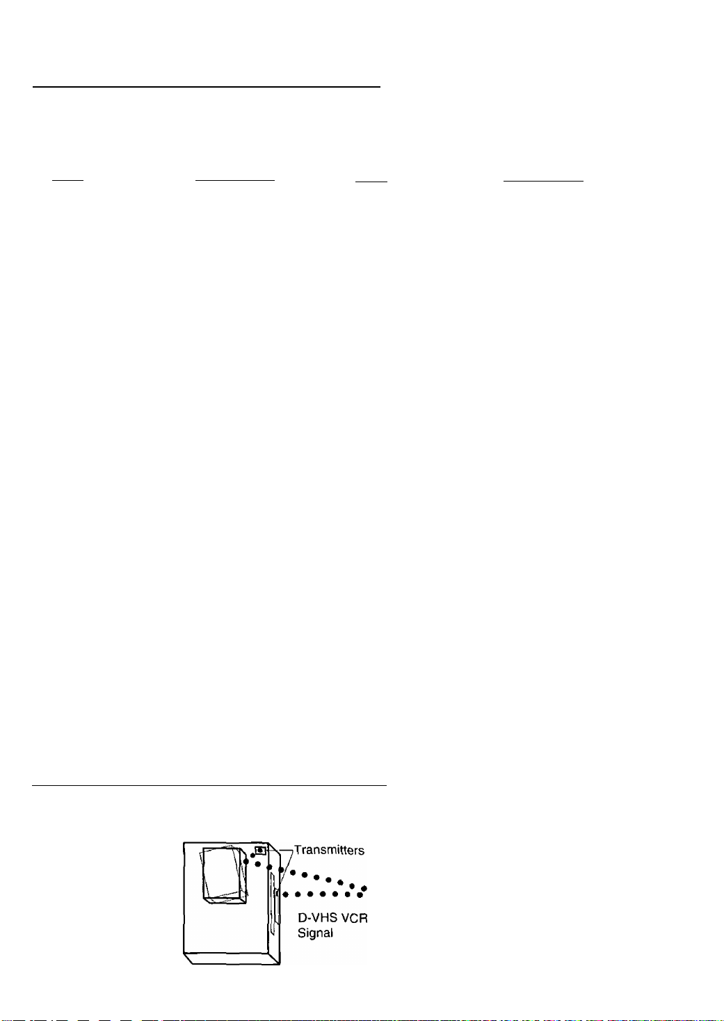
Positioning Your Cable Box or DSS Receiver
If your cable box or DSS receiver is remote controllable, place it on or near the D-VHS VCR as shown in the
example below. The D-VHS VCR transmits an infrared signal from two locations. Be sure not to cover the
transmitter windows.
i Wall
11
Page 12
One Time D-VHS VCR Setup (continued)
^Important: !f the remote control POWER, ACTION, PROG, CHA/V, INDEX or ADD/DLT button does not
When the D-VHS VCR is turned on for the
first time, it automatically enters the setup
mode.
Setup includes the following:
• Tell the D-VHS VCR how your equipment is
hooked up (pages 6~11) so the D-VHS VCR
can correctly place channels into memory.
• Get the D-VHS VCR ready for clock set.
10-11
work when pressed, press the VCR button on the remote and try the button again.
Back of
D-VHS VCR
To Set the Cable/DSS Receiver,
Channels and Auto Clock Set
1
Turn the TV and D-VHS VCR on.*
Tune your TV to the D-VHS VCR output channel
(the same one you set on the back of the D-VHS VCR; CH3 or
CH4).
• If you used audio/video jack connection, tune the TV to its video input.
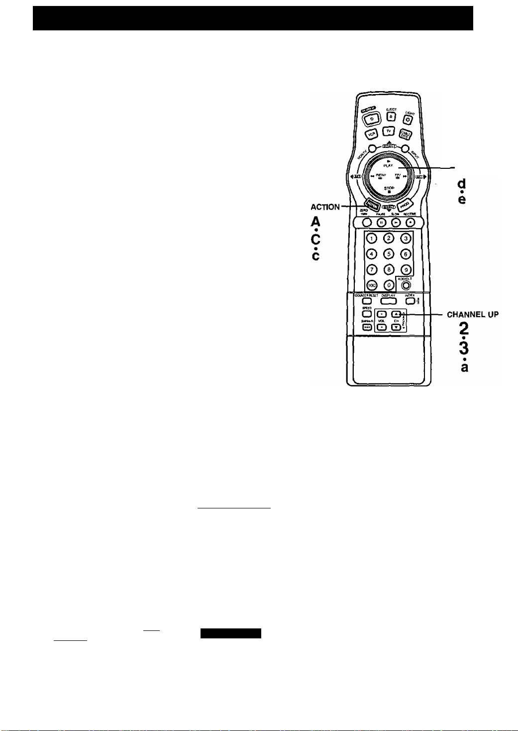
Press AT to select your connection
type, and then press ► to set.
• If you use a cable box or DSS receiver
and selected “YES”, go to step 4.
• If you selected “NO”, “CABLE BOX
CONTROL IS NOT AVAILABLE” is
displayed. Go to “Alternate Instructions”
on page 14.
Press AT to select your hookup,
and then press to set.
• If you selected “CABLE/DSS BOX ►VCR
►TV,” continue with step 5. If not, go to
“Alternate Instructions” on page 14.
• If you are using the CABLE/DSS BOX^
VCR^TV connection method, only the
cable box output channel will be placed in memory.
ARE YOU USING A CABLE
BOX OR DSS RECEIVER?
NO
SELECT;* ▼ KEY
SET :> KEY
END lACTtON KEY
SELECT HOOKUP
CABLE/D5S BOX^VCR^TV
VL.K*CABLE/DSS BuX*rv
SELECT:* ▼ KEY
SET : *. KEY
END :ACT I ON KEY
ACTION -
O © ©
© © ©
O ® ©
© © ©
O CD O l
O
Q ©I
VOL — ^
e
O Qi
Using ► keys
When a MENU or PROGRAM ^
screen is displayed, the Pl_AY, STOP,
REWIND, and FF buttons on the remote
control function as AT-^ ► only.
A.
O'
10
ft
11
Press AT to select your cable
box or DSS receiver output
channel number, and then
press ► to enter.
• If necessary, refer to your cable
box manual.
• If both a cable box and DSS receiver are used,
set the output channel of the DSS receiver,
• If you are using Audio/Video jack
connections to your cable box, select and
set “VIDEO OUT as the output channel.
SELECT HOOKUP
CABLE/DSS BOX*VCR*TV
CABLE/DSS BOX OUTPUT CH
SELECT
SET
END
Press AT to select your cable
box or DSS receiver code number,
and then press 1^ to enter.
(Refer to the list on page 11.)
• If your cable box or DSS receiver
doesn't have a remote control,
select “NO REMOTE.” Then, go to
Alternate Instructions on page 14.
• This determines whether the D-VHS VCR will
control your cable box or DSS receiver.
SELECT:* ▼ KEY
SET :► KEY
END :ACT I ON KEY
Continued on the next page.
* ▼ KEY
► KEY
ACTION KEY
ENTER CODE NUMBER
referring to manual
12
Page 13

If you use a cable box,
tune it to channel 02,
If you use a DSS receiver,
tune it to channel 270.
7 Press ► to continue.
• “NOW TRANSMITTING" appears.
If Cable Box
PLEASE TUNE YOUR CABLE
BOX TO CH02.
If DSS Receiver
PR
EN
PLEASE TUNE YOUR DSS
RECEIVER TO CH 270,
PROCEED:► KEY
END lACTION KEY
If the Auto Clock Set displayed time is incorrect...
If you use a cable box and receive
more than one PBS station, try auto
clock set again.
Follow the ‘To Set or Reset the Clock”
section on page 33 and when the
instructions call for you to enter a PBS
station, enter the one you have not
tried yet.
Press AT to select
8
“YES” or “NO,” and then
press ► to enter.
If you use a cable box and
selected “YES,” go to step 9.
If you use a DSS receiver
and selected “YES,” go to
“Alternate Instructions”
on page 14.
If you selected “NO,” the screen
in step 6 on page 12 will reappear. ____________________
If Cable Box
IS YOUR CABLE BOX
RECEIVING CH 09 ?
YES
SELEC
SET
El
If DSS Receiver
IS YOUR DSS RECEIVER
RECEIVING CH 2007
YES
(?gl
SELECT:* T KEY
SET : *■ KEY
END :ACTION KEY
Try entering a different code
assigned to your brand and/ or
repositioning the equipment (see page 11).
If the answer is still “NO,” cable box or DSS receiver
control is not available.
For channel and clock auto set, press ACTION to display
the “SET UP CHANNEL" screen. Then, press AT to select
“AUTO SET." Now, press ► and CH A to start the auto set.
Confirm that your cable box is on
and that your DSS receiver is off.
PLEASE ENTER YOUR LOCAL
9 Press AT to select your
PBS CHANNEL ON CABLE BOX
local PBS channel number
you receive on your cable
box, and then press ► to
display the “CLOCK AUTO
SELECT
SET
END
A T KEY
► KEY
ACTION KEY
SET” screen.
10 Press CH A to start Auto
Clock Set.
• If you live near a different time
zone, be sure to enter the PBS
channel in your time zone.
• “AUTO CLOCK SET
PROCEEDING” appears.
CLOCK AUTO SET
CONNECT ANTENNA CABLE
AND IF YOU USE A CABLE
BOX, TUNE IT TO YOUR
LOCAL PBS CH THEN. . .
PLEASE PUSH CH UP KEY
if “AUTO CLOCK SET IS INCOMPLETE” appears...
The screen below will appear on
screen if auto clock set data is not
available in your area.
AUTO CLOCK SET
IS INCOMPLETE
PUSH ACTION TO SET CLOCK
Press ACTION to display the “SET
CLOCK" (manual) screen, and
then do steps B and C on page 14.
Note:
If you use a cable box and receive
more than one PBS station, you may
exit the manual clock set screen and
try auto clock set again.
Follow the “To Set or Reset the Clock”
section on page 33 and when the
instructions call for you to enter a PBS
station, enter the one you have not
tried yet.
11 This display appears when
auto clock set is completed.
Confirm that the time is
correct and press CH A
to exit.
Auto clock set will be performed when the D-VHS VCR is turned off the first time each day. If you use a
NOTES
cable box and you want auto clock set to be performed, the cable box must be left on and tuned to the
PBS channel before the D-VHS VCR power is turned off.
It is necessary to set PBS CHANNEL to perform Auto clock set.
1/ 4/2000 TUE
SETTING : CH 02
AUTO CLOCK SET
'ID : PUSH CH UP KEY
COMPLETED
n-.m
OST:ON
13
Page 14
One Time D-VHS VCR Setup (continued)
•Important: If the remote control POWER, ACTION, PROG, CHA/V, INDEX or ADD/DLT button does not
work when pressed, press the VCR button on the remote and try the button again.
Alternate Instructions
Complete the following steps if, any of the following applies:
• You selected “NO” in step 3 on page 12.
• You selected “VCR^CABLE/ DSS BOX^TV” in step 4
on page 12.
• You selected “NO REMOTE” in step 6 on page 12
(your cable box or DSS receiver is not remote
controllable).
• You use a DSS receiver and selected “YES” in step 8
on page 13.
1 Turn on the cable box and
set it to the local PBS channel.
• If you live near a different time
zone, make sure to set the
channel in your time zone.
• If you use a DSS receiver,
it must be turned off.
Press CH A* to start Channel Auto Set and
Auto Clock Set.
• The follovYing messages appear.
“CH AUTO SET PROCEEDING”
“AUTO CLOCK SET PROCEEDING”
CHANNEL/CLOCK AUTO SET
CONNECT ANTENNA CABLE
AND IF YOU USE A CABLE
BOX, TUNE I T TO YOUR
LOCAL PBS CH THEN. . .
PLEASE PUSH CH UP KEY
SELECT/SET
►) keys
B
This screen appears to confirm that
auto clock set is completed.
1/ 4/2000 TUE12:
3 Confirm that the time is
correct and press CH A
to exit.
If this screen appears, auto
clock set is not available in
your area. Please set the clock
manually as described below.
A Press ACTION to display the
SET CLOCK screen.
B Press AT and ◄ ► to
select and set the month,
date, year, time, and
DST. (Daylight Saving Time).
To Make Corrections,
repeatedly press ► to move the cursor
to the incorrect entry and make the correction.
C Press ACTION twice to start
the clock and exit this mode.
MD : PUSH CH UP KEY
PUSH ACTION TO SET CLOCK
-\4y— SET CLOCK
/(X DST;ON
SELECT;* » KEY
SET ;► KEY
END : ACT! ON KEY
SET ► KEY
START : ACT I ON KEY
SETTING : CH 02
AUTO CLOCK SET
AUTO CLOCK SET
IS INCOMPLETE
DST:ON
COMPLETED
-----------
11 412000 TUE 12:
If the displayed time and DST. are not correct...
If you happen to live close to two time zones,
the D-VHS VCR may have recognized the
PBS channel (setting channel) in the wrong
time zone. Please do the following to correct
the situation.
a Make a note of the SETT1NG:CH number
shown on screen and press CH A to exit.
b Delete the setting channel from the D-VHS
VCR channel memory. (See the ‘To Add or
Delete a Channel’’ section on page 33.)
c Press ACTION to display the menu.
d Press AT to select “SET CLOCK," and then
press ► to display the “SET CLOCK” screen,
e Press AT and ► to select and set “AUTO
CLOCK SET.”
f Follow the One Time D-VHS VCR Setup
instructions on pages 12 ~ 14,
• If you use a cable box and have multiple PBS
stations, tune the cable box to a different PBS
station and try auto clock set using the menu.
14
Page 15
VHS Playback
[^Tcheck list before you begin.
Q Alt connections are made.
(See pages 6-11.)
Q TV and D-VHS VCR are plugged in.
Q TV is turned on and set to the D-VHS
VCR channel (CH3or4).
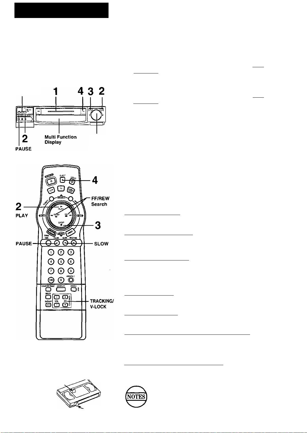
TRACKING/
V-LOCK
FF/REW
Search
1
Insert a cassette.
• D-VHS VCR power comes on automatically.
• “VCR” lights in the Multi Function Display.
2 Press PLAY on the remote or D-VHS VCR to start
playback.
• Playback begins automatically if cassette has no record tab.
3
Press STOP on the remote or D-VHS VCR to stop
playback.
• To rewind the tape, press REW.
4 Press EJECT on the remote or D-VHS VCR to eject
the cassette.
• You may eject a cassette with power on or off.
To Find a Particular Scene During Playback
Press REW or FF during playback to search for a scene.
• Search speed for SP mode tapes is 7 times and SLP mode tapes is
21 times the normal speed.
• Some noise bars will appear during search.
rCaution:
Please inspect your cassette tapes and
remove any loose or peeling labels to
prevent them from becoming jammed
in your unit. ^ ^
X
____
Special Effects During Playback
These features work best in SP or SLP mode. The sound will be muted.
Slow Motion Playback
Press SLOW to start slow motion playback during playback.
Press PLAY or SLOW to release.
Still (Freeze) Frame Picture
Press PAUSE to freeze and release the picture.
• To reduce picture noise, first press SLOW, Then, use CH
(TRACKING) A/T to clear up the picture. Now, press PAUSE.
Frame by Frame Advance
In Still mode, hold down SLOW to advance the stilt picture one frame at
a time. Press PAUSE to release.
Features for a Quality Picture
Digital Auto Picture
This feature automatically controls the video output signal for less noise
depending on the tape condition.
Digital Auto Tracking
This feature continuously analyzes the signal and adjusts for optimum
picture quality.
Manual Tracking Control (to reduce picture noise)
Use during Playback and Slow Motion mode to reduce picture noise.
Press CH (TRACKING) A/T during playback until the picture clears
up. To return to Auto Tracking mode, press POWER off and then on
again.
V-Lock Control (to reduce picture litter)
In Still mode, CH (TRACKING) ^T operate as a V-Lock control. Press
A/T until the picture is stabilized.
After the D-VHS VCR is in Still or Slow mode for 1
minute, it will switch to the Stop mode automatically to
protect the tape and the video head.
Above “Special Effects During Playback" and “Features for
y
a Quality Picture” are not available for D-VHS playback.
15
Page 16

VHS Recording
^Important: If thè remote control POWER, ACTION, PROG, CHA/T, INDEX or ADD/DLT button does not work
O All connections are made.
(See pages 6-11.)
O D-VHS VCR is piugged in.
r~l TV is turned on and set to the D-VHS
VCR channel (CH 3 or 4).
when pressed, press the VCR button on the remote and try the button again.
1
Check list before you begin.
Insert a cassette with record tab.
D-VHS VCR power comes on
automatically.
Press CH A/T* or NUMBERED keys to select a channel.
• Or, press CH A/T on the D-VHS VCR.
• Holding down CH A/T will increase
the channel search speed.
• To record from an outside source,
press CH A/V or INPUT to select
"LINE” (see page 17).
Press SPEED to change the
PAUSE
Multi Function Display
recording speed.
• SP = Standard Play
LP - Long Play
SLP = Super Long Play
(See page 34.)
t Press REC/TIME on the remote control or D-VHS
VCR to start recording.
• To edit out unwanted portions, press PAUSE to pause the
recording in progress.
To release, press PAUSE again.
(After the D-VHS VCR has been in Pause mode for 5 minutes, it
will stop automatically to protect the tape and video head.)
One Touch Timer Recording (OTR)
The D-VHS VCR starts recording and turns itself off at a preset time.
In step 4, press REC/TIME repeatedly to set the length of
the recording. Each push will change the stop time as
shown.
“TIMER” lights and the stop time is displayed in the Multi Function
Display.
The remaining recording time can be displayed by pressing
DISPLAY in OTR mode.
5
Press STOP to stop recording.
• Or, press STOP on the D-VHS VCR.
-Normal Rec—►0:30—»-LOO-
C
4:00-«—3:00-►“2:00 *«—1:30
16
Page 17

VCFVTV
VCR/TV
INPUT
Selecting the Input Mode
Press INPUT.
The display will change in the order below.
Channel
Number
c
Press CH A/T.
The display will change in the order below.
c
^LINE'
DTV: For rear audio/video connection of NTSC signal or
digital interface jack with IEEE1394 connection.
When DTV is selected, “d” is displayed in the Multi
Function Display.
LINE: For front audio/video connection.
When LINE is selected, “L” is displayed in the Multi
Function Display.
Record One Program While Watching Another
1 Press VCR/TV while recording is in progress to turn off
the VCR indicator in the Multi Function Display.
or
1 — 2—3-----------
DTV'^ 125 or 69
DTV-
U I V------------V
LINE
(CABLE) (TV)
-----
D
^
CHANNEL
Up/Down
2 Use the TV channel controls to select a program. The
VCR will continue to record your program while you
watch any channel you choose.
• To switch back and forth between the recording and viewing
channel, press VCR/TV.
Selecting Channeis at the D-VHS VCR
1 Turn your TV and D-VHS VCR on.
• VCR Indicator lights on the Multi Function Display.
If indicator doesn’t light, press VCR/TV to turn it on.
2 Use CH A/V on the remote control or D-VHS VCR to
select channels.
• To switch back to TV channel selection, press VCR/TV to
turn VCR indicator off, or simply turn the D-VHS VCR power
off.
17
Page 18

Digital) Playback
i^Check list before you begin.
□ Ail connections are made.
(See pages
D D-VHS VCR is plugged in.
□ Set Top Box and Digital TV are turned on.
1 Insert a pre-recorded D-VHS
cassette.
• D-VHS VCR power connes on automatically.
• “VCR" lights in the Multi Function Display.
N I
- VCR-
^ I \
2 Press PLAY on the remote or D-VHS VCR to
start playback.
• Playback begins automatically if cassette has no
record tab.
3
Press STOP on the remote or D-VHS VCR to
stop playback.
• To rewind the tape, press REW.
• To fast forward the tape, press FF.
4 Press EJECT on the remote or D-VHS VCR
to eject the cassette.
• You may eject a cassette with power on or off.
Additional D-VHS Playback Feature
Still (Freeze) Frame Picture
Press PAUSE to freeze and release the picture.
PAUSE
O © ©
0 0 0
© © ®
© © @
DtSPUtV tMSH
O CZI O I
BPEED
O
If "NOT PRESENT" is displayed on the screen,
even though connections are made correctly, turn
the Set Top Box power off and then on again.
Digital programs recorded on other brand digital
VCRs may not play back on this D-VHS VCR.
This D-VHS VCR can play back tapes with copy
protection.
However, the TU-DST50 Set Top Box is not
compatible with copyrighted programs.
To watch copyrighted programs, a compatible Set
Top Box is necessary.
When copy protected program is detected during
digital playback, “CP”(Copy Protection) is
displayed in the Multi Function Display.
When “CP” is displayed in the Multi Function
Display and the Set Top Box is not compatible
with the copyrighted program, the screen will turn
solid black.
When playing back tapes recorded with multiprograms, you can select the desired program for
playback using the Set Top Box remote control.
If the picture is not displayed during digital
playback, press STOP and PLAY again.
18
Page 19

D-VHS (Digital) Recording
NOTE: When using Panasonic Set Top BoxTu-0ST50 or TU-DST51, 0-VHS switch -
should be set to HS mode. Maximum recording Time will be 2.5 hours (DF-300 Tape)
iN^Check list before you begin.
□ All connections are made. (See pages 6~11.)
□ D-VHS VCR is plugged in.
□ Set Top Box is turned on.
1
i ! « «
PAUSE
PAUSE
d—^
o © ©
0 © ©
© © ©
^ «>c«XT
© © @
. OfSPlAV MC4
O CD O l
SPEEQ
O
1 Insert a D-VHS cassette with
record tab.
• D-VHS VCR power comes on automatically.
2 Select a recording channel with
the Set Top Box.
• If necessary, refer to your Set Top Box manual.
3 Press CH A/W or INPUT to select “DTV” (see
page 17).
4 Slide D-VHS Switch to HS or HS/STD.
• D-VHS indicator will light.
HS: Digital recording is d-VHS Switch
peiiormed.
Tape speed is SP
(Standard Play) mode and
recording period is 2.5
hours when DF-300
tape is used.
HS/STD: HS or STD (Standard) recording is selected
automatically.
ANALOGiAnalog recording is performed. To change the
recording speed, press SPEED (see page 34).
CJEZQ
5 Press REC/TIME on the remote or D-VHS VCR
to start recording.
• To edit out unwanted portions, press PAUSE to
pause recording.
O I ANALOG
HS^TO
Id
If “INPUT SIGNAL NOT
FOUND” is displayed on the
screen and/or “SnF" is displayed
in the Multi Function Display
during digital recording, make
sure the IEEE1394 cable is
properly connected and/or turn
the Set Top Box power ott and
then on again.
You can view only the channel
being recorded during D-VHS
recording.
-J
Caution:
Unauthorized exchanging and/or copying of
copyrighted recordings may be copyright
infringement.
One Touch Timer Recording (OTR) ^
The D-VHS VCR starts recording and turns itself off at a preset time.
In step 5, press REC/TIME repeatedly to set the length
i of the recording. Each push will change the stop time.
• “TIMER" lights and the stop time is displayed in the Multi Function
Display.
NOTE: If you start the recording with recording command feature of
\
______
the Set Top Box, the One Touch Timer Recording is not
available.
______________
__________________________
6 Press STOP on the remote or D-VHS VCR to
stop recording.
NOTE: Programs which have copy protect data cannot be recorded
and recording will be stopped. Then ‘THIS PROGRAM IS
RECORD PROHIBITION" is displayed on the screen.
When copy protected program is detcted during digital
recording, “CP"(Copy Protection) is displayed in the Multi
Function Display.
y*
19
Page 20

Timer Recording
^Important; If the remote control
work when pressed,
You can set up the D-VHS VCR to record a one
time, daily, or weekly program while you are
away or otherwise occupied. Up to 8 programs
can be stored in memory.
[^^Check list before you begin.
Q All connections are made.
(See pages 6-11.)
n TV and D-VHS VCR are plugged in and
turned on.
^ VCR/TV selector is set to “VCR.”
Clock is set to correct time.
Record tab in place. (See page 34.)
^ When Digital Timer Recording, use the
D-VHS cassette tapes.
POWER, ACTION, PROG, CHA/T, INDEX or ADD/DLT button does not
press the VCR button on the remote and try the button again.
1 Press PROG* to display the
“SET PROGRAM” screen.
Press AT to select ‘TIMER
PROGRAM,” and then press ►
to display the program screen.
* If a program is already in memory, press AW
and ► to select an unused program number.
3 Press AT and ► to select and
set one of the following:
• 1-31 =One time recording
• DAILY =Same time MON-FRI
• WEEKLY (SUN-SAT) =Same time once a week
Example ^^8—9
Today’s Date
-----
4 Press AT and to
select and set each of the
remaining items at right.
If you want to record digital TV,
channel selection should be "OTV.”
.......
3i— i — 2 6—^
7 SELECTA/V Selactlon order DAILY
L WEEKLY WEEKLY WEEKLY J
^ (SAT) (MON) (SUN)
Remaining Items to be set;
• START time • STOP time
• CH(annel) number, DTV or
LINE for outside source recording
• Speed (SP, LP, SLP)
--------
SET PROGRAM
VCR PIUS+ PROGRAM
SELECTS ▼ KEY
SET ;► KEY
END ;PROG KEY
START STOP CH
ESQ
SELECT:* » KEY
SET ;► KEY
ENO : PROG KEY
---------
important notes when using a DSS receiver
• When recording programs via a DSS
receiver, the DSS receiver must be left on.
• When recording programs via an antenna or
cable, the DSS receiver must be turned off.
To Make Corrections
Repeatedly press ► to move the cursor to the right, or ^ to
move to the left to the incorrect entry and make the correction,
D Press PROG to end the program.
• This screen appears for confirmation.
If you use a DSS receiver and enter a
channel number of 100-125, the screen
at right appears.
Press AT to select “DSS" or
“CABLE,” and then press ► to enter.
• The confirmation screen appears
above right after this selection.
To Enter More Programs
Press AW and ► to select and set a blank
program number, and then repeat steps 3 and 4.
6 Press PROG to exit this mode.
Press POWER off to set the timer.
• When recording programs via a cable
box, make sure the cable box is left
ON and tuned to the desired channel.
• For DTV Timer Recordina. make sure the set
too box fTU-DST50) IS left ON, and turned to
the desired channel. On the VCR, D-VHS
switch IS set to HS or HS/STD and oower is off.
-¡¡11112-
Multi Function Display
NOTES
20
Digital programs which have copy protect data cannot be recorded.
A cassette with no record tab is ejected and “TIMER” flashes when the power is turned off to set the timer.
If the start times of two programs overlap, the lower numbered program will have priority.
If the start time for a timer recording comes up during a normal recording or One Touch Recording (pages 16,17,
19), the timer recording will not be performed.
If there is a power interruption of more than one minute, the recording will not be performed or continue.
If a timer recording by the D-VHS VCR and by the Set Top Box overlap, only the earlier program will be performed.
Page 21

POWER
L|__
^
------------------
POWER
STOP
-----
1-
-----
Multi Function Display
STOP
Ö^0
SELECT/SET
keys
PROG
Cancel a Timer Recording:
{Recording is in progress)
Press POWER and then STOP within 10 seconds to
cancel the timer recording.
• The TIMER indicator goes out in the Multi Function Display.
Replace Program Contents:
(Recording is not in progress)
1 Press PROG to display the “SET
PROGRAM” screen.
2 Press AT to select “TIMER
PROGRAM,” and then press ► to
display all currently set programs.
3 Press AT and ► to select and
set a program number.
{See page 20.)
4 Press AT and ◄ ► to select
and set replacement timer
information.
5 Press PROG twice to exit this mode.
--------
SET PHOGHAM
VCR Ptu$+ PROGRAM
P DT START STOP CH SPD
2 8 10
OOP 12
OOP 9
OOP 10
OOA125 SP
OOP 10 SP
OOP L LP
3 10 8
SU 9
SELECT 1-6:A T KEY
ENTER :► KEY
END iPflOG KEY
DATEI, START STOP CH
8 SAT 10:OOP12:OOP 125
fODfti/' SUP
ЙЙМММDBBаМES0
SELECT:* ▼ KEY
SET ► KEY
END IPROG KEY
--------
O © ©
© © ©
© © ©
_
ADOiOLT
© ©
axMiutnuFT nsPLAv imxx
O
Q Qi
o
VOL Ol 4
a Qi
a
POWER
II ■44
A SELECT V SET
oi
Multi Function
Display
►
N
►
ADD/
DELETE
Review or Clear Program Contents:
(Recording is not in progress)
1 Press PROG to display the “SET
PROGRAM” screen.
2 Press AT to select “TIMER
PROGRAM,” and then press ► to
display all currently set programs.
3 Press AT to select a program
number.
4 Press ADD/DLT if you want
to clear the program.
5 Press PROG to exit this mode.
Timer Recording Using D-VHS VCR Buttons
(Make sure a cassette tape is not inserted in the D-VHS VCR.)
1 Hold down REC/TIME and press FF to enter the Program mode.
2 Press REW or PLAY repeatedly or hold down to make selections.
3 Press FF to set the item and move on.
• To make corrections, repeatedly press FF repeatedly to move to a particular
item for setting or correction.
4 Press REC/TIME and FF together to display program contents after all
items have been entered.
• You cannot clear programs with the VCR buttons.
5 Hold down REC/TIME and press FF, (release FF first, and then
release REC/TIME) to exit this mode.
6 Insert a cassette with record tab and press POWER off to set the timer.
SET PROGRAM
VCR PIUS+ PROGRAM
HEiaBiEB™
P OT START STOP CH SPD
2 8 10:00P12:O0A125 SP
3 10 aiOOP 9:OOP 10 SP
4 SU 9;00P1O:O0P L LP
CANCEL:ADD/DLT KEY
SELECT 1-8:* ▼ KEY
ENTER :► KEY
END :PROG KEY
P DT START STOP CH
2 8 10:00P12:00A125
3 10 8:00P 9:00P 10
4 SU 9;00P10:00P L
SELECT 1-6:* ▼ KEY
ENTER :► KEY
END :PROG KEY
SPD
SP
SP
LP
21
Page 22

VCR Plus+ System Setup
•Important: If the remote control POWER, ACTION, PROG, CHA/T, INDEX or ADD/DLT button does not work when
pressed, press the VCR button on the remote and try the button again.
In order tor the D-VHS VCR to read the VCR Plus+ code, some set up is required. A Guide (VCR Plus+) channel
number is assigned to each local broadcast and cable station. Because this number sometimes differs from the
channel your TV receives the station on, it is necessary to program the D-VHS VCR with local channel information.
VCR Plus+ Channel Setup
Complete this page only if Type B connection method (pg. 10) is used.
• Before you begin, complete the Channel Setup Preparations
below left.
Important Note:
If your D-VHS VCR connection type changes from type A to B,
perform “To Setup the D-VHS VCR in Case a Cable Box or DSS
Receiver was Installed or Replaced’’ section on page 33 before
Channel Setup Preparations
NOTE: Complete the steps on this page if your
cable box can be controlled with the D-VHS
VCR, or your D-VHS VCR hook-up resembles
“B” on page 10.
Prepare a list like the example below.
This list will help you smoothly enter the information
needed in step “4" at right.
You will need the following to complete the list:
■ A line up of normal and/or cable stations you
receive along with the channel numbers your TV
receives them on. A cable channel line-up chart
is supplied by your cable company.
■ A list of Guide (VCR Plus+) channel numbers
assigned to the stations you receive. This list is
available in TV Guide and the TV listings found
in selected newspapers.
1 Make a chart with 3 columns like the example
below. In the left column, fill in the name or call
letters of the stations you receive.
2 In the middle column, fill in each station’s
assigned Guide (VCR Plus+) number found in
TV Guide, newspapers, etc.
3 In the right column, fill in the channel number
that your TV receives the station on from your
channel line-up.
EXAMPLE ONLY
Broadcast or
Cable
Station Name
HBO
Nickelodeon
CBS 04
\ FOX
Assigned
Guide
(VCR PIUS+)
channel no.
33
38
11
Channel
no.your TV
receives the
station on
15
20
04
proceeding with these steps.
1 Press ACTION* to display
the menu.
2 Press AT to select “SET UP
CHANNEL,” and then press
► to display the “SET UP CHANNEL” screen.
Press AT to select “VCR
Plus-i- CH SET UP,” and then
press ► to display the “VCR
Plus-i- CH SET UP” screen.
IMPORTANT NOTE:
For step “4,” use the list you prepared. You may leave
lines blank if you don’t receive that station, or if the
GUIDE CH number and the CABLE
(or TV) CH numbers are the same.
4 Press ► to move the shaded
area to the right side.
Then, press AT to change
CABLE or TV CH number.
Next, press “4 to set the number.
Now, press AT to continue.
Repeat this operation untii the list
is compiete.
To Enter More Programs
Press AT and ► to seiect the incorrect CABLE or TV CH number.
Then, press AT to change, or ADD/DLT to delete the channel.
5 Press ACTION three times to exit
the VCR PIUS4- CH SET UP mode.
Make each entry within 5 minutes or the D-VHS VCR
(NOTES
"^VCR PIus-hC^ and PlusCode are registered trademarks of Gemstar
Development Corporation. The VCR Plus-r system is manufactured
under license from Gemstar Development Corporation.
will leave this mode.
Once local channels have been programmed, they will
stay in memory, even in the case of a power failure.
----------------
-------
ANTENNA : CABLE
AUTO SET
CABLE/DSS BOX SET UP
MENU
-----------------
SET UP VCR
SET CLOCK
шшввгишш
SELECT:* ▼ KEY
SET ;^ KEY
END lACTION KEY
SET UP CHANNEL
SELECT:* ▼ KEY
SET :► KEY
END :ACTION KEY
VCR Hus+ CH SET UP
GUIDE CH CABLE CH
* SB
02
SELECT * ▼ KEY
SET
► KEY
END ACTION KEY
VCR PIUS+ CH SET UP
GUIDE CH CABLE CH
* 01 Ш
02
SELECT:* ▼ KEY
SET : •* KEY
END :ACT ION KEY
---------
--
—
22
Page 23

VCR Plus+ System Programming
1
Check list before you begin.
□ The clock is set.
Q VCR Plus+ Setup is complete {see page 22).
Inm-
|l| M
fa O O Ì
Multi Function Display
Press PROG to display the
“SET PROGRAM" screen.
2 Press AW to select “VCR Ptus+
PROGRAM,” and then press ►
to display the “VCR Plus+” screen.
3 Press the NUMBERED keys to
enter the PlusCode number.
• Refer to your local TV listings.
To Make Corrections
Press ^ repeatedly to delete the
PlusCode number. Then, enter the correct number.
Press PROG to lock in your program.
---------
SET PROGRAM
VCR Plusf PROGRAM
TIMER PROGRAM
VCR P(us+
ENTER PLUSCODE NUMBER
USING 0-9 KEYS
END :PROG KEY
VCR Plus+
ENTER PLUSCODE NUMBER
123456
USING 0-9 KEYS
BACKSPACE:4 KEY
ENTER iPROG KEY
-------------
Use normal Timer Recording steps if;
• the PlusCode for a program is not listed.
• you anticipate the program, such as a sporting
event, to run over the scheduled stop time.
See page 21 to:
• cancel a timer recording in progress,
• replace program contents.
• review or clear program contents once set.
5 Press the 1, 2 or 3 key to select
the program type.
6 Press AW and ► to select and
set each of the remaining items
as follows.
Remaining Items
• Speed (SP, LP. SLP)
To Make Corrections
Repeatedly press ► to move the cursor
to the right, or to move to the left to the
incorrect entry and make the correction.
7 Press PROG if contents are
acceptable.
To cancel program contents:
Press ADD/DLT.
8 Press PROG to complete
the program.
• If you’re using a Cable Box, make sure
that it is tuned to the desired channel
and the power is left on for timer
recording.
1 ONE TIME
2 DAILY(MON-FRI)
3 WEEKLY
START S
TODAY
SELECT:* Y KEY
SET ► KEY
END :PR0G KEY
If you use connection type “A"
on page 10, the channel shown
in this on-screen d;splay will
always be the cable box output
channel number.
P DT START STOP CH SPD
1DAY 9:OOA12:OOA 08 SP
3
----------;---------
CANCEL:ADD/DLT KEY
SELECT 1-0:* ¥ KEY
ENTER ;► KEY
END :PROG KEY
TURN VCR OFF FOR TIMER
RECORDING AND LEAVE
CABLE BOX POWER ON
' This display may differ depending
on your cabie box hook-up.
__ __
Important notes when using a DSS receiver
• When recording programs via a DSS receiver,
the DSS receiver must be left on.
• When recording programs via an antenna or
cable, the DSS receiver must be turned off.
Digital programs cannot be programmed with VCR Plus+ because PlusCodes are not available.
You can obtain unlisted PlusCode numbers by calling 1 - 900 - 454 - 7587, Call costs approximately $.95
per minute.
VCR PlusCodes can not be used to program the D-VHS VCR to record DSS channels.
Avoid overlapping program times.
An on-screen display will indicate if an invalid PlusCode number has been entered or when all timer
programs are full.
Press POWER off to set the timer.
Multi Function Display
23
Page 24

Multi-Brand Control Feature
The Remote Control may be set up to control some of the functions on your TV or Cable Box.
TV Brand Code Numbers
Panasonic
Quasar
RCA..........................
GE
Zenith
Magnavox
Sylvania
Sharp........................
................
.....................
............................
.......................
................
...................
...............
...............
.....................
.....................
.....................
.....................
.....................
...............
01,02
01,02
06, 07
Sony......................
Toshiba
Sanyo ...................
03
Fisher....................
03
JVC
04
Hitachi...................
05
Mitsubishi..............
05
Samsung...............
Gold Star...............
Cable Box Brand Code Numbers
Archer.............................. 01,29, 44, 88, 91
Cableview
Citizen
Curtis
Diamond........................... 01, 29, 44, 88, 91
Drake.............................................37, 67,71
Eagle
Eastern
GC Brand
Gemini
General Electric
General Instruments
....
Hamlin
Hitachi
Jerrold
....
Wacom
Magnavox............................................25, 26
Matsushita...................................16, 17, 101
Movietime
NSC...............................................32, 38, 40
Oak
Panasonic
Philips............................... 13, 20, 23, 24,96
Pioneer..........................................05, 06, 78
Pulsar............. 04, 30, 42, 44. 52, 63, 85, 88
Radio Shack
RCA.............................................16, 17, 101
Realistic.........................................44, 51,88
Regal....................................................14, 41
Regency
Rembran
Salora
Samsung
Scientific Atlanta
Sheritech...................................................27
SL Marx
Spucer
Stargate
.... 04, 30, 32, 40, 42, 44, 52, 63, 78, 85, 88, 94
Sylvania
Teknika
Telecaption...........................................77, 92
Teleview
Texscan
Tocom
Toshiba
Uniden Satellite
Unika
Universal
Viewstar
Videoway.......................................07, 23, 50
Vid Tech................................................... 64
Vidter........................................................ 64
Zenith
......
04, 30, 42, 44, 52, 63, 85, 88
............
..........................
..............
01,02, 03, 04, 34, 55, 83, 85, 91. 93, 95
01,02, 03, 04, 34, 55, 83, 85, 91, 93, 95
..........................................
................................
04, 30, 42, 44, 52, 63, 85, 88
08, 09, 56, 61,87, 90
13, 20, 22, 26, 40, 58, 62, 98
......................................................
......
04, 30, 42, 44, 52, 63, 85, 88
.................................................
..............
.................................................
..................................................
.........................................
..................
............................................
........................................
14, 15, 28, 41,97, 100, 102
................................................
......
29, 32, 38, 39, 40, 42, 44, 88
...................................
............................................
...................................................
...................
..........................
........
............................
....................................................
....................................................
...........................
................................................
.....................................................
....................
........
01,33, 34, 42, 48, 49, 91
...................................
13, 20, 22, 26, 40, 58. 62, 98
10, 11,46, 99
16, 17, 101
29, 32, 39, 42, 44, 88
32, 40, 42, 78, 94
08, 09, 56, 61, 87, 90
32, 40, 42, 78, 94
16,17, 101
32, 40, 42, 78, 94
01, 29, 44, 88, 91
42, 43, 44, 52, 63, 88
07. 23, 50
04, 85
31,79
31,79
68, 72
18, 19
65, 69
28
57
44
28
19
74
36
DSS Brand Code Numbers
.................
.......................
.........................
.........................
.........................
.........................
.........................
.........................
...................
.........................
.............
08
09
10
10
11
12
07, 13
14
15, 16, 17
Toshiba
..............................
Hitachi/ Hughes
Magnavox/ Uniden 1
Magnavox/ Uniden 2
Sony...................................
RCA
...................................
Panasonic
.................
..........................
Multi-Brand Control Setup
1 Find your TV or Cable Box or DSS Box Brand
Code Number from one of the charts on this page.
2 Hold down TV or CABLE/DSS. Use the NUMBERED
keys to enter your TV or Cable Box Brand code number.
• For code numbers 100 or greater, first press the 100 key. Then,
enter the remaining digit. E.g. for 102, press 100, then press 2.
3 To confirm that the correct code was entered, press
POWER to turn your TV or Cable Box or DSS Box On/Off.
4 Try each of the functions listed on page 25.
• Due to changes in infra-red commands used by some
manufacturers, more than one code may be listed for some TV
or Cable Box brands, if your TV or Cable Box does not respond to
the first code, please try entering the next code.
Please repeat the TV/Cable Box Set Up procedure
when you replace the remote’s batteries.
The remote control is designed to control the brands
listed. However, it will not operate all TVs, Cable
Boxes or DSS Boxes made by these manufacturers.
If you get no results, your particular product brand
cannot be controlled by this remote control.
.........
.........
.........
.........
.........
..........
.........
.........
.........
2 CABLE/DSS
TV
ENTER
103
104
105
106
107
108
109
24
Page 25

Using the Multi-Brand Control
Once the remote control has been properly set up, you can select VCR, TV, or CABLE/DSS mode
depending on which functions you wish to control.
Press VCR or TV or CABLE/DSS on the remote control to select the desired mode.
(See below for the controllable functions of each mode.)
NOTE:
In TV or CABLE/DSS mode, it may be necessary to press ENTER after pressing NUMBERED
keys for channel selection.
VCR Mode
In VCR mode, the following
buttons are available.
VCR
All function buttons.
lY
VOL UP/DOWN
TV Mode
In TV mode, the following buttons are
available.
lY
POWER, INPUT, NUMBERED
keys, ENTER, CH UP/DOWN,
VOL UP/DOWN
VCR
EJECT. LIGHT. VCR/TV, PLAY,
STOP. FF, REW, PAUSE,
ZERO/ 1 MIN, SLOW, REC/TIME,
SAP/HI-Fi, SPEED, COUNTER
RESET, DISPLAY
CABLEfDSS Mode
In CABLE/DSS mode, the following
buttons are available.
CABLE/DSS
POWER, NUMBERED keys,
ENTER, CH UP/DOWN
lY
VOL UP/DOWN
VCR
EJECT, LIGHT, VCR/TV, PLAY,
STOP, FF, REW, PAUSE,
ZERO/ 1MIN, SLOW, REC/TIME,
SAP/Hi-Fi, SPEED, COUNTER
RESET, DISPLAY
NOTES
O © ©
© © ©
0 © ©
® © @
COUMTERRESET CXfiPLAV
o a E)|
SAPiHfil VOL CM §
a Q ai
It is not available to operate the set top box by using this remote control.
Some TV, Cable Box and DSS Box brands require you to turn on the power manually.
Not all functions listed may be controlled by this remote control.
AOCMXT
OI
25
Page 26

MTS Broadcast/ VHS Hi-Fi Stereo System
i^c
Check list before you begin.
□ The D-VHS VCR is connected to a stereo or Digital TV, or a mono TV and an external stereo amp or receiver with speakers.
D The D-VHS VCR and other components are plugged in and turned on.
Connections
to Make
To monitor recording in progress in
stereo, connect D-VHS VCR to stereo
TV or mono TV and stereo amp with
speakers.
Receivable Broadcast Types
The following are possible audio broadcast types and on-screen displays.
The signal(s) not being received is enclosed in parenthesis. The currently
selected audio mode is indicated with an arrow.
Press DISPLAY to display the broadcast signal
currently being received.
MTS Stereo and SAP broadcast
Multi-channel Television Sound Stereo
(main language) and Secondary Audio
Program (sub language) broadcasts are
being received simultaneously. Select
STEREO or SAP audio mode.
STEREO ■*
SAP
MONO
MTS Stereo broadcast
Multi-channel Television Sound Stereo
broadcast. Select STEREO audio mode.
• , If a stereo broadcast is weak and the display
flickers, you may want to select the MONO
audio mode for better results.
SAP broadcast
Secondary Audio Program (sub language)
broadcast. Select SAP audio mode for the
sub language.
MONO broadcast
Normal monaural sound broadcast.
STEREO ■*
(SAP)
MONO
(STEREO)
SAP i
MONO
(STEREO)
(SAP)
MONO
12:00AM CHOa
0:00:00
12;00AM CHOe
0:00:00
12:00AM CHOB
0;00-.00
12:00AM CHOe
0:00:00
26
Page 27

With the proper audio mode setting, your D-VHS VCR can:
1) record and playback an MTS stereo broadcast (main language) in stereo Hi-Fi.
2) record and playback a monaural broadcast (main language) or Secondary Audio Program (sub language) on the Hi-Fi
tracks for better quality monaural sound.
3) playback non Hi-Fi tapes in monaural.
• When recording, the selected broadcast sound is always recorded on the left and right Hi-Fi tracks as well as the normal
monaural track. This means your tapes can be played back on Hi-Fi as well as non-Hi-Fi VCRs.
Audio Mode for Recording
1 Press SAP/Hi-Fi repeatedly
(each press within 5 seconds)
to select the desired audio
STOP 12:00AM
STEREO
(SAP)
MONO
mode (STEREO, SAP, or MONO).
• Please refer to the “Receivable
Broadcast Types” section on page 26.
2 Do a recording.
See the “VHS Recording” section on page 16.
Audio Mode for Playback
A Playback the tape.
See the “VHS Playback” section on page 15.
B Press SAP/Hi-Fi repeatedly
(each press within 5 seconds)
to select the desired audio
mode (HIFI or NORMAL).
• Select “HIFI” to listen to your stereo
recordings with stereo sound, or
“NORMAL” for monaural sound.
HIFI
NORMAL
The arrow indicates
your selection.
CH08
1 :00:00
SLP
The arrow indicates
your selection.
When purchasing or renting prerecorded tapes, remember that only those recorded in Hi-Fi stereo will
play back with true stereo sound. Standard stereo tapes will play back with monaural sound.
In order to listen to Hi-Fi stereo playback, the D-VHS VCR AUDIO (L/R) jacks must be connected to a
stereo TV or an external stereo amp and speakers. (See page 26.)
When adjusting the tracking during playback, the Hi-Fi audio sound may revert to normal audio sound.
This is normal.
There may be a difference in audio level between Hi-Fi and normal audio playback.
27
Page 28

Tape Operation
*lmportant; If the remote control POWER, ACTION, PROG, CHA/V, INDEX or ADD/DLT button does not work when
pressed, press the VCR button on the remote and try the button again.
VHS Index Search System
Each time you start a recording, an invisible index mark is placed on the tape.
You can then use these index marks to access or scan your recordings.
FAST FORWARD
Direct Access
This feature allows you to go directly to the recording you want from
anywhere on the tape by entering the appropriate index number.
1 Press INDEX* in Playback or Stop
mode.
2 Press a NUMBERED key to select
the desired recording.
• To calculate the number, see below.
3 Press REW or FF to start a
reverse or forward search.
• When the designated location is reached,
the D-VHS VCR goes into Playback mode.
NOTES
To calculate the Index Number
Count forward or backward each recording starting point, including
the recording you want to see, from wherever you are on the tape.
Example 1;
If you are watching recording 4 and you want to watch recording 2, count the
start points to number 2. The total is 3. Enter 3 in step “2” and press REW.
Example 2;
If you are watching recording 2 and you want to watch recording 6, count
the start points to number 6. The total is 4. Enter 4 in step ‘‘2” and press FF,
NOTE: I indicates start points of each recording.
Make each entry within 10 seconds, or the Index Search mode will be canceled.
Index marks will be placed for Timer recordings as well.
If any of the VHS Index Search System are initiated extremely close to an index mark, the index mark may
not be counted in the search.
In digital playback mode, no indications on the On-Screen-Disptay while searching.
28
Page 29

REWIND FAST FORWARD
b b
Index Scan
This feature allows you to scan (forward or reverse) each recording for
10 seconds in Playback mode.
d Press INDEX in Playback or
Stop mode.
Press REW or FF to begin the
scan.
• As each index mark is reached,
a short playback will be performed
after which FF or REW resumes.
C Press PLAY to cancel the scan
AUTO INDEX SEARCH
and begin playback.
• You may also press STOP to stop the
tape.
Start here
4:
Current I Program
ÌREwlk- Press -H FF II—W»
V
STOP'
STOP
I
t Indexed Point
■mr Play (for about 10 seconds) i
— Fast Forward or Rewind
Shuttle Variable Speed Search
The SHUTTLE Ring allows you to smoothly control the tape speed
during special effects playback in both fonward or reverse.
1 Turn SHUTTLE Ring on the VCR while in Plav or Still
mode to place the forward or reverse search.
• The more you turn the Ring, the faster the search speed will be.
Press a function button such as: PLAY, STOP, etc.
on the VCR or remote control to release the Shuttle
mode.
• The VCR performs the function of the button pressed.
• In digital playback mode, SHUTTLE Operation is not
available.
• When the SHUTTLE Ring is turned more than half in
Stop mode, normal Fast Forward or Rewind will
begin.
• Some noise bars are norma) during Shuttle operation.
• After 1 minute in Still or Slow, the VCR will go into
Stop mode.
• When the SHUTTLE Ring is released, the VCR goes
into Still mode.
29
Page 30

Tape Operation (continued)
‘Important: If the remote control POWER, ACTION, PROG, CHA/V, INDEX or ADD/DLT button does not work when
Your D-VHS VCR is equipped with several
time saving features as well as convenient
automatic functions making tape operation
pressed, press the VCR button on the remote and try the button again.
Repeat Play
The D-VHS VCR will play your recording over and over.
easier than ever.
• Some screens shown here may not be
displayed during digital playback.
ZERO/
1MIN
1 Press ACTION to display the menu.
Press AT to select “SET UP VCR,”
and then press to display the
“SET UP VCR” screen.
Press AT to select “REPEAT
PLAY,” and then press ► to
select “ON” or “OFF.”
* When “ON" is selected, the D-VHS VCR
plays the tape to its end or until a blank
portion of over 30 seconds is detected
(erased portions are not considered blank).
The tape is then rewound and played again
and again until Repeat Play is turned off.
------------------
BEEPER
WEAK SIGNAL DISPLAY
MENU
ETiiaCTJti-i
SET CLOCK
SET UP CHANNEL
SELECT:* ▼ KEY
SET :► KEY
END :ACTION KEY
----------
SET UP VCR --------------
SELECT
A T KEY
SET
► KEY
END
ACTION KEY
o © ©
0 © ©
© © ®
__
_ AQMM.T
® © @
CtXHTFI RESET OlSPUy
Press ACTION twice to return to the normal screen.
One Minute Skip
The D-VHS VCR rapidly skips over one minute of tape.
--------------------
OFF
ON
OFF
Auto Operation Functions
Auto Playback
When a tape is inserted, the power
turns on (Auto). If the record tab’ is
removed, playback begins (Auto).
Auto Rewind
When a tape reaches its end during
playback, fast forward or manual
record, the D-VHS VCR will rewind and
go into Stop mode.
Playback Auto Eject
(Repeat Play is “OFF.”)
When a tape without a record tab* is
played to its end, the D-VHS VCR will
rewind and then eject the tape.
Memory Rewind Off
When the POWER button is pressed
during rewind, the D-VHS VCiR will turn
off after rewind is complete.
* For record tab information, see page 34.
Press ZERO/1 MIN in Play mode.
• The D-VHS VCR will go into FF search mode and skip over 60
seconds of recorded time. Normal playback will then resume.
Zero Search
To quickly return to a specific tape location..
3 Press DISPLAY to display the Time
Counter overlay during playback.
PLAY 12:00AM
(STEREO)
(SAP)
MONO <
b Press COUNTER RESET
to reset the Time Counter to
“0:00:00” at the desired position.
C Continue playback, rewind, or fast forward.
STOP 12:00AM WNET
d Press ZERO/1 MIN in Stop mode
when you want to return to
“0:00:00.”
• The D-VHS VCR will go into FF or REW
mode and stop at the last point the Time
Counter was set to 0:00:00.
(STEREO) SP
(SAP)
MONO 4
SP
0:00:00
30
Page 31

Copying Your Tapes (Dubbing)
Connections you’ll need to make. (Choose front or rear connection.)
• When dubbing digital programs, connect DIGITAL INTERFACE jacks on the both D-VHS VCRs with IEEE1394 cable
(supplied.)
TV for Monitoring
Recording (Editing) D-VHS VCR Playing (Source) D-VHS VCR
1 Insert a pre-recorded
tape into the Playing
(Source) D-VHS VCR.
2 Insert a blank tape with
record tab into the
Recording (Editing)
D-VHS VCR.
• When dubbing digital programs,
use the D-VHS cassette tapes.
4 Press PLAY on the Playing D-VHS VCR.
Press PAUSE at the desired starting point.
5 Press REC on the Recording D-VHS VCR,
and then press PAUSE immediately
thereafter.
6 Press PAUSE on both D-VHS VCRs at the
same time, to begin copying.
Select “DTV” or “LINE” Input mode on the
Recording (Editing) D-VHS VCR. (See
“Selecting the Input Mode” on page 17.)
• When dubbing digital programs, select "DTV” Input
mode and slide D-VHS switch to HS or HS/STD.
To Monitor Dubbing on Your TV
1 Turn your TV on and tune to the Recording
D-VHS VCR channel (CH3 or CH4).
2 Set the VCR/TV Selector on the Recording
D-VHS VCR to “VCR.”
Digital programs recorded on this D-VHS VCR may not play back on other digital VCR brands.
Digital programs recorded on other brand digital VCRs may not play back on this D-VHS VCR.
NOTES
Digital programs which have copy protect data cannot be recorded and recording will be stopped. Then
"THIS PROGRAM IS RECORD PROHIBITION" is displayed on the screen.
When copy protected program is detcted during digital recording, “CP”(Copy Protection) is displayed in the
Multi Function Display.
To Edit Out Unwanted Parts
Press PAUSE on the recording D-VHS VCR while
copying is in progress. Press PAUSE again to
resume copying.
7 Press STOP on both D-VHS VCRs to stop
copying.
Caution:
Unauthorized exchanging and/or copying of copyrighted
recordings may be copyright infringement.
31
Page 32

Special VCR Features
Check list before you begin.
[^c
□ All connections are made. (See pages 6~11.)
□ D-VHS VCR is plugged in.
n TV is turned on and set to the D-VHS VCR channel
(CH 3 or 4).
• Some screens shown here may not be displayed
during digital playback.
REC/TIME
WEAK SIGNAL DISPLAY Feature
You may choose whether or not you want the VCR to display a solid
blue screen when the broadcast signal is very weak or nonexistent.
Press ACTION'
to display
---------------
the menu.
Press Ay to select “SET
UP VCR,” and then
press ► to display the
“SET UP VCR” screen.
Press AT to select
r:
-----------REPEAT PU^Y
BEEPER
WEAK SIGNAL DISPLAY»OFF
“WEAK SINGAL DISPLAY,’
and then press ^ to
select “ON” or “OFF.”
When “OFP is selected, a solid blue screen
appears whenever the signal is weak or
nonexistent. When “ON" is selected, the picture
is displayed regardless of the signal condition.
The picture can not always be seen clearly when
“ON” is selected.
Press ACTION twice to exit.
When the VCR is connected to a Combination
NOTE
VCR which has a Blue Back feature, even if
the VCR Blue Back is set to “ON” on the VCR,
the screen will go to blue back.
MENU
SET CLOCK
SET UP CHANNEL
A T KEY
SELECT
A KEY
SET
ACTION KEY
END
—-m
------
ur vvn
SELECT:* ▼ KEY
SET ;► KEY
END : ACT ION KEY
---------------
OFF
ON
VCR Lock Feature
When activated, this feature prohibits all operations
except for timer recording and tape eject. This
feature may be used to keep young children from
operating the D-VHS VCR.
Hold down REC/riME
on the D-VHS VCR
without a cassette
VCR LOCK ACTIVATED
inserted for 7
seconds during Power
On mode.
• “NO CASSETTE PLEASE INSERT A CASSETTE” is
displayed when REC/TIME is pressed. Please
disregard this warning and continue to hold down
REC/TIME for 7 seconds.
• If an invalid key is pressed when this feature is
activated, "HOLd" is displayed in the Multi Function
Display for 5 seconds.
• DTV Timer Recoding by the Set Top Box will not be
performed when D-VHS VCR is in VCR Lock mode.
To Cancel the VCR Lock feature,
Repeat above with or without a cassette inserted.
• VCR Lock mode is cancelled automatically
after about 24 hours as long as the clock is set.
• In digital playback mode, no indications appear
on-screen.
32
Warning Beeper Feature
When you select BEEPER ON, a short warning will sound each
time an invalid entry or incomplete operation is made.
A Press ACTION to display the
menu.
B Press AT to select “SET UP
VCR," and then press ► to
display the “SET UP VCR” screen.
Press AT to select
“BEEPER," and then press
► to select “ON” or “OFF.”
Press ACTION twice to exit
this screen.
---------------
----------
REPEAT play
WEAK SIGNAL DISPLAY :
SELECT:* ▼ KEY
SET :► KEY
MENU
SET CLOCK
SET UP CHANNEL
SELECTS T KEY
SET :► KEY
END : ACT I ON KEY
SET UP VCR -
END :ACT 1 ON KEY
---------------
..........
OFF
ON
OFF
Page 33

Reset Channel, Clock
To Add or Delete a Channel
1 Select a channel using the
NUMBERED keys to add
or CH A/ T to delete.
2 Press ADD/DLT to add
or delete the channel.
• To select a channel
once it’s deleted,
use the NUMBERED keys
on the remote control.
To Set or Reset the Clock
In case the clock is wrong, or a power failure occurred.
Press ACTION to display
1
the menu.
2 Press AT to select “SET
CLOCK," and then press
► to display the “SET
CLOCK” screen.
3 Press AT to select
“MANUAL,” and then
press ► to display the
SET CLOCK screen.
4 Press AT and ► to
select and set the date,
time and DST.
(Daylight Saving Time).
5 Press ACTION twice to
start the clock and exit
this mode.
For Auto Clock Set, select "AUTO CLOCK SET,”
and then follow the One Time D-VHS VCR Setup
instructions on pages 12-14.
Some screens shown above may not be displayed during digital playback.
This D-VHS VCR will accurately maintain its calendar up to Dec. 31,2097,11:59PM.
Normal TV or Cable channels are automatically selected and placed in memory depending on how your
D-VHS VCR is hooked up.
If you change your Cable Box or DSS Receiver, please perform the “Auto Clock Set" section on pages 12 and 13.
--------------
MENU -
..........
—
SET UP VCR
SET UP CHANNEL
---------
SET CLOCK
AUTO CLOCK SET
SELECT:* T KEY
SET :► KEY
END lACTION KEY
---------
SET CLOCKNk^--N47'
---------
1/ 4/2000 TUE 12:(
SELECT:* T KEY
SET ► KEY
END ;ACTION KEY
To Replace Channels in Memory
In case you have cable installed, etc.
--------------
MENU
1 Press ACTION to display
the menu.
SET UP VCH
SET CLOCK
--------------
2 Press AT to select "SET
UP CHANNEL," and then
press ► to display the
"SET UP CHANNEL” screen.
3 Press AT to select
“ANTENNA," and then
press ► to set your antenna
system (TV or CABLE).
4 Press AT to select “AUTO
SET,” and then press ►
to display the “CHANNELi
CLOCK AUTO SET’ screen.
5 Follow the One Time
D-VHS VCR Setup
instructions on pages 12-14.
• Clock Auto Set will be
performed when channels
are replaced in memory.
To cancel, press STOP when “AUTO CLOCK
SET PROCEEDING” appears on-screen.
SELECT:* ▼ KEY
SET ; ► KEY
END ;ACTION KEY
------
SET UP CHANNEL
FJJbijJliH : CABLE
AUTO SET
CABLE/DSS BOX SET UP
VCR PIUS+ CH SET UP
SELECT:* ▼ KEY
SET :► KEY
END :ACTION KEY
CHANNEL/CLOCK AUTO SET
CONNECT ANTENNA CABLE
AND IF YOU USE A CABLE
BOX, TUNE I T TO YOUR
LOCAL PBS CH THEN, . .
PLEASE PUSH CH UP KEY
To Setup the D-VHS VCR in Case a Cable
Box or DSS Receiver was Installed or
Replaced
1 Press ACTION to display
the menu.
Press AT to select “SET
UP CHANNEL,” and then
press ► to display the “SET
UP CHANNEL” screen.
3 Press AT and T to select
and set “CABLE/ DSS BOX
SET UP," and then select
and set your connection type
• If you selected “NO", go to
“Alternate Instructions” on
page 14.
• To exit this mode, press
ACTION three times.
4 Press AT and ► to select
and set “CABLE/DSS BOX
► VCR►TV,”and then
continue with steps 4-7 on pages 12, 13.
If these steps are completed,
the “SET UP CHANNEL" screen will appear.
SET UP VCR
SET CLOCK
UH=f II
------
SET UP CHANNEL
ANTENNA :
CABLE
AUTO SET
VCR Plus+ CH SET UP
ARE YOU USING A CABLE
BOX OH DSS RECEIVER?
NO
SELECT HOOKUP
VCR*CABLE/DSS BOX*TV
SELECT
* ▼ KEY
► KEY
SET
ACTION KEY
END
When Using the 100 key
When selecting CABLE channels 100 to 125 with the
NUMBERED keys, first press the 100 key and then
enter the remaining two digits.
For example, to select channel 125:
Press NUMBERED keys 100, then 2, then 5.
------
-----
33
Page 34

D-VHS VCR & Cassette Information
Reset all D-VHS VCR Memory Functions
Use when moving the D-VHS VCR to a new location, or if
a mistake was made in the One Time D-VHS VCR Setup
section.
• Make sure a tape is not inserted in the D-VHS VCR.
p Press and hold both PLAY
^ and CHANNEL A on the
D-VHS VCR for more than
5 seconds.
• The power will shut.
O Perform the One Time D-VHS VCR
Setup section on page 12.
To prevent accidental erasure a recorded tape
Break off the tab.
Tab
Screw driver
D.S.T. (Daylight Saving Time)
Your D-VHS VCR can be set to automatically
adjust the clock for Daylight Saving Time.
Spring (First Sunday in April)
When the D-VHS VCR is set to DST:ON, it
automatically adds one hour.
NORMAL TIME
DAYLIGHT
SAVING TIME
Autumn (Last Sunday in October)
When the D-VHS VCR is set to DSTiON, it
automatically turns back one hour.
DAYLIGHT 11:00 a.m. 2:00 a.m.
SAVING TIME
NORMAL TIME
If your area does not observe Daylight Saving
Time, select DSTiOFF.
Keep these time changes in mind when
programming the D-VHS VCR for timer recordings.
1:00 a.m. 2:00 a.m.
3:00 a.m, 4:00 a.m.
1:00 a.m. 2:00 a.m.
Record/Playback Time
Only use tapes with the IVHSI or ^IVHSl mark in this
unit.
Tape Speed
Setting
SP
(Standard Play)
LP
(Long Play)
SLP
(Super Long Play)
Tape Speed
Setting
STD
(Standard)
HS
(High Speed)
IVHSI Type of Video Cassette
T60
1 Hour
2 Hours
3 Hours
^IVHSl Type of Video Cassette
DF-300
5 Hours
2 Hours
30 Minutes
T120
2 Hours
4 Hours
6 Hours
T160
2 Hours
40 Minutes
5 Hours
20 Minutes
8 Hours
DF-420
7 Hours
3 Hours
30 Minutes
34
Page 35

Built-in Head Cleaner
Specifications
A clean video head helps produce a clear picture.
So, we have equipped your D-VHS VCR with a builtin, non chemical head cleaning system that helps
prevent clogging of the video heads. Cleaning is
performed each time you load or unload a video
cassette.
NOTE: This feature is preventative only. If your video
heads are seriously clogged, consider the
use of a chemical nonabrasive head
cleaning kit.
Cleaning the D-VHS VCR
Use a soft cloth or dusting attachment of your
vacuum cleaner to dust your D-VHS VCR.
Remove dust from the ventilation holes on the
back sides and bottom of the cabinet.
Plastic surfaces are easily scratched and can be
marred by alcohol and various solvents. Avoid
excessive use of oil-based furniture polishes since
the materials used in the cabinet will accumulate
more dust. We recommend using a nonabrasive,
antistatic cleaner and polisher.
FCC Warning; To assure continued FCC compliance,
the user must use only provided shielded interfacing
cable with ferrite cores when connecting to the Set Top
Box. Also, any unauthorized changes or modifications to
this equipment would void the users authority to operate.
Declaration of Conformity
Power Source:
Power Consumption:
120V AC. 60 Hz
Approx. 33 watts
(Power on)
Approx. 8.9 watts
(Power off)
VHS
Video Signal:
Video Recording
System :
Audio Track:
Tuner:
Broadcast Channels:
CABLE Channels:
EIA Standard NTSC color
4 rotary heads helical
scanning system
1 track (Normal)
2 channel (Hi-Fi Audio
Sound)
VHF2~13, UHF 14-69
Midband A through I (14~22)
Superband J through W
(23-36)
Hyperband AA-EEE (37-64)
Lowband A-5-A-1 (95-99)
Special CABLE channel 5A
(01)
Ultraband 65-94, 100-125
D-VHS
Video/Audio Signal:
Video/Audio Recording
System: 4 rotary heads for Video
Operating Temperature: 41°F-104°F (5°C~40°C)
Operating Humidity: 10%-75%
Weight: 4.7 kg (10.4 lbs.)
Dimensions: 16-15/16" (W) x 3-7/16” (H)
Note: Designs and specifications are subject to change
without notice.
MPEG2-TS (Transport
stream)
and Audio
X 11-1/2” (D)
430 (W) X 89 (H) X 292 (D)
mm
Modei Number:
Trade Name :
Responsibility Party
Address :
Telephone Number
This device complies with Part 15 of the FCC
Rules. Operation is subject to the following two
conditions:
(1) This device may not cause harmful
interference, and (2) this device must accept
any interference received, including interference
that may cause undesired operation.
PV-HD1000
Panasonic
Matsushita Electric
Corporation of America
One Panasonic Way
Secaucus New Jersey
07094
1-800-211-PANA (7262)
35
Page 36

On-Screen Displays (OSD)
‘Important: If the remote control POWER, ACTION, PROG, CHA/T, INDEX or ADD/DLT button does not work
when pressed, press the VCR button on the remote and try the button again.
Function & Channel Display
When a function button is
pressed, e.g. PLAY, or
you change channels,
a 4 second display
appears first in large
and then small characters.
Warning and Instruction Displays
These displays will alert you of a missed operation or
provide further instructions.
If no active channels are found
for CHANNEL MEMORY...
(See page 14.)
NO CH FOUND
PLEASE CHECK ANTENNA
CABLE CONNECTION THEN
PUSH VCR CH UP KEY AGAIN
(Some station names may
also appear.)
Menu Screen
1 Press ACTION* to
display the menu.
2 Press AT and ► to
make your selection.
----------------- MENU
SET UP VCR
SET UP CHANNEL
SELECT:A T KEY
SET ;► KEY
END : ACT I ON KEY
If you attempt to set or review
a Timer Recording and the
Clock is not set...
(See page 20.)
-----------------
After a Timer Program has
been set...
(See page 20.)
PLEASE SET CLOCK
BEFORE PROGRAMMING
TURN VCR OFF FOR TIMER
RECORD AND LEAVE
CABLE BOX POWER ON
FOR DTV TIMER RECORDING.
TUNE THE DESIRED CHANNEL
BY DTV SET TOP BOX AND
LEAVE DTV SET TOP BOX ON
To get the most from each feature,
please read the Operating Manual
before attempting any operation.
If you press REC on the
remote control or D-VHS
VCR, and a cassette is
CHECK CASSETTE
RECORD TAB
inserted with no record
tab...
(See pages 16, 34.)
D-VHS VCR Status & Clock Display
Press DISPLAY to display or remove the
overlay shown below.
Rec Time —
Remaining
(OTR mode only
see page 16.)
Function Current
Status Time
REC 12:00AM CH08
■0:25 0:00:00-.
STEREO -4
SAP
MONO
Channel &
Call Letter
SP
Counter
If you press PLAY, FF, REW,
or REC on the remote
control or D-VHS VCR without
a cassette inserted...
(See pages 15, 16.)
If you press POWER or STOP
during a Timer Recording...
(visible in VCR mode only)
(See page 21.)
NO CASSETTE
PLEASE INSERT A CASSETTE
TO CANCEL TIMER REC
PUSH POWER THEN STOP KEY
If you press a function button
other than STOP/EJECT or
Broadcast Audio Being
Received (See page 26.)
• This display will disappear
in 5 seconds.
Tape Speed
(See page 34,]
POWER on the D-VHS VCR,
or STOP or EJECT or POWER
on the remote control while the
D-VHS VCR is in VCR Lock
mode...
(See page 32.)
VCR LOCK ACTIVATED
Blank Tape/ No Video Signal Indication
Whenever a blank section of a tape comes up in Play
mode, or when the selected channel has no broad
cast signal, the TV screen will turn solid blue.
36
If you press POWER, ACTION
or PROG on the remote while
in TV or CABLE/DSS mode...
NOW TV/CABLE/DSS MODE
PLEASE PUSH VCR KEY
ON REMOTE
(See pages 24, 25.)
In digital playback mode, some screens shown here may
not be displayed.
Page 37

Before Requesting Service
Check the following points once again if you are having trouble with your 0-VHS VCR.
Power
No power...
Recording & Playback
TV program cannot be recorded...
Timer recording cannot be performed...
There is no playback picture, or the playback
picture is noisy or contains streaks...
“NOT PRESENT is displayed on the screen,
even though connections are made correctly...
The picture is not displayed during digital playback...
“INPUT SIGNAL NOT FOUND” is displayed on
the screen and/or "SnF" is displayed in the Multi
Function Display during digital recording...
Special effects playback, picture may contain
some vertical jitter when using a TV with an
Automatic Vertical Hold Control...
D-VHS VCR cannot be controlled...
Correction
Completely insert the Power Plug into an AC outlet.
Set the POWER button to ON.
Correction
• Check connections between D-VHS VCR, external antenna, and
your TV.
• Make sure your antenna system (CABLE or TV) is correctly set.
(To Replace Channels in Memory [P.33])
• Make sure that the record tab is intact on the cassette. (P.34)
• Check the Multi Function Display. If "CP" is displayed, the digital
program has copy protected data and cannot be recorded. (P.19)
• Set the recording start/stop times correctly. (P.20)
• Make sure Cable/DSS box or set top box (if used) is left on and
tuned to the program to be recorded. (P.20)
• Make sure that the POWER button is set to OFF. (P.20)
• Timer recording may not be performed or continued if a power
interruption of more than 1 minute occurs before, or during, a
Timer Recording, even after power is restored.
• Select channel 3 or 4 on the TV to match the Channel 3/4 switch
located on the rear panel of the D-VHS VCR. (P.6)
• Set the VCR/TV selector to "VCR.”
• Check that channel 3 or 4 of the TV is properly tuned in.
• Adjust the TRACKING control in either direction. (P.15)
• The black screen is displayed when playback digital program
which have copy protect data.
• Turn the Set Top Box* power off and then on again.
• Turn the Set Top Box* power off and then on again.
• Make sure the IEEE1394 cable is properly connected.
• Turn the Set Top Box* power off and then on again.
• Set the TV’s Vertical Hold Control to “MANUAL" and then adjust it.
• Make sure that VCR LOCK is set to off. (P.32)
Remote Control
D-VHS VCR cannot be remote controlled...
ACTION and PROG buttons cannot be used...
Miscellaneous
Programs cannot be viewed on TV...
On Screen display such as MENU or PROGRAM
cannot be displayed...
Video cassette cannot be inserted...
Video cassette cannot be removed...
Video cassette ejects when a recording is started
or the power is turned off for timer recording...
In Stop mode, the motor (CYLINDER) continues
to rotate...
The top of the playback picture waves back and
forth excessively...
If you cannot resolve the problem, please call the Customer Satisfaction Center
for product assistance at 201-34B-9090.
To locate an authorized servicenter, please call toll free 1-800-211-PANA (7262).
Correction
• When “ACT or “PRG" in the Multi Function Display is
displayed, press ACTION or PROG to exit. (P.6-7)
• Aim the Remote Control directly at the remote sensor on the
D-VHS VCR. (P.42)
• Avoid all obstacles which may interfere with the signal path.
• Inspect the remote batteries for possible replacement. (P.4)
• Make sure that VCR LOCK is set to off. (P.32)
• Exposing the D-VHS VCR remote sensor to direct fluorescent
or outdoor light may cause signal interference.
• Press the VCR button to select VCR mode. (P.25)
Correction
• Set the VCR/TV selector to “TV.” (P.17)
• Some screens cannot be displayed during digital playback.
• Connect the D-VHS VCR to the DTV compatible TV.
• Insert the cassette with window side up; record tab facing you.
• Completely insert the Power Plug into an AC wall outlet.
• Make sure the record tab is intact on the cassette. (P.34)
• To enable the quick play mechanism, the cylinder will rotate for
about 5 minutes. This reduces response time from Stop to Play
mode from Play to Rewind Search mode.
• Because the D-VHS VCR playback signal is not as stable as an
off-the-air TV signal, the top of your TV screen may be bent or
unstable during playback. Slowly turn the horizontal hold control
on your TV to correct the wavy picture. If your TV does not have a
horizontal hold control or adjusting the control does not help,
please contact your local TV service center.
‘When using the Set Top Box TU-DST50 only.
37
Page 38

Service Center List
For Product Information, Operating Assistance, Literature Request, Dealer Locations, and all
Customer Service inquiries please contact:
1-800-211-PANA (7262), Monday-Friday 9am-9pm Saturday-Sunday 9am-7pm, EST.
Web Site: http://www.panasonic.com
You can purchase parts, accessories or
locate your nearest servicenter by visiting
our Web Site.
Accessory Purchases:
Customer Orders Only 800-332-5368 (Customer Orders Only)
Panasonic Services Company 20421 84th Avenue South, Kent, WA 98032
(6 am to 5 pm Monday - Friday; 6 am to 10:30 am Saturday; PST)
(Visa, MasterCard, Discover Card, American Express, Check)
Factory Servicenters Locations
CALIFORNIA
6550 Katella Avenue
Cypress, CA 90630
800 Dubuque Avenue
S. San Francisco,
CA 94080 9060 Golf Road
20201 Sherman Way
Suite 102 1703 North Randall
Canoga Park, CA 91306
3878 Ruffin Road
Suite A
San Diego, CA 92123
COLORADO
1640 South Abiiene Street
Suite D
Aurora, CO 80012
FLORIDA
3700 North 29th Avenue
Suite 102
Hollywood, FL 33020
GEORGIA
8655 Roswell Road
Suite 100
Atlanta, GA 30350
ILLINOIS
Niles, IL 60714
Road
Elgin, IL 60123
(Pick-up / Drop-off only)
MARYLAND
62 Mountain Road
Glen Burnie, MD 21061
MASSACHUSETTS
60 Glacier Drive
Suite G
Westwood, MA 02090
MICHIGAN TENNESSEE
37048 Van Dyke Avenue
Sterling Heights, Ml 48312
3800 Ezell Road
Suite 806
Nashville, TN 37211
MINNESOTA
7850-12th Avenue South
Airport Business Center
Bloomington, MN 55425
TEXAS
7482 Harwin Drive
Houston, TX 77036
OHIO 13615 Welch Road
2236 Waycross Road
Civic Center Plaza Farmers Branch,
Forest Park, OH 45240
PENNSYLVANIA
2221 Cabot Blvd. West
Suite B
Langhorne, PA 19047
Suite 101
TX 75244
WASHINGTON
20425-84th Avenue South
Kent. WA 98032
HAWAII
Chartiers Valley
Shopping Center
1025 Washington Pike
Bridgeville, PA 15017
99-859 Iwaiwa Street
Aiea, Hawaii 96701
Phone (808)488-1996
Fax (808)486-4369
38
Service in Puerto Rico
Matsushita Electric of Puerto rico, Inc. Panasonic Sales Company/ Factory Servicenter:
Ave. 65 de Infanteria, Km. 9.5, San Gabriel Industrial Park, Carolina, Puerto Rico 00985
Phone (787)750-4300 Fax (787)768-2910
As o( April '98
Page 39

Warranty
Panasonic Consumer Electronics Company,
Division of Matsushita Electric Corporation
of America,
One Panasonic Way
Secaucus, New Jersey 07094
Panasonic Sales Company,
Division of Matsushita Electric of Puerto Rico, Inc.
AVE. 65 de Infantería, Km. 9.5
San Gabriel Industrial Park
Carolina, Puerto Rico 00985
PANASONIC Video Products
Limited Warranty
Panasonic Consumer Electronics Company or Panasonic Sales Company (collectively referred to as “the Warrantor”) will repair this
product with new or refurbished parts, free of charge, in the USA or Puerto Rico, in the event of a defect in materials or workmanship
as follows (all time periods commence from the date of the original purchase):
PRODUCT
CAMCORDER
VCR
A/V MIXER
MONITOR-VCR
PARTS
ONE (1) YEAR, EXCEPT CCD IMAGE SENSOR
ONE(l) YEAR
ONE(I) YEAR
ONE (1) YEAR, EXCEPT CRT
CCD IMAGE SENSOR - SIX (6) MONTHS
CRT - TWO (2) YEARS
LABOR
NINETY (90) DAYS
NINETY (90) DAYS
NINETY (90) DAYS
NINETY (90) DAYS
NINETY (90) DAYS
CRT - NINETY (90) DAYS CUSTOMER
PAYS ALL LABOR CHARGES AFTER
90 DAYS
Monitor-VCR In-home or carry-in Service: 22” (diagonal) CRT / LCD and Larger
Monitor-VCR Carry-in Service: 21” (diagonal) CRT / LCD and smaller
Batteries (if included) - New rechargeable batteries in exchange for defective rechargeable batteries for ten (10) days,
Non-rechargeable batteries are not warranted.
Tape (if included) - New video cassette tape in exchange for a defective video cassette tape for five (5) days.
In-home, carry-in or mail-in service, as applicable, in the USA can be obtained during the warranty period by contacting a Panasonic
Services Company (PASC) Factory Servicenter listed in the Service Directory. Or call toll free 1-800-211-PANA (7262), to locate an
authorized PASC Servicenter. Carry-in or mail-in service in Puerto Rico can be obtained during the warranty period by calling the
Panasonic Sales Company telephone number listed in the Servicenter Directory.
This warranty is extended only to the original purchaser A purchase receipt or other proof of the date of the original purchase is
requires before warranty service is rendered.
This warranty only covers failures due to defects in materials and workmanship which occur during normal use and does not cover
normal maintenance, including, but not limited to, video and audio head cleaning. The warranty does not cover damage which occurs
in shipment, or failures which are caused products not supplied by the warrantor, or failures which result from accident, misuse,
abuse, neglect, mishandling, misapplication, alteration, modification, faulty installation, set-up adjustments, improper antenna,
inadequate signal pickup, maladjustment of consumer controls, improper operation, power line surge, improper voltage supply,
lightning damage, commercial use such as hotel, office, restaurant, or other business or rental use of the product, or service by anyone
other than a PASC Factory Servicenter or a PASC authorized Servicenter, or damage that is attributable to acts of God.
I.IMITS AND F.XCLtJSlONS
There are no express warranties except as listed above.
THE WARRANTOR SHALL NOT BE LIABLE FOR INCIDENTAL OR CONSEQUENTIAL DAMAGES (INCLUDING,
WITHOUT LIMITATION, DAMAGE TO TAPES) RESULTING FROM THE USE OF THIS PRODUCTS, OR ARISING OUT OF
ANY BREACH OF THE WARRANTY. ALL EXPRESS AND IMPLIED WARRANTIES, INCLUDING THE WARRANTIES OF
MERCHANTABILITY AND FITNESS FOR PARTICULAR PURPOSE, ARE LIMITED TO THE APPLICABLE WARRANTY
PERIOD SET FORTH ABOVE. Some states do not allow the exclusion or limitation of incidental or consequential damages, or
limitations on how long an implied warranty lasts, so the above exclusions or limitations may not apply to you.
This warranty gives you .specific legal rights and you may also have other rights which vary from state to state.
If a problem with this product develops during or after the warraniy period, you may contact your dealer or Servicenter. If the
problem is not handled to your satisfaction, then write to the Customer Satisfaction Center at the Panasonic Consumer Electronics
Company address above.
SERVICE CALLS WHICH DO NOT INVOLVE DEFECTIVE MATERIALS OR WORKMANSHIP AS DETERMINED BY THE
WARRANTOR, IN ITS SOLE DISCRETION, ARE NOT COVERED. COSTS OF SUCH SERVICE CALLS ARE THE
RESPONSIBILITY OF THE PURCHASER,
wairid 10/20/97
39
Page 40

Spanish Quick Use Guide/Guia para rápida consulta
Para ajustar el lenguaje, el
sintonizador de cable/DSS, los
canales y el reloj automático
1 Encienda el televisor y la videograbadora.
2 Sintonice el televisor al canal de salida de la
videograbadora (el mismo canal que ha fijado en
la parte trasera de la videograbadora: canal 3 o 4).
• Si esta usando los terminales de audio/video para su
conexión, fije el televisor al modo de entrada de video.
Oprimir AT para
seleccionar el tipo de
conexión y luego oprimir
► para ajustar.
• Si utiliza una caja de cable o
un receptor DSS y selecciona
"YES", diríjase al paso 4.
• Si ha seleccionado "NO", en la pantalla se visualizará
"CABLE BOX CONTROL IS NOT AVAILABLE". Diríjase
a "Instrucciones Alternativas", en la página 41.
Oprimir AT para elegir,
y luego oprimirá para
fijar su conexión.
• Si ud. ha elegido
CABLE/DSS ► VCR ► TV,
continué al paso 5.
De lo contrario, vaya a la
sección “Instrucciones
alternativas” en la página 41.
• Si está usando el método de conexión
CABLE/DSS BOX ► VCR ► TV, sólo el
canal de salida del cable será memorizado.
Oprimir AT para elegir el
canal de salida de la
caja de TV por cable o
el receptor DSS, y luego
oprimir ► para fijar.
• Si es necesario, consulte su
manual de la caja de TV por cable.
• Si ud. está usando los terminales de audio/video para
la conexión de la caja de TV por cable, elija y fije a
“VIDEO OUT para el canal de salida.
6 oprimir AT para elegir
el número de código de
la caja de TV por cable
o el receptor DSS, y
luego oprimir ► para fijar
(Consulte su lista de la
página 11.)
* Si su caja de TV por cable o su receptor DSS no tiene
un control remoto, elija “NO REMOTE,”
• De esta manera se determina si el videograbador
va a controlar el sintonizador de cable o DSS.
ARE YOU USING A CABLE
BOX OR OSS RECEIVER?
SELECT:A T KEY
SET : KEY
END ; ACT I ON KEY
SELECT HOOKUP
CABLE/DSS BOX«-VCR>TV
VCRACABLE/DSS BOXKTV
SELECT;* ▼ KEY
SET ;► KEY
END : ACT I ON KEY
SELECT HOOKUP
CABLE/DSS BOXKVCRKTV
CABLE/DSS BOX OUTPUT CH
* T KEY
SELECT
SET
•* ► KEY
END
ACTION KEY
ENTER CODE NUMBER
REFERRING TO MANUAL
Kn
A ▼ KEY
SELECT
SET
► KEY
END
ACTION KEY
Si ud. usa una caja de TV
por cable, sintonice al
canal 2. Si usa un
receptor DSS,
sintonice
al canal 270.
7 Oprimir ► para
continuar.
• “NOW TRANSMITTING”
aparece.
8 oprimir AT para elegir,
“YES" o “NO,” y luego
oprimirá para fijar.
Si ud. usa una caja de
TV por cable y ha
elegido "YES," siga al
Caja de TV
PLEASE TUNE YOUR CABLE
BOX TO CH02.
Receptor DSS
PLEASE TUNE YOUR DSS
RECEIVER TO CH 270.
PROCEED:► KEY
END :ACTION KEY
Caia de TV
IS YOUR CABLE BOX
RECEIVING CH 09 7
YES
US)
Receptor DSS
paso 9.
Si ud. usa un receptor
DSS y ha elegido “YES,”
siga las instrucciones
alternativas de la página 41.
IS YOUR DSS RECEIVER
RECEIVING CH 200?
YES
SELECT:*^ KEY
SET :► KEY
_____________
END :ACT I ON KEY
Si ha elegido "NO,"
aparecerá de nuevo la pantalla del paso 6.
Intente fijar un código diferente para su
marca y/o cambie la conexión de su equipo.
Si su respuesta es todavía “NO,” el control
de la caja de TV por cable o el receptor DSS
no es disponible.
Verifique que su caja de TV por cable esté
encendido y su receptor DSS esté apagado.
9 Oprimir AT para elegir
el canal PBS de su local
PLEASE Enter your local
PBS channel on cable box
que está recibiendo en
su caja de TV por cable,
y luego oprimir ► para
que aparezca la pantalla
SELECT:* T KEY
SET : »> KEY
END :ACTION KEY
“CLOCK AUTO SET."
10 Oprimir CH A para
iniciar la fijación
automática del reloj.
• Si ud. vive cerca de una
zona con diferente hora,
fije el canal de su zona.
• “AUTO CLOCK SET
PROCEEDING" aparece.
11 Esta pantalla aparece
cuando la fijación
automática del reloj es
completo.
Comprobar si la hora
está fijada
CLOCK AUTO
CONNECT ANTENNA CABLE
AND IF YOU USE A CABLE
BOX, TUNE I T TO YOUR
LOCAL PBS CH THEN. . .
PLEASE PUSH CH UP KEY
1/ 4/2000 TUE 12:OOP^
SETTING ; CH 02
AUTO CLOCK SET
<iD ; PUSH CH UP KEY
sa
DSTiON
COMPLETED
correctamente y luego
oprimir CH A para
terminar la fijación.
40
Page 41

Spanish Quick Use Guide/Guia para rápida consulta
Para ajustar el lenguaje, el
sintonizador de cable/DSS, los
canales y el reloj automático
1 Encienda el televisor y la vldeograbadora.
2 Sintonice el televisor al canal de salida de la
videograbadora (el mismo canal que ha fijado en
la parte trasera de la videograbadora: canal 3 o 4).
• Si esta usando los terminales de audio/video para su
conexión, fije el televisor al modo de entrada de video.
Oprimir AT para
seleccionar el tipo de
conexión y luego oprimir
► para ajustar.
• Si utiliza una caja de cable o
un receptor DSS y selecciona
"YES", diríjase al paso 4.
• Si ha seleccionado "NO", en la pantalla se visualizará
"CABLE BOX CONTROL IS NOT AVAILABLE". Diríjase
a "Instrucciones Alternativas", en la página 41.
Oprimir AT para elegir,
y luego oprimirá para
fijar su conexión.
• Si ud. ha elegido
CABLE/DSS ► VCR ► TV,
continué al paso 5.
De lo contrario, vaya a la
sección “Instrucciones
alternativas” en la página 41.
• Si está usando el método de conexión
CABLE/DSS BOX ► VCR ► TV, sólo el
canal de salida del cable será memorizado.
O oprimir AT para elegir el
canal de salida de la
caja de TV por cable o
el receptor DSS, y luego
oprimir ► para fijar.
• Si es necesario, consulte su
manual de la caja de TV por cable.
• Si ud. está usando los terminales de audio/video para
la conexión de la caja de TV por cable, elija y fije a
“VIDEO OUT para el canal de salida.
6 Oprimir AT para elegir
el número de código de
la caja de TV por cable
o el receptor DSS, y
luego oprimir ► para fijar
(Consulte su lista de la
página 11.)
• Si su caja de TV por cable o su receptor DSS no tiene
un control remoto, elija “NO REMOTE.”
• De esta manera se determina si el videograbador
va a controlar el sintonizador de cable o DSS.
ARE YOU USING A CABLE
BOX on DSS RECEIVER?
SELECT:A T KEY
SET :► KEY
END ; ACT I ON KEY
SELECT HOOKUP
CABLE/DSS BOXfVCH^TV
VCRaCABLE/DSS BOXKTV
SELECT;* ▼ KEY
SET :► KEY
END : ACT I ON KEY
SELECT HOOKUP
CABLE/DSS BOXKVCRKTV
CABLE/DSS BOX OUTPUT CH
r»l!Mill
A T KEY
SELECT
SET
A ► KEY
END
ACTION KEY
ENTER CODE NUMBER
REFERRING TO MANUAL
SELECT:* ▼ KEY
SET :► KEY
END :ACTION KEY
Si ud. usa una caja de TV
por cable, sintonice al
canal 2. Si usa un
receptor DSS,
sintonice
al canal 270.
7 Oprimir ► para
continuar.
•“NOW TRANSMITTING”
aparece.
8 oprimir AT para elegir
“YES” o “NO,” y luego
oprimirá para fijar.
Caja de TV
PLEASE TUNE YOUR CABLE
BOX TO CH02.
Receptor DSS
PLEASE TUNE YOUR DSS
RECEIVER TO CH 270.
PROCEED:► KEY
END :ACTION KEY
Caia de TV
IS YOUR CABLE BOX
RECEIVING CH 09 7
Si ud. usa una caja de
TV por cable y ha
elegido "YES,” siga al
Receptor DSS
paso 9.
Si ud. usa un receptor
DSS y ha elegido “YES,”
siga las instrucciones
alternativas de la página 41.
IS YOUR DSS RECEIVER
RECEIVING CH 200?
SELECT
SET
END
YES
*^
KEY
:► KEY
: ACT I ON KEY
Si ha elegido “NO,”
aparecerá de nuevo la pantalla del paso 6.
Intente fijar un código diferente para su
marca y/o cambie la conexión de su equipo.
Si su respuesta es todavía “NO,” el control
de la caja de TV por cable o el receptor DSS
no es disponible.
Verifique que su caja de TV por cable esté
encendido y su receptor DSS esté apagado.
9 Oprimir AT para elegir
el canal PBS de su local
que está recibiendo en
PLEASE ENTER YOUR LOCAL
PBS CHANNEL ON CABLE BOX
Miggl
su caja de TV por cable,
y luego oprimir ► para
que aparezca la pantalla
SELECT:* T KEY
SET :► KEY
END :ACTION KEY
“CLOCK AUTO SET."
10 Oprimir CH A para
iniciar la fijación
automática del reloj.
• Si ud. vive cerca de una
zona con diferente hora,
fije el canal de su zona.
• “AUTO CLOCK SET
PROCEEDING" aparece.
11 Esta pantalla aparece
cuando la fijación
automática del reloj es
completo.
Comprobar si la hora
está fijada
CLOCK AUTO
CONNECT ANTENNA CABLE
AND IF YOU USE A CABLE
BOX, TUNE I T TO YOUR
LOCAL PBS CH THEN. . .
PLEASE PUSH CH UP KEY
1/ 4/2000 TUE 12:OOP^
SETTING ; CH 02
AUTO CLOCK SET
COMPLETED
JO ; PUSH CH UP KEY
sa
DST:ON
correctamente y luego
oprimir CH A para
terminar la fijación.
40
Page 42

Si la hora fijada
automáticamente es
incorrecto
Si ud. usa una caja de TV por cable y
recibe emisiones de más de un canal
PBS, intente fijar automáticamente
otravez. Siga las instrucciones de “Para
fijar o fijar de nuevo el reloj" en la página
42 y cuando las instrucciones de la
pantalla requiere la fijación del canal
PBS, fije un canal que no ha intentado
anteriormente.
Si aparece en la pantalla
FIJACION DEL RELOJ
INCOMPLETO
La pantalla siguiente aparecerá si
no es disponible en su zona la fijación
automática de la hora.
AUTO CLOCK SET
IS INCOMPLETE
PUSH ACTION TO SET CLOCK
Presione ACTION para exhibir la
pantalla “SET CLOCK” (manual), y
luego realice los pasos B y C en la
página 41.
Notas:
Si ud. usa una caja de TV por cable y
recibe emisiones de más de un canal
PBS, ud. debe salir desde la pantalla de
la fijación del reloj manual e intente fijar
automáticamente otravez.
Siga la “Para fijar o fijar de nuevo el
reloj” en la página 42 y cuando las
instrucciones de la pantalla requiere la
fijación del canal PBS, fije un canal que
no ha intentado anteriormente.
Instrucciones alternativas
Complete los siguientes pasos si ha efectuado una de
las siguientes explicaciones.
• Ud. ha elegido la segunda conexión (VCR►CABLE/
DSS^TV) en el paso 4 de la página 44.
• Ud. ha elegido “NO REMOTE” en el paso 6 de la
página 40 (su caja de TV por cable o receptor DSS
no tiene un control remoto).
• Ud. está usando un receptor DSS y ha elegido “YES”
en el paso 8 de la página 40.
Encienda la caja de TV por cable
y fije la caja de TV por cable al
canal PBS de su local.
• Si ud. vive cerca de una zcna con diferente
hora, asegúrese de fijar el canal de su zona.
• Si ud. usa un receptor DSS, éste debe
estar apagado.
CHANNEL/CLOCK AUTO SET
CONNECT ANTENNA CABLE
AND IF YOU USE A CABLE
BOX. TUNE I T TO YOUR
LOCAL PBS CH THEN. . .
PLEASE PUSH CH UP KEY
2 Oprimir CH ▲ para iniciar la fijación automática de tos
canales y la fijación de la hora.
Aparace tas siguientes intormaciones:
“CH AUTO SET PROCEEDING”
“AUTO CLOCK SET PROCEEDING"
Esta pantalla aparece para informarle
que ía fijación automática de la hora
es incompleto.
3 Comprobar si la hora está fijada
correctamente y luego oprimir
CH ▲ para terminar la fijación.
Si aparece esta pantalla, la fijación
automática no es disponible en su zona.
Ajuste el reloj a mano tal como se describe
a continuación.
1/ 4/2000 TUE 12:OOPM
SETTING
AUTO CLOCK SET
COMPLETED
: PUSH CH UP KEY
AUTO CLOCK SET
IS INCOMPLETE
PUSH ACTION TO SET CLOCK
OST:ON
CH 02
La fijación automática de la
hora se efectuará cada día al
apagar la videograbadora por
primera vez. Si ud. usa una
caja de TV por cable y desea
efectuar la fijación automática
de la hora, la caja de TV por
cable debe permanecer
encendido y sintonizado al
canal PBS cuando la
vídeograbadora se apaga.
Oprimir ACTION para que
aparezca la pantalla de la fijación
del reloj.
Oprimir ÁW y para elegir y
fijar el mes, la fecha, el año, la
hora y la hora veraniega.
Para hacer correcciones
Oprimir sucesivamente para
avanzar o para retroceder hasta el
paso que desea corregir.
Oprimir ACTION dos veces para
iniciar a funcionar el reloj y salir
desde este modo.
SET CLOCK
/I
SELECT :A ▼ KEY
SET :► KEY
END lACTION KEY
11 4/2000 TUE 12;C
SET ► KEY
START lACTION KEY
41
Page 43

Spanish Quick Use Guide/Guia para rápida consulta
Si la hora y la hora veraniega es
incorrecta. Raras veces, en caso de que ud.
vive cerca de dos zonas con hora diferente,
el aparato puede elegir un canal P8S con
diferente hora de su zona. En este caso,
haga los siguientes pasos:
a Tome nota del canal que está fijado en la
pantalla y salga desde este modo
oprimiendo el botón CH ▲.
b Anule este canal desde los canales
memorizados en el videograbador.
c Oprimir el botón ACTION para que
aparezca la pantalla del menú.
d Oprimir AW para elegir “SET CLOCK” y
luego oprimirá para que aparezca la
pantalla de “SET CLOCK.”
e Oprimir AW y para elegir y fijar “AUTO
CLOCKSET”.
Siga las instruccions en la páginas 40 y
41.
• Si ud. esta usando una caja de TV por
cable y tiene muchos canales PBS,
sintonize la caja de TV por cable a un
canal PBS diferente e intente la fijación
automática otravez.
Para fijar o fijar de nuevo el reloj
En caso de que el reloj es incorrecto
o ha ocurrido un corte eléctrico.
1 Oprimir ACTION para que
aparezca la pantalla del
menú.
2 Oprimir AW para elegir
“SET CLOCK” y luego
oprimirá para que
aparezca la pantalla de
“SET CLOCK.”
Oprimir AW para elegir
“MANUAL,” y luego
oprimir ► para que
aparezca la pantalla de
la fijación del reloj. ndi=i^jmr=i
■ Oprimir AT y para
elegir y fijar la hora y la
fecha.
f Oprimir ACTION dos veces
para iniciar a funcionar el reloj
y salir desde este modo.
Para ajustar el reloj automático, seleccione
“AUTO CLOCK SET” y luego siga las
instrucciones en las páginas 40 y 41.
—
.................
MENU.........................
SET UP vnn
SET UP CHANNEL
SELECT:* ▼ KEY
SET :► KEY
END :ACTION KEY
-- SET CLOCK —
AUTO CLOCK SET
SELECT:* » KEY
SET :► KEY
END :ACTION KEY
SET CLOCKvh*—My
1/ 4/2000 TUE 12:(
SELECT:* ▼ KEY
SET ► KEY
END :ACTION KEY
O0I :ONN
42
Page 44

Operaciones para la
reproducción de VHS
Operaciones para la grabación de VHS
1 Introducir una casete.
• Esta indicación aparece en la
pantalla multifuncional.
-ven-
é'
N.
2 oprimir PLAY en el control remoto o en la
videograbadora para comenzar a
reproducir.
• Si la cinta no tiene la lengüeta para evitar el
borrado la videograbadora comienza a reproducir
automáticamente.
3 Oprimir STOP en el control remoto o en la
videograbadora para parar la reproducción.
4 Oprimir EJECT en el control remoto o en la
videograbadora para expulsar la cinta.
• Usted puede expulsar la cinta cuando el aparato está
encendido o apagado.
1 Introducir una casete
con la lengüeta.
La videograbadora se
enciende automáticamente.
2 oprimir CH Á/T o
las teclas numéricas
para elegir un canal.
• U oprimir CH Á/W en la
videograbadora.
• Manteniendo presionado
CH AfT se aumentará la
velocidad de búsqueda de canal.
• Para grabar desde una fuente externa, oprimir
CH A/T o IISIPUT para elegir TIÑE."
3 oprimir SPEED para
cambiar la velocidad
de la cinta.
• SP = Reproducción
estándar,
LP = Larga duración,
SLP = Superlarga duración
Para buscar una escena en particular durante la reproducción
Oprimir REW o FF durante la reproducción
para buscar una escena.
• La velocidad de búsqueda es a 7 veces más rápida que
la velocidad normal para el modo SP y 21 veces más
rápida para el mode SLP.
• Durante la búsqueda aparece alguna barras de ruido.
4 Oprimir REC/TIME en el control remoto o
videograbadora para empezar a grabar.
• oprimir PAUSE para hacer una pausa en la
grabación en progreso.
Para continuar, vuelva a presionar PAUSE.
(Después que el videograbador se encuentre en
el modo de pausa durante 5 minutos, se detendrá
automáticamente para proteger la cinta y los
cabezales de vídeo.)
^ ^
Grabación de un toque (OTR)
La videograbadora termina la grabación a una
hora programada.
En el paso 4, oprimir repetidamente
REC/TIME para fijar el tiempo de grabación.
Cada presión cambiará la hora de parada
como demuestra al siguiente.
Grabación normal-►0:30-► 1:00'
c
4;00-^3:00-*—2:00-
-►1:00>^
■1:30-*-^
5 Oprimir STOP para parar la grabación.
O, presione STOP/EJECT en el
videograbador.
43
Page 45

Spanish Quick Use Guide/Guia para rápida consulta
Operaciones para la reproducción
de D-VHS (Digital)
1 Introducir una D-VHS casete.
Esta indicación aparece en la
pantalla multifuncional.
2 oprimir PLAY en el control remoto o en la
videograbadora para comenzar a reproducir.
• Si la cinta no tiene la lengüeta para evitar el
borrado la videograbadora comienza a reproducir
automáticamente.
3 oprimir STOP en el control remoto o en la
videograbadora para parar la reproducción.
4 Oprimir EJECT en el control remoto o en la
videograbadora para expulsar la cinta.
* Usted puede expulsar la cinta cuando el aparato está
encendido o apagado.
Operaciones para la grabación de D-VHS (Digital)
1 Introducir una D-VHS
casete con la lengüeta.
La videograbadora se
enciende automáticamente.
2 Seleccione un canal de grabación con la
Caja Superior de Ajuste.
• Si fuera necesario remítase al manual de la Caja
Superior de Ajuste.
3 Oprimir CH AfW o INPUT para
seleccionar “DTV”.
4 Deslice el Interruptor
D-VHS a la posición
HS o HS/STD.
• A continuación se
iluminará el indicador
D-VHS.
HS: Se realizará la grabación digital. La
velocidad de cinta es la del modo SP y el
período de grabación es de 2 horas y media
cuando se utiliza una cinta de DF-300.
HS/STD: Se seleccionará automáticamente la
grabación HS o STD (Normal). Cuando se
selecciona STD, la velocidad de cinta será la
del modo LP y el período de grabación será
de unas 5 horas cuando se utilice una cinta
de DF-300.
ANALOG: Se realizará la grabación analógica. Para
cambiar la velocidad de grabación deberá
oprimir SPEED.
NOTA: Si utiliza la Caja Superior de Ajuste TU-DST50,
deberá ajustar el interruptor D-VHS al modo HS.
Interruptor D-VHS
VCfVTv Vüü№!íElA HSÆTO
HS
rní^
"1^
►
I
in*NAi.OO
44
5 Oprimir REC/TIME en el control remoto o
videograbadora para empezar a grabar.
Grabación de un toque (OTR)
oprimir repetidamente RECn"IME para fijar el tiempo de
grabación. Cada presión cambiará la hora de parada
como demuestra al siguiente.
►Grabación nomial-^o:30-^i:00'.
C
4:00-^ 3:00-^2:00 ■<—1:30-^
NOTA: Si da comienzo a la grabación con la función de
comando de grabación de la Caja Superior de
Ajuste, no podrá disponer de la función
Grabación por Temporizador de Un Toque.
6 Oprimir STOP en el control remoto o
videograbadora para parar la grabación.
NOTA; Los programas que incluyan datos de
protección de copia no podrán grabarse.
Page 46

Programación fácil para la grabación con temporízador
Oprimir PROG para
que aparezca la
pantalla “SET
PROGRAM.”
2 Oprimir AT para
---------
SET PRC3GRAM
VCR PIJS+ PROGRAM
BiBoaîEaïBïi
SELECT:* ▼ KEY
SET :► KEY
END :PROG KEY
elegir “TIMER
PROGRAM” y luego
oprimirá para exhibir la
pantalla de la programación.
• Sí ya existe una programación
memorizada, oprimir AT y ►
para elegir un número sin
programación.
Oprimir AT y ► para
elegir y fijar uno de
SELECT START DATE
SELECT:* ▼ KEY
SET ;► KEY
END ;PROG KEY
los siguientes:
• 1-31 =Grabación de una sola vez
• DAILY =A una misma hora LUN-VIE
• WEEKLY =Una vez a la semana a una
misma hora
Ejemplo
Fecha de
hoy
1^8—9
..........
31— 1 —2
...........
7
A/Torden para elegir
L WEEKLY WEEKLY WEEKLY
^ (SAT] "■ (MON) (SUN)
START STOP
6-
daily
_J
SLP
CH
4 Oprimir AT y ^4 ► para elegir y fijar las
siguientes fijaciones.
Fijaciones;
• Hora de inicio • Hora de parada
• Canal, DTV o LINEA para una fuente externa.
• Velocidad de la cinta (SP, LP, SLP).
Para hacer correcciones
Oprimir ► sucesivamente para avanzar o ◄ para
retroceder hasta el paso que desea corregir.
Oprimir PROG para
terminar la
programación.
• Esta pantalla aparece para
su confirmación.
Si usa un receptor DSS y fija
un canal de 100-125,
aparecerá la pantalla a la
derecha.
Oprimir AV para elegir
“DSS” o “CABLE” y
luego oprimir ► para fijar.
• La pantalla para la confirmación como demuestra
arriba aparecerá luego de la fijación.
Para hacer más programaciones
Oprimir AT y ► para elegir y fijar un número de
programación en blanco y luego repita los pasos
3y4.
P DT START STOP CH SPD
1ИГМ lliliril III'lili M i 1
4
----------
--
CANCEL: ADD/D1
SELECT 1-8:*
ENTER KEY
END :PROG
IS IT CABLE OR DSS
RECEIVER?
SELECT:* ▼ KEY
SET :► KEY
.T KEY
r KEY
ÍEY
6 Oprimir PROG para salir desde este modo y
volver a la pantalla normal.
7 oprimir POWER y apague
el aparato para la grabación
con temporízador. Pantalla multifuncional
• Si la fuente de la grabación
es una caia de TV por cable.
TV Dor cable esté encendido
V esté sintonizado al canal
Que desea grabar.
• Para la Grabación por Temporízador DTV deberá
asegurarse de que la caia superior de ajuste se deja
activada (ON) v ajustada al programa deseado: v de
que el interruptor D~VHS está ajustado a HS o HS/
STD.
45
Page 47

Location of Controls
Remote Control Buttons
EJECT
See pages 15,18, 46.
VCR
See pages 24, 25.
FAST FORWARD/SEARCH
See pages 15, 18, 21, 28, 29.
PLAY
See pages 15,18, 29.
SELECT UP
See pages 12-14, 20-23, 30, 32, 33, 36.
ACTION
See pages 13, 14, 22, 30, 32, 33, 36.
ZERO SEARCH/1 MINUTE SKIP
See page 30.
PAUSE
See pages 15, 16, 18, 19.
COUNTER RESET
See page 30.
SPEED
SAP/HI-Fi
See page 27.
See pages 12-14, 20-23, 30, 32, 33, 36.
See pages 15, 16, 18, 19, 21,29, 33.
SELECT DOWN
See pages 12-14, 20-23, 30, 32, 33, 36.
See pages 20, 21,23.
RECOROmME
See pages 16, 19, 21.
See page 15.
ADD/DELETE
See pages 21-23. 33.
INDEX/ENTER
See pages 24, 28, 29.
DISPLAY
See pages 16, 26, 30, 36.
CHANNEL UP/DOWN
{TRACKING UP/DOWN)
See pages 13-17, 33.
VOLUME UP/DOWN
See page 25.
Light Tower® Universal Remote Control
Light button: When the LIGHT button is pressed, the buttons which can be activated in the selected mode will light and the
EJECT button: When EJECT is pressed, the tape is ejected from Cassette Compartment.
selected mode button (TV/VCR or CABLE DSS) will flash for 5 seconds. If no buttons are pressed within 5
seconds, the light will turn off in order to conserve battery power. Also, while holding down the buttons, the
selected mode button will flash so you will be able to see, in the dark, which mode has been selected.
If EJECT is pressed during recording, the D-VHS VCR will not respond to the command.
SET
STOP
PROGRAM
SLOW
Front View of the D-VHS VCR
D-VHS switch REC/TIME \
See pages 5, 19. See pages 16,19,21,23, 31,32. \ ’
CHANNEL UP/DOWN \ I
TRACKING/V-LOCK
See pages 13-17,19, 33, 34.
VCR/TV Selector
See pages 17, 25.
PAUSE
See pages
15, 16, 18, 19, 31.
REWIND/SERCH
See pages
15, 18, 21,28, 29.
VIDEO Input
Connecter ^ AUDIO Input PLAY
See page 31. Connecter (L/R) Seepages
See page 31. 15,18, 21,29, 31,34
46
______
\
Cassette Compartment
See pages 15,16, 18, 19.
D-VHS indicator
See page 18.
STOP
See pages
15, 16, 18, 19, 21,29, 31.
SHUTTLE Ring
(For Fast Forward or Rewind Search)
See pages 15, 28, 29.
PLAY
See pages
15, 18, 29,31,34.
REMOTE SENSOR
Multi Function Display
See pages 15-17, 20, 21,23, 47.
Page 48

Multi Function Display
Timer indicator
Lights when the D-VHS VCR is set for a Timer Recording,
or when a length is set for a normal recording.
The Timer Indicator flashes when a Timer Recording is set,
but a tape has not been inserted into the D-VHS VCR.
REC(ord) Indicator
Lights during recording.
Cassette-In Indicator
Lights when a tape is
in the D-VHS VCR.
REC Level Meter
Repeat Indicator
VCR Indicator
Lights when the VCR/TV
selector is set to D-VHS VCR.
Function Indicator
Shows what the D-VHS VCR is doing.
[RECiand ►
[RÈ^and II
►
II
4 Flashing
► Flashing
II Flashing
Record
Record-pause
Playback
Slow motion or Frame advance
Play-pa use
Rewind or Rewind search
Fast forward or Fonward search
Cassette ejecting
Rear View of the D-VHS VCR
Audio Output Connector (UR)
See pages 6, 7, 26, 31.
Digital Interface
See pages 6, 7.
STEREO Indicator
Lights when the station you are
tuned to is broadcasting stereo.
SAP Indicator
Lights when the station you are
tuned to is broadcasting SAP.
SPEED Display
Displays the recording speed.
Hi-Fi Indicator
Lights when Hi-Fi audio is
monitored or played back.
Display
• Displays the current time.
• Briefly displays D-VHS VCR status when a
function button is pressed.
• Briefly displays the channel number, or “L"
when a channel or line input is selected.
• Displays “d" when DTV is selected.
• Displays the tape counter during tape operation.
• Displays “HOLd” if an invalid key is pressed
when the VCR lock is activated.
• Displays “HS" or “STd" mode for 5 seconds when
SPEED is pressed during digital playback, or
while a digital broadcast is received when HS or
HS/STD of the D-VHS switch is selected.
• Displays “CP” (Copy Protection) when copy
protected program is detected during digital
playback or digital recording.
• Displays “ACT’ when D-VHS VCR is in menu
screen mode.
• Displays “PRG” when D-VHS VCR is in program
screen mode.
• Displays “SnF” (Signal not Found) when digital
signal is not received via IEEE1394 cable during
digital recording (see page 37).
AC Power Plug
While plugged into an AC outlet, the
D-VHS VCR consumes 8.9 W of
electrical power in OFF condition.
VHF/UHF Antenna
Input Terminal
See pages 6~8,10, 26,
31.
VHF/UHF Antenna
Output Terminal
See pages 6-8,10, 26, 31T
Channel 3/4 Switch
See page 12.
Audio Input Connector (UR)
See pages 6, 10, 31.
Video Input Connector
See pages 6,10, 31.
47
Page 49

VHS Playback
Quick Use Guide
Turn TV
on Select
D-VHS VCR
Channel 3/4
VHS Recording
Turn TV on
Select D-VHS
VCR
Channel 3/4
D-VHS Playback
Turn Set Top
Box and
Digital TV on
M( <i
Insert a tape
with Record Tab
^ "0 )tf
Insert a D-VHS tape
Insert a tape
Start playback
tOlit "
Select channel
Start recording
Start playback
REC/TIME
Q
PLAY
STOP / ^
Stop playback / Eject tape
SPEED
/
Select speed
STOP
/
Stop recording
STOP / ^
Stop playback / Eject tape
SP
LP
SLP
■ /
. / 0
/
0
D-VHS Recording
Insert a D-VHS tape
Turn Set Top
Box on
Panasonic Consumer Electronics
Company, Division of Matsushita
Electric Corporation of America
One Panasonic Way Secaucus,
New Jersey 07094
Printed in Japan
VQTS3525A
with Record Tab
Select channel
with the Set
Top Box
in?
Slide to HS or HS/STD
Panasonic Saies Company,
Division of Matsushita Eiectric of
Puerto Rico, inc. (“PSC")
Ave. 65 de Infantería. Km. 9.5
San Gabriel Industrial Park, Carolina.
Puerto Rico 00985
/ IO=i ' /
/ Select “DTV” /
HS
HS/STD
ANALOG / /
° /> ® /
D / Start recording / S
/ RECmWE /
STOP
Stop recording
 Loading...