

Panasonic PV-GS29PL, PV-GS39PL, PV-GS69PL Service Manual

Digital Video Camcorder
PV-GS29PL
PV-GS39PL
PV-GS69PL
Colours
(S)...................Silver Type
ORDER NO. VM0602008CE
© 2006 Matsushita Electric Industrial Co., Ltd. All
rights reserved. Unauthorized copying and
distribution is a violation of law.

PV-GS29PL / PV-GS 39PL / PV-GS69 PL
CONTENTS
Page Page
1 Safety Precautions 3
1.1. General Guidelines
2 Warning
2.1. Prevention of Electro Static Discharge (ESD) to
Electrostatically Sensitive (ES) Devices
2.2. How to Recycle the Lithium Battery
2.3. How to Replace the Lithium Battery
3 Service Navigation
3.1. Introduction
3.2. About Lead Free Solder (PbF)
4 Specifications
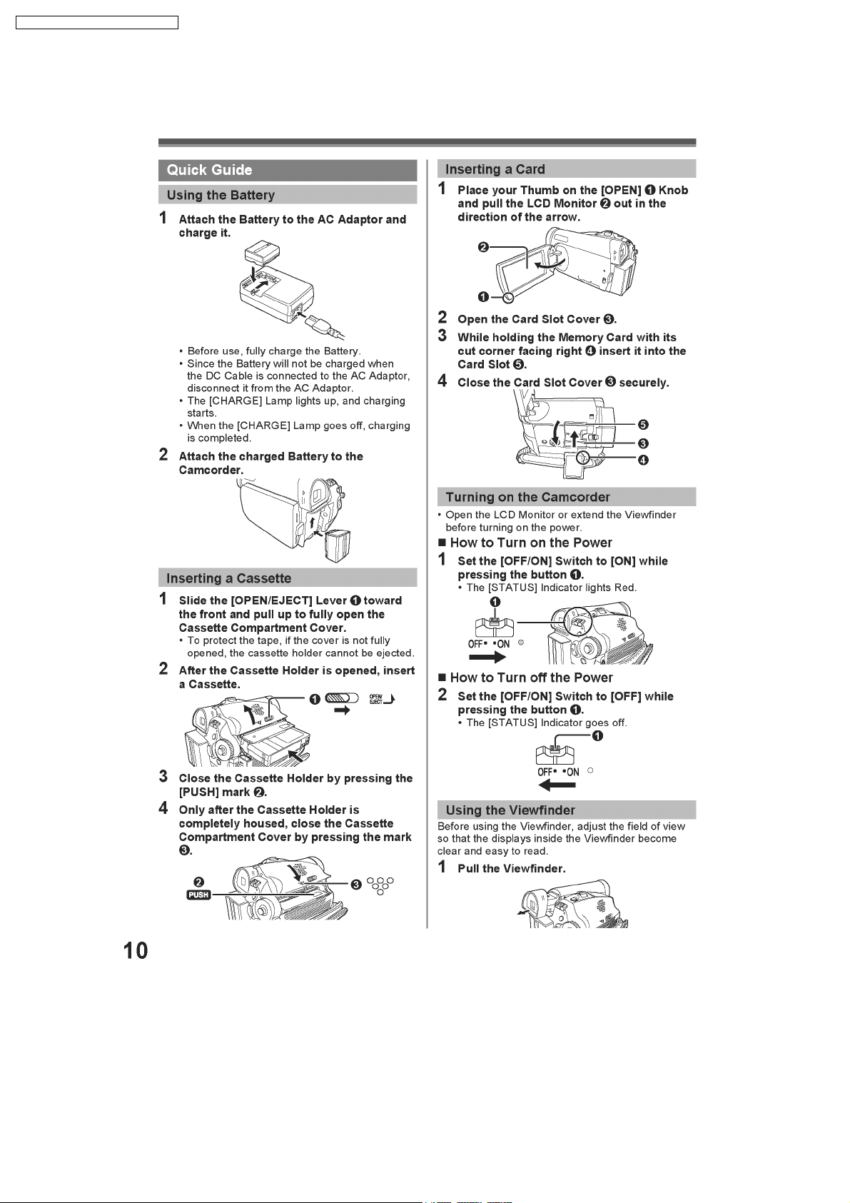
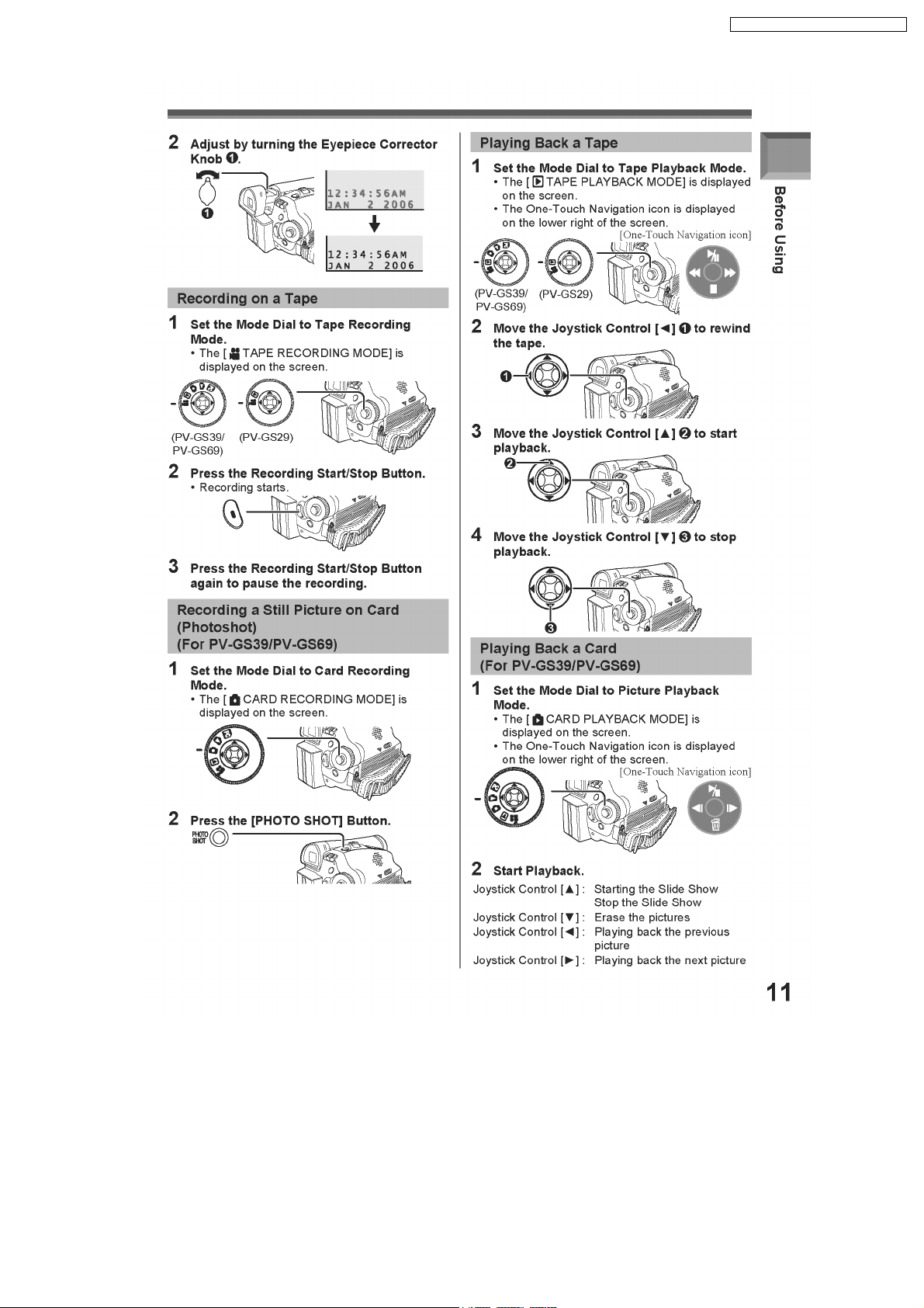
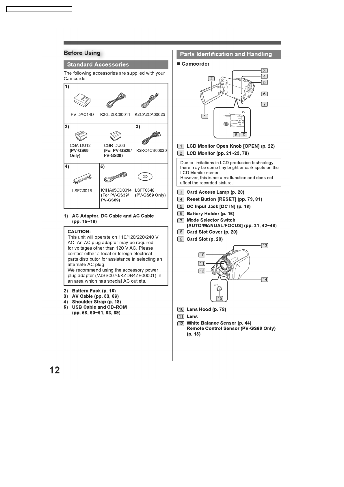
5 Location of Controls and Components
6 Service Mode
6.1. Error Display
6.2. Service Menu
7 Service Fixture & Tools
7.1. Service Fixture and Tools
7.2. Service Position
7.3. Removal/Installation of F.P.C. From Non ZIF (Zero
Insertion Force) Connector
7.4. Method for Loading/Unloading of Mechanism
7.5. EEPROM Data
7.6. Replacement Procedures for CSP (Chip Size Package) IC
7.7. Special Note
8 Disassembly and Assembly Instructions
8.1. Cabinet Section
8.2. Mechanism Section
9 Measurements and Adjustments
9.1. Mechanical Adjustment
9.2. Electrical Adjustment
10 Maintenance
10.1. Cleaning Lens, Viewfinder and LCD Panel
10.2. How to use the DVC Head Cleaning Tape / VFK1451
11 Block Diagrams
12 Schematic Diagrams
29
29
29
31
31
33
35
36
36
37
43
44
44
67
71
71
73
75
75
75
77
91
3
4
4
4
5
6
6
6
7
8
12.1. SCHEMATIC DIAGRAM & CIRCUIT BOARD LAYOUT
NOTES
12.2. MAIN SCHEMATIC DIAGRAMS
12.3. CAMERA SCHEMATIC DIAGRAM
12.4. FRONT SCHEMATIC DIAGRAM
12.5. LCD BACKLIGHT SCHEMATIC DIAGRAM (Model: PV-
GS29PL)
12.6. LCD BACKLIGHT SCHEMATIC DIAGRAM (Models: PV-
GS39PL/PV-GS69PL)
12.7. EVF BACKLIGHT / CASSETTE COVER / BATTERY
CASE SCHEMATIC DIAGRAMS
12.8. CCD / REAR / LCD SW SCHEMATIC DIAGRAMS
12.9. INTERCONNECTION SCHEMATIC DIAGRAM
12.10. VOLTAGE CHART
13 Printed Circuit Board
13.1. MAIN P.C.B.
13.2. CAMERA P.C.B.
13.3. FRONT P.C.B.
13.4. LCD BACKLIGHT P.C.B. (Model: PV-GS29PL)
13.5. LCD BACKLIGHT P.C.B. (Models: PV-GS39PL/PV-
GS69PL)
14 Appendix Information of Schematic Diagram
14.1. CHECKING POINT TABLE OF THE CSP IC
14.2. WAVEFORM TABLE
15 Exploded Views
15.1. MAIN PARTS SECTION
15.2. FRONT AND BOTTOM CASE SECTION
15.3. SIDE CASE R AND LCD SECTION
15.4. CCD AND LENS SECTION
15.5. EVF SECTION
15.6. MECHANISM SECTION
15.7. PACKING PARTS AND ACCESSORIES SECTION
16 Replacement Parts Lists
16.1. MECHANICAL REPLACEMENT PARTS LIST
16.2. ELECTRICAL REPLACEMENT PARTS LIST
91
92
106
111
112
113
114
115
116
117
123
123
126
128
129
130
131
131
138
141
141
142
143
145
146
147
148
149
149
151
2

1 Safety Precautions
1.1. General Guidelines
1. IMPORTANT SAFETY NOTICE
There are special components used in this equipment
which are important for safety. These parts are marked by
in the Schematic Diagrams, Circuit Board Layout,
Exploded Views and Replacement Parts List. It is essential
that these critical parts should be replaced with
manufacturer’s specified parts to prevent shock, fire, or
other hazards. Do not modify the original design without
permission of manufacturer.
2. An Isolation Transformer should always be used during the
servicing of AC Adaptor whose chassis is not isolated from
the AC power line. Use a transformer of adequate power
rating as this protects the technician from accidents
resulting in personal injury from electrical shocks. It will also
protect AC Adapto r from being damaged by accidental
shorting that may occur during servicing.
3. When servicing, observe the original lead dress. If a short
circuit is found, replace all parts which have been
overheated or damaged by the short circuit.
4. After servicing, see to it that all the protective devices such
as insulation barriers, insulation papers shields are properly
installed.
5. After servicing, make the following leakage current checks
to prevent the customer from being expose d to shock
hazards.
PV-GS29PL / PV-GS 39PL / PV-GS69 PL
3
PV-GS29PL / PV-GS 39PL / PV-GS69 PL
2 Warning
2.1. Prevention of Electro Static Discharge (ESD) to Electrostatically
Sensitive (ES) Devices
Some semiconductor (solid state) devices can be damaged easily by static electricity. Such components commonly are called
Electrostatically Sensitive (ES) Devices. Examples of typical ES devices are integrated circuits and some field-effect transistors and
semiconductor "chip" components. The following techniques should be used to help reduce the incidence of component damage
caused by electro static discharge (ESD).
1. Immediately before handlin g any semiconductor component or semiconductor-equipped assembly, drain off any ESD on your
body by touching a known earth ground. Alternatively, obtain and wear a commercially available discharging ESD wrist strap,
which should be removed for potential shock reasons prior to applying power to the unit under test.
2. After removing an electrical assembly equipped with ES devices, place the assembly on a conductive surface such as
aluminum foil, to prevent electrostatic charge buildup or exposure of the assembly.
3. Use only a grounded-tip soldering iron to solder or unsold er ES devices.
4. Use only an antistatic solder removal device. Some solder removal devices not classified as "antistatic (ESD protected)" can
generate electrical charge sufficient to damage ES devices.
5. Do not use freon-propelled chemicals. These can generate electrical charges sufficient to damage ES devices.
6. Do not remove a replacement ES device from its protective package until immediately before you are ready to install it. (Most
replacement ES devices are packaged with leads electrically shorted together by conductive foam, aluminum foil or comparable
conductive material).
7. Immediately before removing the protective material from the leads of a replacement ES device, touch the protective material
to the chassis or circuit assembly into which the device will be installe d.
CAUTION :
Be sure no power is applied to the chassis or circuit, and observe all other safety precautions.
8. Minimize bodily motions when handling unpackaged replacement ES devices. (Otherwise harmless motion such as the
brushing together of your clothes fabric or the lifting of your foot from a carpeted floor can generate static electricity (ESD)
sufficient to damage an ES device).
2.2. How to Recycle the Lithium Battery
4

PV-GS29PL / PV-GS 39PL / PV-GS69 PL
2.3. How to Replace the Lithium Battery
The lithium battery (ML-621S/F9D) is not supplied as a service part and must be replaced as part of the Cassette Cover Unit. (Refer
to “Disassembly and Assembly Instructions.")
NOTE:
This Lithium battery is a critical component. (Type No.: ML-621S/F9D Manufactured by Panasonic.) (Not supplied)
It must never be subjected to excessive heat or discharge.
It must therefore only be fitted in equipment designed specifically for its use.
Replacement batteries must be of the same type and manufacture.
They must be fitted in the same manner and location as the original battery, with the correct polarity contacts observed.
Do not attempt to re-charge the old battery or re-use it for any other purpose.
It should be disposed of in waste products destined for burial rather than incineration.
5

PV-GS29PL / PV-GS 39PL / PV-GS69 PL
3 Service Navigation
3.1. Introduction
This service manual contains technical information which will allow service personnel´s to understand and service this model.
Please place orders using the parts list and not the drawing reference numbers.
If the circuit is changed or modified, this information will be followed by supple ment service manua l to be filed with original service
manual.
Note 1:
AC Adaptor used on these movie camera is PV-DAC14D. However, DE-974FA is supplied as a replacement part for PVDAC14D. This AC Adaptor is supplied only as a unit.
3.2. About Lead Free Solder (PbF)
6

4 Specifications
PV-GS29PL / PV-GS 39PL / PV-GS69 PL
7
PV-GS29PL / PV-GS 39PL / PV-GS69 PL
5 Location of Controls and Components
8
PV-GS29PL / PV-GS 39PL / PV-GS69 PL
9
PV-GS29PL / PV-GS 39PL / PV-GS69 PL
10

PV-GS29PL / PV-GS 39PL / PV-GS69 PL
11
PV-GS29PL / PV-GS 39PL / PV-GS69 PL
12

PV-GS29PL / PV-GS 39PL / PV-GS69 PL
13

PV-GS29PL / PV-GS 39PL / PV-GS69 PL
14
PV-GS29PL / PV-GS 39PL / PV-GS69 PL
15

PV-GS29PL / PV-GS 39PL / PV-GS69 PL
16

PV-GS29PL / PV-GS 39PL / PV-GS69 PL
17

PV-GS29PL / PV-GS 39PL / PV-GS69 PL
18

PV-GS29PL / PV-GS 39PL / PV-GS69 PL
19
PV-GS29PL / PV-GS 39PL / PV-GS69 PL
20

PV-GS29PL / PV-GS 39PL / PV-GS69 PL
21
PV-GS29PL / PV-GS 39PL / PV-GS69 PL
22
PV-GS29PL / PV-GS 39PL / PV-GS69 PL
23

PV-GS29PL / PV-GS 39PL / PV-GS69 PL
24

PV-GS29PL / PV-GS 39PL / PV-GS69 PL
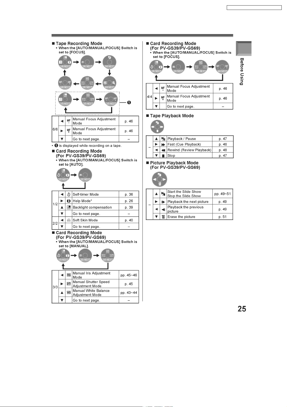
25
PV-GS29PL / PV-GS 39PL / PV-GS69 PL
26

PV-GS29PL / PV-GS 39PL / PV-GS69 PL
27

PV-GS29PL / PV-GS 39PL / PV-GS69 PL
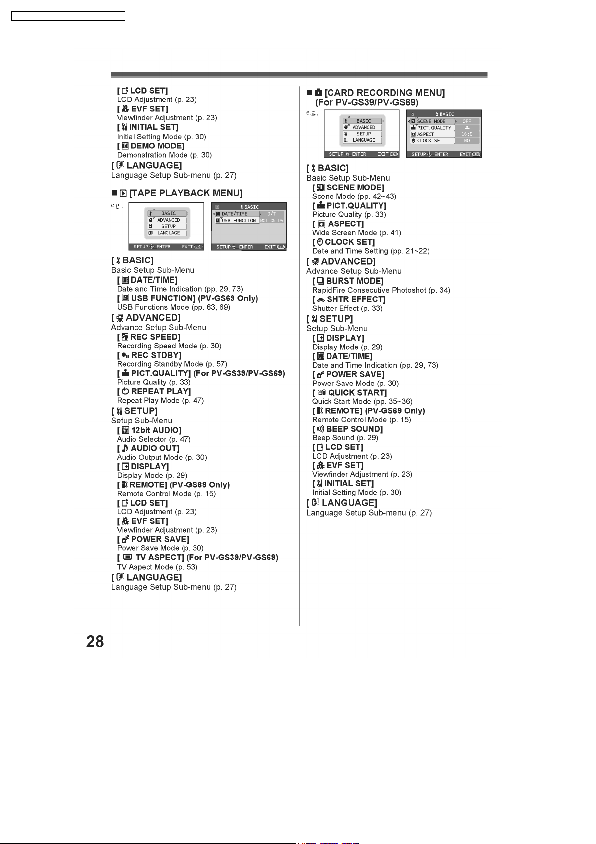
28
PV-GS29PL / PV-GS 39PL / PV-GS69 PL
6 Service Mode
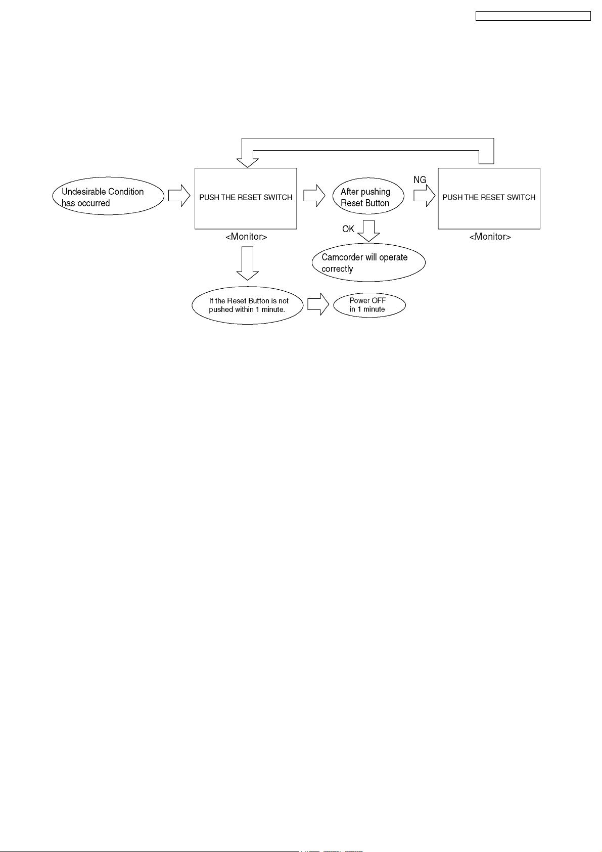
6.1. Error Display
"PUSH THE RESET SWITCH" is displayed automatically on the EVF or the LCD Monitor when an undesirable condition has
occurred.
Fig. 1
Note:
When "PUSH THE RESET SWITCH" is displayed repeatedly, service is required. Check the Error Code which is listed in the
Service Menu.
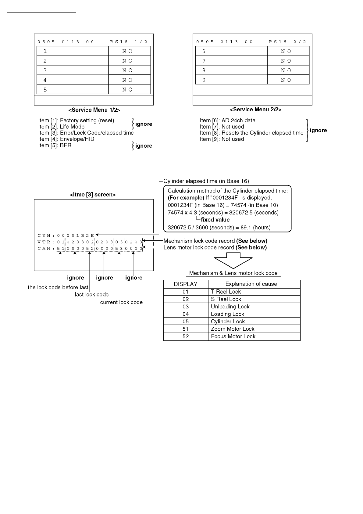
6.2. Service Menu
When abnormal detection contents are confirmed, do the following operation. Automatic diagnosis code will be displayed. (Service
Menu)
To enter the Service Menu
Push the [PHOTO SHOT], [JOYSTICK CONTROL LEFT] and [RECORDING START /STOP] simultaneously for 3 seconds (with
no SD Card inserted).
Note:
If a Disc or SD Card is inserted, the above operation will not work.
This operation displays the following Service Menu items.
To select the Item
1. Set to Service Menu.
2. Press the [JOYSTICK CONTROL UP/DOWN] to select item [3].
3. Press the [JOYSTICK CONTROL RIGHT] to display [YES/NO] screen.
4. Press the [JOYSTICK CONTROL UP/DOWN] to select [YES].
5. Press the [JOYSTICK CONTROL CENTER].
Note:
Only perform items 3 in the Service Menu.
To exit the Service Menu
Unplug the AC Cord.
29
PV-GS29PL / PV-GS 39PL / PV-GS69 PL
Fig. 2
30
 Loading...