

Page 1
Manufactured by:
81-IN3032-9922
Before attempting to connect or operate this product, please read these instructions completely.
for
MODEL: Indoor Ceiling Housing
PID8
NOTE: Max. storage space is 8"
(Panasonic 1/3" Camera Class with
Panasonic Fixed Focal Lens Series
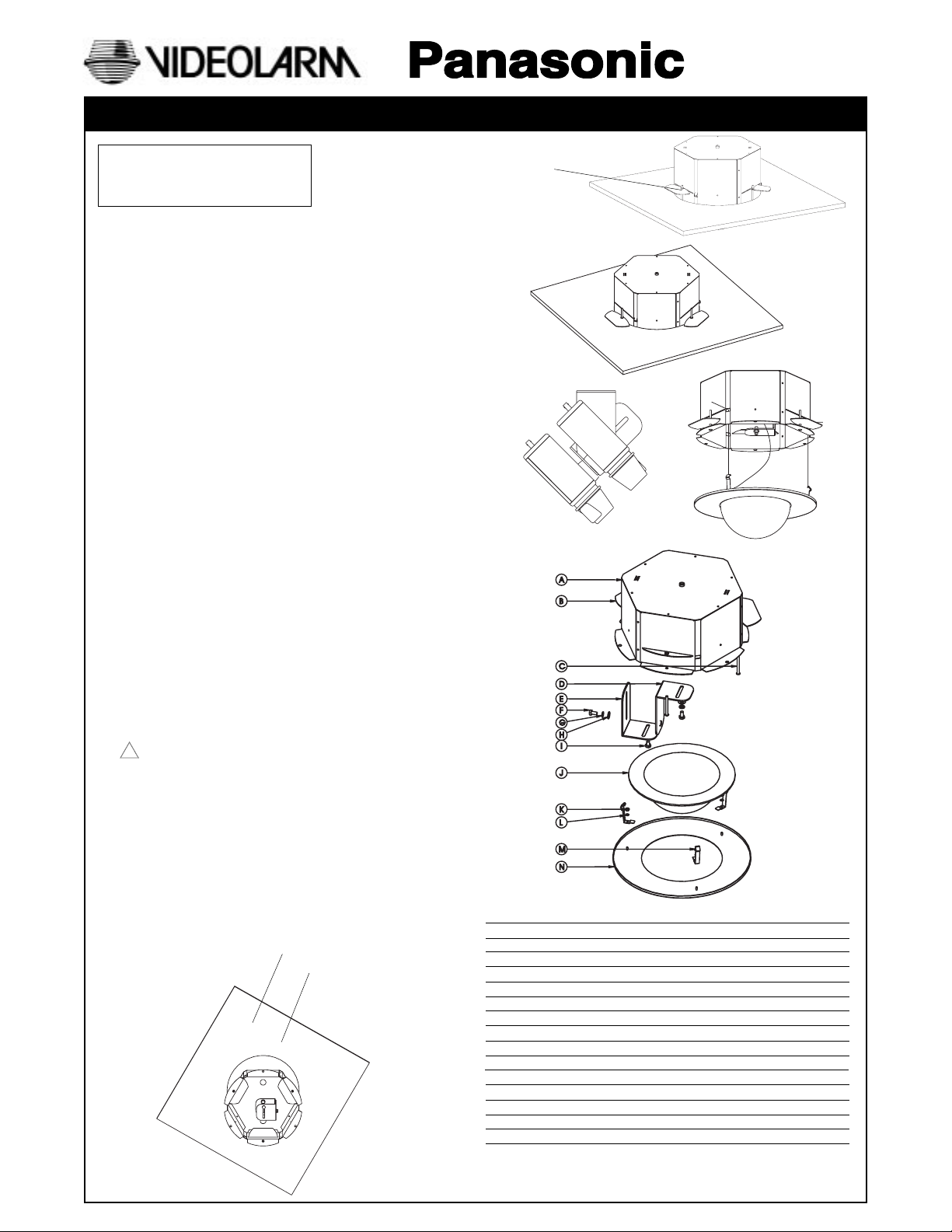
STANDARD INSTALLATION PROCEDURE
1. Carefully remove all equipment from the box.
2. Cut a 11.125" hole into the ceiling in the desired spot.
3. Remove the desired conduit knock-out from the top of
the PID8 housing.
4. Remove the trim ring and dome by pulling on the outside
of the trim ring. The ring and dome, are connected by
three flat springs, which press against the side of the
housing and lock into (3) cutouts.
5. With the support arms (3) rotated to the inside, slide the
housing into the pre-cut hole (Figure 1).
6. With the bottom flange pressed up against the ceiling,
rotate the support arms to the outside, the arms will fall to
the back side of the ceiling. Tighten the (3) support arm
screws.
7. If the housings is going into a ceiling where the support
arms will not work, the housing can be secured to the
ceiling by running bolts through the bottom flange into
the solid ceiling.
8. Connect support wires to the top of the housing through
the two provided slots.
9. Run electrical cable into the housing through the conduit
knock-out.
10. The camera can be mount on either side of the tilt part of
the camera bracket (Figure 4).
Use with Class 2 Power Supply only.
!
11. Complete all electrical connections, and adjust the
camera to the proper angle.
12. Reattach dome and faceplate by pressing in and sliding
the three flat springs into the housing, make sure the
springs are aligned with the three spring slots. You will feel
all three springs snap into place when the dome is correctly
secured into place.
13. Adjust the drop-in-liner so that the viewing slot is in the
proper position.
Mounting holes
Support arm screws
PRODUCT INSTRUCTIONS
Support arms
rotated out
Figure 2
Figure 3
Figure 5
Figure 4
Figure 6
Description Part number Qty.
A PID8 Top housing 30-VL1240 1
B PID8 Support arms 30-VL1208 3
C 10-24 x 2.0" SS pan head screw 90-BTSR23 3
D Camera bracket part B 30-VL1210 1
E Camera bracket 30-VL1209 1
F 1/4-20x3/8" Hex head bolt 90-BTHH28 2
G 1/4 SAE Flat washer 92-WSFL01 2
H 1/4 Split lockwasher 92-WSSL01 2
I 1/4-20x3/8"" hex head bolt 90-BTHH28 1
J 7" Tinted capsule w/ drop in liner RCMR7T 1
K 6-32 Hex nut SS 91-NTHH04 3
L #6 Star washer 92-WSTH01 3
M PID8 Spring clip 30-VL1222 3
N PID8 White trim ring 30-VL1206 1
NS 7" Molded line 20-DTMR7 1
Figure 1
Page 2
1. Read Instructions - All the safety and operating instructions
!
should be read before the unit is operated.
2. Retain Instructions - The safety and operating instructions
should be retained for future reference.
3. Heed Warnings - All warnings on the unit and in the operating
instructions should be adhered to.
4. Follow Instructions - All operating and user instructions should
be followed.
5. Electrical Connections - Only a qualified electrician should
make electrical connections.
6. Attachments - Do not use attachments not recommended by the
product manufacturer as they may cause hazards.
7. Cable Runs - All cable runs must be within permissible distance.
8. Mounting - This unit must be properly and securely mounted to
a supporting structure capable of sustaining the weight of the
unit. Accordingly:
a. The installation should be made by a qualified service
person, and should conform to all local codes.
b. Care should be exercised to select suitable hardware to
install the unit, taking into account both the composition of the
mounting surface and the weight of the unit. Be sure to
periodically examine the unit and the supporting structure to
make sure that the integrity of the installation is intact. Failure
to comply with the foregoing could result in the unit separating
from the support structure and falling, with resultant damages
or injury to anyone or anything struck by the falling unit.
SAFETY PRECAUTIONSIMPORTANT SAFEGUARDS
CAUTION
RISK OF
ELECTRIC SHOCK!
CAUTION: TO REDUCE THE RISK OF
ELECTRICAL SHOCK, DO NOT EXPOSE
COMPONENTS TO WATER OR MOISTURE.
The lightning flash with an arrowhead symbol,
within an equilateral triangle, is intended to
alert the user to the presence of non-insulated
"dangerous voltage" within the product's
enclosure that may be of sufficient magnitude
to constitute a risk of electric shock to persons.
The exclamation point within an equilateral
triangle is intended to alert the user to
!
UNPACKING
Unpack carefully. Electronic components can be
damaged if improperly handled or dropped. If an item
appears to have been damaged in shipment, replace it
properly in its carton and notify the shipper.
presence of important operating and
maintenance (servicing) instructions in the
literature accompanying the appliance.
Be sure to save:
1. The shipping carton and packaging material. They are the
safest material in which to make future shipments of the
equipment.
2. These Installation and Operating Instructions.
SERVICE
For service on Panasonic/Videolarm equipment contact:
Panasonic Technical Center
54 West Gude Dr.
Rockville MD 20850-1150
Phone: 301-762-5125
Fax: 301-251-0347
PANASONIC TECHNICAL SUPPORT
1-800-528-6747
9:00 AM - 5:00 PM EASTERN TIME
- 2 -
 Loading...