

Page 1
Product
Instructions
Indoor Ceiling Housing
PID5CN
Manufactured by
Before attempting to connect or operate this product,
please read these instructions completely.
for
81-IN3089
10/16/06
Page 2
MODEL: Indoor Ceiling Housing
PID5
PRODUCT INSTRUCTIONS
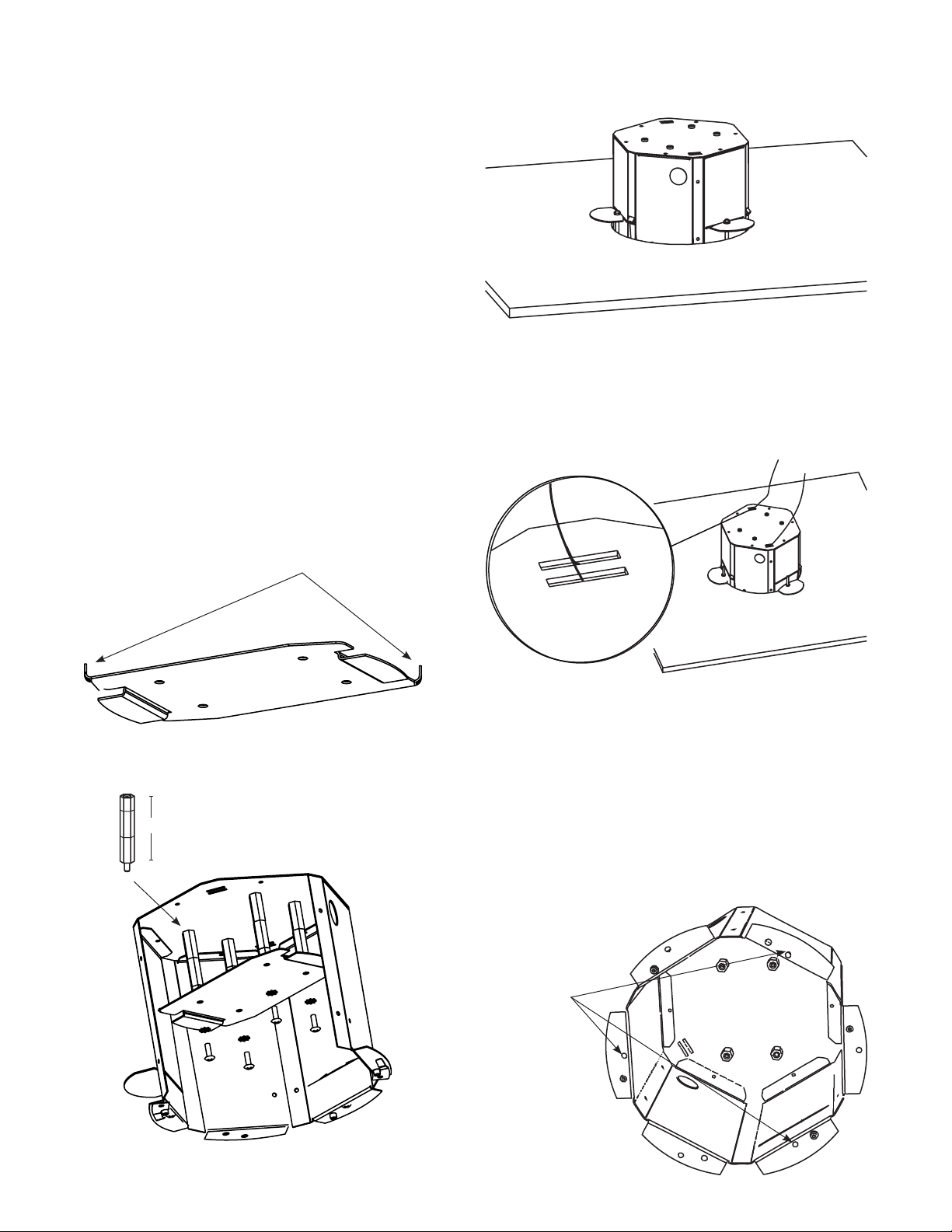
6. With the support arms (3) rotated to the inside, slide the
housing into the pre-cut hole (Figure 3).
Before attempting to connect or operate this product, please
read these instructions completely.
• This product has been designed and engineered for the
unitized camera(s) WV-NS202 & CF-284, CW-484 for ease
of installation and service.
• This product is a discreet indoor recessed surveillance
enclosure designed to mount into a drop ceiling tile or sheet
rock ceiling.
• This unit completely encloses the unitized camera resulting
in discreet viewing.
STANDARD INSTALLATION PROCEDURE WV-NS202
1. Carefully remove all equipment from the box.
2. Using the template provided, cut a 7.5” hole into the ceiling
in the desired spot. (See #8 below for special note)
3. Remove the desired conduit knockout from the side of the
PID5 housing.
4. Detach the camera mounting base from the camera and
mount it to the PID5 housing using 2½" of spacers as shown.
5. Before camera mounting plate can be installed in housing,
tabs must be bent as a shown below (Figure 1).
Figure 1
Bend Down Tabs
Figure 3
7. With the bottom ange pressed up against the ceiling,
rotate the support arms to the outside, the arms will fall to
the back side of the ceiling (Figure 3). Tighten the (3) 8-32 x
1½” Phillips screws (Figure 5).
8. Support wires (not provided) must be connected to the top
of the housing through the two provided slots (Figure 4).
2½"
spacer
Figure 4
CAUTION: The wires must be able to support
up to 15 lbs (6.8 kg).
9. If the housing is going into a ceiling where the support arms
will not work, the housing can be secured to the ceiling by
running bolts (not provided) through the bottom ange into
the solid ceiling (Figure 5).
NOTE: If you use bolts instead of support wires the
hole will need to be the same size and shape
as the top of the housing. DO NOT USE THE
7.5” TEMPLATE. Use the top of the housing as a
template to cut
out the hole.
Use to attach
housing to
solid ceiling
Figure 5
Figure 2
- 2 -
Page 3

WV-NS202 CAMERA INSTALLATION
Use with Class 2 Power Supply only.
!
10. Run electrical cable into the housing through one of the
three conduit knockouts.
11. Complete all electrical and video connections.
12. Attach the WV-NS202 camera to the camera mounting
base and secure with the safety screw provided with the
camera (Figure 6).
Figure 6
WV-NF284 AND WV-CW484 CAMERA INSTALLATION
1. This enclosure can also be used to mount the WV-NF284 and
WV-CW484 cameras. Spacers are included inthe housing
packet to properly position the cameras within the housing.
See the Figure below for the correct spacing.
3.500
SPACERS
WV-NF284
4.000
SPACERS
WV-CW484
2. Once spacers are installed follow the same procedure as
mentioned above for installing the enclosure in the ceiling.
NOTE: The WV-NF284 and the WV-CW484 do not use
the installed dome. For these products it is necessary to
remove the dome and replace with insert provided in
housing packet.
Adding Insert
- 3 -
Page 4

13. Reattach the PID5 dome by pressing in and twisting the
two at spring clips into the housing (Figure 7).
Figure 7
- 4 -
Page 5

SPECIFICATIONS
3.287
1.811
O 7.650
6.650
7.310
3.287
1.811
O 7.650
6.650
7.310
1.200
8.373
.340
Metal Back Box 0000000000 18 and 20-gauge steel,
000000000000000000000000 w/black powdercoat nish
Support Arms 000000000000 18-gauge Galvanized steel
Decorative Trim Ring 000000 ABS Plastic
Electrical Input 00000000000 (3) .875" knockouts
Unit Weight 00000000000000 3.5 lbs. (1.6 kg)
.
.
.
.
1
EXPLODED VIEW
1. 00 PID9 Housing
2. 00 (3) Support Arms
3. 00 Trim Ring
4. 00 Packet Assembly
5. 00 Dome
2
RP-PID9-1000
RP-PID9-1010
RP-PID9-1020
RP-PID9-1025
RC5
.
.
.
DIMENSIONS
.
.
3
- 5 -
Page 6
1. Read Instructions - All the safety and operating instructions
should be read before the unit is operated.
2. Retain Instructions - The safety and operating instructions
should be retained for future reference.
3. Heed Warnings - All warnings on the unit and in the operating
instructions should be adhered to
4. Follow Instructions - All operating and user instructions should
be followed.
5. Electrical Connections - Only a qualified electrician should
make electrical connections
6. Attachments - Do not use attachments not recommended by the
product manufacturer as they may cause hazards
7. Cable Runs -All cable runs must be within permissible distance
8. Mounting - This unit must be properly and securely mounted to
a supporting structure capable of sustaining the weight of th e
unit. Accordingly:
a. The installation should be made by a qualified service person
and should conform to all local codes.
b. Care should be exercised to select suitable hardware to install
the unit, taking into account both the composition of the
mounting surface and the weight of the unit. Be sure to
periodically examine the unit and the supporting structure to
make sure that the integrity of the installation is intact. Failure
to comply with the foregoing could result in the unit separating
from the support structure and falling, with resultant damages
or injury to anyone or anything struck by the falling unit.
SAFETY PRECAUTIONSIMPORTANT SAFEGUARDS
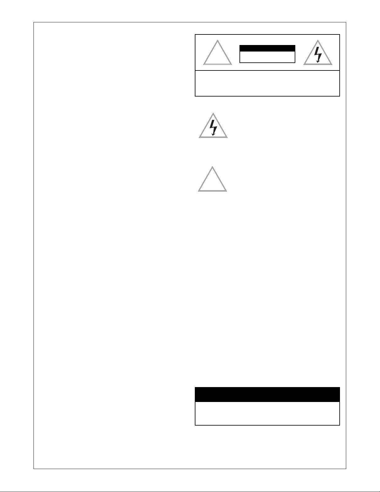
CAUTION
RISK OF
!
CAUTION: TO REDUCE THE RISK OF
ELECTRICAL SHOCK, DO NOT EXPOSE
COMPONENTS TO WATER OR MOISTURE .
!
UNPACKING
Unpack carefully. Electro nic componen ts can be
damaged if improperly handled or dropped. If an item
appears to have been damaged in shipment, replace it
properly in its carton and notify the shipper
ELECTRIC SHOCK!
The lightning flash with an arrowhead symbol,
within an equilateral triangle, is intended to
alert the user to the presence of non-insulated
"dangerous voltage" within the product's
enclosure that may be of sufficient magnitude
to constitute a risk of electric shock to persons
The exclamation point within an equilateral
triangle is intended to alert the user to
pr esenc e of im porta nt oper ating and
maintenance (servicing) instructions in the
literature accompanying the appliance
Be sure to save :
1. The shipping carton and packaging material. They are the
safest material in which to make future shipments of the
equipment.
2. These Installation and Operating Instructions
SERVICE
For service on Panasonic/Videolarm equipment contact:
Panasonic Technical Center
54 West Gude Dr
Rockville MD 20850-1150
Phone: 301-762-5125
Fax: 301-251-0347
PANASONIC TECHNICAL SUPPORT
1-800-528-6747
9:00 AM - 5:00 PM EASTERN TIME
- 6 -
 Loading...