

Page 1
Support Frame
Manufactured by:
81-IN3055-9922
Before attempting to connect or operate this product, please read these instructions completely.
for
MODEL: PDM4
Drop Ceiling Mount Bracket
DESCRIPTION
• This product has been designed and engineered for the
unitized camera WV-CS854 for ease of installation and
service.
• This product is a discreet indoor surveillance enclosure
designed to mount into a standard 2' x 2' or 2' x 4'
suspended ceiling, and can be used alone or in conjunc tion with the entire ceiling tile.
• This unit completely encloses the unitized camera
WV-CS854, resulting in discreet viewing.
INSTALLATION
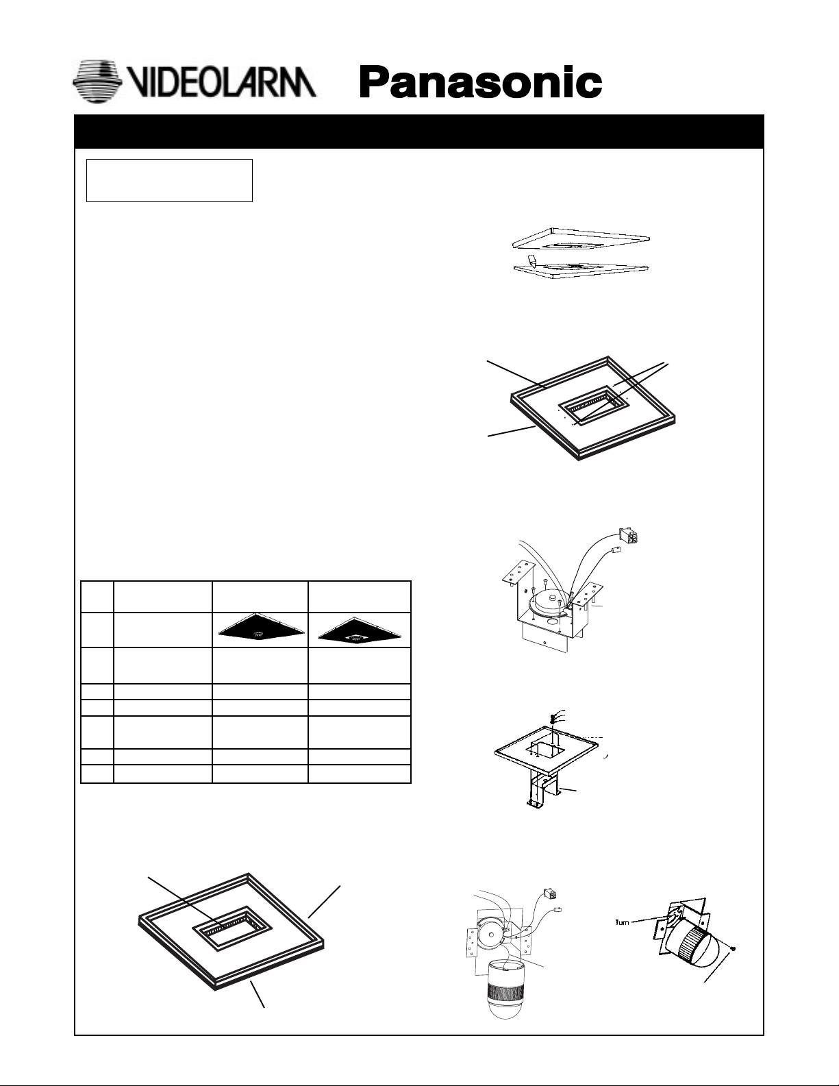
• Check all contents before beginning installation
1. Decorative ring cover
2. Metal ceiling frame
3. Support frame
4. Top cover box
5. 8 x 32 x 1/2" bolts - 2 pcs. for top cover (F)
6. 8 x 32 x 1/2" bolts - 4 pcs. for camera mounting
base (A)
7. 1/4 x 20 Nuts - 4 pcs. (D)
8. 1/4" Plane washer for support frame - 4 pcs. (B)
9. 1/4" Lock washer for support frame - 4 pcs. (C)
10. Push fastener for support frame - 2 pcs. (short), 2 pcs.
(long) (E)
PRODUCT INSTRUCTIONS
B. After making the hole, align the units so that they are
centered to one another. Adhere the two together with
a silicone adhesive or any acceptable bonding agent.
C. Make 9/32" diameter holes through the (4) holes for the
support frame. Make 0.218" diameter holes through the
(2) threaded inserts in the ceiling frame for the decora tive ring.
Frame
Tile
3-2. CAMERA INSTALLATION
A. Attach camera mounting base of the unitized camera
to the support frame using the provided 8-32 x 1/2" screw
(A).
Drill Holes
INSTALLATION STEPS
Step Item Use With Tile Use W/Provided
Frame
Tile and
3-1
Frame Not Required
Camera ••
3-2
Mounting ••
3-3
Dome &
3-4
Decorative Ring • •
Electrical ••
3-5
Top Cover ••
3-6
3-1 TILE INSTALLATION
NOTE: If you use the metal ceiling frame only, this step is
not required. Start at step 3-2.
A. Place the metal ceiling frame on top of the ceiling tile
and cut it out with a utility knife.
Cut with utility knife
Metal Ceiling Frame
B. Attach the support frame to the metal ceiling frame
using the plane washer (B), the lock washer (C), and the nut
(D).
1/4" x 20 Nuts (4)
1/4" Lock washers (4)
1/4" Plane washers (4)
Metal Ceiling Frame
Support Frame
C. Attach the safety wire to the camera mounting base,
then attach the unitized camera to the camera bracket.
Attach the safety screw to the camera mounting base
using the standard screw (G).
Ceiling Tile
(not provided)
Safety Wire
Supplied with camera
Page 2
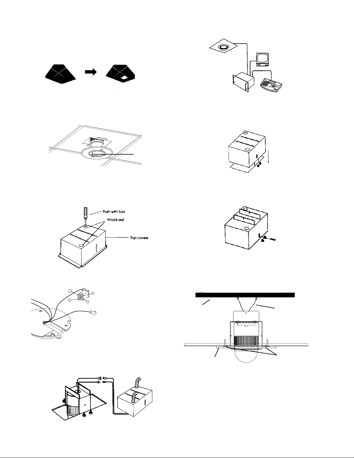
3-3 MOUNTING INSTALLATION (Dropped Ceiling)
IMPORTANT NOTE: When installing the enclosure in a 2' x 4'
ceiling, cut the ceiling tile 2' x 2' (half)
and install an additional "T" grid for
support.
A. Determine the location for mounting the enclosure.
B. Assemble the power cable with the provided connector.
(See operating instructions for the WV-CS854)
3-4 DECORATIVE RING INSTALLATION
A. Install the decorative ring using the push fastener (E). Use
the 2 larger push screws when using tile.
Push Fastener (E)
3-5 CONNECTION
A. Before connecting the cable, remove the knockout that is
in the top cover. Choose the knockout which best suits your
needs. This knockout should be used to install a conduit
connector for routing of power and video cable.
3-6 TOP COVER
A. Attach the top cover over the main support frame. Make
sure that you align the (2) horizontal slots in the top of the box
with the (2) vertical tabs on the support frame.
B. Secure the top cover box to the main support frame by
using the 8 x 32 x 1/2" 12mm bolts, flat washers, and lock
washers provided. These bolts should be inserted into the
two slots found on the side of the top cover.
C. Connect the support wires from the (2) tabs coming out of
the top cover box to a support structure about the ceiling.
B. Assemble the power cable with the provided connector.
(See operating instructions for the WV-CS854)
4
2
Front view of the male connec-
3
tor in the camera cable. Pin 1 is
1
in the lower left hand corner.
Connector Information
Pin
1. AC24V AC Live
2. AC24V AC Neutral
3. Ground
4. Not used
C. Connect the power cable and the video connector.
NOTE: These cables should be through the knockout on the
top cover.
NOTE: The support wire (not provided) MUST be connected.
It must also be able to support the weight of the
housing to remove the load from the ceiling tile.
Support structure
Decorative ring
Wire support
Push screws
- 2 -
Page 3

Personal Computer
RS-232C Port
Printer
WJ-SX550A
Matrix Switcher
Alarm Inputs
System Status
Monitor
Max. 64 Cameras
VCR
Monitors
WV-CU550A System Controller
4. SYSTEM CONNECTION
Example 1
WV-CS854
WV-CU151/CU161
Connect the coaxial cable between the Video Output
Connector on the WV-CS854 and the Camera Input
Connector on the WV-CU151/161.
Monitor
5. SPECIFICATIONS
• Mechanical
Metal Ceiling Frame 18-gauge Galvanized steel
Top Cover 24-gauge Galvanized steel
Support Frame 16-gauge Galvanized steel
Decorative Ring Cover White plastic
Dimension See drawing
Unit Weight Drop Ceiling Mount Bracket (13 lbs)
6. OUTLINE DRAWING
EXAMPLE 2
WV-7225
WV-CS854
WV -CA51
WV-RC100
WV-CS854
Connect the coaxial cable between the Video Output
Connectors on the WV-CS854 and the Camera Input
Connectors on the WJ-FS616.
NOTE: As for the other connections in the above system
diagram, refer to the operating instructions for each
product.
EXAMPLE 3
POH1000/POH1500
WV-7260D
WV-CA50
WV-CU151/CU161
Monitor
WJ-FS616
Side View
6.5"
Top View
23.75"
1.5"
6.4"
11.6"
7.4"
6.3"
9.0"
Connect the coaxial cable between the Video Output
Connectors on the WV-CS854 and the Camera Input
Connectors on the WJ-SX550A
NOTE: As for the other connections in the above system
diagram, refer to the operating instructions for each
product.
8.15"
- 3 -
Page 4

1. Read Instructions - All the safety and operating instructions
!
should be read before the unit is operated.
2. Retain Instructions - The safety and operating instructions
should be retained for future reference.
3. Heed Warnings - All warnings on the unit and in the operating
instructions should be adhered to.
4. Follow Instructions - All operating and user instructions should
be followed.
5. Electrical Connections - Only a qualified electrician should
make electrical connections.
6. Attachments - Do not use attachments not recommended by the
product manufacturer as they may cause hazards.
7. Cable Runs - All cable runs must be within permissible distance.
8. Mounting - This unit must be properly and securely mounted to
a supporting structure capable of sustaining the weight of the
unit. Accordingly:
a. The installation should be made by a qualified service
person, and should conform to all local codes.
b. Care should be exercised to select suitable hardware to
install the unit, taking into account both the composition of the
mounting surface and the weight of the unit. Be sure to
periodically examine the unit and the supporting structure to
make sure that the integrity of the installation is intact. Failure
to comply with the foregoing could result in the unit separating
from the support structure and falling, with resultant damages
or injury to anyone or anything struck by the falling unit.
SAFETY PRECAUTIONSIMPORTANT SAFEGUARDS
CAUTION
RISK OF
ELECTRIC SHOCK!
CAUTION: TO REDUCE THE RISK OF
ELECTRICAL SHOCK, DO NOT EXPOSE
COMPONENTS TO WATER OR MOISTURE.
The lightning flash with an arrowhead symbol,
within an equilateral triangle, is intended to
alert the user to the presence of non-insulated
"dangerous voltage" within the product's
enclosure that may be of sufficient magnitude
to constitute a risk of electric shock to persons.
The exclamation point within an equilateral
triangle is intended to alert the user to
!
UNPACKING
Unpack carefully. Electronic components can be
damaged if improperly handled or dropped. If an item
appears to have been damaged in shipment, replace it
properly in its carton and notify the shipper.
presence of important operating and
maintenance (servicing) instructions in the
literature accompanying the appliance.
Be sure to save:
1. The shipping carton and packaging material. They are the
safest material in which to make future shipments of the
equipment.
2. These Installation and Operating Instructions.
SERVICE
For service on Panasonic/Videolarm equipment contact:
Panasonic Technical Center
54 West Gude Dr.
Rockville MD 20850-1150
Phone: 301-762-5125
Fax: 301-251-0347
PANASONIC TECHNICAL SUPPORT
1-800-528-6747
9:00 AM - 5:00 PM EASTERN TIME
- 4 -
 Loading...