

Panasonic PCF5, PCV5 User Manual
Manufactured by:
81-IN3050-9922
Before attempting to connect or operate this product, please read these instructions completely.
for
MODEL: Miniature Camera
PCF5, PCV5
DESCRIPTION: Surface Mount Dome Housing,
Multiple Color Cameras
STANDARD INSTALLATION PROCEDURE
INCLUDES MODELS: PCF5, PCV5
Contents include:
(1) MV5 ABS Housing
(4) Adjustable bracket arms
(4) Universal mounting plates
(1) 10" Tinted acrylic dome
Mounting hardware
(1) Camera, lens, and PC Board
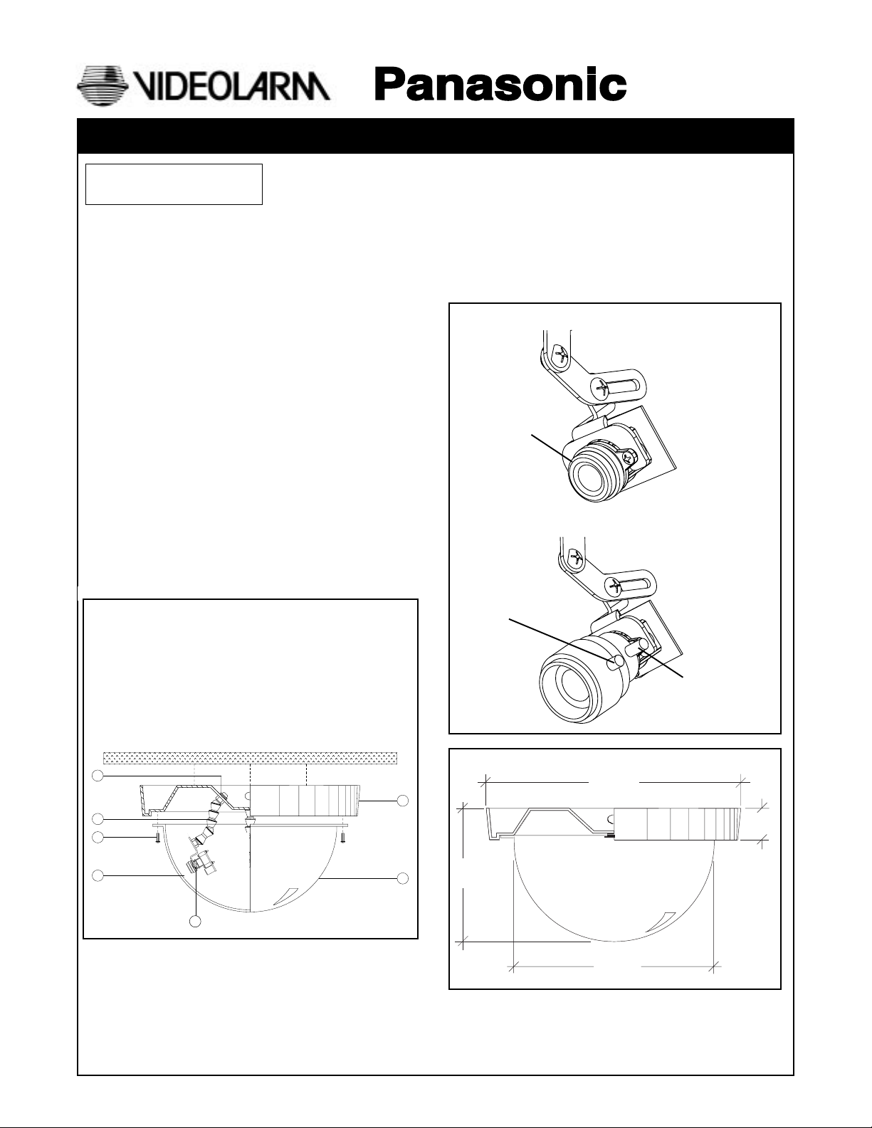
Mounting Instructions: (fig. 4)
1. Select unobstructed, level mounting surface.
2. Attach housing to the surface using appropriate
mounting hardware (not included).
3. Make final adjustments to the camera the viewing loca tions and complete all electrical connections.
4. Attach the 10" acrylic dome to the housing using the
(4) X-mas tree fasteners.
PRODUCT INSTRUCTIONS
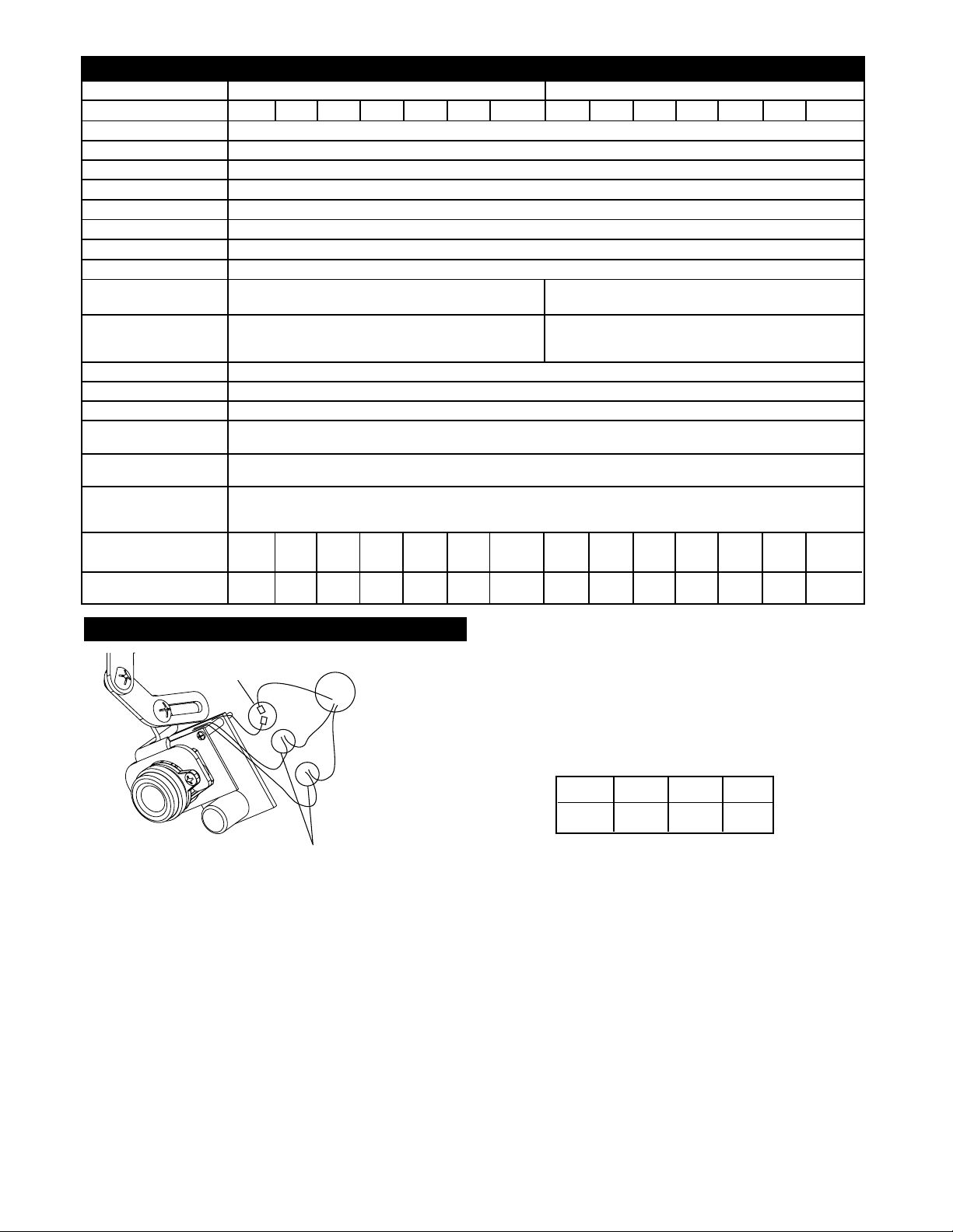
5. Fine focusing (see diagram below):
Fixed Lens: Manually rotate the lens until a clear picture is
achieved.
Vari-Focal Lens: First, adjust the Magnification Lock Screw
to the desired magnification (telephoto
to wide angle). Tighten the Lock Screw.
Next, adjust the Focus Lock Screw until a
clear picture is achieved. Tighten the
Lock Screw.
Camera Fine Focus
Fixed Lens Camera
(PCF5)
Manual focus
Vari-focal Lens Camera
(PCV5)
Parts List:
1 (8) 1/4" NPT nuts
2 (4) Adjustable bracket arms
3 (4) X-mas tree fastener
4 (4) Universal mounting plates
5 PCF5/PCV5 ABS housing
6 10" Tinted acrylic dome
7 Camera and PC Board
Mounting surface
1
2
3
4
7
Focus Lock Screw
Magnification
Lock Screw
15.9"
5
3.2"
6
8.0"
12.0"
Specification
Lens Type
Model Number
Scanning Area
Scanning
Horizontal
Vertical
Synchronization
Video Output
Horizontal Resolution
Signal-to-Noise Ratio
Minimum Illumination
Angular Field of View
Horizontal
Vertical
AGC
ELC
White Balance
Ambient Operating
Temperature
Ambient Operating
Humidity
Power Source
at AC Source
at DC Source
Dimensions
Weight
W
H
D
kg
lbs
PCF1
2.82"
4.6"
2.82"
0.68
1.5
3 - 8mm Fixed Focal Lens Series 4 - 8mm Vari- -Focal Lens Series
PCF4
PCF5
PCF3PCF2
PCF6
PCF6W
PCV3
PCV4
PCV2PCV1
PCV5
PCV6
PCV6W
361 mm (H) x 272 mm (V) (Equivalent to scanning area of 1/4" pick-up tube)
525 lines / 60 fields / 30 frames
15.734 kHz
59.94 kHz
Internal Synchronization
1.0 V (p-p) NTSC Composite 75 ohms / BNC Connector
330 lines (at center area)
46 dB (with AGC OFF)
0.5 Footcandle (5 Lux) at F2.0 0.5 Footcandle (5 Lux) at F2.0 - 1.0 Footcandle
(10 Lux) at F2.8
Horizontal 53.4˚
Horizontal 51.7 - 26.7˚
Vertical 40.0˚ Vertical 38.4 - 20.0˚
On (Preset)
On (Preset)
ATW (Preset)
-10˚C - +50˚C (14˚F - 122˚F)
Less than 90%
24 VAC, 40 ma
12 VDC, 80 ma
2.82"
6.0"
6.0"
6.0"
0.45
1
3.15"
4.9"
3.2"
0.45
1
5.25"
3.0"
3.625"
0.45
1
15.9"
11.2"
15.9"
1.8
4
6.0"
6.0"
6.0"
0.68
1.5
6.0"
10.8"
7.0"
0.91
2
4.6"
2.82"
0.68
1.5
6.0"
6.0"
6.0"
0.45
1
3.15"
4.9"
3.2"
0.45
1
5.25"
3.0"
3.625"
0.45
1
15.9"
11.2"
15.9"
1.8
4
6.0"
6.0"
6.0"
0.68
1.5
6.0"
10.8"
7.0"
0.91
2
Connections
Video
BNC Connectors
Power Connections
NOTE: Splice wiring according to
standard electrical guidlines.
Positive and Negative connections are
interchangeable with this PC Board.
CAUTION: To prevent fire or shock hazard, the UL-Listed wire
VW-1, style 1007, should be used for the cable for
24 VAC input terminals.
Wiring Chart-Cable Distance
This Chart is based on a 12VDC power supply with the
maximum Amp draw at .500 amps.
WIRE 20 18 16
FT. 180' 300' 480'
- 2 -
 Loading...