

Page 1
ORDER NO. MOD0009238C1
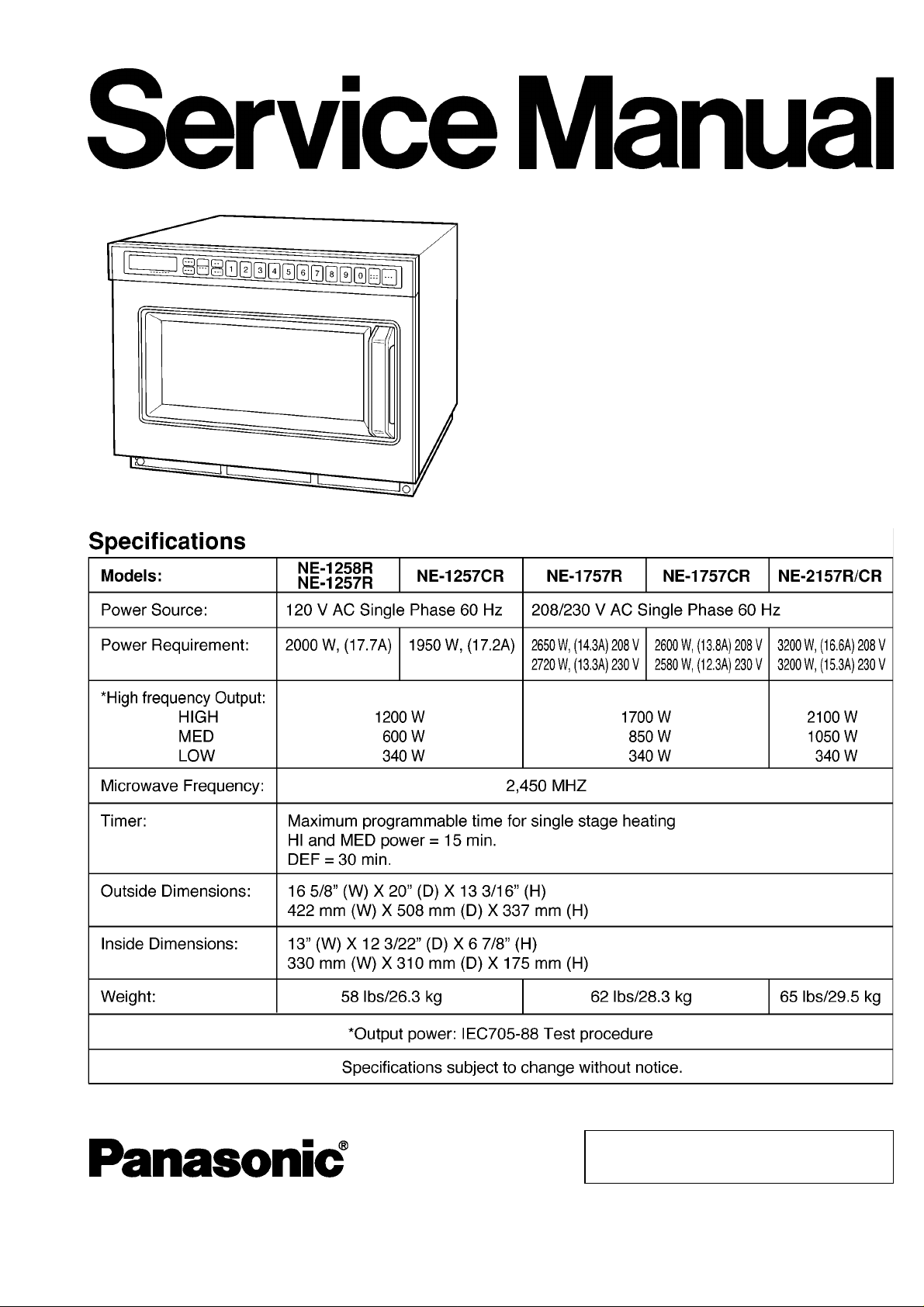
Commercial Microwave Oven
NE-1257R/NE-1257CR
NE-1757R/NE-1757CR
NE-2157R/NE-2157CR
NE-1258R
E10
© 2000 Matsushita Electric Industrial Co., Ltd. All
rights reserved. Unauthorized copying and
distribution is a violation of law.
Page 2
NE-1257R/NE-1257CR / NE-1757R/NE-1757CR / NE-2157R/NE-2157CR / NE-1258R
CONTENTS
Page Page
1 OUTLINE DIAGRAM 4
2 OPERATION PROCEDURE
3 WIRING REQUIREMENTS AND POWER SOURCE VOLTAGE
SELECTION
4 SCHEMATIC DIAGRAM (NE-1257R, NE-1258R)
5 SCHEMATIC DIAGRAM (NE-1257CR)
6 SCHEMATIC DIAGRAM (NE-1757R)
10
11
12
13
7 SCHEMATIC DIAGRAM (NE-1757CR)
8 SCHEMATIC DIAGRAM (NE-2157R)
5
9 SCHEMATIC DIAGRAM (NE-2157CR)
10 WIRING DIAGRAM (NE-1 257R, NE-1258R)
11 WIRING DIAGRAM (NE-1 257CR)
12 WIRING DIAGRAM (NE-1 757R)
13 WIRING DIAGRAM (NE-1 757CR)
2
14
15
16
17
18
19
20
Page 3

14 WIRING DIAGRAM (NE-2 15 7R) 21
15 WIRING DIAGRAM (NE-2 15 7CR )
16 DESCRIPT ION OF OPERATING SEQUENCE
17 CAUTIONS TO BE OBSERVED WHEN TROUBLESHOOTING
18 DISASSEMBLY AND PARTS REPLACEMENT PROCEDU RE
19 COMPONE NT TEST PROCEDU RE
20 MEASURE MENTS AND ADJUSTMENTS
22
23
24
26
30
32
21 PROCEDU RE FOR MEASURING MICROWAVE ENERGY
LEAKAGE
22 TROUBLE SHOOTING GUIDE
23 EXPLODED VIEW AND PARTS LIST
33
35
36
NE-1257R/NE-1257CR / NE-1757R/NE-1757CR / NE-2157R/NE-2157CR / NE-1258
24 PARTS LIST
25 DOOR ASSEMBLY
26 ESCUTCH EON BASE ASSEMBLY
27 PACKING AND ACCESSO RIES
28 WIRING MATERIAL
29 REF. NO. 89 L. V. TRANSFO RMER (U)
30 REF. NO. 58 NOISE FILTER (U)
31 REF. NO. E2 P. C. BOARD (U)
32 DIGITAL PROGRAMMER CIRCUIT
33 DIGITAL PROGRAMMER CIRCUIT
37
40
41
42
43
44
44
45
46
48
3
Page 4
NE-1257R/NE-1257CR / NE-1757R/NE-1757CR / NE-2157R/NE-2157CR / NE-1258R
1 OUTLINE DIAGRAM
4
Page 5
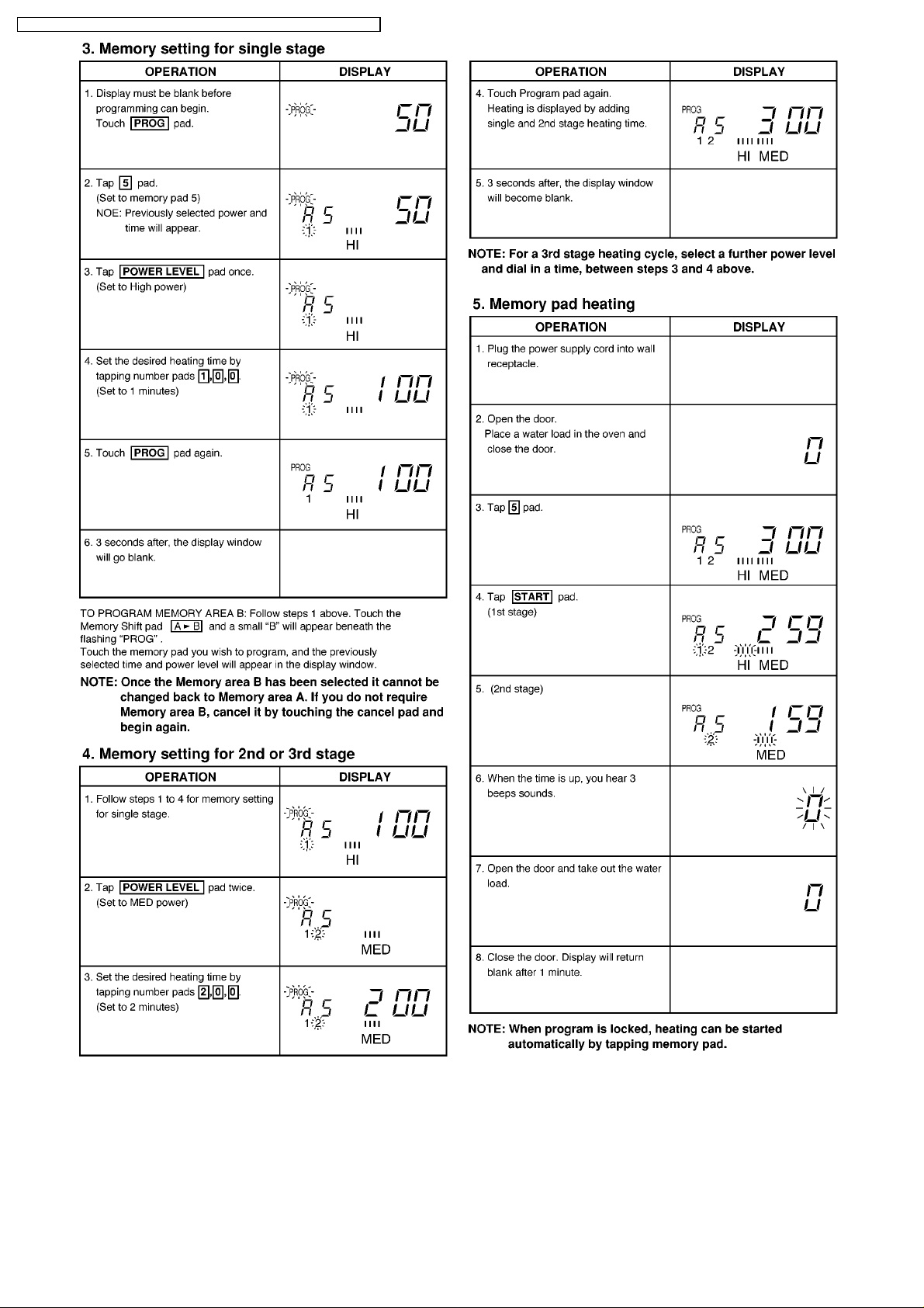
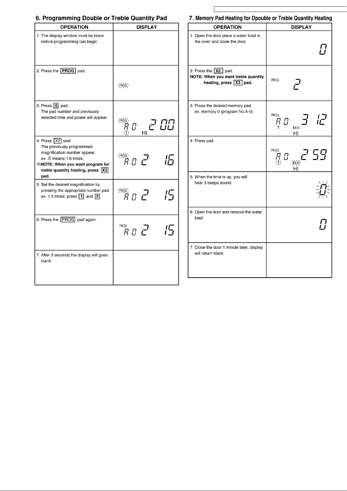
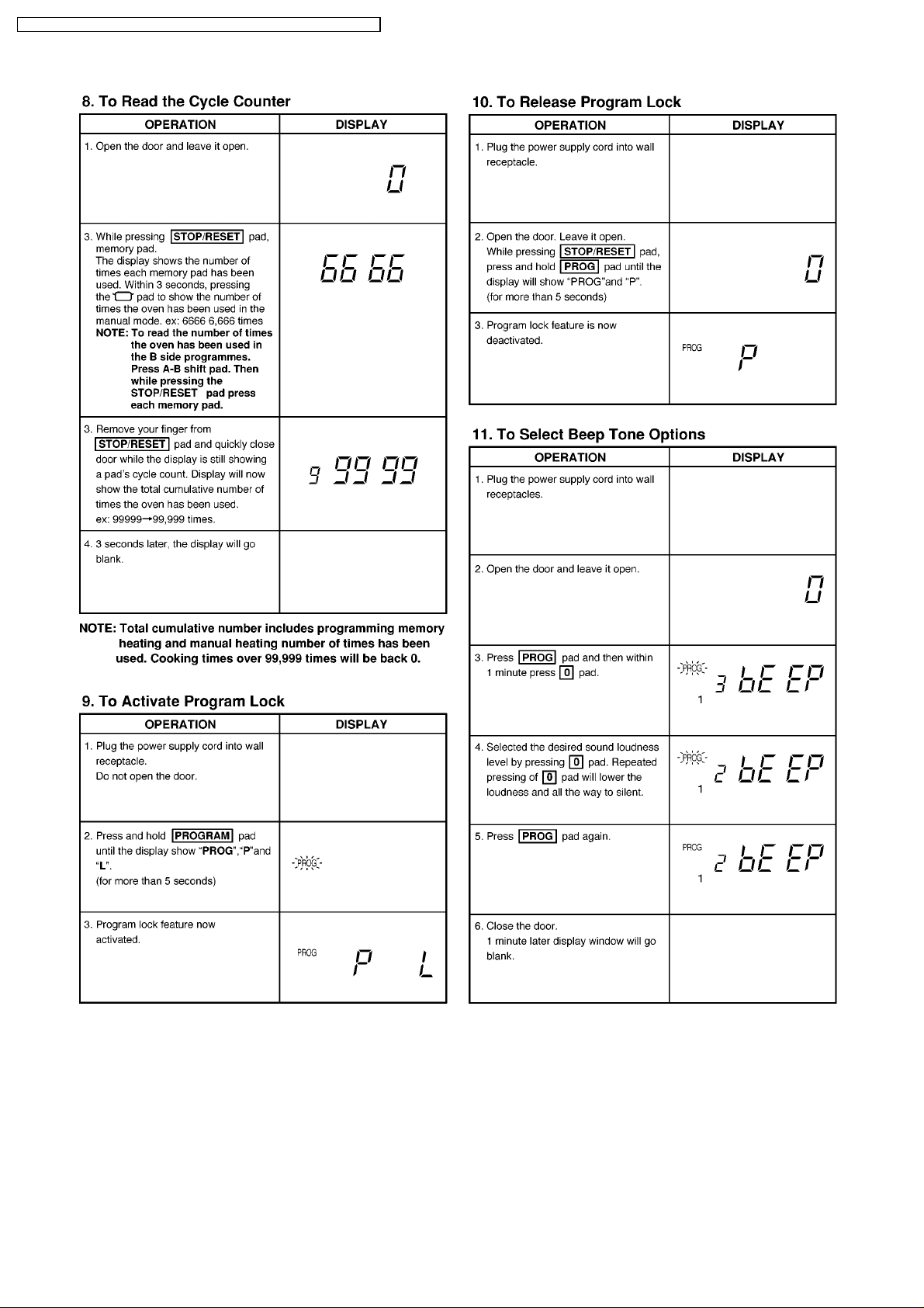
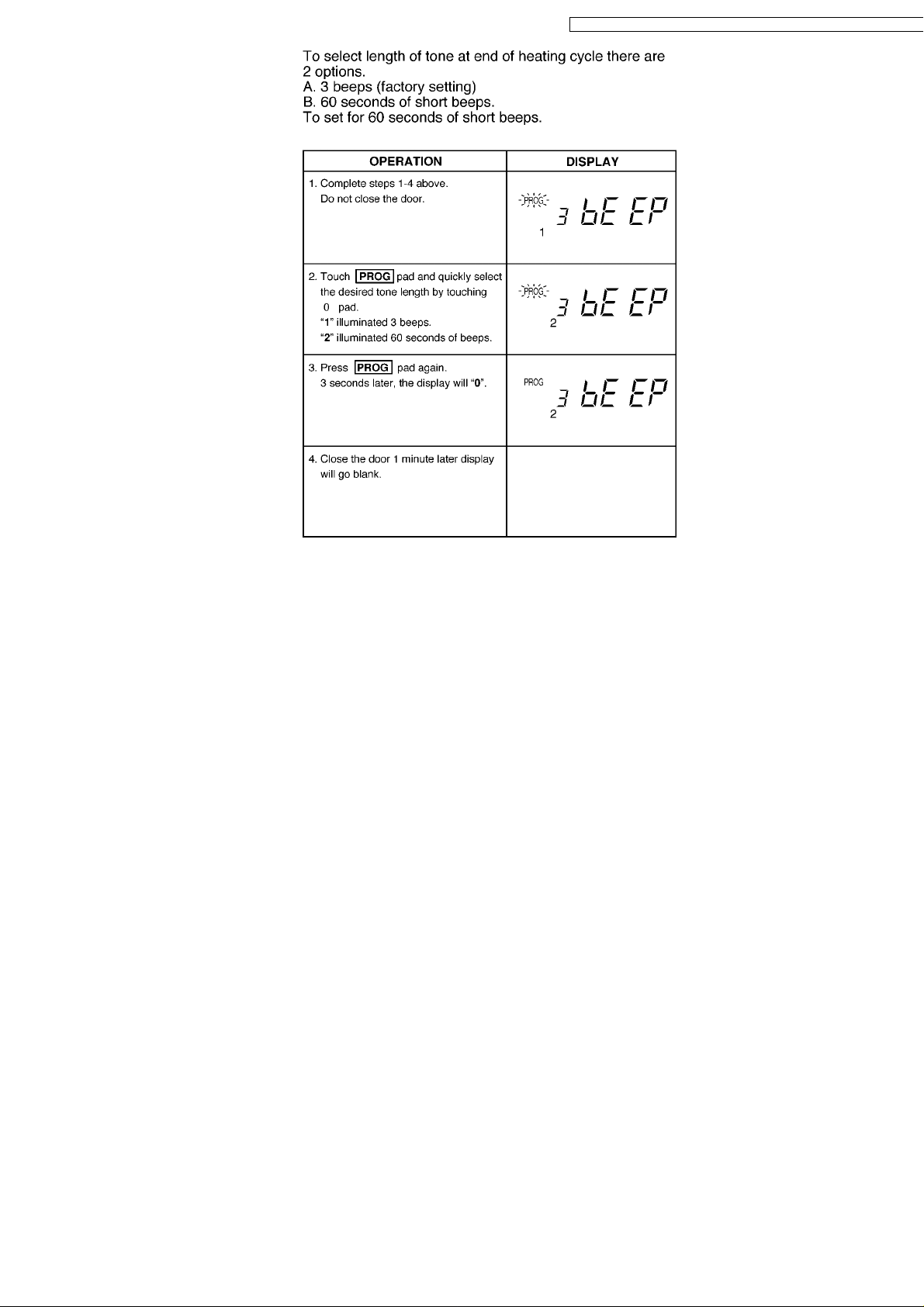
2 OPERATION PROCEDURE
NE-1257R/NE-1257CR / NE-1757R/NE-1757CR / NE-2157R/NE-2157CR / NE-1258
5
Page 6
NE-1257R/NE-1257CR / NE-1757R/NE-1757CR / NE-2157R/NE-2157CR / NE-1258R
6
Page 7
NE-1257R/NE-1257CR / NE-1757R/NE-1757CR / NE-2157R/NE-2157CR / NE-1258
7
Page 8
NE-1257R/NE-1257CR / NE-1757R/NE-1757CR / NE-2157R/NE-2157CR / NE-1258R
8
Page 9
NE-1257R/NE-1257CR / NE-1757R/NE-1757CR / NE-2157R/NE-2157CR / NE-1258
9
Page 10
NE-1257R/NE-1257CR / NE-1757R/NE-1757CR / NE-2157R/NE-2157CR / NE-1258R
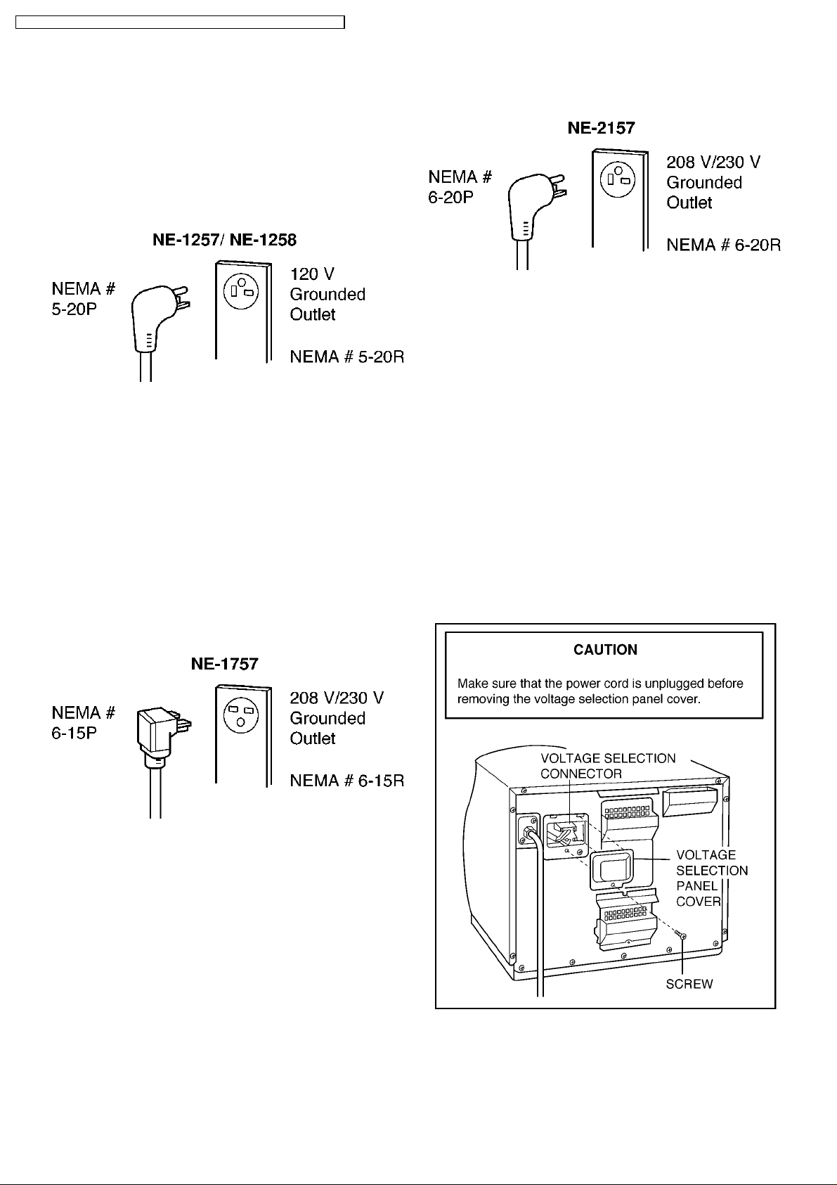
3 WIRING REQUIREMENTS AND POWER SOURCE
VOLTAGE SELECTION
Wiring Requirements
No other appliance should share the circuit with the microwave
oven. If it does, the branch circuit fuse may overload and either
cause the oven to heat slower than expected or blow the fuse.
1. For Mode NE-1257
The oven must be on a SEPARATE, 20 Amp, 60 Hz-120V
GROUNDED CIRCUIT.
2. For Model NE-1757
a. This oven must be on a separate, 60 Hz GROUNDED
CIRCUIT-minimum 15 amps.
b. The microwave ovens are built to operate on 2 different
voltages (230 V or 208 V). Be sure that the voltage
selector connector (on the back of the oven) is set for
your power supply. Connecting oven to 230 volt line with
208 voltage setting is dangerous and may result in
overheating of the electrical components thus
shortening their life expectancy or possibly causing a
fire or other accident. Connecting oven to 230 volt line
with 208 voltage will lower the power output of the oven,
resulting in slower heating of the food. Panasonic is
NOT responsible for damage resulting from the use of
the oven with other than specified voltage.
the oven with other than specified voltage.
Power Source Voltage Selection
The microwave oven Models NE-1757 & NE-2157 are factory
set for 208 V operation. For 230 V operation, the following
selection MUST be made.
(Step 1) Unscrew the voltage selection panel cover which is
located on the back of the oven. Do not remove any other parts
from the oven.
(Step 2) Remove the while connector and plug the black
connector into the socket.
(Step 3) Store the unused white connector in the rectangular
opening.
(Step 4) Reattach the voltage adjustment panel cover to the
cabinet.
For 230 V - Use black connector plug.
For 208 V - Use white connector plug.
To go from 230 V to 208 V circuit follow steps 1-4 above,
except at step 2, plug the white connector plug into the socket
and store the black plug in the rectangular opening.
3. For Model NE-2157
a. This oven must be on a separate, 60 Hz GROUNDED
CIRCUIT-minimum 20 amps.
b. The microwave ovens are built to operate on 2 different
voltages (230 V or 208 V). Be sure that the voltage
selector connector (on the back of the oven) is set for
your power supply. Connecting oven to 230 volt line with
208 voltage setting is dangerous and may result in
overheating of the electrical components thus
shortening their life expectancy or possibly causing a
fire or other accident. Connecting oven to 230 volt line
with 208 voltage will lower the power output of the oven,
resulting in slower heating of the food. Panasonic is
NOT responsible for damage resulting from the use of
10
Page 11
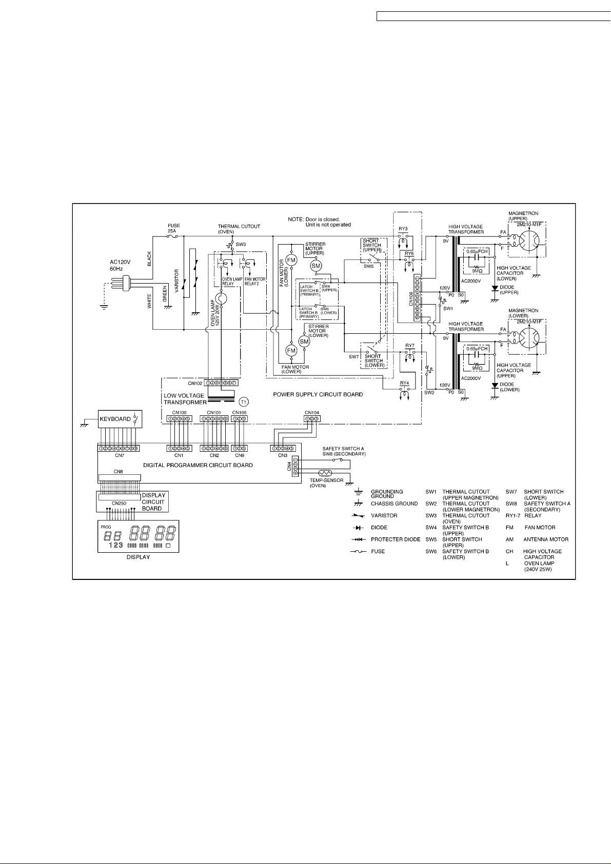
NE-1257R/NE-1257CR / NE-1757R/NE-1757CR / NE-2157R/NE-2157CR / NE-1258
4 SCHEMATIC DIAGRAM (NE-1257R, NE-1258R)
11
Page 12
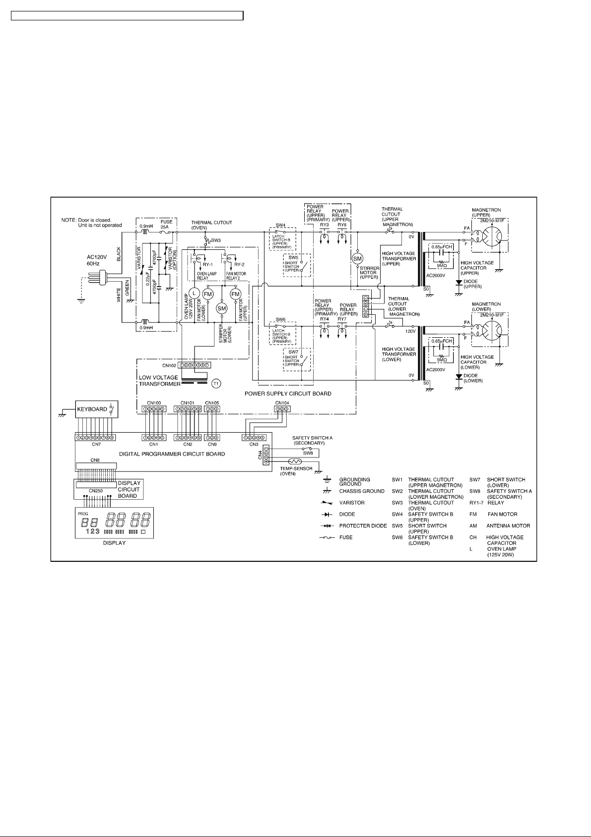
NE-1257R/NE-1257CR / NE-1757R/NE-1757CR / NE-2157R/NE-2157CR / NE-1258R
5 SCHEMATIC DIAGRAM (NE-1257CR)
12
Page 13
NE-1257R/NE-1257CR / NE-1757R/NE-1757CR / NE-2157R/NE-2157CR / NE-1258
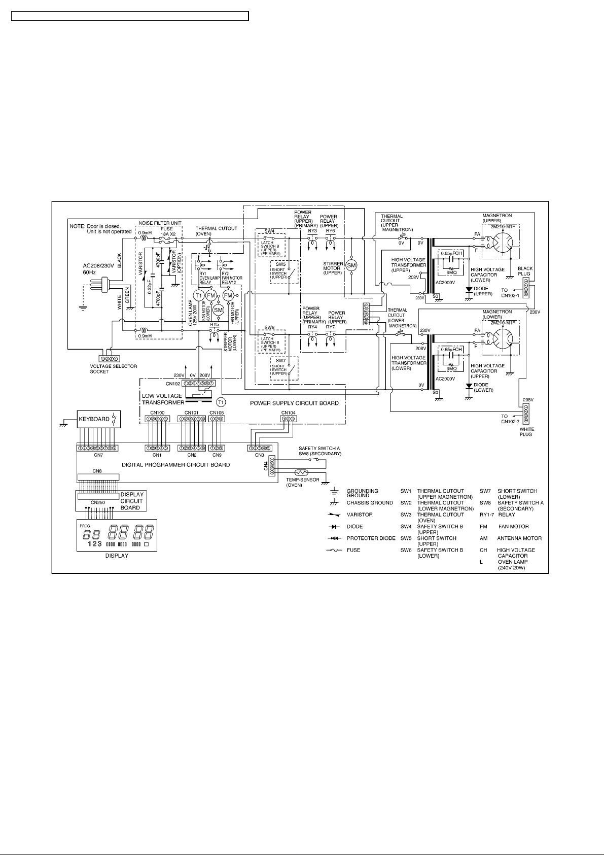
6 SCHEMATIC DIAGRAM (NE-1757R)
13
Page 14
NE-1257R/NE-1257CR / NE-1757R/NE-1757CR / NE-2157R/NE-2157CR / NE-1258R
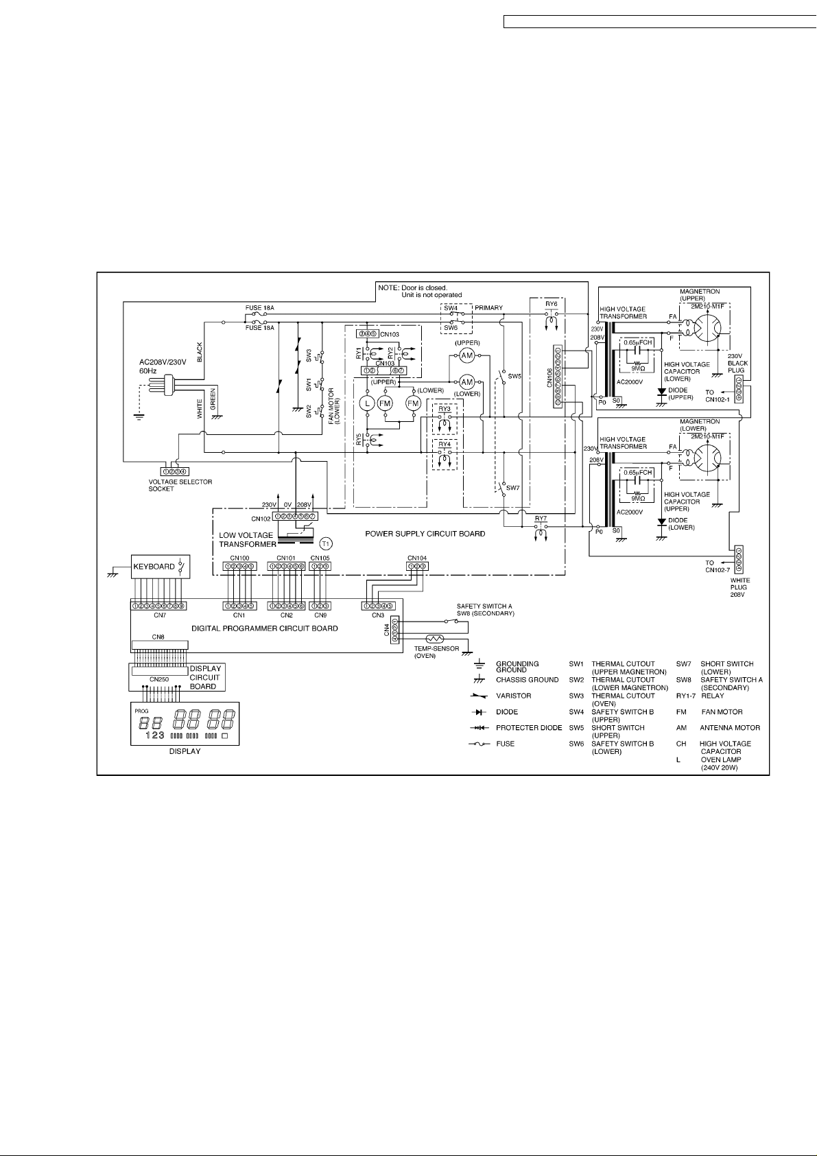
7 SCHEMATIC DIAGRAM (NE-1757CR)
14
Page 15
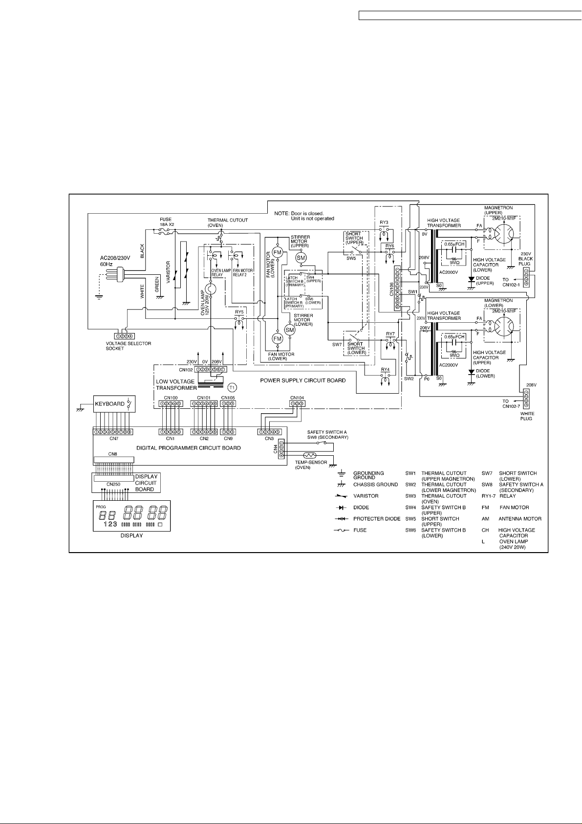
NE-1257R/NE-1257CR / NE-1757R/NE-1757CR / NE-2157R/NE-2157CR / NE-1258
8 SCHEMATIC DIAGRAM (NE-2157R)
15
Page 16

NE-1257R/NE-1257CR / NE-1757R/NE-1757CR / NE-2157R/NE-2157CR / NE-1258R
9 SCHEMATIC DIAGRAM (NE-2157CR)
16
Page 17

NE-1257R/NE-1257CR / NE-1757R/NE-1757CR / NE-2157R/NE-2157CR / NE-1258
10 WIRING DIAGRAM (NE-1257R, NE-1258R)
NOTE: When replacing, check the lead wire color as shown.
17
Page 18

NE-1257R/NE-1257CR / NE-1757R/NE-1757CR / NE-2157R/NE-2157CR / NE-1258R
11 WIRING DIAGRAM (NE-1257CR)
NOTE: When replacing, check the lead wire color as shown.
18
Page 19

12 WIRING DIAGRAM (NE-1757R)
NOTE: When replacing, check the lead wire color as shown.
NE-1257R/NE-1257CR / NE-1757R/NE-1757CR / NE-2157R/NE-2157CR / NE-1258
19
Page 20

NE-1257R/NE-1257CR / NE-1757R/NE-1757CR / NE-2157R/NE-2157CR / NE-1258R
13 WIRING DIAGRAM (NE-1757CR)
NOTE: When replacing, check the lead wire color as shown.
20
Page 21

14 WIRING DIAGRAM (NE-2157R)
NOTE: When replacing, check the lead wire color as shown.
NE-1257R/NE-1257CR / NE-1757R/NE-1757CR / NE-2157R/NE-2157CR / NE-1258
21
Page 22

NE-1257R/NE-1257CR / NE-1757R/NE-1757CR / NE-2157R/NE-2157CR / NE-1258R
15 WIRING DIAGRAM (NE-2157CR)
NOTE: When replacing, check the lead wire color as shown.
22
Page 23

NE-1257R/NE-1257CR / NE-1757R/NE-1757CR / NE-2157R/NE-2157CR / NE-1258
16 DESCRIPTION OF OPERATING SEQUENCE
Variable power cooking control
The coil of power relay A and B are energized intermittently by
the digital programmer circuit, when the oven is set to MEDIUM
or DEFROST power position. The digital programmer circuit
controls the ON-OFF time of the power relay A and B contacts
in order to vary the output power of the microwave oven. One
complete ON and OFF cycle of the power relay is 44 seconds.
The relation between indications on the control panel and the
output power of the microwave oven is as shown in Figure.
23
Page 24

NE-1257R/NE-1257CR / NE-1757R/NE-1757CR / NE-2157R/NE-2157CR / NE-1258R
17 CAUTIONS TO BE OBSERVED WHEN
TROUBLESHOOTING
Unlike many other appliances, the microwave oven is highvoltage, high-current equipment. Though it is free from danger
in ordinary use, extreme care should be taken during repair.
17.1. Check the grounding
Do not operate on a 2-wire extension cord. The microwave
oven is designed to be used in a completely grounded
condition. It is imperative, therefore, to make sure it is properly
grounded before beginning repair work.
17.2. If the door lock, the door
switch, the door seal or the
door develops a malfunction,
be sure not to operate the
oven until complete repairs
are made.
If the oven is operated with any of these parts in imperfect
condition, hazardous microwave leakage might occur.
17.3. Warning about the electric
charge in the high voltage
capacitor
For about 30 seconds after the oven is turned off, an electric
charge remains in the high voltage capacitor. When replacing
or checking parts, remove the power plug from the outlet, wait
30 seconds and short the terminal of the high voltage capacitor
(terminal of lead wire from diode) to chassis ground with an
insulated jumper lead wire or an insulated handle screwdriver
discharge.
17.4. When parts must be replaced,
always remove the power plug
from the outlet, and discharge
the high voltage capacitor.
24
Page 25

17.5. Confirm after repair
1. After repair or replacement of parts, make sure that the
screws of the oven, etc. are neither loose nor missing.
Microwave might leak if screws are not properly tightened.
2. Make sure that all electrical connections are tight before
inserting the plug into the wall outlet.
17.6. Avoid inserting nails, wire, etc.
through holes in unit during
operation.
Never insert a wire, nail or any other metal object through the
lamp holes on the cavity or any other holes or gaps, because
such objects may work as an antenna and cause microwave
leakage.
NE-1257R/NE-1257CR / NE-1757R/NE-1757CR / NE-2157R/NE-2157CR / NE-1258
25
Page 26

NE-1257R/NE-1257CR / NE-1757R/NE-1757CR / NE-2157R/NE-2157CR / NE-1258R
18 DISASSEM BLY AND PARTS REPLACEMENT
PROCEDURE
18.1. Replacement of magnetrons
(Upper and Lower)
Upper magnetron
1. Discharge electric charge remaining on the high voltage
capacitors.
2. Remove the entire rear panel by removing screws as
shown.
3. Disconnect all lead wires from magnetron and thermal
cutout.
4. Remove the 4 screws holding magnetron.
5. Remove 2 screws holding thermal cutout.
6. Remove the mounting bracket from magnetron and install it
on the new magnetron.
Lower magnetron
1. Discharge electric charge remaining on the high voltage
capacitors.
2. Remove the entire rear panel by removing screws as
shown.
3. Carefully place the unit on its left side (H. V. Capacitor
side).
4. Remove the cover by removing 2 screws.
5. Remove the 4 screws holding magnetron by inserting
screwdriver through the 4 openings on bottom plate.
6. Remove 2 screws holding thermal cutout.
7. Remove the mounting bracket from magnetron and install it
on the new magnetron.
NOTE: To prevent microwave leakage, tighten mounting
screws properly makin g sure there is no gap between the
waveguide and the magnetron.
26
Page 27

Removal of Positive Lock connector
The positive lock connector is a specially designed loose free
connector and you will find this connector in many lead wire
connections. To remove this connector, pull the lead wire by
pressing an extruded lever in the center of receptacle terminal
as shown.
NE-1257R/NE-1257CR / NE-1757R/NE-1757CR / NE-2157R/NE-2157CR / NE-1258
18.2. Replacement of power supply
circuit board
NOTE: Be sure to ground any static electric charge built up
on your body, before handling the power supply P. C. B.
and D. P. C..
1. Disconnect all lead wires from power supply circuit board.
2. Remove the power supply P. C. B. together with its
mounting bracket by first removing the 2 bracket holding
screws.
3. The power supply P. C. B. can be separated from mounting
bracket by removing the 2 L. V. T. holding screws and
unfastening the plastic clips.
18.3. Replacement of digital
programmer circuit board
1. Remove grounding screw for membrane switch and D. P.
C. ground.
2. Remove 3 screws holding control panel assembly to detach
it from main unit then remove connectors.
3. Remove 2 screws holding the D. P. C. board and while
pushing back on 2 plastic holding clips, remove the board.
NOTE: Please use care in handling the power supply P. C.
B. and D. P. C. board to avoid damage.
27
Page 28

NE-1257R/NE-1257CR / NE-1757R/NE-1757CR / NE-2157R/NE-2157CR / NE-1258R
18.4. Replacement of upper antenna
1. Remove ceiling plate by gently moving the left and right
tabs inward while pulling the plate down and outward.
2. Using a small flat screwdriver or the like, remove two plastic
clips located on the antenna ring. Nest turn the antenna ring
approx. 1/8 turn clockwise to unhook the tabs and pull off.
18.5. Replacement of floor shelf and
lower antenna
1. To remove the floor shelf, insert a screwdriver through the
small opening on the left side of the oven cavity and
carefully lift the floor shelf.
2. For removal of lower antenna, use the same procedure as
upper antenna.
18.6. Replacement of temperature
sensor (Thermal protector)
1. Cut 2 lead wires at the top of sensor terminals.
28
Page 29

2. Remove 2 screws holding temp sensor and replace with
new one.
3. Solder the lead wires securely to the sensor terminals.
18.7. Disassembly of door assembly
1. Remove each 2 bolts holding upper and lower hinges.
2. Open the door and while pulling the door outward, work
upper and lower hinges out through the holes of the front
surface of oven.
3. Remove door C (check cover) from door E by carefully
pulling outward starting from the upper right hand corner.
4. Remove 2 screws holding door handle and separate door A
from door E by carefully freeing catch hooks.
5. Remove door key, door key lever, door key spring and
handle pins from door E.
6. Assemble the door by taking the above steps in a reverse
order.
Replacement
1. When mounting the door to the oven be sure to adjust the
door parallel to the bottom line of the oven face plate by
moving the upper hinge and lower hinge in the direction
necessary for proper alignment.
2. Adjust so that the door has no play between the inner door
surface and oven front surface. If the door assembly is not
mounted properly, microwave may leak from the clearance
between the door and the oven.
NOTE: Please refer to MEASURENMENT AND
ADJUSTMENT.
NE-1257R/NE-1257CR / NE-1757R/NE-1757CR / NE-2157R/NE-2157CR / NE-1258
29
Page 30

NE-1257R/NE-1257CR / NE-1757R/NE-1757CR / NE-2157R/NE-2157CR / NE-1258R
19 COMPONENT TEST PROCEDU RE
19.1. High voltage transformer
1. Remove connections from the transformer terminals and
check continuity.
2. Normal (cold) resistance readings should be as follows:
Secondary winding Approx. 80Ω—120Ω
Filament winding Approx. 0Ω
Primary winding Approx. 0Ω—3Ω
19.2. High voltage capacitor
1. Check continuity of capacitor with meter on highest OHM
scale.
2. A normal capacitor will show continuity for a short time, and
then indicate 9MΩ once the capacitor is charged.
3. A shorted capacitor will show continuous continuity.
4. An open capacitor will show constant 9MΩ.
5. Resistance between each terminal and chassis should be
infinite.
19.3. Magnetron
Continuity checks can only indicate an open filament or a
shorted magnetron. To diagnose for an open filament or
shorted magnetron.
1. Isolate magnetron from the circuit by disconnecting the
leads.
2. A continuity check across magnetron filament terminals
should indicate one ohm or less.
3. A continuity check between each filament terminal and
magnetron case should read open.
19.4. Diode
1. Isolate the diode from the circuit by disconnecting the leads.
2. With the ohmmeter set on the highest resistance scale,
measure the resistance across the diode terminals.
Reverse the meter leads and again observe the resistance
reading. Meter with 6V, 9V or higher voltage batteries
should be used to check the front-to-back resistance of the
diode, otherwise an infinite resistance may be read in both
directions.
A normal diode's resistance will be infinite in one direction
and several hundred kΩ in the other direction.
19.5. Membrane key board
(Membrane switch assembly)
Check continuity between switch terminals, by tapping an
appropriate pad on the key board. The contacts assignment of
the respective pads on the key board is as shown in digital
programmer circuit.
19.6. Protector diode
1. Isolate the protector diode assembly from the circuit by
disconnecting its leads.
2. With the ohmmeter set on the highest resistance scale,
measure the resistance across the protector diode
terminals.
Reverse the meter leads and again observe the resistance
reading. A normal protector diode's resistance will be
infinite in both directions. It is faulty if it shows continuity in
30
Page 31

one or both directions.
19.7. Temp sensor (Thermal
protector)
A temp sensor is mount ed on exhaust guide. Its purpose is to
automatically shut off the oven in case the cavity overheats for
any reason.
The thermal protector will operate at 257°F (125°C).
The device is connected to the DPC on touch control models.
When the thermal protector exceeds its temperature it will turn
off the power to oven cavity and display will go to reset mode.
The cooking program can be reset after cool-down.
THERMISTOR RESISTANCE VALUE
30K—120K at 10°C—30°C (50°F—86°F)
NE-1257R/NE-1257CR / NE-1757R/NE-1757CR / NE-2157R/NE-2157CR / NE-1258
31
Page 32

NE-1257R/NE-1257CR / NE-1757R/NE-1757CR / NE-2157R/NE-2157CR / NE-1258R
20 MEASUREMENTS AND ADJUSTMENTS
water using the thermometer and record the beaker's
temperature (recorded as T1)
2. Place the beaker on the center of ceramic shelf.
3. Set the one to High power and heat it for exactly one
minute.
4. Stir the water again and read the temperature of the beaker
(recorded as T2). The normal temperature rise (T2-T1) at
High power output for each model is as shown in table.
20.1. Installation of Safety switch A,
Safety switch B and Short
switch
1. When mounting Safety switch A, Safety switch B and short
switch to door hook assembly, mount the Safety switch A,
Safety switch B and the short switch to the door hook
assembly as shown. (in Figure).
NOTE: No specific adjustment during installation of
Safety switch A, Safety switch B and short switch to the
door hook is necessary.
2. When mounting the door hook assembly to the oven
assembly, adjust the door hook assembly by moving it in
the direction of arrow in (Figure) so that the oven door will
not have any play in it. Check for play in the door by pulling
the door assembly. Make sure that the latch keys move
smoothly after adjustment it completed. Completely tighten
the screws holding the door hook assembly to the oven
assembly.
3. Reconnect the short switch, safety switches A&Band
check the continuity of t monitor circuit and all latch
switches again.
20.2. Measurement of microwave
output
The power output of the magnetron can be determined by
performing IEC standard test procedures. However, due to the
complexity of IEC test procedures, it is recommended to test
the magnetron using the simple method outlined below.
Necessary Equipment:
*1 liter beaker
*Glass thermometer (Celsius scale)
*Wrist watch or stopwatch
NOTE: Check the line voltage under load. Low voltage will
lower the magnetron output. Take the temperature
readings and heating time as accurately as possible.
1. Fill the beaker with exactly one liter of tap water. Stir the
32
Page 33

NE-1257R/NE-1257CR / NE-1757R/NE-1757CR / NE-2157R/NE-2157CR / NE-1258
21 PROCEDURE FOR MEASURING MICROWAVE ENERGY
LEAKAGE
periphery, the door viewing window, the exhaust opening
and air inlet openings.
21.2. Record keeping and
notification after measurement
1. After any adjustment or repair to a microwave oven, a
leakage reading must be taken. Record this leakage
reading on the repair ticket even if it is zero.
A copy of this repair ticket and the microwave leakage
reading should be kept by repair facility.
2. Should the radiation leakage be more than 2 mW/cm2 (1
NOTE: The U. S. Government standard is 5 mW/cm2while
in the customer's home. 2 mW/cm
voluntary standard. (1 mW/cm
2
stated here is our own
2
for Canada)
21.1. Equipment
Note before measuring.
1. Do not exceed meter full scale deflection. Leakage monitor
should initially be set to the highest scale.
2. To prevent false readings the test probe should be held by
the grip portion of the handle only and moved along the
shaded area shown in Figure no faster than 1 inch/sec (2.5
cm/sec).
3. Leakage with the outer panel removed — less than 5
mW/cm
4. Leakage for a fully assembled oven with door normally
closed — less than 2 mW/cm
5. Leakage for a fully assembled oven [Before the latch switch
(primary) is interrupted] while pulling the door — less than
2 mW/cm
1. Pour 275± 15cc (9ozs ± 1/2oz) of 20 ± 5°C (68± 9°F) water
in a beaker which has graduations to 600cc, and place in
the center of the oven.
2. Set the radiation monitor to 2450MHz and use it following
the manufacture 's recommended test procedure to assure
correct results.
3. When measuring the leakage, always use the 2 inch (5 cm)
spacer supplied with the probe.
4. Tap the start pad or set the timer and with the magnetron
oscillating, measure the leakage by holding the probe
perpendicular to the surface being measured.
1. Measurement with the outer pane removed.
Whenever you replace the magnetron, measure for
radiation leakage before the outer panel is installed and
after all necessary components are replaced or adjusted.
Special care should be taken when measuring around the
magnetron.
2
.
2
(1 mW/cm2for Canada).
2
.
mW/cm2 for Canada) after determining that all parts are in
good condition, functioning properly, and genuine
replacement parts as listed in this manual have been used,
immediately notify PHCC, PSC or PCI.
21.3. At least once a year, have the
radiation monitor checked for
calibration by its
manufacturer.
2. Measurements with a fully assembled oven.
After all components, including outer panel are fully
assembled, measure for radiation leakage around the door
33
Page 34

NE-1257R/NE-1257CR / NE-1757R/NE-1757CR / NE-2157R/NE-2157CR / NE-1258R
34
Page 35

22 TROUBLESHOOTING GUIDE
NE-1257R/NE-1257CR / NE-1757R/NE-1757CR / NE-2157R/NE-2157CR / NE-1258
35
Page 36

NE-1257R/NE-1257CR / NE-1757R/NE-1757CR / NE-2157R/NE-2157CR / NE-1258R
23 EXPLODE D VIEW AND PARTS LIST
36
Page 37

NE-1257R/NE-1257CR / NE-1757R/NE-1757CR / NE-2157R/NE-2157CR / NE-1258
24 PARTS LIST
NOTE: When ordering replacement part(s), please use part number(s) shown in this parts list.
Important safety notice:
Components identified
When replacing any of these components, use only manufacture's specified parts.
by mark have special characteristics important for safety.
Ref.
No.
1 ANE00068U0CP WARNING LABEL 1 NE-1257CR NE-1757CR NE-2157CR
1 A00064000AP WARNING LABEL 1 NE-1257R NE-1258R NE-1757R NE-2157R
2 A00333960AP FUSE LABEL 1
3 A0056-3500 HIGH VOLTAGE LABEL 1
4 ANE0072L20CP CAUTION LABEL 1 NE-1257CR NE-1757CR NE-2157CR
4 ANE0072L20AP CAUTION LABEL 1 NE-1257R NE-1258R NE-1757R NE-2157R
5 ANE010T8U0AP SHELF 1
6 ANE0150110AG CAUTION LABEL 1 NE-1257R NE-1258R NE-1757R NE-2157R
7 ANE01728U0CP CAUTION LABEL 1
8 ANE05108V0CP CAUTION LABEL 1 NE-1757CR NE-2157CR
8 ANE05108V0AP CAUTION LABEL 1 NE-1757R NE-2157R
9 A05243960AP NAME LABEL 1 NE-1257R
9 A05243990AP NAME LABEL 1 NE-1258R
9 A05243970AP NAME LABEL 1 NE-1757R
9 A05243980AP NAME LABEL 1 NE-2157R
9 A05243960CP NAME LABEL 1 NE-1257CR
9 A05243970CP NAME LABEL 1 NE-1757CR
9 A05243980CP NAME LABEL 1 NE-2157CR
10 ANE0901000CD CUSHION RUBBER A 1
11 ANE000Z000AD CUSHION RUBBER A 5 NE-1257R NE-1757R
11 ANE000Z000AD CUSHION RUBBER A 5 NE-1257R NE-1757R
12 ANE0911000MG CUSHION RUBBER B 1
13 ANE000Z000AA CUSHION RUBBER C 10
13 ANE000Z000AA CUSHION RUBBER C 10
13 ANE000Z000AA CUSHION RUBBER C 10
13 ANE000Z000AA CUSHION RUBBER C 10
13 ANE000Z000AA CUSHION RUBBER C 10
13 ANE000Z000AA CUSHION RUBBER C 10
13 ANE000Z000AA CUSHION RUBBER C 10
13 ANE000Z000AA CUSHION RUBBER C 10
13 ANE000Z000AA CUSHION RUBBER C 10
14 ANE000Z000AD CUSHION RUBBER C 4 NE-1257CR NE-1757CR NE-2157CR
14 ANE000Z000AD CUSHION RUBBER C 5 NE-1258R NE-2157R
15 ANE000Z000AB CUSHION RUBBER C 1
16 ANE0962000AP CUSHION RUBBER D 1
17 ANE0962000AV CUSHION RUBBER D 1
18 A100A-3280 BASE 1
19 A100Q-3280 BACK PANEL 1
20 A1007-3280 FOOT 4
20 A1007-3280 FOOT 4
20 A1007-3280 FOOT 4
20 A1007-3280 FOOT 4
21 A1008-3280 RUBBER FOOT 4
21 A1008-3280 RUBBER FOOT 4
21 A1008-3280 RUBBER FOOT 4
21 A1008-3280 RUBBER FOOT 4
22 ANE10098U0AP CABINET BODY 1
23 ANE10268U0AP LAMP COVER 1
24 ANE10288U0AP ANTENNA MOTOR COVER 1
25 ANE10498U0AP CUSHION RUBBER 1
26 NE11268U0AP BASE BRACKET 1
27 ANE1062-8U0 CUSHION RUBBER B 2
27 ANE1062-8U0 CUSHION RUBBER B 2
28 ANE11408A0AG STOPPER 1
29 ANE11548U0AP BACK PANEL COVER 1
30 ANE11668U0AP BASE METAL 1
31 ANE11748U0AP SPACER 1
32 A200A-3280 OVEN 1
33 A2011-3470 CEILING PLATE 1
34 A202K-3850 ANTENNA 1 (UPPER)
35 A202V3310GP ANTENNA B 1 (LOWER) NE-1257R NE-1257CR NE-1757R NE-1757CR NE-
35 A202V-3850 ANTENNA B 1 NE-2157R NE-2157CR (LOWER)
36 ANE21208U0AP SPACER 1
Part No. Part Name & Description Pcs/
Set
Remarks
1258R
37
Page 38

NE-1257R/NE-1257CR / NE-1757R/NE-1757CR / NE-2157R/NE-2157CR / NE-1258R
Ref.
No.
37 A8251-3180 SPACER 1
38 A3020-3850 DOOR HOOK A 1
39 A3136-3470 HOOK SPACER A 1
40 A3137-3850 HOOK SPACER B 1
41 A3138-3470 HOOK SPACER C 1
42 A31863960CP DOOR PANEL 1 NE-1257CR
42 A31863960AP DOOR PANEL 1 NE-1257R
42 A31863990AP DOOR PANEL 1 NE-1258R
42 A31863970CP DOOR PANEL 1 NE-1757CR
42 A31863970AP DOOR PANEL 1 NE-1757R
42 A31863980AP DOOR PANEL 1 NE-2157R
42 A31863980CP DOOR PANEL 1 NE-2157CR
43 ANE32398U0AP SPRING 1
44 ANE32628U0AP SPRING 3
44 ANE32628U0AP SPRING 3
45 A400A3650AP FAN MOTOR 2 NE-1257CR NE-1257R NE-1258R (50W)
45 A400A3660AP FAN MOTOR 2 NE-1757CR NE-1757R (54W)
45 A400A3780AP FAN MOTOR 2 NE-2157R NE-2157CR (51W)
46 A400B-3280 AIR FILTER FLAME 1
47 A4024-3180 EXHAUST GUIDE A 1
48 ANE40258U0AP AIR GUIDE A 1
49 ANE40268U0AP AIR GUIDE B 1
50 A4091-3280 SCREW 1 FOR AIR FILTER FLAME
51 ANE41038U0AP AIR GUIDE CUSHION B 1
52 ANE50328U0AP MAGNETRON BRACKET 2
52 ANE50328U0AP MAGNETRON BRACKET 2
53 A50493650CP FIRE BARRIER 1 NE-1257CR NE-1757CR
53 A50493780CP FIRE BARRIER 1 NE-2157CR
54 A603L3960AP D.P.CIRCUIT (U) 1 NE-1257CR NE-1257R NE-1258R RTL (W/COMPONENT)
54 A603L3970AP D.P.CIRCUIT (U) 1 NE-1757CR NE-1757R RTL (W/COMPONENT)
54 A603L3980AP D.P.CIRCUIT (U) 1 NE-2157R NE-2157CR RTL (W/COMPONENT)
55 ANE6030540AP INCANDESCENT LAMP 1 NE-1257CR NE-1257R NE-1258R (125V 20W)
55 A60304080BP INCANDESCENT LAMP 1 NE-1757CR NE-1757R NE-2157R NE-2157CR (240V 20W)
56 ANE60408U0AP OVEN LAMP SHEET 2 NE-1257CR NE-1257R NE-1258R NE-1757CR NE-1757R
56 A60403780AP OVEN LAMP SHEET 2 NE-2157R NE-2157CR
57 ANE61458U0AP THERMAL CUTOUT 2
57 ANE61458U0AP THERMAL CUTOUT 2
57 ANE61458U0AP THERMAL CUTOUT 2
58 A605S3650CP PC BOARD H (U) 1 NE-1257CR
58 A605S3660CP PC BOARD H (U) 1 NE-1757CR NE-2157CR
59 ANE60708U0BP INSULATION SHEET A 1
60 A60713310BP INSULATION SHEET B 1
61 A60903650AP H.V.CAPACITOR 2 NE-1257CR NE-1257R NE-1258R
61 A60903660AP H.V.CAPACITOR 2 NE-1757CR NE-1757R
61 A60903780AP H.V.CAPACITOR 2 NE-2157R NE-2157CR
62 A6070-3280 INSULATION SHEET A 2
63 ANE6142-F60 MICROSWITCH 2 (V-15G-3C26)PRIMARY LATCH SWITCH
64 ANE61424L0AG MICROSWITCH 1 (V-16G-3C26)SECONDARY LATCH SWITCH
65 A6144-3280 ANTENNA MOTOR 1 NE-1257CR NE-1257R NE-1258R NE-1757CR NE-1757R
65 A61443030GP ANTENNA MOTOR 1 NE-2157R NE-2157CR (2.5W)
68 A61443660AP ANTENNA MOTOR 1 NE-1757CR NE-1757R NE-2157R NE-2157CR (2.5W)
68 A61446030AP ANTENNA MOTOR 1 NE-1257CR NE-1257R NE-1258R (2.5W)
69 A65943030GP MOTOR COVER 1
70 ANE61458U0AP THERMAL CUTOUT 1 NE-1257R NE-1757R
71 ANE61454L0AG THERMAL CUTOUT 1 NE-1257CR NE-1757CR
71 A61454050AP THERMAL CUTOUT 1 NE-2157R NE-2157CR
72 A61524210AA SOCKET 1
73 A6170-3280 INSULATION SHEET C 1 NE-1257CR NE-1757CR NE-2157CR
74 ANE61784L0AG MICRO SWITCH 2 (V-16G-2C25) SHORT SWITCH
75 ANE61888U0AP CAPACITOR BRACKET 2
76 A62023960AP DIODE SI 2 NE-1257CR NE-1257R NE-1258R NE-1757CR NE-1757R
76 A62023880AP DIODE SI 2 NE-2157R NE-2157CR
77 A621B3650AP H.V.TRANSFORMER 2 NE-1257CR NE-1257R NE-1258R
77 A621B3660AP H V.TRANSFORMER 2 NE-1757CR NE-1757R
77 A621B3780AP H.V.TRANSFORMER 2 NE-2157R NE-2157CR
78 ANE62298U0AP MOUNTING BRACKET 1
79 ANE6230P90AP FUSE 1 NE-1257CR NE-1257R NE-1258R (25A)
79 A62303970AP FUSE 2 NE-1757CR NE-1757R NE-2157R NE-2157CR (18A)
80 A62314000AP FUSE HOLDER 1 NE-1257R NE-1258R
80 A62314000AP FUSE HOLDER 2 NE-1757R NE-2157R
81 ANE6238X20AP SPACER 1
82 ANE64086Q0AP WASHER 1
Part No. Part Name & Description Pcs/
Set
Remarks
(2.5W)
38
Page 39

NE-1257R/NE-1257CR / NE-1757R/NE-1757CR / NE-2157R/NE-2157CR / NE-1258
Ref.
No.
83 A6408-3280 WASHER 1
84 ANE65448U0AP SPACER A 1
85 A6585-3280 P.C.B.HOLDER 1
86 ANE66038U0AP OVEN LAMP BRACKET 1
87 ANE66268U0AP THERMAL CUTOUT MOUNT 1 NE-1257R NE-1258R NE-1757R
88 A6688-3180 P.C.B.COVER 1
89 A692M3650AP L.V.TRANSFORMER (U) 1 NE-1257CR NE-1257R NE-1258R
89 A692M3660AP L.V.TRANSFORMER (U) 1 NE-1757CR NE-1757R NE-2157R NE-2157CR
90 B900C3650CP AC CORD W/PLUG 1 NE-1257CR
90 B900C3650AP AC CORD W/PLUG 1 NE-1257R NE-1258R
90 B900C3660CP AC CORD W/PLUG 1 NE-1757CR
90 B900C3660AP AC CORD W/PLUG 1 NE-1757R
90 B900C3780AP ACCORD W/PLUG 1 NE-2157R
90 B900C3780CP AC CORD W/PLUG 1 NE-2157CR
91 ANE9027510RN CORD BUSHING 1
92 ANE9035P90AP CORD BRACKET 1
93 ANE90828U0AP CLIP(BLACK) 1
94 ANE91438U0AP CLIP(GLAY) 1 NE-1257CR NE-1257R NE-1258R
95 ANE91448U0AP BRACKET 1
96 ANE91628U0AP CLIP B 1
97 ANE91658V0AP CLIP 4
97 ANE91658V0AP CLIP 4
98 XTC4+10BC SCREW 4 (4X10) FOR CABINET BODY
98 XTC4+10BC SCREW 4 (4X10) FOR CABINET BODY
98 XTC4+10BC SCREW 4 (4X10) FOR CABINET BODY
99 XTC4+10FC SCREW 1 (4X10) FORLAMP COVER
100 XTC4+12BK SCREW (BLACK) 2 (4X12)FOR BASE
100 XTC4+12BK SCREW (BLACK) 2 (4X12)FOR BASE
101 XTEANE5+10B SCREW 4 (5X10)FOR H.V.TRANSFORMER
102 XTT4+8E SCREW 1 (4X8) FOR BACK PANEL COVER
103 XTWANE3+8EX SCREW 2 (3X8) FOR TEMP SENSOR
104 XTW3+8B SCREW 4 (3X8) FOR FOOT
105 XWC4BPN WASHER 2 FOR BACK PANEL COVER, LAMP COVER
105 XWC4BPN WASHER 2 FOR BACK PANEL COVER, LAMP COVER
106 XYD4+EE12F SCREW 11 (4X12)FOR DIODE, CAPACITOR BRACKET, AC CORD, MOTOR
106 XYD4+EE12F SCREW 11 (4X12)FOR DIODE, CAPACITOR BRACKET, AC CORD, MOTOR
106 XYD4+EE12F SCREW 11 (4X12)FOR DIODE, CAPACITOR BRACKET, AC CORD, MOTOR
106 XYD4+EE12F SCREW 11 (4X12)FOR DIODE, CAPACITOR BRACKET, AC CORD, MOTOR
106 XYD4+EE12F SCREW 11 (4X12)FOR DIODE, CAPACITOR BRACKET, AC CORD, MOTOR
106 XYD4+EE12F SCREW 11 (4X12)FOR DIODE, CAPACITOR BRACKET, AC CORD, MOTOR
106 XYD4+EE12F SCREW 11 (4X12)FOR DIODE, CAPACITOR BRACKET, AC CORD, MOTOR
106 XYD4+EE12F SCREW 11 (4X12)FOR DIODE, CAPACITOR BRACKET, AC CORD, MOTOR
106 XYD4+EE12F SCREW 11 (4X12)FOR DIODE, CAPACITOR BRACKET, AC CORD, MOTOR
106 XYD4+EE12F SCREW 11 (4X12)FOR DIODE, CAPACITOR BRACKET, AC CORD, MOTOR
106 XYD4+EE12F SCREW 11 (4X12)FOR DIODE, CAPACITOR BRACKET, AC CORD, MOTOR
106 XYD4+EE12F SCREW 11 (4X12)FOR DIODE, CAPACITOR BRACKET, AC CORD, MOTOR
107 XYEANE5+C16T SCREW 8 (5X16) FOR MAGNETRON
107 XYEANE5+C16T SCREW 8 (5X16) FOR MAGNETRON
107 XYEANE5+C16T SCREW 8 (5X16) FOR MAGNETRON
107 XYEANE5+C16T SCREW 8 (5X16) FOR MAGNETRON
108 XYEA4+C16TS SCREW 2
109 2M210-M1F1 MAGNETRON 2 NE-1257R NE-1258R NE-1757R
109 2M210-M1G MAGNETRON 2 NE-1257CR NE-1757CR
109 2M244-M1F1 MAGNETRON 2 NE-2157R NE-2157CR
109 2M244-M1G MAGNETRON 2 NE-2157R
110 A601L5150AP TEMP SENSOR 1
111 ANE0245X00AP DHHS LABEL 1 NE-1257R NE-1258R NE-1757R NE-2157R
111 A04115020CQ CSA LABEL 1 NE-1257CR NE-1757CR NE-2157CR
Part No. Part Name & Description Pcs/
Set
Remarks
COVER, BASE METAL ETC
COVER, BASE METAL ETC
COVER, BASE METAL ETC
COVER, BASE METAL ETC
COVER, BASE METAL ETC
COVER, BASE METAL ETC
COVER, BASE METAL ETC
COVER, BASE METAL ETC
COVER, BASE METAL ETC
COVER, BASE METAL ETC
COVER, BASE METAL ETC
COVER, BASE METAL ETC
39
Page 40

NE-1257R/NE-1257CR / NE-1757R/NE-1757CR / NE-2157R/NE-2157CR / NE-1258R
25 DOOR ASSEMBLY
Ref.
No.
D1 A3145-3500 DOOR SCREEN A 1
D2 ANE31468U0AP DOOR SCREEN B 1
D3 ANE30038U0AP DOOR FRAME(U) 1
D4 ANE301A8U0AP DOOR A 1
D5 A301H-3850 DOOR KEY LEVER B 1
D6 ANE301Q8U0AP DOOR E(U) 1
D7 A3018-3850 DOOR KEY A 1
D8 A3019-3850 DOOR KEY B 1
D9 ANE30218U0AP DOOR KEY SPRING 1
D10 ANE30562Q0AP HANDLE PIN 2
D10 ANE30562Q0AP HANDLE PIN 2
D11 A30703170GP HANDLE PEICE A 1
D12 ANE3081P60AP DOOR HINGE SPACER 1
D13 ANE30858U0AP DOOR C 1
D14 ANE30078U0AP HINGE 2
D14 ANE30078U0AP HINGE 2
D15 ANE31348U0AP HANDLE PEICE B 1
D16 XYEA4+C16TS SCREW 2 (4X16)
D16 XYEA4+C16TS SCREW 2 (4X16)
Part No. Part Name & Description Pcs/
Set
40
Remarks
Page 41

26 ESCUTCHEON BASE ASSEMBL Y
NE-1257R/NE-1257CR / NE-1757R/NE-1757CR / NE-2157R/NE-2157CR / NE-1258
Ref.
No.
E1 A8337-3280 ESCUTCHEON SHEET 1
E2 A603M3310GP PC BOARD B (U) 1
E3 A64793310QP MEMBRANE SWITCH 1
E4 A6590-3280 FLAT CABLE 1
E5 ANE80018U0AP ESCUTCHEON A 1
E6 ANE80028U0AP ESCUTCHEON B 1
E7 ANE80068U0AP ESCUTCHEON D 1
E8 A800L3310QP ESCUTCHEON BASE 1
Part No. Part Name & Description Pcs/
Set
Remarks
41
Page 42

NE-1257R/NE-1257CR / NE-1757R/NE-1757CR / NE-2157R/NE-2157CR / NE-1258R
27 PACKING AND ACCESSORIES
Ref.
No.
P1 A00033960CP INSTRUCTION BOOK 1 NE-1257CR NE-1757CR NE-2157CR
P1 A00033960AP INSTRUCTION BOOK 1 NE-1257R NE-1258R NE-1757R NE-2157R
P2 A04203960AP OPERATING GUIDE 1
P3 A01023960CP PACKING CASE PAPER 1 NE-1257CR
P3 A01023960AP PACKING CASE PAPER 1 NE-1257R
P3 A01023990AP PACKING CASE PAPER 1 NE-1258R
P3 A01023970CP PACKING CASE PAPER 1 NE-1757CR
P3 A01023970AP PACKING CASE PAPER 1 NE-1757R
P3 A01023980AP PACKING CASE PAPER 1 NE-2157R
P3 A01023980CP PACKING CASE PAPER 1 NE-2157CR
P4 ANE01048U0AP UPPER FILLER 1
P5 ANE01058U0AP LOWER FILLER 1
P6 A01065200AP VINYL COVER 1
P7 ANE01072Q0AP DOOR SHEET 1
P8 A01083310GP TRAY PACKING 1
P9 ANE01268U0AP REIN FORCE MATERIAL 1
P10 A01453230BP DOOR SHEET B 1
P11 A1134-3280 FOOT BRACKET 1
Part No. Part Name & Description Pcs/
Set
Remarks
42
Page 43

28 WIRING MATERIAL
NE-1257R/NE-1257CR / NE-1757R/NE-1757CR / NE-2157R/NE-2157CR / NE-1258
Ref.
No.
W1 A030A3960CP LEAD WIRE HARNESS 1 NE-1257CR
W1 A030A3960AP LEAD WIRE HARNESS 1 NE-1257R NE-1258R
W1 A030A3970CP LEAD WIRE HARNESS 1 NE-1757CR
W1 A030A3970AP LEAD WIRE HARNESS 1 NE-1757R
W1 A030A3980AP LEAD WIRE HARNESS 1 NE-2157R NE-2157CR
W1 A030A3980CP LEAD WIRE HARNESS 1 NE-2157CR
W2 A030H3960AP LEAD WIRE HARNESS 1
W3 A50966520UP FERRITE CORE 2 NE-1257CR NE-1757CR NE-2157CR
W3 A50966520UP FERRITE CORE 2 NE-1257CR NE-1757CR NE-2157CR
W3 A50966520UP FERRITE CORE 2 NE-1257CR NE-1757CR NE-2157CR
W4 A606V3960AP PROTECTOR DIODE 1
W5 A606W3960AP PROTECTOR DIODE B 1
W6 A61393230BP INSULATION TUBE 1
W7 ERZC10DK471U VARISTOR 1
W8 ERZV10D112 VARISTOR 2
W9 ANE0352-3280 LEAD WIRE 1 FOR ANTENNA MOTOR
Part No. Part Name & Description Pcs/
Set
Remarks
43
Page 44

NE-1257R/NE-1257CR / NE-1757R/NE-1757CR / NE-2157R/NE-2157CR / NE-1258R
29 REF. NO. 89 L. V. TRANSFORMER (U)
Ref.
No.
CN100 AEEMMF01F05W CONNECTOR 1 5PIN
CN101 AEEMMF03F06W CONNECTOR 1 6PIN
CN102 AEEMMD04907W CONNECTOR 1 7PIN
CN103 AEEMMD04907R CONNECTOR 1 7PIN RED
CN104 AEEMMF00703W CONNECTOR 1 3PIN
CN105 AEEMMF00703R CONNECTOR 1 3PIN RED
CN106 AEEMMD24910W CONNECTOR 1 10PIN
D100
101
102
103
104
105
D100
101
102
103
104
105
108
D106
107
IC100
101
R100
101
102
103
RY1 AEBG5B18P-1 POWER RELAY 1 G5B-1-ER18
RY2 AEBG5B1E18 POWER RELAY 1 G5B-1-E 18VDC
RY3 45AEG5J1EM18B POWER RELAY 5 NE-1757CR NE-1757R NE-2157R NE-2157CR
RY3 467AEG5J1EM18B POWER RELAY 4 NE-1257CR NE-1257R NE-1258R (G5J-1-TP-M-
T100 ETP43KZN41EN L.V.TRANSFORMER 1 NE- 1257CR NE-1257R NE-1258R
T100 ETP43KZN61DN L.V.TRANSFORMER 1 NE- 1757CR NE-1757R NE-2157R NE- 2157CR
ZD101
102
Part No. Part Name & Description Pcs/
ANE61158U0AP POWER RELAYBRACKET 1
ANE65448U0AP SPACER A 6
ANE65458U0AP SPACER B 2
A6338-3280 INSULATION SHEET B 1
XYN3+F25S SCREW 2 3X25
MA196-(TA5) DIODE SI 6 NE-1257CR NE-1257R NE-1258R
MA196-(TA5) DIODE SI 7 NE-1757CR NE-1757R NE-2157R NE-1257CR
AEDNERA1506 DIODE SI 2
AEICP25011HL IC 2
ERDS1TJ434T CARBON FILM RESISTOR 4 430K 1/2W 5%
AEDZ13ES2T1 DIODE SI 2
Set
(G5J-1-TP-M-ER18)
ER18)
Remarks
30 REF. NO. 58 NOISE FILTER (U)
Ref.
No.
C504
505
C506 ECQU2A224MNA POLYESTER CAPACITOR 1 NE- 1257CR NE-1757CR 0.22MF 250V
D502 ERZV10D911E1 VARISTOR 1 NE-1257CR NE-1757CR
D503 ERZV10D182E2 VARISTOR 1 NE-1257CR NE-1757CR
D504 ERZV10D621CS VARISTOR 1 NE-1257CR NE-1757CR
F500
501
F500
501
F501 A62316010BP FUSE HOLDER 4 NE-1257CR
L500 A621A-1810 FILTER COIL 1 NE-1257CR NE-1757CR NE-1257CR
Part No. Part Name & Description Pcs/
Set
ECKMNA222ME CERAMIC CAPACITOR 2 NE-1257CR NE-1757CR NE-2157CR (0.0022MF 250V)
A6116-3280 TERMINAL BOARD 1 NE-1257CR NE-1757CR
A62316010BP FUSE HOLDER 4 NE-1757CR
44
Remarks
Page 45

31 REF. NO. E2 P. C. BOARD (U)
NE-1257R/NE-1257CR / NE-1757R/NE-1757CR / NE-2157R/NE-2157CR / NE-1258
Ref.
No.
CN250 AEEMHLIM21S CONNECTOR 1 21PIN
DISP250A64563080AP FLOURESCENT TUBE 1 FV443
Part No. Part Name & Description Pcs/
ANE82848U2AP SPACER 1
Set
Remarks
45
Page 46

NE-1257R/NE-1257CR / NE-1757R/NE-1757CR / NE-2157R/NE-2157CR / NE-1258R
32 DIGITAL PROGRAMMER CIRCUIT
SCHEMATIC DIAGRAM
46
Page 47

NE-1257R/NE-1257CR / NE-1757R/NE-1757CR / NE-2157R/NE-2157CR / NE-1258
47
Page 48

NE-1257R/NE-1257CR / NE-1757R/NE-1757CR / NE-2157R/NE-2157CR / NE-1258R
33 DIGITAL PROGRAMMER CIRCUIT
PARTS LIST
Ref.
No.
BZ1 EFBRL37C20 BUZZER 1 3.7KHZ
C10 35
36 37
C11 ECA1HM221B ELECTROLYTIC CAPACITOR AL 1 220MF/50V
C12 13
15 28
34
C14 ECEA1CKA100B ELECTROLYTIC CAPACITOR AL 1 10MF/16V
C16 17
19 20
21 29
C18 ECEA1HKA2R2B ELECTROLYTIC CAPACITOR AL 1 2.2MF/50V
C30 31
32 33
CN1 AEEMMF01F05W CONNECTOR 1 5PIN
CN2 AEEMMF03F06W CONNECTOR 1 6PIN
CN3 AEEMMF01F05R CONNECTOR 1 5PIN RED
CN4 AEEMMF00D04W CONNECTOR 1 4PIN
CN7 AEEM09FDZBTM CONNECTOR 1 9PIN
CN8 AEEMHLEM21S CONNECTOR 1
CN9 AEEMMF00703R CONNECTOR 1 3PIN RED
CX1 EFOGC4194T4 RESONATOR 1 4.19MHZ
D10 1113AEDNERA1502 DIODE SI 3 1.0A
D12 MA700A-(TA) DIODE SI 1 0.03A
D14 15
16 17
18 19
20 21
IC1 AEIC38122283 IC 1 M38122
IC2 AN6752 IC 1 AN6752
IC3 AEICU2004GR2 IC 1 A2004G
IC4 AEICAT24C16N IC 1 AT24C16N
Q1 AEGHPH0124BS HEAT SINK 1 PH0124B-S
Q1 2SD2012 TRANSISTOR SI 2W 1 2SD2012
Q2 3 2SA720RRTA TRANSISTOR SI 400MW 2
Q4 UN4115-(TA) TRANSISTOR SI 300MW 1 UN4115
Q7 UN421F-(TA) TRANSISTOR SI 1 UN421F
Q8 911SD1991AQSTA TRANSISTOR SI 3 2SD1991AQRS
Part No. Part Name & Description Pcs/
ECA1HM471B ELECTROLYTIC CAPACITOR AL 4 470MF/50V
AECF50F104Z CERAMIC CAPACITOR 5 0.1MF/50V
ECBT1E103ZF5 CERAMIC CAPACITOR 6 0.01MF/25V
ECBT1H101KB5 CERAMIC CAPACITOR 4 0.0001MF/50V
MA196-(TA5) DIODE SI 8 0.1A
Set
Remarks
Q10 UN4111-(TA) TRANSISTOR SI 300MW 1
R10 11 ERDS2TJ151T CARBON FILM RESISTOR 2 150ΩΩΩΩ 1/4W 5%
R12 17
21 22
23 34
38 46
47 61
62 65
R13 ERDS2TJ823T CARBON FILM RESISTOR 1 82KΩΩΩΩ 1/4W 5%
R14 ERDS2TJ390T CARBON FILM RESISTOR 1 39ΩΩΩΩ 1/4W 5%
R15 16
32 64
R18 35
43 48
49 50
51 56
57 58
59 60
R19 ERDS2TJ220T CARBON FILM RESISTOR 1 22ΩΩΩΩ 1/4W 5%
R20 ERDS2FJ103T CARBON FILM RESISTOR 1 10KΩΩΩΩ 1/4W 5%
R33 44 ERDS2TJ681T CARBON FILM RESISTOR 2 680ΩΩΩΩ 1/4W 5%
R36 ERDS2TJ333T CARBON FILM RESISTOR 1 33KΩΩΩΩ 1/4W 5%
R37 4272ERDS2TJ332T CARBON FILM RESISTOR 3 3.3KΩΩΩΩ 1/4W 5%
R41 73 ERDS2TJ472T CARBON FILM RESISTOR 2 4.7KΩΩΩΩ 1/4W 5%
R45 ERDS2TJ184T CARBON FILM RESISTOR 1 180KΩΩΩΩ 1/4W 5%
R52 53
54 55
R68 69 ERDS2TJ470T CARBON FILM RESISTOR 2 47ΩΩΩΩ 1/4W 5%
ZD1 AEDZ4R7ES3T1 ZENNER DIODE SI 1
ZD2 AEDZ5R6ES2T1 ZENNER DIODE SI 1
ZD3 AEDZ24ES3T1 ZENNER DIODE SI 1
ERDS2TJ103T CARBON FILM RESISTOR 12 10KΩΩΩΩ 1/4W 5%
ERDS2TJ152T CARBON FILM RESISTOR 4 1.5KΩΩΩΩ 1/4W 5%
ERDS2TJ102T CARBON FILM RESISTOR 12 1.0KΩΩΩΩ 1/4W 5%
ERDS2TJ104T CARBON FILM RESISTOR 4 100KΩΩΩΩ 1/4W 5%
48
 Loading...