

Panasonic LNS-T30KS, lns-W30KS, lns-T30KB, lns-W30KB Operation Manual

Following checks and confirmations should be taken for safety.
Check the following things by the time of the cabinet assembly after the lens
replacement.
1. Confirm the lens is securely fixed by 4 screws.
2. Confirm the proper wiring and the wires are fixed properly.
3. Confirm the each connector is connected properly.
4. Wiring must not be tangled in the mechanical parts.
5. There is no missing part, or no loosing mounting part.
LCD PROJECTOR LENS
MODEL LNS-T30KS/W30KS
LENS REPLACEMENT PROCEDURE
NOTES ON LENS REPLACEMENT
Lens replacement should be performed by the qualified service personnel.
It should be followed by this procedure precisely.
Before attempt to replace the lens, confirm the model number (both the LCD
projector and the lens) and use the proper lens.
If you have any questions, contact to the dealers.
Following parts are contained in the packing.
1AA6P1P2279-- (ICSZ)
The focus and zoom of this lens can't be adjusted by controls on main cabinet or the
remote control unit.
LNS-T30KB/W30KB
●
PARTS LIST
● LENS
● FRONT CABINET
● WIRE BAND
1 piece
1 piece
1 piece
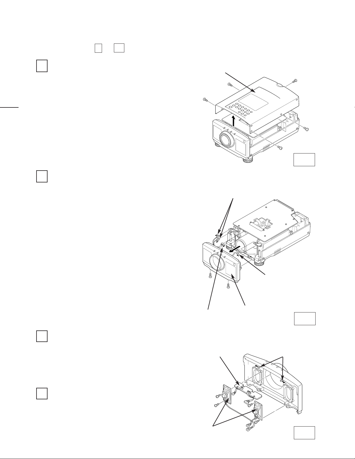
Remove 4 screws on side cabinet and 1 screw
on rear.
Grasp the two sides, pull the cabinet top
upward and remove.
LENS REPLACEMENT PROCEDURE
REMOVE THE CABINET TOP (See figure-1)
1
1.
2.
2
Fig-1
REMOVE THE CABINET FRONT (See figure-2)
Remove 2 screws on cabinet front bottom.
Grasp the two sides, pull the cabinet front
forward and remove.
Remove 2 speaker connectors, LED
connector "K8K", remote control pre-amp.
connector "K18D" and remove the cabinet
front completely.
1.
2.
3.
Fig-2
3
REMOVE THE LED UNIT AND SPEAKERS (See figure-3)
Release two hooks and pull out the LED unit.
Remove 4 screws and then remove the
speakers.
1.
2.
Fig-3
MOUNT T THE LED UNIT AND SPEAKERS
4
CABINET TOP
SPEAKER CONNECTORS
REMOTE CONTROL PRE-
AMP. CONNECTOR "K18D"
CABINET FRONT
LED CONNECTOR "K8K"
SPEAKERS
LED UNIT
Mount the LED unit and speakers to the new
cabinet front.
Perform the steps
to
for lens replacement.
1
10
HOOKS
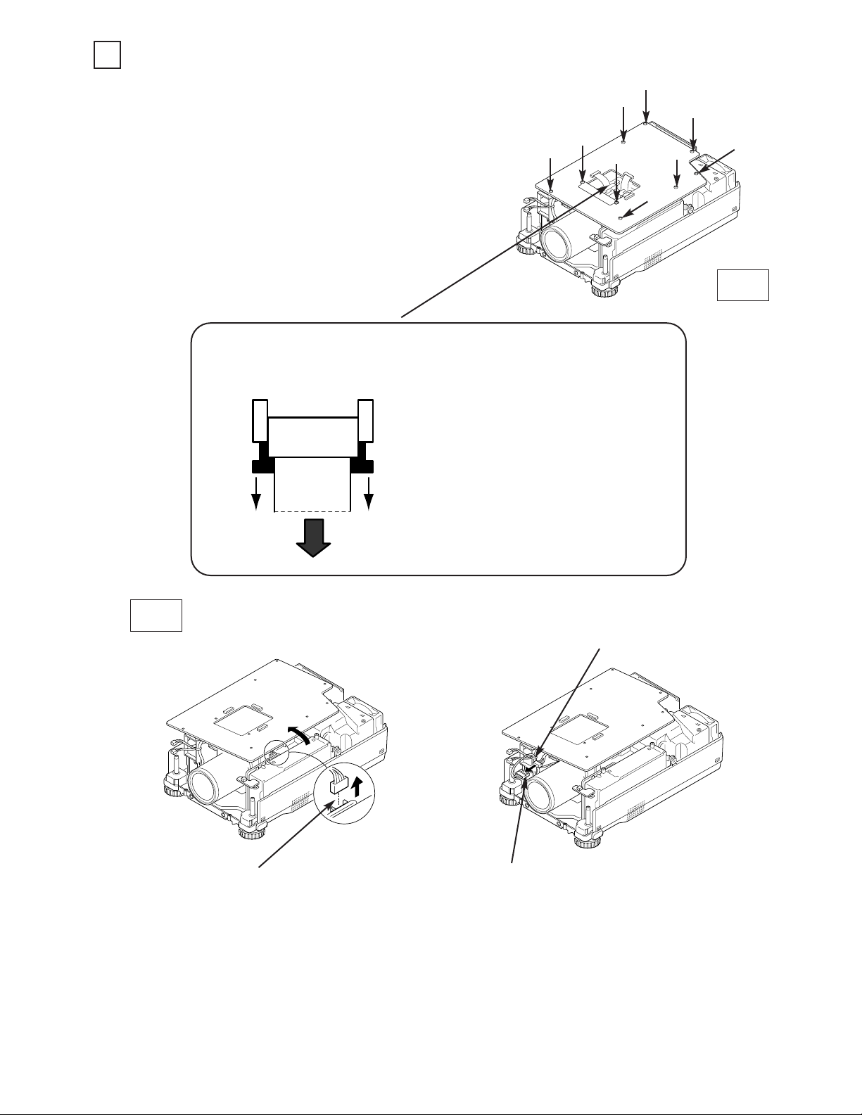
Remove 7 screws-A, 2 screws-B and
disconnect the 3 FPC cables of LCD panels.
Grasp the two sides, pull the Main unit upward.
Disconnect the lens motor connector "K16S"
from the circuit board.
REMOVE THE LENS MOTOR CONNECTOR (See figure 4, 5)
5
1.
2.
3.
Fig-4
A
A
A
A
A
A
A
B
B
Cut the wire band and remove the
lens motor lead.
LENS MOTOR CONNECTOR "K16S"
LENS MOTOR CONNECTOR "K16S"
Fig-5
FPC CABLE REMOVAL
CONNECTOR
FPC
CABLE
CABLE
LOCK
When disconnecting the FPC cable, pull out
the cable lock from the connector and then
disconnect the FPC cable.
Connector position is different depend
on the models. (See figure-5)
NOTE:
 Loading...