

Page 1

IP Proprietary Telephone
Quick Reference Guide
Model No.
KX-NT265
Important Information
When using the KX-NT265, keep the following conditions in mind.
If the unit does not operate properly, disconnect the unit from the Ethernet cable and then connect
•
again.
If you are having problems making calls, unplug the Ethernet cable and connect a known working
•
IP Proprietary Telephone (IP-PT). If the known working IP-PT operates properly, have the defective
IP-PT repaired by an authorised Panasonic Factory Service Centre. If the known working IP-PT
does not operate properly, check the Hybrid IP-PBX and the Ethernet cable.
Wipe the unit with a soft cloth. Do not clean the unit with abrasive powders or with chemical agents
•
such as benzene or thinner.
Use only the correct Panasonic handset.
•
Do not disassemble this unit. Dangerous electrical shock could result. The unit must only be
•
disassembled and repaired by qualified service technicians.
If damage to the unit exposes any internal parts, immediately disconnect the cable or cord. If the
•
power is supplied from the network to the IP-PT [Power-over-Ethernet], disconnect the Ethernet
cable. Otherwise, disconnect the AC adaptor cord. Then return this unit to a service centre.
Never attempt to insert wires, pins, etc. into the vents or other holes of this unit.
•
This unit is designed to aid the visually handicapped to locate dial keys and buttons.
•
•
This unit is designed to be installed under controlled conditions of ambient temperature and a
relative humidity.
Avoid installing the unit in damp or humid environments, such as bathrooms or swimming pools.
•
999 and 112 can be dialled on the product after accessing the CO line for the purpose of making
•
outgoing calls to the BT emergency (999) and (112) services (United Kingdom only).
Take special care to follow the safety suggestions listed below.
Safety
1) The unit should only be connected to a power supply of the type described in the Quick
Reference Guide or as shown on the label on the unit.
2) When left unused for a long period of time, the optional AC adaptor should be unplugged
from the AC outlet, if you are using Power-over-Ethernet, disconnect the Ethernet cable.
Installation
Environment
1) Do not use this unit near water, for example, near a bathtub, washbowl or sink. Damp
basements should also be avoided.
2) Keep the unit away from heating appliances and devices that generate electrical noise,
such as fluorescent lamps, motors and televisions. These noise sources can interfere
with the performance of the unit. It also should not be placed in rooms where the
temperature is less than 5 ˚C or greater than 40 ˚C.
Placement
1) Do not place heavy objects on top of this unit.
2) Care should be taken so that objects do not fall onto, and liquids are not spilled into, the
unit. Do not subject this unit to excessive smoke, dust, moisture, mechanical vibration,
shock or direct sunlight.
3) Place the unit on a flat surface.
Page 2

Important Information
WARNING:
TO PREVENT POSSIBLE FIRE OR ELECTRIC SHOCK, DO NOT EXPOSE
THIS UNIT TO RAIN OR MOISTURE.
THIS HANDSET EARPIECE IS MAGNETISED AND MAY RETAIN SMALL FERROUS
OBJECTS.
UNPLUG THIS UNIT FROM POWER OUTLET/THE ETHERNET CABLE IF IT EMITS
SMOKE, AN ABNORMAL SMELL OR MAKES UNUSUAL NOISE.
THESE CONDITIONS CAN CAUSE FIRE OR ELECTRIC SHOCK. CONFIRM THAT
SMOKE HAS STOPPED AND CONTACT AN AUTHORISED SERVICE CENTRE.
IMPORTANT NOTICE:
• Under power failure conditions, the IP-PT may not operate. Please ensure that a
separate telephone, not dependent on local power, is available for use in remote
sites in case of emergency.
• For information regarding network setup of the IP-PT such as IP address, please
refer to the Installation Manual for the Panasonic Hybrid IP-PBX.
• If an error message is shown on your display, consult the network administrator.
• The firmware of the KX-NT265 is protected by copyright laws and international
treaty provisions, and all other applicable laws. It can not be reverse engineered,
decompiled or disassembled.
This unit is capable of being used in conjunction with hearing aids fitted
with inductive coil pick-ups. The handset should be held as for normal
conversation. For operation, the hearing aid should be set to its “T”
position or as directed in the operating instructions for the hearing aid.
Note:
In this manual, the suffix of each model number is omitted.
Trademark:
Ethernet is either a registered trademark or a trademark of Xerox Corporation in
the United States and/or other countries.
This model supports the following PBX and IP-EXT card versions:
KX-TDA100/KX-TDA200: PMPR Software File Version 3.0000 or later
KX-TDA600: PLMPR Software File Version 3.0000 or later
KX-TDA0470(IP-EXT16): PIPEXT Software Version 1.001 or later/
PVOIPEX Software Version 1.011 or later
— 2 —
Page 3
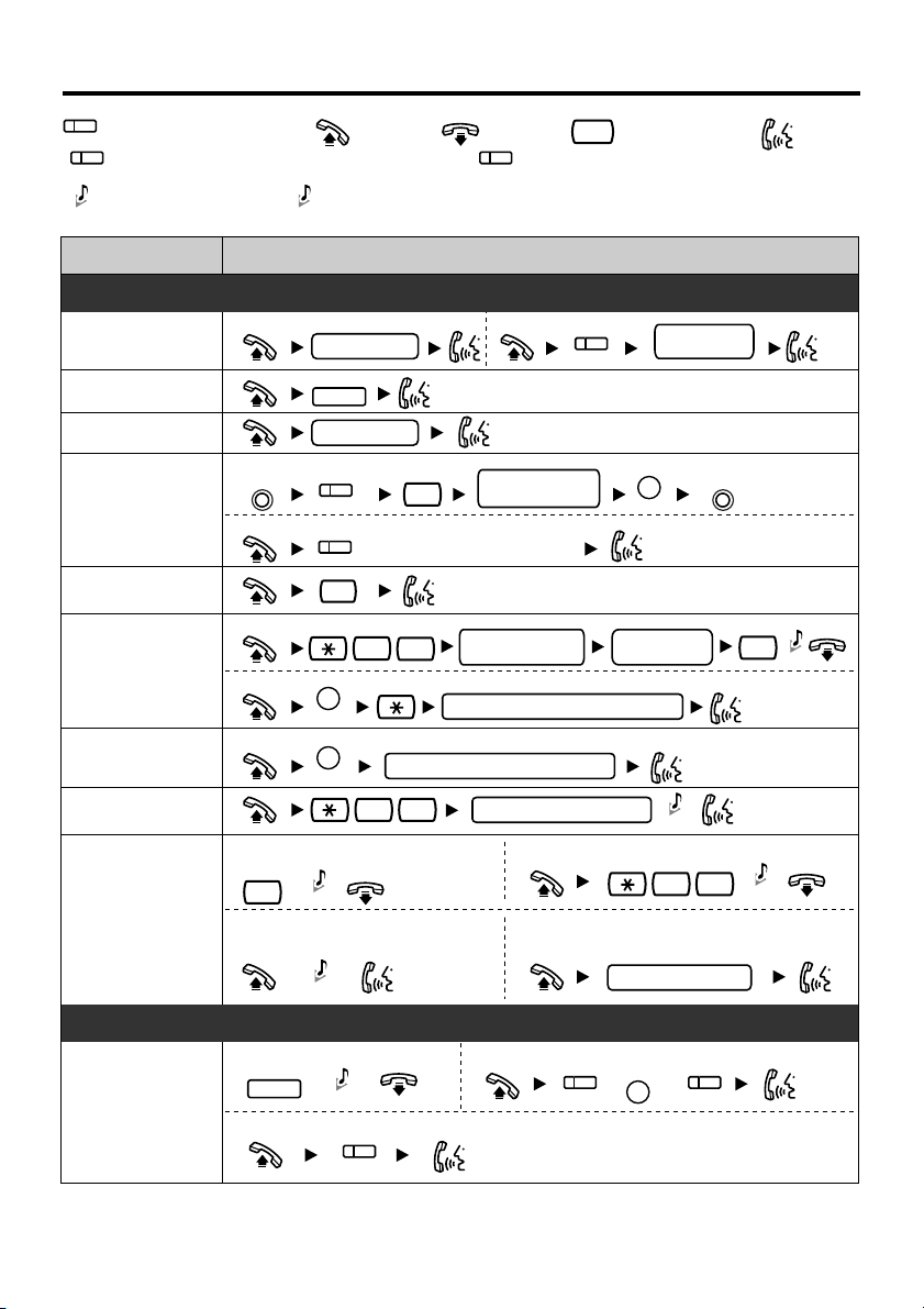
Features List
(CO)
Incoming Call Distribution Group button
(ICD Group)
Confirmation Tone
C. Tone
R.B. Tone
Feature
To an extension
Calling
Redial
Quick Dialling
To store
PROGRAM PROGRAM
One-touch
Dialling
To dial
Operator Call
To store
Personal
Speed Dialling
System
To dial
To dial
Speed Dialling
Doorphone Call
To set
While hearing a busy tone
Automatic
Callback Busy
Call Hold
6
To answer from an idle extension
While hearing a callback ring
To hold To retrieve a call at the holding extension
HOLD
To retrieve an outside call from another extension
Off-hookOutside (CO) Line button
Ringback Tone
Making Calls
Making Calls
extension no.
REDIAL
quick dial no.
(CO)
2
assigned as a One-touch
Dialling button
0
3
0
AUTO DIAL
STORE
AUTO DIAL
STORE
system speed dial no. (3 digits)
3 1
C. Tone
R.B. Tone
During a Conversation
C. Tone
(CO)
On-hook Feature number
Direct Station Selection button
(DSS)
Operation
To an outside party
(CO)
desired no.
(max. 32 digits)
personal speed
dial no. (2 digits)
personal speed dial no. (2 digits)
doorphone no. (2 digits)
To cancel
To answer from an idle outside line
While hearing a callback ring
(CO)
phone no.
AUTO DIAL
STORE
desired no.
(max. 32 digits)
C. Tone
4 6
outside phone no.
INTERCOM
//
outside
(ICD Group)
#
C. Tone
Talk
C. Tone
— 3 —
Page 4
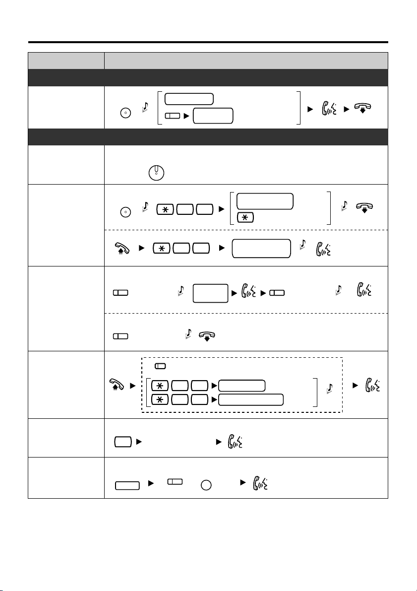
Features List
Feature Operation
During a Conversation
Call Transfer
Off-hook Monitor
Call Park
Multiple Party
Conversation
Call Pickup
TRANSFER
C. Tone
extension no.
(CO)
To an extension
outside
phone no.
To an outside party
Useful Features
To set/cancel
To set
TRANSFER
C. Tone
To retrieve
To add other parties during a conversation
assigned as a
CONFERENCE
button
To leave a conference
assigned as a
CONFERENCE
button
During a conversation using the handset
SP-PHONE
parking zone no.
5 2
stored parking
zone no.
Talk to the
new party.
extension no.
group no. (2 digits)
(DSS)
5 2
C. Tone
C. Tone
4 1
4 0
desired
phone no.
(2 digits)
(2 digits)
Specified
Auto
C. Tone
assigned as a
CONFERENCE
button
Directed
Group
C. Tone
C. Tone
C. Tone
Talk with
multiple parties.
Sending a Call
Waiting Tone
Answering a
Call Waiting
*
Disregard this step if both parties are extensions.
While hearing a busy tone
1
Wait for an answer.
To hold the current call then talk to the new party
HOLD
(CO)
/
INTERCOM
— 4 —
*
Page 5

Features List
Feature Operation
Useful Features
Paging
Message
Waiting
To page
3 3
To answer
4 3
To allow/deny a paged announcement
7 2 1
7 2 1
To leave a message waiting indication
Caller
Called
When the called extension is busy or does not answer
MESSAGE
To call back
extension
paging group
no. (2 digits)
C. Tone
C. Tone
MESSAGE
Wait for
C. Tone
Announce.
Deny
1
Allow
0
C. Tone
an answer.
C. Tone
Log-in/Log-out
Setting Absent
Message
Call
Forwarding
To set
To cancel
2
3
4
5
0
For Log-in
1736
For Log-out
0736
Before Leaving Your Desk
7 5 0
7 5 0
7
All calls
Busy
No answer
Busy/
No answer
Cancel
1
message no.
(1-9)
0
0
1
2
extension no.
CO line
access no.
extension no.
parameter
(if required)
Both Calls
Outside Calls
Intercom Calls
OR
outside
phone no.
ICD Group
Specified
All
#
#
C. Tone
C. Tone
— 5 —
Page 6

Features List
Feature
Extension
Dial Lock
Do Not Disturb
Extension
Feature Clear
Timed
Reminder
Receiving
Call Waiting
Operation
Before Leaving Your Desk
To lock
7 7 1
To unlock
7 7 0
C. Tone
extension PIN
(max. 10 digits)
C. Tone
Setting the Telephone According to Your Needs
Both Calls
0
Outside Calls
C. Tone
1
Intercom Calls
2
C. Tone
C. Tone
0
1
3
0
1
12 H
hour/minute
(4 digits)
24 H
hour/minute
(4 digits)
No Call
Tone
Whisper OHCA
No tone
Tone
7 1
7 9 0
To set
7 6 0 1
once
0
daily
1
To cancel To stop or answer the ring back
7 6 0 0
To set/cancel for intercom calls
7 3 1
To set/cancel for outside calls
7 3 2
INTERCOM
1
0
/
C. Tone
Set
Cancel
0
1
C. Tone
C. Tone
AM
PM
•
Consult your dealer for more details about the feature numbers.
• You can change the flexible CO buttons to the feature buttons.
• “Location of Controls” is shown on page 7.
— 6 —
Page 7

Location of Controls
LCD (Liquid Crystal Display)
PROGRAM: Used to enter and exit the
personal programming mode.
TRANSFER: Used to transfer a call to
another party.
INTERCOM: Used to make or receive
intercom calls.
VOLUME Control Button: Used to
adjust the volume.
AUTO ANS (Auto Answer)/MUTE:
Used to receive an incoming call in
hands-free mode or mute the
microphone/handset during a
conversation.
Setting
Ringer volume
While on-hook or receiving a call
Press UP or DOWN.
*
The ring tone pattern of patterns 09 to 30 is the same as pattern 01.
LCD Contrast/Headset Mode
While on-hook
LCD Contrast
0 1
Headset Mode
6
1
16
AUTO DIAL/STORE: Used for
System/Personal Speed Dialling or
storing programme changes.
15
Headset Jack
REDIAL: Used to redial the last dialled
14
number.
FLASH/RECALL: Used to disconnect
the current call and make another call
without hanging up.
HOLD: Used to place a call on hold.
Microphone: Used for the hands-free
conversation.
SP-PHONE (Speakerphone): Used for
the hands-free operation.
14
Flexible Outside (CO) Line Buttons:
Used to make or receive an outside call.
Pressing this button seizes an idle
outside line automatically. (Button
assignment is required.)
Also used as feature buttons. (Button
assignment is required.)
1515
MESSAGE: Used to leave a message
waiting indication or call back the party
who left the message waiting indication.
1616
Message/Ringer Lamp: When you
receive a call, the lamp flashes red.
When someone has left you a message,
the lamp stays on red.
Ring Tone
PROGRAM PROGRAM
AUTO DIAL
STORE
(CO)
OR
INTERCOM
Press Twice.
Press UP or DOWN.
0 1
0 8
*
AUTO DIAL
STORE
AUTO DIAL
STORE
PROGRAMPROGRAM
— 7 —
Page 8

Settings on the Programming Mode
To exitTo enter the programme mode
PROGRAM PROGRAM
Operation
Loop-CO
CO
(L-CO)
Single-CO
(S-CO)
Direct Station
CO
CO
Selection
One-touch
CO
Dialling
Incoming Call
CO
Distribution
Group (ICD
Group)
Preferred Line
Assignment-Outgoing
CO line no.
0
extension
1
no.
2
desired no.
3
0
ICD Group no.
9
1
FWD/DND
- Both calls
FWD/DND
- Outside calls
FWD/DND
-
Intercom calls
Account
Conference
Log-in/
Log-out
0
1
+
CO button no.
2
INTERCOM
3
/
CO
CO
CO
CO
CO
CO
CO
/
4
1
4
2
4
3
4
8
4
9
5
5
No line
An idle outside line
A CO/ICD Group
button
Intercom
Preferred Line
Assignment-Incoming
Alternate ReceivingRing/Voice
Call Waiting for
Outside calls
Call Waiting
Selection
Call Waiting Tone
Type Selection
Extension PIN
[Personal Identification
Number]
(PIN-max.10 digits)
Station Programming
Data Default Set
2
2 1
3 0
3 1
3 2
9 0
#
CO
/
1
/
No line
The longest
ringing line
An assigned
outside button
Yes (Tone)
Whisper OHCA
3
same PIN
0
0
1
+
2
CO button no.
Ringing (Tone Call)
0
(Voice Call)
Directly
1
Ring only
2
No (No tone)
0
No Call Tone
0
Tone 1 Tone 2
0
To set an extension PIN
extension PIN same PIN
To change a stored extension PIN to new one
stored extension PIN
/
1
/
1
/
new PIN
#
— 8 —
Page 9

Tilt Angle
The tilt angle of the unit can be adjusted.
To adjust the angle, insert the stand into the desired holes as shown below.
< LOW > < HIGH >
Connection
CAUTION
Ensure the cords are
inserted in the grooves to
prevent damage to the
connector. Some thick
cables may not fit in the
grooves.
< Back view>
To a Switching Hub (
LAN
).
Ethernet cable (Straight CAT 5 or higher cable) [not included]
To the optional AC adaptor (not included).
USE ONLY WITH Panasonic AC ADAPTOR.
Headset Jack
Headset (not included)
Do not use a KX-T7090 headset
*
CAUTION
Ensure the headset
cord is inserted in
the hook to prevent
damage to the
connector.
— 9 —
Page 10

Connection
*AC adaptor Order No.
United Kingdom: KX-A237E (PQLV1E)/Greece: KX-A237CE (PQLV1CE)
CAUTION:
The AC adaptor is used as the main disconnect device. Ensure that the AC outlet is located near
the unit and is easily accessible.
Note:
Consult your dealer for more details about the AC adaptor.
Wall Mounting
1
Pull down the handset hook until it locks,
so the tab holds the handset.
2
Remove the attached stand.
2
1
3
Mount the unit on the wall.
83 mm
To temporarily place the handset down
during a conversation, hook it over the top
edge of the phone as shown.
— 10 —
Page 11

Wall Mounting
If you are using the Ethernet cable with boots, you can mount the unit
on a wall using the wall mounting plate (included) by following the
steps below.
To AC Outlet
Ethernet cable (Straight CAT 5 or higher cable) [not included]
To a Switching Hub (LAN)
1
Install 2 screws spaced 83 mm or 100
mm apart, to the wall.
2
Insert the upper and lower tabs
of the wall mounting plate (included)
into the designated openings in the
base unit, then slide it in the direction
of the arrow until it clicks.
83 mm
100 mm
for base unit
3
Mount the base unit securely on the wall.
83 mm
100 mm
Screw
— 11 —
Page 12

Information
Information on Disposal for Users of Waste Electrical & Electronic Equipment
(private households)
This symbol on the products and/or accompanying documents means that used electrical
and electronic products should not be mixed with general household waste.
For proper treatment, recovery and recycling, please take these products to designated
collection points, where they will be accepted on a free of charge basis. Alternatively, in
some countries you may be able to return your products to your local retailer upon the
purchase of an equivalent new product.
Disposing of this product correctly will help to save valuable resources and prevent any
potential negative effects on human health and the environment which could otherwise
arise from inappropriate waste handling. Please contact your local authority for further details of your
nearest designated collection point.
Penalties may be applicable for incorrect disposal of this waste, in accordance with national legislation.
For business users in the European Union
If you wish to discard electrical and electronic equipment, please contact your dealer or supplier for further
information.
Information on Disposal in other Countries outside the European Union
This symbol is only valid in the European Union.
If you wish to discard this product, please contact your local authorities or dealer and ask for the correct
method of disposal.
This product is intended to be connected to a Panasonic Hybrid IP-PBX only.
Panasonic Communications Company (U.K.) Ltd. declares that this equipment is in
compliance with the essential requirements and other relevant provisions of Radio &
Telecommunications Terminal Equipment (R&TTE) Directive 1999/5/EC.
Declarations of Conformity for the relevant Panasonic products described in this manual
are available for download by visiting: http://www.doc.panasonic.de
Contact:
Panasonic Services Europe
a Division of Panasonic Marketing Europe GmbH
Panasonic Testing Centre
Winsbergring 15, 22525 Hamburg, Germany
Copyright:
This material is copyrighted by Panasonic Communications Co., Ltd., and may be
reproduced for internal use only. All other reproduction, in whole or in part, is prohibited
without the written consent of Panasonic Communications Co., Ltd.
©2006 Panasonic Communications Co., Ltd. All Rights Reserved.
Panasonic Communications Company (U.K.) Ltd.
Pencarn Way, Duffryn, Newport, South Wales, NP10 8YE, United Kingdom
PSQX4009ZB KU0306SY1056(E/GR)
 Loading...