

Page 1
Compact Plain Paper Fax with Copier
Operating Instructions
Model No. KX-FP343AL
Please read these Operating
Instructions before using the unit
and save for future reference.
This model is designed to be
used only in Australia.
Page 2

Location of Controls
N
How to use the operating instructions
When following operating instructions, always keep the front cover page (next page) open so that you will
find easy reference to the buttons.
OPE
I
Page 3
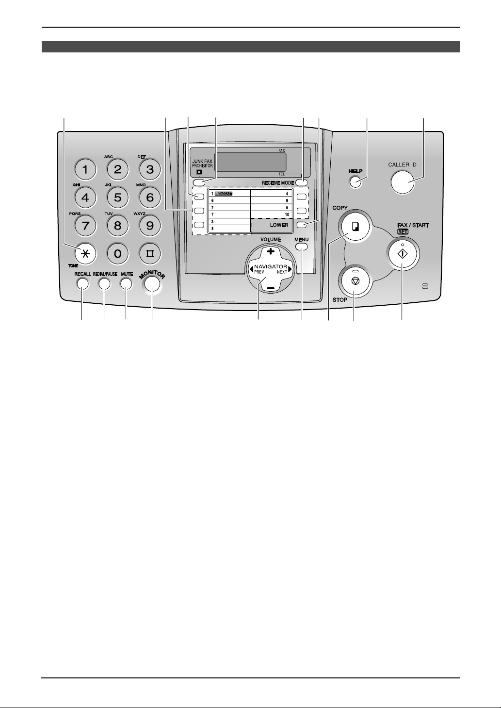
Location of controls
Please keep this page open when following operating instructions. For a description of each button, see
page 10.
F
A
B
DC
EGH
I
Keys (Listed in alphabetical order)
BROADCAST C LOWER F RECEIVE MODE E
CALLER ID H MENU N REDIAL/PAUSE J
COPY O MONITOR L SET Q
FAX/START Q MUTE K START Q
HELP G NAVIGATOR M STOP P
JUNK FAX PROHIBITOR D One-touch keys B TONE A
RECALL I VOLUME M
MNO
L
K
J
PQ
II
Page 4

Thank you for purchasing a Panasonic fax machine.
Things you should keep a record of
Attach your sales receipt here.
For your future reference
Date of purchase
Serial number (found on the rear of the unit)
Dealer’s name and address
Dealer’s telephone number
Caution:
L Note that the images of copied or received documents will remain on the used ink film. Use discretion
when disposing of the used ink film.
L Do not rub or use an eraser on the printed side of recording paper, as the print may smear.
L This model is designed for the Australian network.
Copyright:
L This manual is copyrighted by Panasonic Communications Co., Ltd. (PCC) and its licensee. Under
the copyright laws, this manual may not be reproduced in any form, in whole or part, without the prior
written consent of PCC and its licensee.
© Panasonic Communications Co., Ltd. 2003
2
Page 5

Warning:
●
Please ensure that a separate telephone, not dependent on local power, is available for emergency
use.
●
This equipment will be inoperable when mains power fails.
●
When a failure occurs which results in the internal parts becoming accessible,disconnect the power
supply cord immediately and return this unit to an authorised service centre.
●
Disconnect the telephone connection before disconnecting power connection prior to relocating the
equipment, and reconnect the power first.
●
To minimize the possibility of lightning damage, when you know that a thunderstorm is coming, we
recommend that you:
A. Unplug the telephone line cord from the phone jack.
B. Unplug the power supply cord from the AC power outlet.
●
No “000” or other calls can be made from this device during a mains power failure.
●
The earcap on the handset is magnetised and may retain metallic objects.
3
Page 6
Important information
Instructions to customer
Installation
Attached to this apparatus is an approval label. This label is evidence that it is a “Permitted Attachment”
which has been authorised to be connected to your telephone service.
Conditions relating to connection and operation of this Permitted Attachment are contained in
Telecommunications General By-Law 220 (5).
You are authorised to install this Permitted Attachment yourself by plugging it into the line socket of any
regular telephone. You may connect it in place of your existing telephone or to any spare telephone
socket installed in your premises.
To disconnect your existing telephone you must first remove its plug from the line socket. You can then
insert the plug of your Permitted Attachment into the socket and use your equipment.
If the plug of your existing telephone cannot be readily removed, you will have to remove the screw
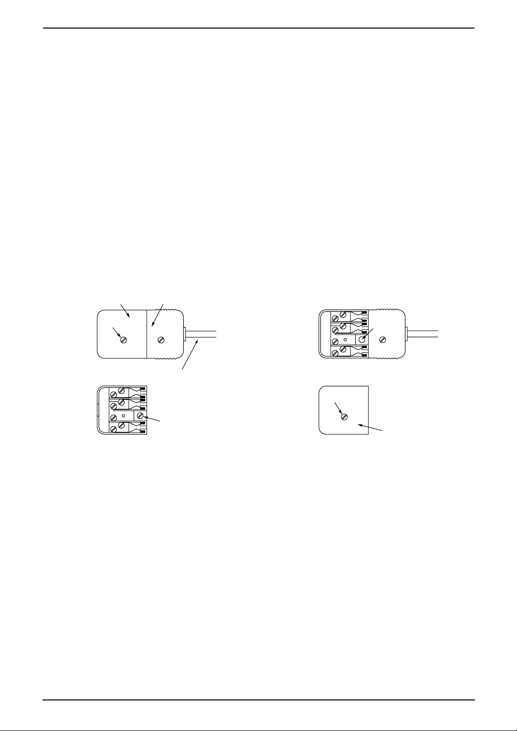
securing it. To do this proceed as follows:
1. Loosen screw “A” sufficiently to remove the socket cover. (See Fig. 1.)
2. Remove screw “B” and withdraw the plug. (See Fig. 2.)
3. Replace screw “B”. (See Fig. 3.) Ensure that it screws completely into the socket recess. (If the screw
is too long, increase the hole depth or replace the screw with one 5 mm shorter.)
4. Replace socket cover and tighten screw “A”. (See Fig. 4.)
SOCKET
SCREW “A”
If you are satisfied with the operation of your telephone service after plugging in your Permitted
Attachment, your installation is completed.
You will be unable to connect this Permitted Attachment if your telephone service consists only of a wall
phone or an old style telephone which is not connected by means of a modern plug and socket. In such
cases a new socket will need to be installed.
Should the Permitted Attachment not operate when plugged into a socket, it is either faulty or unsuitable
for operation with your telephone service. It should be returned to the store where purchased.
Fig. 1
Fig. 3
PLUG
Fig. 2
TELEPHONE CORD
Connect to the PLUG
( )
as shown in Fig. 1.
SCREW
“B”
SCREW “A”
Fig. 4
SCREW
“B”
SOCKET
Service difficulties
If at any time a fault occurs on your telephone service carry out the following checks before you call for
service:
L Disconnect the Permitted Attachment and try using the service with the normal telephone.
L If the telephone service then operates satisfactorily, the fault is in your Permitted Attachment. Leave
the Permitted Attachment disconnected and report the fault to its supplier or agent to arrange for
repair.
L If when using the telephone the service is still faulty, report the fault to “Service Difficulties and Faults”
for attention.
You are required to keep this Permitted Attachment in good working order while it is connected to your
telephone service. Its construction or internal circuit must not be modified in any way without permission.
4
Page 7

Safety Instructions
Safety InstructionsSafety Instructions
Important safety instructions
When using this unit, basic safety precautions
should always be followed to reduce the risk of
fire, electric shock, or personal injury.
1. Read and understand all instructions.
2. Follow all warnings and instructions marked
on this unit.
3. Unplug this unit from power outlets before
cleaning. Do not use liquid or aerosol
cleaners. Use a damp cloth for cleaning.
4. Do not use this unit near liquid-for example,
near a bath tub, washbowl, sink, etc. Damp
basements should also be avoided. The unit
should be kept away from heat sources such
as heaters, kitchen stoves, etc. It also should
not be placed in rooms where the
temperature is less than 5°C or greater than
35°C.
5. Place the unit securely on a stable surface.
Serious damage and/or injury may result if
the unit falls.
6. Do not cover slots and openings on the unit.
They are provided for ventilation and
protection against overheating. Never place
the unit near radiators, or in a place where
proper ventilation is not provided.
7. Use only the power source marked on the
unit. If you are not sure of the type of power
supplied to your home, consult your dealer or
local power company.
8. For safety purposes this unit is equipped with
a grounded plug. If you do not have this type
of outlet, please have one installed. Do not
defeat this safety feature by tampering with
the plug.
9. Do not place objects on the power cord.
Install the unit where no one can step or trip
on the cord.
10.Do not overload power outlets and extension
cords. This can result in the risk of fire or
electric shock.
11.Never push any objects through slots in this
unit. This may result in the risk of fire or
electric shock. Never spill any liquid on the
unit.
12.To reduce the risk of electric shock, do not
disassemble this unit. Take the unit to an
authorised service centre when service is
required. Opening or removing covers may
expose you to dangerous voltage or other
risks. Incorrect reassembly can cause
electric shock when the unit is subsequently
used.
13.Unplug this unit from the power outlets and
refer servicing to an authorised service
centre when the following conditions occur:
A. When the power cord is damaged or
frayed.
B. If liquid has been spilled into the unit.
C. If the unit has been exposed to rain or
water.
D. If the unit does not work normally by
following the operating instructions.
Adjust only controls covered by the
operating instructions. Improper
adjustment may require extensive work
by an authorised service centre.
E. If the unit has been dropped or physically
damaged.
F. If the unit exhibits a distinct change in
performance.
14.During thunderstorms, avoid using
telephones except cordless types. There may
be a remote risk of an electric shock from
lightning.
15.Do not use this unit to report a gas leak, when
in the vicinity of the leak.
SAVE THESE
INSTRUCTIONS
INSTALLATION:
L Never install telephone wiring during a
lightning storm.
L Never install telephone jacks in wet locations
unless the jack is specifically designed for
wet locations.
L Never touch uninsulated telephone wires or
terminals unless the telephone line has been
disconnected at the network interface.
L Use caution when installing or modifying
telephone lines.
WARNING:
L To prevent the risk of fire or electrical shock,
do not expose this product to rain or any type
of moisture.
OTHER INFORMATION:
L Keep the unit away from electrical noise
generating devices, such as fluorescent
lamps and motors.
L The unit should be kept free from dust, high
temperature and vibration.
5
Page 8

Safety Instructions
L The unit should not be exposed to direct
sunlight.
L Do not place heavy objects on top of this unit.
L Do not touch the plug with wet hands.
L Wipe the outer surface of the unit with a soft
cloth. Do not use benzine, thinner, or any
abrasive powder.
6
Page 9

Table of Contents
1. Table of Contents
1. Introduction and
Installation
Accessories
1.1 Included accessories..........................8
1.2 Accessory information ........................9
Finding the Controls
1.3 Overview ..........................................10
1.4 Description of buttons....................... 10
Installation
1.5 Ink film ..............................................11
1.6 Paper tray .........................................13
1.7 Recording paper support.................. 13
1.8 Recording paper...............................13
2. Preparation
Connections and Setup
2.1 Connections .....................................14
Help Button
2.2 Help function ....................................15
Vo lu me
2.3 Adjusting volume ..............................15
Initial Programming
2.4 Date and time ...................................16
2.5 Your logo...........................................17
2.6 Your fax number ...............................18
3. Telephone
Automatic Dialling
3.1 Storing names and telephone numbers
into the one-touch dial and navigator
directory............................................ 20
3.2 Making a phone call using the one-
touch dial and navigator directory ....21
Caller ID
3.3 Caller ID service ...............................21
3.4 Viewing and calling back using caller
information........................................ 22
3.5 Storing caller information into the one-
touch dial and navigator directory ....23
4. Fax
Sending Faxes
4.1 Sending a fax manually ....................24
4.2 Documents you can send.................25
4.3 Sending a fax using the one-touch dial
and navigator directory.....................25
4.4 Broadcast transmission ....................26
Receiving Faxes
4.5 Selecting the way to use your fax
machine............................................28
4.6 Receiving a fax manually..................29
4.7 Receiving a fax automatically...........30
4.8 Using the unit with an answering
machine............................................30
4.9 Receive polling (retrieving a fax placed
on another fax machine)................... 31
4.10 Junk fax prohibitor (preventing fax
reception from undesired callers) .....31
5. Distinctive Ring
Distinctive Ring
5.1 Using with the ring detection feature 33
6. Copy
Copying
6.1 Making a copy .................................. 34
7. Programmable Features
Features
7.1 Programming....................................36
7.2 Basic features................................... 36
7.3 Advanced features............................ 37
8. Help
Error Messages
8.1 Error messages – Reports ...............40
8.2 Error messages – Display ................ 40
Frequently Asked Questions
8.3 When a function does not work, check
here .................................................. 41
Jams
8.4 Recording paper jam ........................ 44
8.5 Document jams – sending................ 46
Cleaning
8.6 Document feeder cleaning................46
8.7 Thermal head cleaning.....................47
9. General Information
Printed Reports
9.1 Reference lists and reports ..............49
Specifications
9.2 Technical data about this product..... 50
10.Index
10.1 Index................................................ 52
7
Page 10
1. Introduction and Installation
1Int roduction and Installation
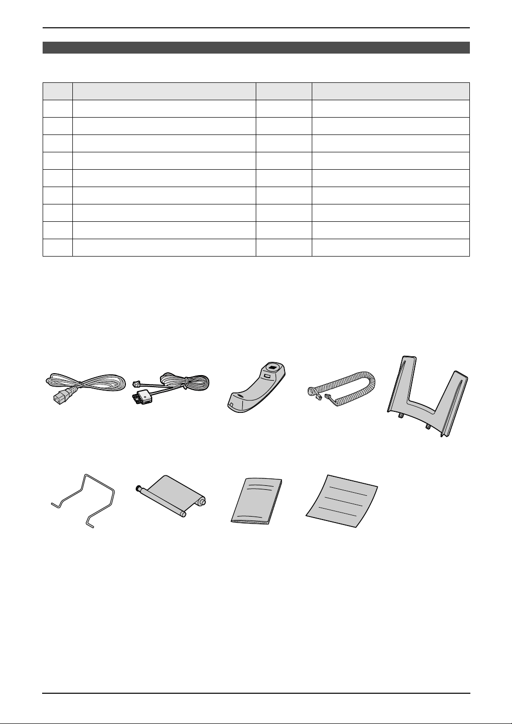
1.1 Included accessories
No. Item Quantity Specifications
1 Power cord 1 ----------
2 Telephone line cord 1 ----------
3 Handset 1 ----------
4 Handset cord 1 ----------
5 Paper tray 1 ----------
6 Recording paper support 1 ----------
7 Ink film (10 metres long) 1 prints about 30 A4-sized pages.
8 Operating instructions 1 ----------
9 Quick start sheet 1 ----------
*1 For replacement film, see page 9.
Note:
L If any items are missing or damaged, check with the place of purchase.
L Save the original carton and packing materials for future shipping and transportation of the unit.
L The pictures and illustrations in these instructions may vary slightly from the actual product.
*1
12345
6789
8
Page 11

1. Introduction and Installation
1.2 Accessory information
1.2.1 Available accessories
Model No. Item Specifications/Usage
KX-FA57E Replacement film
*1 We recommend that you buy a full-size replacement film for continuous use of your unit. Please use
genuine Panasonic replacement film. The ink film is not reusable. Do not rewind and use the ink
film again.
*1
216 mm × 70 m (prints about 210 A4-sized
pages.)
9
Page 12
1. Introduction and Installation
Finding the Controls
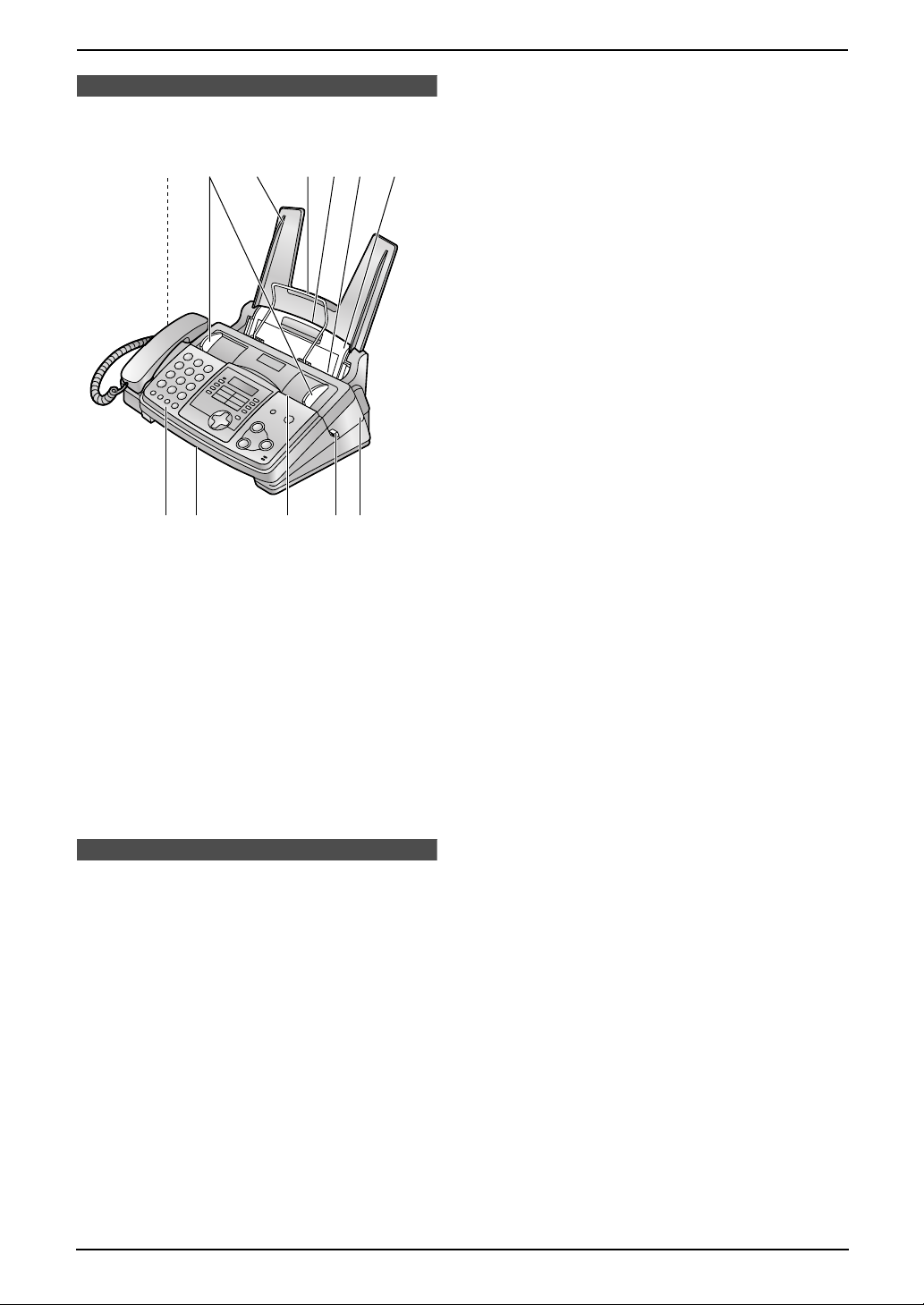
1.3 Overview
2456731
j lk98
1 Speaker
2 Document guides
3 Paper tray
4 Recording paper support
5 Recording paper entrance
6 Recording paper exit
7 Tension plate
8 Front cover
9 Document exit
j Document entrance
k Green button (Back cover release button)
l Back cover
1.4 Description of buttons
L Keep the front cover page open for button
locations.
A {TONE}
L To change from pulse to tone temporarily
during dialling when your line has rotary
pulse services.
B One-touch keys
L To use one-touch dial (page 20, 21, 25).
C {BROADCAST}
L To transmit a document to multiple parties
(page 26).
D {JUNK FAX PROHIBITOR}
L To use the junk fax prohibitor feature
(page 31).
E {RECEIVE MODE}
L To change the receiving mode (page 28).
F {LOWER}
L To select stations 6–10 for one-touch dial
(page 20, 21, 25).
G {HELP}
L To print a quick reference (page 15).
H {CALLER ID}
L To use Caller ID service (page 21, 22).
I {RECALL}
L To access special telephone services for
transferring extension calls.
J {REDIAL/PAUSE}
L To redial the last number dialled.
L To insert a pause during dialling.
K {MUTE}
L To mute your voice to the other party
during a conversation. Press this button
again to resume the conversation.
L {MONITOR}
L To initiate dialling without lifting the
handset.
M {NAVIGATOR}{VOLUME}
L To adjust volume (page 15).
L To search for a stored entry (page 21, 25).
L To select features or feature settings
during programming (page 36).
L To navigate to the next operation.
N {MENU}
L To initiate or exit programming.
O {COPY}
L To initiate copying (page 34).
P {STOP}
L To stop an operation or programming.
Q {FAX/START}{SET}
L To initiate fax transmission or reception.
L To store a setting during programming.
10
Page 13
1. Introduction and Installation
Installation
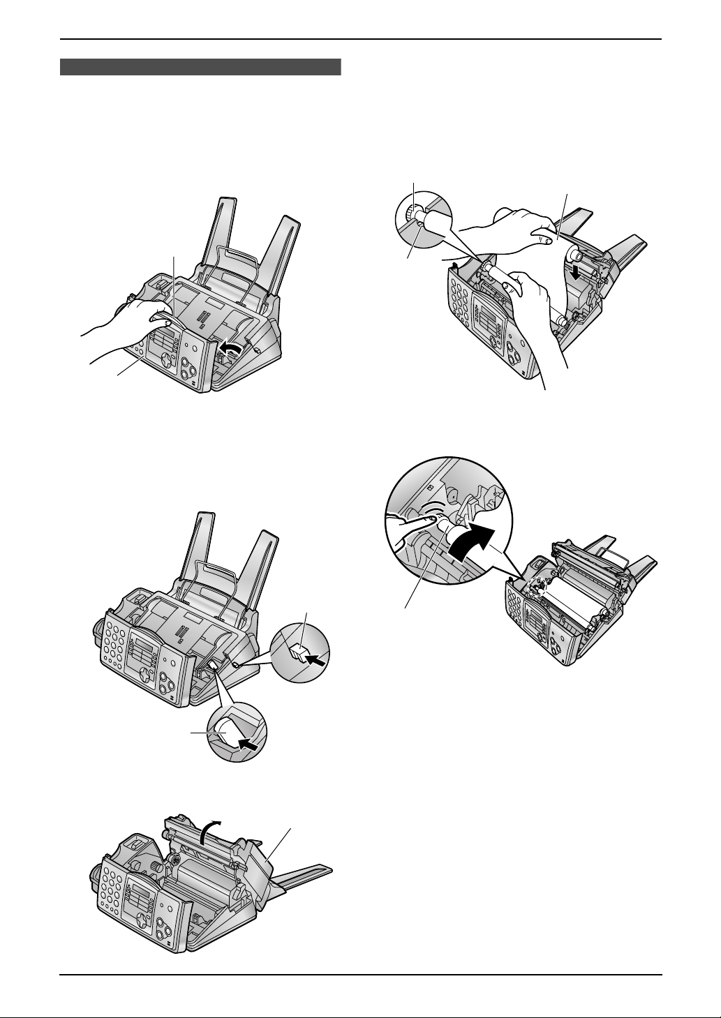
1.5 Ink film
1.5.1 Installing the ink film
1 Open the front cover (1) by pulling up the
centre part (2).
2
1
2 Release the back cover by pushing the green
button (1) on the right side of the unit.
OR
Release the back cover by pushing the green
lever (2) in the unit.
4 Insert the gear with the blue core of the front
ink film roll (1) into the left slot of the unit
(2).
Insert the rear ink film roll (3).
L The ink film is safe to touch, and will not
rub off on your hands like carbon paper.
1
3
2
5 Turn the gear with the blue core (1) in the
direction of the arrow.
2
3 Open the back cover (1).
1
1
1
11
Page 14
1. Introduction and Installation
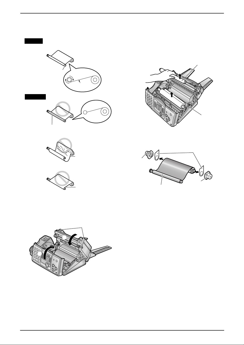
L Make sure that the ink film is wrapped
around the blue core (2) at least once.
Correct
2
1 turn
Tight
Incorrect
The ink film is not wrapped
around the blue core.
Slack/Crease
may occur from the use of non-Panasonic
replacement film.
1 Open the covers (see steps 1 to 3 on page
11).
2 Remove the used core (1) and used ink film
(2).
1
2
3 Remove the stoppers (1) and tags (2) from
the new ink film (3).
2
1
Reverse
6 First close the back cover securely (1) by
pushing down on the dotted area at both
ends (2). Then close the front cover
securely (3).
2
1
3
1.5.2 Replacing the ink film
The included film roll is a starter ink film. To
ensure that the unit operates properly, we
recommend the use of Panasonic replacement
film. See page 9 for accessory information.
L We cannot be responsible for any damage to
the unit or degradation of print quality which
3
1
4 Insert the ink film and close the covers (see
steps 4 to 6 on page 11).
12
Page 15
1. Introduction and Installation
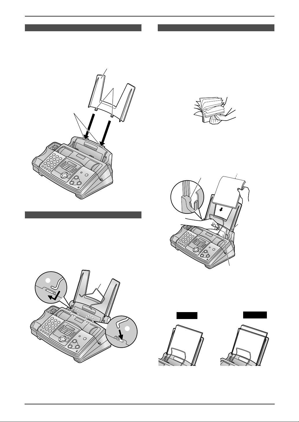
1.6 Paper tray
Insert the tabs (1) on the paper tray (2) into the
slots on the back of the unit (3).
2
1
3
1.8 Recording paper
The unit can hold up to 50 sheets of 75 g/m2
paper. See the note for paper specifications
(page 51).
1 Before inserting a stack of paper, fan the
paper to prevent paper jams.
2 Pull the tension plate forward (1) and hold
open while inserting the paper.
Side to be printed
face down.
2
1.7 Recording paper
support
Insert the recording paper support (1) into the
slot to the right of the recording paper exit (2),
then into the left slot (3).
3
L The recording paper will be ejected from the
top of the unit after printing. The recording
paper support prevents the printed paper
from curling.
1
2
Recording
paper
entrance
1
L The paper should not be over the tab
(2).
L If the paper is not inserted correctly,
readjust the paper, or the paper may jam.
Correct
Incorrect
13
Page 16
2. Preparation
2Pr eparationConnections and Set up
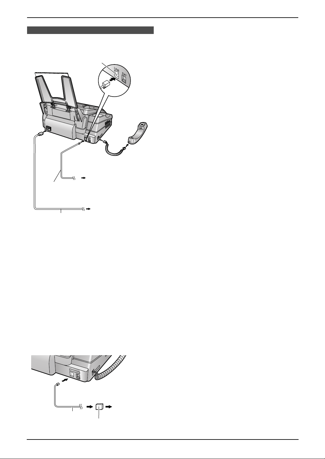
2.1 Connections
Connect to LINE.
To a single
telephone
Telephone
line cord
Power cord
line jack
To a power outlet
(220–240 V, 50/60 Hz)
Help Button
Caution:
L When you operate this product, the power
outlet should be near the product and
easily accessible.
L Be sure to use the telephone line cord
included in this unit.
L Do not extend the telephone line cord.
Note:
L If any other device is connected on the same
line, this unit may disturb the network
condition of the device.
L If you want to connect an answering machine
to this unit, see page 30.
L If you use the unit with a computer and your
internet provider instructs you to install a
filter, please connect it as follows.
To a single
Telephone
line cord
Filter
telephone
line jack
14
Page 17
2. Preparation
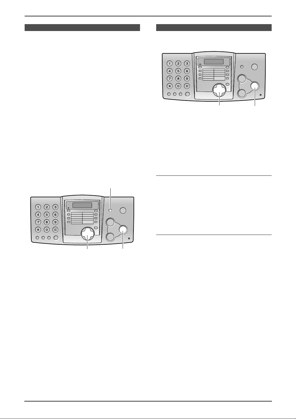
2.2 Help function
The unit contains helpful information which can
be printed for quick reference.
Quick set up:
How to set the date, time, your logo and fax
number.
Feature list:
How to program the features.
Directory:
How to store names and numbers in the
navigator directory and how to dial them.
Fax receiving:
How to set the unit to receive faxes.
Copier:
How to use the copier function.
Reports:
List of available reports.
Caller ID:
How to use the caller ID service.
{HELP}
2.3 Adjusting volume
{A}{B}
2.3.1 Ringer volume
4 levels (high/medium/low/off) are available.
While the unit is idle, press {A} or {B}.
L If any documents are in the document
entrance, you cannot adjust the ringer
volume. Confirm that there are no documents
in the entrance.
To turn the ringer off
1. Press {B} repeatedly to display “RINGER
OFF= OK?”.
2. Press {SET}.
L When a call is received, the unit will not ring
and will display “INCOMING CALL”.
L To turn the ringer back on, press {A}.
{SET}
{<}{>}
{SET}
1 Press {HELP}.
2 Press {<} or {>} repeatedly to display the
desired item.
3 Press {SET}.
L The selected item will be printed.
Volume
Ringer pattern
L You can select one of three ringer patterns for
external calls (feature #17, page 37).
2.3.2 Handset receiver volume
3 levels (high/middle/low) are available.
While using the handset, press {A} or {B}.
2.3.3 Monitor volume
8 levels (high to low) are available.
While using the monitor, press {A} or {B}.
15
Page 18
2. Preparation
Initial Programming
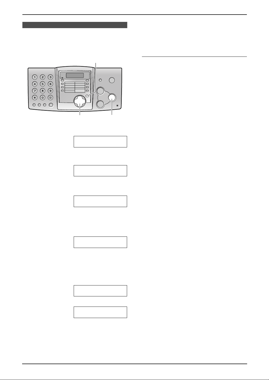
2.4 Date and time
You must set the date and time.
{MENU}
{<}{>}
1 Press {MENU}.
SYSTEM SET UP
PRESS NAVI.[()]
2 Press {<} or {>} repeatedly to display the
following.
SET DATE & TIME
{SET}
PRESS SET
Note:
L This information will be printed on each page
transmitted from your unit.
L The accuracy of the clock is approximately
±60 seconds a month.
To correct a mistake
Press {<} or {>} to move the cursor to the
incorrect number, and make the correction.
3 Press {SET}.
L Cursor (|) will appear on the display.
M:|01/D:01/Y:03
TIME: 12:00AM
4 Enter the current month/day/year by
selecting 2 digits for each.
Example: August 10, 2003
Press {0}{8} {1}{0} {0}{3}.
M:08/D:10/Y:03
TIME: |12:00AM
5 Enter the current hour/minute by selecting 2
digits for each. Press {*} to select “AM” or
“PM”.
Example: 3:15PM (12 hour clock entry)
1. Press {0}{3} {1}{5}.
M:|08/D:10/Y:03
TIME: 03:15AM
2. Press {*} repeatedly to display “PM”.
M:|08/D:10/Y:03
TIME: 03:15PM
6 Press {SET}.
L The next feature will be displayed.
7 Press {MENU} to exit the program.
16
Page 19

2.5 Your logo
The logo can be your company, division or name.
2. Preparation
4. Press {>} to move the cursor to the next
space and press {5} 3 times.
LOGO=BIL|L
{MENU}
{STOP}{MUTE}
{<}{>}{A}{B}
{SET}{RECALL}
1 Press {MENU}.
SYSTEM SET UP
PRESS NAVI.[()]
2 Press {<} or {>} repeatedly to display the
following.
YOUR LOGO
PRESS SET
3 Press {SET}.
L Cursor (|) will appear on the display.
LOGO=|
To change capital or lower-case letters
Pressing the {#} key will change to capital or
lower-case alternately.
1. Press {2} 2 times.
LOGO=|B
2. Press {4} 3 times.
LOGO=B|I
3. Press {#}.
LOGO=B|i
4. Press {5} 3 times.
LOGO=Bi|l
To correct a mistake
Press {<} or {>} to move the cursor to the
incorrect character, and make the correction.
To delete a character
Press {<} or {>} to move the cursor to the
character you want to delete and press {STOP}.
4 Enter your logo, up to 30 characters. See the
character table on page 17 for details.
5 Press {SET}.
L The next feature will be displayed.
6 Press {MENU} to exit the program.
Note:
L This information will be printed on each page
transmitted from your unit.
To enter your logo
Example: “BILL”
1. Press {2} 2 times.
LOGO=|B
2. Press {4} 3 times.
LOGO=B|I
3. Press {5} 3 times.
LOGO=BI|L
To insert a character
1. Press {<} or {>} to move the cursor to the
position to the right of where you want to
insert the character.
2. Press {MUTE} to insert a space and enter
the character.
To select characters with the dial keypad
Keys Characters
{1} 1[ ] { } +– /=
,._`:;?|
{2} ABCab c 2
{3} DEF d e f 3
{4} GHI g h i 4
{5} JKLj kl 5
{6} MNOmn o 6
{7} PQRSpqr s 7
17
Page 20

2. Preparation
Keys Characters
{8} TUVt uv8
2.6 Your fax number
{9} WX Y Z w x y z 9
{0} 0( ) <>! " #$
%& ¥ @ @^ ’ →
{#} To change capital or lower-
case letter.
{RECALL} Hyphen button
{MUTE} Insert button
{STOP} Delete button
Note:
L To enter another character located on the
same number key, press {>} to move the
cursor to the next space.
To select characters using {A} or {B}
Instead of pressing the dial keys, you can select
characters using {A} or {B}.
1. Press {A} or {B} repeatedly to display the
desired character.
2. Press {>} to move the cursor to the next
space.
L The character displayed is inserted.
3. Return to step 1 to enter the next character.
{MENU}
{RECALL} {STOP}
{<}{>}
{SET}
1 Press {MENU}.
SYSTEM SET UP
PRESS NAVI.[()]
2 Press {<} or {>} repeatedly to display the
following.
YOUR FAX NO.
PRESS SET
3 Press {SET}.
L Cursor (|) will appear on the display.
NO.=|
Display order of characters
Capital
alphabet
Number
Symbol
Lower-case
alphabet
: Pressing {A}
:
Pressing {B}
4 Enter your fax number, up to 20 digits.
Example: NO.=1234567|
5 Press {SET}.
L The next feature will be displayed.
6 Press {MENU} to exit the program.
Note:
L This information will be printed on each page
transmitted from your unit.
L The {*} button enters a “+” and the {#}
button enters a space.
Example: +64 9 1234567
Press {*}{6}{4}{#}{9}{#}{1}{2}{3}{4}
{5}{6}{7}.
L To enter a hyphen in a telephone number,
press {RECALL}.
To correct a mistake
Press {<} or {>} to move the cursor to the
incorrect number, and make the correction.
18
Page 21

To delete a number
Press {<} or {>} to move the cursor to the
number you want to delete and press {STOP}.
2. Preparation
19
Page 22

3. Telephone
3TelephoneAutomatic Dialling
3.1 Storing names and
telephone numbers into
the one-touch dial and
navigator directory
For rapid access to frequently dialled numbers,
the unit provides the one-touch dial (10 entries)
and navigator directory (100 entries).
L You can also send faxes using the one-touch
dial and navigator directory (page 25).
{LOWER}
{STOP}{<}{>}{A}{B}
{SET}{MENU}
3.1.1 Storing into the one-touch
dial
1 Press {MENU} repeatedly to display
“DIRECTORY SET”.
2 Select the desired station key.
For station 1:
1. Press station 1.
STATION 1
DIAL MODE [±]
2. Press {SET}.
For stations 2–5:
Press one of the station keys.
For stations 6–10:
Press {LOWER}, then press one of the
station keys.
3 Enter the name, up to 10 characters (see
page 17 for instructions).
4 Press {SET}.
7 Press {MENU}.
Helpful hints:
L You can confirm the stored entries in the
telephone number list (page 49).
Note:
L A hyphen or a space entered in a telephone
number counts as two digits.
To correct a mistake
Press {<} or {>} to move the cursor to the
incorrect character/number, and then make the
correction.
To delete a character/number
Press {<} or {>} to move the cursor to the
character/number you want to delete, and press
{STOP}.
3.1.2 Storing into the navigator
directory
1 Press {MENU} repeatedly to display
“DIRECTORY SET”.
2 Press {>}.
3 Enter the name, up to 10 characters (see
page 17 for instructions).
4 Press {SET}.
5 Enter the telephone number, up to 30 digits.
6 Press {SET}.
L To program other entries, repeat steps 3
to 6.
7 Press {MENU}.
Helpful hints:
L You can confirm the stored entries in the
telephone number list (page 49).
Note:
L If “SPACE= 5 DIRS.” is displayed, you can
store only 5 more entries.
L A hyphen or a space entered in a telephone
number counts as 2 digits.
To correct a mistake
Press {<} or {>} to move the cursor to the
incorrect character/number, and then make the
correction.
5 Enter the telephone number, up to 30 digits.
6 Press {SET}.
L To program other entries, repeat steps 2
to 6.
20
To delete a character/number
Press {<} or {>} to move the cursor to the
character/number you want to delete, and press
{STOP}.
Page 23

3. Telephone
3.1.3 Editing a stored entry
1 Press {>}.
2 Press {A} or {B} repeatedly to display the
desired entry.
3 Press {MENU}.
4 Press {*}.
L If you do not need to edit the name, skip
to step 6.
5 Edit the name (see the storing procedure on
page 20 for instructions).
6 Press {SET}.
L If you do not need to edit the telephone
number, skip to step 8.
7 Edit the telephone number. For further
details, see the storing procedure on page
20.
8 Press {SET}.
3.1.4 Erasing a stored entry
1 Press {>}.
2 Press {A} or {B} repeatedly to display the
desired entry.
3 Press {MENU}.
4 Press {#}.
L To cancel erasing, press {STOP}.
5 Press {SET}.
L The unit will start dialling automatically.
3.2.2 Using the navigator
directory
1 Press {>}.
2 Press {A} or {B} repeatedly to display the
desired entry.
3 Press {MONITOR} or lift the handset.
L The unit will start dialling automatically.
To search for a name by initial
Example: “LISA”
1. Press {>}.
2. Press {A} or {B} to initiate the navigator
directory.
3. Press {5} repeatedly to display any name
with the initial “L” (see the character table,
page 17).
L To search for symbols (not letters or
numbers), press {*}.
4. Press {A} repeatedly to display “LISA”.
L To stop the search, press {STOP}.
L To dial the displayed number, press
{MONITOR} or lift the handset.
Caller ID
3.3 Caller ID service
This unit is compatible with the Caller ID
service offered by your local telephone
company. To use this feature, you must
subscribe to a Caller ID service.
3.2 Making a phone call
using the one-touch dial
and navigator directory
Before using this feature, program the desired
names and telephone numbers into the onetouch dial and navigator directory (page 20).
L Keep the front cover page open for button
locations.
3.2.1 Using the one-touch dial
1 Press {MONITOR} or lift the handset.
2 Select the desired station key.
For stations 1–5:
Press the desired station key.
For stations 6–10:
Press {LOWER}, then press the desired
station key.
3.3.1 How Caller ID is displayed
The calling party’s name or telephone number
will be displayed after the first ring. You then
have the option of whether or not to answer the
call.
The unit will automatically store the caller
information. You can view it (page 22) and print
the caller ID list (page 49).
Note:
L If the unit is connected to a PBX (Private
Branch Exchange) system, you may not
receive the caller information. Consult your
PBX supplier.
L If the unit cannot receive caller information,
the following will be displayed:
“OUT OF AREA”: The caller dialled from an
area which does not provide Caller ID
service.
“PRIVATE CALLER”: The caller requested
not to send caller information.
21
Page 24

3. Telephone
L Although Telstra and Optus do not currently
send caller name information, the caller’s
name will be displayed as stored in the
directory, when a call from that caller is
received.
L The area code will need to be stored with the
8-digit telephone number.
To confirm caller information using the
Caller ID list
The unit will store information for the most recent
30 callers.
– To print manually, see page 49.
– To print automatically after every 30 new
calls, activate feature #26 (page 37).
3.4 Viewing and calling
back using caller
information
You can easily view caller information and call
back.
Important:
L Calling back will not be possible in the
following cases:
– The telephone number includes data
other than numbers (i.e. * or #).
– The caller information does not
include a telephone number.
{CALLER ID}
L If you need to edit the telephone number,
see page 22.
1
L (1) means this call has already been
viewed or answered.
L To change the display of the caller
information, press {CALLER ID}
repeatedly.
3 Press {MONITOR} or lift the handset to call
back the displayed party.
L The unit will start dialling automatically.
L To send a fax, insert the document FACE
DOWN and press {FAX / START}.
Note:
L Telstra and Optus do not currently send caller
name information.
Display while viewing
When no calls have been received, the display
will show “NO CALLER DATA”.
When the unit could not receive a name, the
display will show “NO NAME RCVD”.
To stop viewing
Press {STOP} after step 2.
3.4.1 Editing a caller’s telephone
number before calling back
{STOP}{<}{A}{B}
{MENU}
{MONITOR}
{FAX/START}
{SET}
1 Press {CALLER ID}.
2 Press {A} to search from the most recent
caller information.
Press {B} to search from the oldest caller
information.
22
1 Press {CALLER ID}.
2 Press {A} or {B} repeatedly to display the
desired entry.
3 Press {CALLER ID} to display the telephone
number.
4 Press dial key (0 to 9) or {*} to enter the
editing mode and edit the telephone number.
5 Press {MONITOR} or lift the handset to call
back the edited number.
L The unit will start dialling automatically.
L To send a fax, insert the document FACE
DOWN and press {FAX / START}.
Note:
L The edited telephone number will not be
saved in the caller information. To save in the
directory, see page 23.
Page 25

3. Telephone
3.4.2 Erasing all caller
information
1 Press {MENU} repeatedly to display
“CALLER SET UP”.
2 Press {SET}.
3 Press {SET}.
L To cancel erasing, press {STOP}, then
{MENU}.
4 Press {SET}.
5 Press {STOP}.
3.4.3 Erasing specific caller
information
1 Press {CALLER ID}.
2 Press {A} or {B} repeatedly to display the
desired entry.
3 Press {<}.
L To cancel erasing, press {STOP}.
4 Press {SET}.
L To erase other entries, repeat step 2 to 4.
5 Press {STOP}.
Note:
L Telstra and Optus do not currently send caller
name information.
3.5 Storing caller
4 Select the station key or navigator directory.
For station 1:
1. Press station 1.
STATION 1
DIAL MODE [±]
2. Press {SET}.
3. Press {SET}.
For stations 2–5:
1. Press the desired station key.
2. Press {SET}.
For stations 6–10:
1. Press {LOWER}, then press the desired
station key.
2. Press {SET}.
For navigator directory:
1. Press {<} or {>}.
2. Press {SET}.
5 Press {SET}.
Note:
L You can confirm the stored entries in the
telephone number list (page 49).
L The unit can only store a name of up to 10
characters long.
L To edit a name and number, see page 21.
L If you enter a new entry into a station key, the
previous entry will be replaced.
L Telstra and Optus do not currently send caller
name information.
information into the onetouch dial and navigator
directory
L Keep the front cover page open for button
locations.
Important:
L This feature is not available in the
following cases.
– The telephone number includes data
other than numbers (i.e. * or #).
– The caller information does not
include a telephone number.
1 Press {CALLER ID}.
2 Press {A} or {B} repeatedly to display the
desired entry.
3 Press {MENU}.
23
Page 26

4. Fax
4FaxSending Faxes
4.1 Sending a fax manually
1
{A}{B}
{MONITOR}
{REDIAL/PAUSE}
{STOP}
{FAX/START}
1 Adjust the width of the document guides (1)
to the size of the document.
2 Insert the document (up to 10 pages) FACE
DOWN (2) until a single beep is heard and
the unit grasps the document.
2
L Using the “FINE”, “SUPER FINE” and
“PHOTO” settings will increase transmission
time.
L If the resolution setting is changed during
feeding, it will be effective from the next
sheet.
To redial the last number
Press {REDIAL/PAUSE}.
L If the line is busy, the unit will automatically
redial the number up to 2 times.
L To cancel redialling, press {STOP}.
To send more than 10 pages at a time
Insert the first 10 pages of the document. Add
the other pages (up to 10 at a time) before the
last page feeds into the unit.
Predialling a fax number
You can dial the fax number first before inserting
the document. This is convenient if you need to
refer to the document for the other party’s fax
number.
1. Enter the fax number.
2. Insert the document.
3. Press {FA X/START}.
3 If necessary, press {A} or {B} repeatedly to
select the desired resolution.
4 Press {MONITOR}.
5 Dial the fax number.
6 When a fax tone is heard:
Press {FAX /START}.
When the other party answers your call:
Lift the handset and ask them to press their
start button. When the fax tone is heard,
press {FAX/START}.
To select the resolution
Select the desired resolution according to the
type of document.
–“STANDARD”: For printed or typewritten
originals with normal-sized characters.
–“FINE”: For originals with small printing.
–“SUPER FINE”: For originals with very small
printing. This setting only works with other
compatible fax machines.
–“PHOTO”: For originals containing
photographs, shaded drawings, etc.
Sending from memory (Quick scan feature)
You can scan the document into memory before
sending. To use this feature, activate feature #34
(page 38) beforehand.
1. Insert the document.
2. Enter the fax number.
3. Press {FA X/START}.
L The document will be fed into the unit and
scanned into memory. The unit will then
transmit the data. If the document exceeds
the memory capacity, sending will be
cancelled and this feature will be turned off
automatically. You must transmit the entire
document manually.
To stop transmission
Press {STOP}.
Sending report for confirmation
A sending report provides you with a printed
record of transmission results. To use this
feature, activate feature #04 (page 36). For an
explanation of error messages in the result
column, see page 40.
24
Page 27

4. Fax
Journal report
A journal report provides you with a printed
record of the 30 most recent faxes. To print
manually, see page 49. To print automatically
after every 30 new fax communications, activate
feature #22 (page 37). For an explanation of
error messages in the result column, see page
40.
4.2 Documents you can
send
Minimum document size
128 mm
128 mm
Maximum document size
600 mm
L Do not send the following types of
documents: (Use copies for fax
transmission.)
– Chemically treated paper such as carbon
or carbonless duplicating paper
– Electrostatically charged paper
– Badly curled, creased or torn paper
– Paper with a coated surface
– Paper with a faint image
– Paper with printing on the opposite side
that can be seen through the other side,
such as newsprint.
L Check that ink, paste or correction fluid has
dried completely.
L To transmit a document with a width of less
than 210 mm, we recommend using a copy
machine to copy the original document onto
A4 or letter-sized paper, then transmitting the
copied document.
4.3 Sending a fax using
the one-touch dial and
navigator directory
Before using this feature, program the desired
names and telephone numbers into the onetouch dial and navigator directory (page 20).
L Keep the front cover page open for button
locations.
216 mm
Effective scanning area
L Shaded area (1) will be scanned.
2 mm
1
2 mm
4 mm 4 mm
208 mm
216 mm
Document weight
L Single sheet: 45 g/m
L Multiple sheets: 60 g/m2 to 75 g/m
Note:
L Remove clips, staples or other fasteners.
2
to 90 g/m
2
2
1 Adjust the width of the document guides to
the size of the document.
2 Insert the document (up to 10 pages) FACE
DOWN until a single beep is heard and the
unit grasps the document.
3 If necessary, press {A} or {B} repeatedly to
select the desired resolution (page 24).
4 Enter the fax number.
Using stations 1–5:
Press the desired station key.
Using stations 6–10:
Press {LOWER}, then press the desired
station key.
Using navigator directory:
Press {<} or {>}, then press {A} or {B} to
display the desired entry and press
{FAX/START}.
L If the desired name has not been stored
in navigator directory, press {STOP} and
dial the number manually.
25
Page 28

4. Fax
Fax auto redial
If the line is busy or if there is no answer, the unit
will automatically redial the number up to 2
times.
L To cancel redialling, press {STOP}.
If your unit does not send a fax
L Confirm the stored telephone number on the
display and check that the number dialled is
answered by the other party’s machine.
L The connecting tone will be heard during
dialling to tell you the status of the other
party’s machine (feature #76, page 39).
4.4 Broadcast
transmission
By programming entries from the one-touch dial
and navigator directory (page 20) into the
broadcast memory, you can send the same
document to multiple parties (up to 20). Your
programmed entries will remain in the broadcast
memory, allowing frequent re-use. See page 27
for broadcast transmission instructions.
L Keep the front cover page open for button
locations.
L The broadcast function utilises station 1. The
one-touch dial function will be cancelled.
L The broadcast key can accept one-touch dial
and navigator entries.
4.4.1 Programming entries into
the broadcast memory
5 Program entries.
Using stations 2–5:
Press the desired station key.
Using stations 6–10:
Press {LOWER}, then press the desired
station key.
Using navigator directory:
Press {A} or {B} repeatedly to display the
desired entry and press {SET}.
6 Press {SET} after programming all of the
desired entries.
7 Press {STOP}.
Note:
L If you program the wrong entry, press
{STOP} after step 5 to erase the entry.
L Confirm the stored entries by printing a
broadcast programming list (page 49).
4.4.2 Adding a new entry into the
broadcast memory
After initial programming, you can add new
entries (up to a combined total of 20).
1 Press {>}.
2 Press {A} or {B} repeatedly to display
“<BROADCAST>”.
3 Press {MENU}.
4 Press {*} to select “ADD”.
5 Press {A} or {B} repeatedly to display the
desired entry you want to add.
1 Press {MENU} repeatedly to display
“DIRECTORY SET”.
2 Press {BROADCAST} .
3 Press {A} or {B} repeatedly to display the
following.
STATION 1
BROADCAST [±]
b
STATION 1
STORE:PRESS SET
4 Press {SET}.
26
6 Press {SET}.
L To add other entries, repeat steps 5 and 6
(up to 20 entries).
7 Press {STOP}.
4.4.3 Erasing a stored entry from
the broadcast memory
1 Press {>}.
2 Press {A} or {B} repeatedly to display
“<BROADCAST>”.
3 Press {MENU}.
4 Press {#} to select “DELETE”.
5 Press {A} or {B} repeatedly to display the
desired entry you want to erase.
L To cancel erasing, press {STOP}.
6 Press {SET}.
Page 29

4. Fax
7 Press {SET}.
L To erase other entries, repeat steps 5 to
7.
8 Press {STOP}.
4.4.4 Sending the same
document to pre-programmed
parties
1 Insert the document FACE DOWN.
2 If necessary, press {A} or {B} repeatedly to
select the desired resolution (page 24).
3 Press {BROADCAST} .
L The document will be fed into the unit and
scanned into memory. The unit will then
transmit the data to each entry, calling
each number sequentially.
L After transmission, the stored document
will be erased automatically, and the unit
will automatically print a broadcast
sending report.
Note:
L If you select “FINE”, “SUPER FINE” or
“PHOTO” resolution, the number of pages that
the unit can transmit will decrease.
L If the document exceeds the memory
capacity, sending will be cancelled.
L If one of the entries is busy or does not
answer, it will be skipped and redialled later
up to 2 times.
To cancel broadcast transmission
1. Press {STOP} while the unit displays
“BROADCASTING”.
L The display will show “SEND
CANCELLED?”.
2. Press {SET}.
To send the same document to a one-time
group of entries
You can also select a one-time group of entries
to send the same document to. After
transmission, this group will be deleted.
1. Insert the document.
2. Press {>}.
3. Press {A} or {B} repeatedly to display “<ONE
TIME BROAD>”.
4. Press {SET} to start programming the
entries you want to transmit to.
5. Press {A} or {B} repeatedly to display the
desired entry.
6. Press {SET}.
L To program other entries, repeat steps 5
and 6 (up to 20 entries).
7. Press {SET} to start transmission to the
programmed entries.
27
Page 30

4. Fax
Receiving Faxes
4.5 Selecting the way to
use your fax machine
Depending on your situation, select the way you
prefer to use your fax machine.
– Use only as a fax
– Mostly phone calls
4.5.1 Use only as a fax
Your situation
You have a separate telephone line just for faxes.
How to set up
Set the fax machine to FAX ONLY mode (page
30) by pressing {RECEIVE MODE}.
How to set up
Connect an external telephone answering
machine and set the ring count of the answering
machine to less than 4.
L Set the ring count in FAX ONLY mode of the
fax machine to more than 4, if you use with
auto answer ON.
How to receive calls
When receiving phone calls, the answering
machine will record voice messages.
How to receive calls
All incoming calls will be answered as faxes.
4.5.2 Mostly phone calls
Your situation
You plan to answer the calls yourself.
How to set up
Set the fax machine to TEL mode (page 29) by
pressing {RECEIVE MODE}.
How to receive calls
You have to answer all calls manually.
To receive a fax document, press {FAX/START}
for each fax receiving.
4.5.3 With answering machine
Your situation
You want to use the fax machine with an
answering machine.
28
Page 31

4.6 Receiving a fax
manually
{STOP}
{FAX/START}
{RECEIVE MODE}
4. Fax
Extension telephone
You can receive fax documents using an
extension telephone.
Important:
L Use a touch tone telephone as the
extension telephone.
1. When the extension telephone rings, lift the
handset of the extension telephone.
2. When:
– document reception is required,
– a fax calling tone (slow beep) is heard, or
– no sound is heard,
press *#9 (pre-selected fax activation code)
firmly.
3. Replace the handset.
L The fax machine will start reception.
Note:
L To receive fax documents using the
extension telephone, you must set the
remote fax activation to ON (feature #41,
page 38) beforehand.
4.6.1 Activating TEL mode
Set the fax machine to TEL mode by pressing
{RECEIVE MODE} repeatedly to display the
following.
How to receive calls
1 Lift the handset to answer the call.
2 When:
– document reception is required,
– a fax calling tone (slow beep) is heard, or
– no sound is heard,
press {FAX/START}.
CONNECTING.....
L The unit will start fax reception.
Note:
L If you do not answer the call within 10 rings,
the unit will temporarily switch to fax
reception. The other party can then send a
fax.
Turning the AUTO ANSWER mode ON
remotely
When you are not in, and the AUTO ANSWER
mode of your unit is set to off (TEL mode), you
can turn the AUTO ANSWER mode (FAX ONLY)
on from a remote location using a touch tone
telephone.
1. Call your unit and wait for 10 rings.
L A beep will sound.
2. Press {*} within 8 seconds.
3. Hang up the handset.
To stop receiving
Press {STOP}.
29
Page 32

4. Fax
4.7 Receiving a fax
automatically
{RECEIVE MODE}
4.7.1 Activating FAX ONLY mode
Set the fax machine to FAX ONLY mode by
pressing {RECEIVE MODE} repeatedly to
display the following.
4.8 Using the unit with an
answering machine
4.8.1 Setting up the fax machine
and an answering machine
1 Connect the answering machine.
Remove the stopper.
Answering machine
(Not included)
How to receive calls
When receiving calls, the unit will automatically
answer all calls and only receive fax documents.
Note:
L The number of rings before a call is answered
in FAX ONLY mode can be changed (feature
#06 on page 37).
2 Set the number of rings on the answering
machine to less than 4.
L This will allow the answering machine to
answer the call first.
3 Record a greeting message on the
answering machine.
L We recommend you record a message
up to 10 seconds long, and not to pause
for more than 4 seconds during the
message. Otherwise, both machines will
not function correctly.
4 Activate the answering machine.
5 Set the fax machine to TEL mode (page 29)
or FAX ONLY mode (page 30).
L If you set to FAX ONLY mode, change
the ring setting in FAX ONLY mode to
more than 4 (feature #06 on page 37).
6 Check all or part of the followings are not the
same:
– the remote access code of the answering
machine
– the fax activation code (feature #41 on
page 38)
30
Page 33

4. Fax
Receiving a voice message and fax
document in one call
The caller can leave a voice message and send
a fax document during the same call. Inform the
caller of the following procedure beforehand.
1. The caller calls your unit.
L The answering device will answer the call.
2. The caller can leave a message after the
greeting message.
3. The caller presses *#9 (Preselected fax
activation code).
L The unit will activate the fax function.
4. The caller presses the start button to send a
document.
Note:
L The fax activation code can be changed in
feature #41 (page 38).
4.9 Receive polling
(retrieving a fax placed on
another fax machine)
This feature allows you to retrieve a document
from another compatible machine. Therefore you
pay for the call.
Make sure that no documents are fed into your
unit and that the other party’s machine is ready
for your call.
L Keep the front cover page open for button
locations.
1 Press {MENU} repeatedly to display
“POLLING”.
2 Press {SET}.
– the unit is set to the TEL mode, or
– manual reception is performed.
4.10.1 Activating the junk fax
prohibitor
LIGHT
{CALLER ID}
{STOP}{<}{>}{A}{B}
{SET}
1 Press {JUNK FAX PROHIBITOR}.
2 Press {>}.
3 Press {A} or {B} to select “ON”.
4 Press {SET}.
L The JUNK FAX PROHIBITOR indicator
will turn on.
5 Press {STOP}.
4.10.2 Programming undesired
callers
You can register up to 10 undesired numbers
from the caller’s list if you do not wish to receive
faxes from them.
3 Dial the fax number.
4 Press {SET}.
L The unit will start reception.
4.10 Junk fax prohibitor
(preventing fax reception
from undesired callers)
If you subscribe to caller ID service, this feature
prevents fax reception from calls that do not
show caller information.
Additionally, faxes originating from numbers that
match a programmable junk fax prohibitor list will
not be accepted by the fax machine (page 31).
Important:
L This feature does not work when:
1 Press {CALLER ID}.
2 Press {A} or {B} until the entry you wish to
prevent the fax reception from is displayed.
3 Press {JUNK FAX PROHIBITOR}.
4 Press {SET}.
L To program other entries, repeat steps 2
to 4.
5 Press {STOP}.
Note:
L If there is no space to store new entries,
“LIST FULL” is displayed in step 4. Erase
unnecessary entries.
To display the junk fax prohibitor list
1. Press {JUNK FAX PROHIBITOR}.
31
Page 34

4. Fax
2. Press {>} 2 times.
3. Press {SET}.
4. Press {A} or {B} to display the entry.
5. To stop viewing, press {STOP} 2 times.
To print the junk fax prohibitor list
1. Press {JUNK FAX PROHIBITOR}.
2. Press {>} 3 times.
3. Press {SET}.
4. Press {STOP}.
To erase an entry from the junk fax
prohibitor list
1. Press {JUNK FAX PROHIBITOR}.
2. Press {>} 2 times.
3. Press {SET}.
4. Press {A} or {B} repeatedly to display the
desired entry.
5. Press {<}.
L To cancel erasing, press {STOP}.
6. Press {SET}.
7. Press {STOP} 2 times.
32
Page 35

5Distinctive RingDistinctive Ring
5.1 Using with the ring
detection feature
This feature is only for use if you subscribe to
a Distinctive Ring pattern service from your
telephone company. For more information on
the availability of this service in your area,
please contact your telephone company
before setting this feature on your unit.
This service is called “Fax Stream Duet”.
The Distinctive Ring service gives you an
additional phone number on a single telephone
line, with a different ringing pattern.
When you wish to use the additional phone
number as a facsimile telephone number, set the
ring pattern detection feature to ON. When the
unit detects a call matching the Distinctive Ring
pattern, it will receive a fax automatically.
{MENU}
5. Distinctive Ring
{A}{B}
{SET}
1 Press {MENU}.
2 Press {#}, then {3}{1}.
3 Press {A} or {B} to select “ON”.
L If this feature is not required, select “OFF”.
4 Press {SET}.
5 Press {MENU}.
L The display shows the following and you
cannot change the receiving mode while
the Distinctive Ring feature is activated.
How to receive calls
If the incoming call is for the fax number, the fax
machine will ring with the assigned ring pattern
and automatically start fax reception.
If the incoming call is for the phone number, the
fax machine will keep on ringing.
33
Page 36

6. Copy
6CopyCopying
6.1 Making a copy
1
2
{STOP}
{START}{>}{A}{B} {COPY}
1 Adjust the width of the document guides (1)
to the size of the document.
2 Insert the document (up to 10 pages) FACE
DOWN (2) until a single beep is heard and
the unit grasps the document.
3 If necessary, press {A} or {B} repeatedly to
select the desired resolution.
4 Press {COPY}.
L If necessary, enter the number of copies
(up to 50).
this feature, activate feature #34 (page 38)
beforehand.
L The document will be fed into the unit and
scanned into memory. The unit will then print
the data.
If the document exceeds the memory
capacity, copying of the exceeded document
will be cancelled and this feature will be
turned off automatically.
To stop copying
Press {STOP}.
6.1.1 More copying features
To enlarge a document
1. Press {>} after step 4 on page 34.
2. Press {A} repeatedly to select “150%” or
“200%”, then press {START}.
L The unit will only enlarge the centre of the
upper part of the document. To make an
enlarged copy of the bottom of the
document, turn the document around,
and then make a copy.
Example: 150% enlarged copy
Original document
AB
CD
Enlarged copy
AB
CD
5 Press {START}, or wait for 15 seconds.
L The unit will start copying.
Note:
L Any transmittable document can be copied
(page 25).
To select the resolution
Select the desired resolution according to the
type of document.
–“FINE”: For printed or typewritten originals
with small printing.
–“SUPER FINE”: For originals with very small
printing.
–“PHOTO”: For originals containing
photographs, shaded drawings, etc.
L If a resolution setting is not selected, “FINE”
will be selected automatically.
Quick scan feature
This feature is helpful when you want to copy the
document, then remove it for other uses. To use
34
To reduce a document
1. Press {>} after step 4 on page 34.
2. Press {B} repeatedly to select “92%”, “86%”
or “72%”, then press {START}.
Setting Recording
paper size
100%
(default)
92% A4 A4
86% A4 A4
72% A4 Legal
A4 = 210 mm × 297 mm
Legal = 216 mm × 356 mm
Letter = 216 mm × 279 mm
A4 A4, Letter
Original
document
size
Page 37

Note:
L If the appropriate reduction rate is not
selected, the document may be divided and
the top of the second sheet will be deleted.
L If the image at the bottom of the document is
not copied when you copy a document that is
the same length as the recording paper, try
92% or 86%.
To collate multiple copies
The unit can collate multiple copies in the same
order as the original document pages.
1. After step 4 on page 34, press {>} 2 times.
“COLLATE OFF” will be displayed.
2. Press {A} or {B} repeatedly to display
“COLLATE ON”.
3. Press {START}.
Example: Making 2 copies of a 4-page
original document
4
1
3
2
3
2
1
4
Collated
pages
4
4
3
3
Uncollated
pages
1
1
2
2
6. Copy
Note:
L The unit will store the documents into
memory while collating the copies. If memory
becomes full while storing, the unit will only
print out the stored pages.
L After copying, the collating feature will turn off
automatically.
35
Page 38

7. Programmable Features
7Pr ogrammable FeaturesFeatures
7.1 Programming
{MENU}
{<}{>}{A}{B}
7.1.1 Programming basic
features
1 Press {MENU}.
2 Select the feature you wish to program.
Press {<} or {>} repeatedly to display the
desired feature.
L The current setting of the feature will be
displayed.
3 Press {A} or {B} repeatedly to display the
desired setting.
L This step may be slightly different
depending on the feature.
{SET}
L The setting you selected is set, and the
next feature will be displayed.
7 To exit programming, press {MENU}.
Programming by entering the program
code number directly
You can select a feature by directly entering the
program code (# and a 2-digit number) instead of
using {<} or {>}.
1. Press {MENU}.
2. Press {#} and the 2-digit code number
(page 36 to page 39).
3. Press {A} or {B} repeatedly to display the
desired setting.
4. Press {SET}.
5. To exit programming, press {MENU}.
To cancel programming
Press {MENU} to exit the program.
7.2 Basic features
Code #01: Setting the date and time
SETDATE&TIME
PRESS SET
See page 16 for details.
4 Press {SET}.
L The setting you selected is set, and the
next feature will be displayed.
5 To exit programming, press {MENU}.
7.1.2 Programming advanced
features
1 Press {MENU}.
2 Press {<} or {>} repeatedly to display
“ADVANCED MODE”.
3 Press {SET}.
4 Select the feature you wish to program.
Press {<} or {>} repeatedly to display the
desired feature.
L The current setting of the feature will be
displayed.
5 Press {A} or {B} repeatedly to display the
desired setting.
L This step may be slightly different
depending on the feature.
6 Press {SET}.
Code #02: Setting your logo
YOUR LOGO
PRESS SET
See page 17 for details.
Code #03: Setting your fax number
YOUR FAX NO.
PRESS SET
See page 18 for details.
Code #04: Printing a sending report
SENDING REPORT
=ERROR [±]
To print a sending report for fax transmission
results (page 24).
“ERROR” (default): A sending report will be
printed only when fax transmission fails.
“ON”: A sending report will be printed out after
every transmission.
“OFF”: Sending reports will not be printed out.
36
Page 39

7. Programmable Features
Code #06: Changing the ring setting in FAX
ONLY mode
FAX RING COUNT
RINGS=2 [±]
To change the number of rings before the unit
answers a call in FAX ONLY mode.
You can select “2” (default), “3”, “4”, “5”, “6”, “7”,
“8” or “9”.
Code #12: Securing the remote operation for
the answering machine
REMOTE TAM ACT.
=OFF [±]
If you are using the unit with an answering
machine, activate this feature, and program the
remote activation ID to secure the remote
operation for the answering machine.
1. Press {MENU}.
2. Press {#} then {1}{2}.
3. Press {A} or {B} to select “ON”.
4. Press {SET}.
5. Enter your ID from 1 to 5-digit, using 0-9, *
and #.
L The default ID is “11”.
6. Press {SET}.
7. Press {MENU}.
Code #13: Setting the dialling mode
DIALLING MODE
=TONE [±]
If you cannot dial, change this setting depending
on your telephone line service.
“TONE” (default): For tone dial service.
“PULSE”: For rotary pulse dial service.
Code #17: Setting the ringer pattern
RINGER PATTERN
=A [±]
You can select “A” (default), “B” or “C”.
“OFF”: The unit will not print a journal report, but
will keep a record of the last 30 fax
communications.
Code #23: Sending documents overseas
OVERSEAS MODE
=OFF [±]
If you have difficulty sending an overseas fax,
activate this feature before starting transmission.
L This feature is not available for broadcast
transmission.
L The calling charge may be higher as the
transmission speed is slowed down.
“ON”: After transmission, this feature will turn off
automatically.
“OFF” (default): Deactivates this feature.
Code #25: Sending a fax at a specific time
DELAYED SEND
=OFF [±]
This feature allows you to take advantage of lowcost calling hours offered by your telephone
company. This feature can be set up to 24 hours
in advance of the desired time.
To send a document:
1. Insert the document.
2. Press {MENU}.
3. Press {#} then {2}{5}.
4. Press {A} or {B} repeatedly to select “ON”.
5. Press {SET}.
6. Enter the fax number.
7. Press {SET}.
8. Enter the transmission start time.
L Press {*} to select “AM” or “PM”.
9. Press {SET}.
10.Press {MENU}.
Note:
L To cancel after programming, press {STOP}
then {SET}.
7.3 Advanced features
Code #22: Setting the journal report to print
automatically
AUTO JOURNAL
=ON [±]
“ON” (default): The unit will print a journal report
automatically after every 30 new fax
communications (page 25).
Code #26: Setting the Caller ID list to print
automatically
AUTO CALL. LIST
=ON [±]
“ON” (default): The unit will print the Caller ID list
automatically after every 30 new calls (page 22).
“OFF”: The unit will not print the Caller ID list, but
keep records of the last 30 caller information.
37
Page 40

7. Programmable Features
Code #31: Activating the Distinctive Ring
feature
DISTINCTIVE RING
=OFF [±]
See page 33 for details.
Code #34: Setting the quick scan
QUICK SCAN
=OFF [±]
This feature is helpful when you want to remove
the document for other uses, because the unit
will release the document before sending or
copying.
L If the document exceeds the memory
capacity, sending of the whole document or
copying of the exceeded document will be
cancelled and this feature will be turned off
automatically.
“ON”: The unit will scan the document and store it
into memory first, then the unit will start sending
or copying.
“OFF” (default): Deactivates this feature.
Code #36: Receiving oversized documents
RCV REDUCTION
=92% [±]
If the size of the document sent by the other
party is as large as, or larger than the recording
paper, the unit can reduce the document and
print it. Select the desired reduction rate.
Setting Recording
paper size
100% A4 Letter
92%
(default)
86% A4 A4
72% A4 Legal
A4 A4
Original
document
size
If you use an extension telephone and wish to
use it to receive a fax, activate this feature and
program the activation code.
This code is also used to receive a voice
message and a fax in the same call (page 31).
1. Press {MENU}.
2. Press {#}, then {4}{1}.
3. Press {A} or {B} repeatedly to select “ON”.
4. Press {SET}.
5. Enter your code from 2 to 4 digits, using 0–9,
{*} and {#}.
L The default code is “@#9”.
6. Press {SET}.
7. Press {MENU}.
Note:
L Do not enter “0000”.
Code #44: Setting the memory reception alert
RECEIVE ALERT
=ON [±]
To alert you with a beeping sound when a
received fax document is stored into memory
due to some existing problem.
The slow beeps will continue until you clear the
printing problem and make sure the unit is
supplied with enough paper to print the stored
document.
“ON” (default): You will be alerted to a reception
problem by a beeping sound.
“OFF”: Deactivates this feature.
Code #46: Setting friendly reception
FRIENDLY RCV
=ON [±]
To receive a fax automatically when you answer
a call and hear a fax calling tone (slow beep).
“ON” (default): You do not have to press
{FAX/START} for fax reception.
“OFF”: You have to press {FAX/START} for fax
reception.
Code #39: Changing the display contrast
LCD CONTRAST
=NORMAL [±]
“NORMAL” (default): For normal contrast.
“DARKER”: Used when the display contrast is too
light.
Code #41: Changing the fax activation code
FAX ACTIVATION
=ON [±]
38
Code #58: Setting the original mode
ORIGINAL
=NORMAL [±]
To send or copy a document with faint or dark
writing, set this feature before starting
transmission or copying.
“NORMAL” (default): Used for normal writing.
“LIGHT”: Used for faint writing.
“DARKER”: Used for dark writing.
Page 41

Code #68: Setting the Error Correction Mode
(ECM)
ECM SELECTION
=ON [±]
This feature is available when the
transmitting/receiving fax machines are ECM
compatible.
“ON” (default): To send a fax even if there is static
interference on the telephone line.
“OFF”: Deactivates this feature.
L You cannot change the setting when received
documents are in memory.
Code #76: Setting the connecting tone
CONNECTING TONE
=ON [±]
If you often have trouble when sending faxes,
this feature allows you to hear connecting tones;
fax tone, ring back tone and busy tone. You can
use these tones to confirm the status of the other
party’s machine.
L If the ring back tone continues, the other
party’s machine may not be a facsimile or
may have run out of paper. Check with the
other party.
L The connecting tone volume cannot be
adjusted.
“ON” (default): You will hear connecting tones.
“OFF”: Deactivates this feature.
7. Programmable Features
Code #80: Resetting advanced features to
their default settings
SET DEFAULT
RESET=NO [±]
To reset the advanced features:
1. Press {MENU}.
2. Press {#}, then {8}{0}.
3. Press {A} or {B} repeatedly to select “YES”.
4. Press {SET}.
5. Press {SET} again.
6. Press {MENU}.
L ECM selection (feature #68, page 39) will
not be reset.
39
Page 42

8. Help
8HelpError Messages
8.1 Error messages –
Reports
If a problem occurs during fax transmission or
reception, one of the following communication
messages will be printed on the sending and
journal reports (page 24).
COMMUNICATION ERROR
(Code: 40-42, 46-72, FF)
L A transmission or reception error occurred.
Try again or check with the other party.
COMMUNICATION ERROR
(Code: 43, 44)
L A line problem occurred. Connect the
telephone line cord to a different jack and try
again.
L An overseas transmission error occurred. Try
using the overseas mode (feature #23, page
37).
DOCUMENT JAMMED
L The document is jammed. Remove the
jammed document (page 46).
ERROR-NOT YOUR UNIT
(Code: 54, 59, 70)
L A transmission or reception error occurred
because of a problem with the other party’s
fax machine. Check with the other party.
JUNK FAX PROH. REJECT
L The junk fax prohibitor of your fax machine
rejected fax reception.
MEMORY FULL
L The memory is full of received documents
due to a lack of recording paper or a
recording paper jam. Install paper (page 13)
or clear the jammed paper (page 44).
NO DOCUMENT
L The document was not fed into the unit
properly. Re-insert the document and try
again.
OTHER FAX NOT RESPONDING
L The other party’s fax machine is busy or has
run out of recording paper. Try again.
L The document was not fed properly. Re-
insert the document and try again.
L The other party’s fax machine rings too many
times. Send the fax manually (page 24).
L The other party’s machine is not a fax
machine. Check with the other party.
L The number you dialled is not in service.
PRESSED THE STOP KEY
L{STOP} was pressed and fax communication
was cancelled.
OK
L Fax communication was successful.
8.2 Error messages –
Display
If the unit detects a problem, one or more of the
following messages will appear on the display.
CALL SERVICE
L There is something wrong with the unit.
Contact our service personnel.
CHECK DOCUMENT
L The document was not fed into the unit
properly. Re-insert the document. If
misfeeding occurs frequently, clean the
document feeder rollers (page 46) and try
again.
L Attempted to transmit a document longer
than 600 mm. Press {STOP} to remove the
document. Divide the document into two or
more sheets and try again.
CHECK MEMORY
L The memory (telephone numbers,
parameters, etc.) has been erased. Reprogram.
CHECK PAPER
L The recording paper is not installed or the
unit has run out of paper. Install paper and
press {START} to clear the message.
L The recording paper was not fed into the unit
properly (page 45). Reinstall paper (page 13)
and press {START} to clear the message.
L The recording paper has jammed near the
recording paper entrance. Clear the jammed
paper (page 44) and press {START} to clear
the message.
COVER OPEN
L The back cover is open. Close it.
DIRECTORY FULL
40
Page 43

8. Help
L There is no space to store new entries in
navigator directory. Erase unnecessary
entries (page 21).
FAXINMEMORY
L The unit has a document in memory. See the
other displayed message instructions to print
out the document.
FAX MEMORY FULL
L The memory is full of received documents
due to a lack of recording paper or a
recording paper jam. Install paper (page 13)
or clear the jammed paper (page 44).
L When performing memory transmission, the
document being stored exceeded the
memory capacity of the unit. Transmit the
entire document manually.
FILM EMPTY
L The film is empty. Replace the film with a new
one (page 12).
L The ink film is slack. Tighten it (page 11) and
install again.
L The fax machine is positioned near
appliances such as TVs or speakers which
generate an intense magnetic field.
FILM NEAR EMPTY
L The remaining film is low. Prepare a new film
(page 9).
MEMORY FULL
L When making a copy, the document being
stored exceeded the memory capacity of the
unit. Press {STOP} to clear the message.
Divide the document into sections.
MODEM ERROR
L The ink film is not installed. Install it (page
11).
L The ink film is slack. Tighten it (page 11).
L The fax machine is positioned near
appliances such as TVs or speakers which
generate an intense magnetic field.
PAPER JAMMED
L A recording paper jam occurred. Clear the
jammed paper (page 44).
PLEASE WAIT
L The unit is checking that there is no slack or
crease on the ink film. Wait for a moment
while the check is completed.
POLLING ERROR
L The other party’s fax machine does not offer
the polling function. Check with the other
party.
REDIAL TIME OUT
L The other party’s fax machine is busy or has
run out of recording paper. Try again.
REMOVE DOCUMENT
L The document is jammed. Remove the
jammed document (page 46).
TRANSMIT ERROR
L A transmission error occurred. Try again.
UNIT OVERHEATED
L The unit is too hot. Let the unit cool down.
Frequently Asked Questions
8.3 When a function does
L There is something wrong with the modem
circuit. Contact our service personnel.
NO FAX REPLY
L The other party’s fax machine is busy or has
run out of recording paper. Try again.
OPEN CABINET
CHECK FILM SLACK
b
OPEN CABINET
CHECK FILM TYPE
L The ink film is empty. Replace the ink film
with a new one (page 12).
not work, check here
8.3.1 General
I cannot make and receive calls.
L The power cord or telephone line cord is not
connected. Check the connections.
L If you used a splitter to connect the unit,
remove the splitter and connect the unit to the
wall jack directly. If the unit operates properly,
check the splitter.
41
Page 44

8. Help
I cannot make calls.
L The dialling mode setting may be wrong.
Change the setting of feature #13 (page 37).
The unit does not work.
L Disconnect the unit from the telephone line
and connect the line to a known working
telephone. If the working telephone operates
properly, contact our service personnel to
have the unit repaired. If the working
telephone does not operate properly, contact
your telephone company.
The unit does not ring.
L The ringer volume is turned off. Adjust it
(page 15).
The unit displays “CHECK PAPER” though the
paper is inserted.
L The paper is inserted halfway. Insert it
correctly (page 13) and press {START} to
clear the message.
The other party complains they only hear a
fax tone and cannot talk.
L FAX ONLY mode is set. Tell the other party
the number is only used for faxes.
L Change to TEL mode by pressing {RECEIVE
MODE}.
The {REDIAL/PAUSE} button does not
function properly.
L If this button is pressed during dialling, a
pause will be inserted. If pressed
immediately after a dial tone is obtained, the
last number dialled will be redialled.
The receiving mode does not function
properly.
L The Distinctive Ring is set (feature #31, page
33).
The ink film runs out quickly.
L The help printing function, copy function, and
reports also use ink film.
8.3.2 Fax – sending
I cannot send documents.
L The telephone line cord is connected to the
EXT jack on the unit. Connect to the LINE
jack (page 14).
L The other party’s fax machine is busy or has
run out of recording paper. Try again.
L The other party’s machine is not a fax
machine. Check with the other party.
L The other party’s fax machine rings too many
times. Send the fax manually (page 24).
The other party complains that letters on
their received document are distorted or not
clear.
L If your line has special telephone services
such as call waiting, the service may have
been activated during fax transmission.
Connect the unit to a line that does not have
these services.
L An extension telephone on the same line is
off the hook. Hang up the extension
telephone and try again.
L Try copying the document. If the copied
image is clear, there may be something
wrong with the other party’s machine.
The other party complains that smudges or
black lines appear on their received
document.
L The glass or rollers are dirty. Clean them
(page 46).
I cannot send a fax overseas.
L Use the overseas transmission mode of
feature #23 (page 37).
L Add two pauses at the end of the telephone
number or dial manually.
8.3.3 Fax – receiving
I cannot receive documents.
L The telephone line cord is connected to the
EXT jack on the unit. Connect to the LINE
jack (page 14).
I cannot receive documents automatically.
L The receiving mode is set to TEL mode. Set
to FAX ONLY mode by pressing {RECEIVE
MODE}.
L The time taken to answer the call is too long.
Decrease the number of rings in feature #06
(page 37).
The display shows “CONNECTING.....”, but
faxes are not received.
L The incoming call is not a fax. Change the
receiving mode to TEL mode by pressing
{RECEIVE MODE}.
A blank sheet is ejected.
L If a blank sheet is ejected after the received
document is printed out, the receiving
reduction rate is not programmed correctly.
42
Page 45

8. Help
Program the proper rate in feature #36 (page
38).
L The other party placed the document in their
fax machine the wrong way. Check with the
other party.
A white line or a smudge appears on your
recording paper.
L The glass or rollers are dirty. Clean them
(page 46).
The printing quality is poor.
Please do not reuse the ink film!
Please use genuine Panasonic replacement
film. Refer to page 9 for further details.
L The other party sent a faint document. Ask
them to send a clearer copy of the document.
L The thermal head is dirty. Clean it (page 47).
L Some paper has instructions recommending
which side to print on. Try turning the paper
over.
L You may have used paper with a cotton
and/or fibre content that is over 20%, such as
letterhead or resume paper.
The other party complains that they cannot
send a document.
L The unit is not in FAX ONLY mode. Press
{RECEIVE MODE} repeatedly until FAX
ONLY mode is displayed.
L The memory is full of received documents
due to a lack of recording paper or a
recording paper jam. Install paper (page 13)
or clear the jammed paper (page 44).
I cannot select the desired receiving mode.
L If you want to set FAX ONLY mode, press
{RECEIVE MODE} repeatedly until FAX
ONLY mode is displayed.
L If you want to set TEL mode, press
{RECEIVE MODE} repeatedly until TEL
mode is displayed.
L The Distinctive Ring of feature #31 is
activated (page 33).
8.3.4 Copying
The unit will not make a copy.
L You cannot make a copy during
programming. Make the copy after
programming.
L You cannot make a copy during telephone
conversation.
A black line, a white line or smudge appears
on the copied document.
L The glass or rollers are dirty. Clean them
(page 46).
The copied image is distorted.
L The thermal head is dirty. Clean it (page 47).
The printing quality is poor.
Please do not reuse the ink film!
Please use genuine Panasonic replacement
film. Refer to page 9 for further details.
Original
Copy
ABC
L Some paper has instructions recommending
which side to print on. Try turning the paper
over.
L You may have used paper with a cotton
and/or fibre content that is over 20%, such as
letterhead or resume paper.
L Panasonic Australia operates a toll free
Customer Care Centre. Please call
132600 for assistance.
or visit the website www.panasonic
<http://www.panasonic.com.au>
8.3.5 If a power failure occurs
L The unit will not function.
L The unit is not designed for making
emergency telephone calls when the power
fails. Alternative arrangements should be
made for access to emergency services.
L Fax transmission and reception will be
interrupted.
L If delayed transmission (feature #25, page
37) is programmed and the start time is
passed during a power failure, transmission
will be attempted soon after power is
restored.
L If any fax documents are stored in the
memory, they will be lost. When power is
restored, a power down report will be printed
out stating which contents in the memory
have been erased.
43
Page 46

8. Help
Jams
8.4 Recording paper jam
8.4.1 When the recording paper
has jammed in the unit
The display will show the following.
PAPER JAMMED
1 Open the front cover (1) by pulling up the
centre part (2).
2
1
2 Release the back cover by pushing the green
button (1) on the right side of the unit.
OR
Release the back cover by pushing the green
lever (2) in the unit.
3 Open the back cover (1).
1
4 Remove the jammed recording paper (1).
1
5 Turn the gear with the blue core (1) in the
direction of the arrow.
44
1
1
2
Page 47

8. Help
L Make sure that the ink film is wrapped
around the blue core (2) at least once.
Correct
2
1 turn
Tight
Incorrect
The ink film is not wrapped
around the blue core.
Slack/Crease
Reverse
7 Remove the recording paper and straighten.
Pull the tension plate forward (1) and hold
open while inserting the paper.
1
8.4.2 When the recording paper
was not fed into the unit properly
The display will show the following.
CHECK PAPER
Remove the recording paper and straighten. Pull
the tension plate (1) forward and hold open
while inserting paper.
Press {START} to clear the message.
6 First close the back cover securely (1) by
pushing down on the dotted area at both
ends (2). Then close the front cover
securely (3).
2
1
3
1
{START}
45
Page 48

8. Help
Cleaning
8.5 Document jams –
sending
1 Open the front cover (1) by pulling up the
centre part (2). Remove the jammed
document carefully (3).
2
1
2 Close the front cover securely (1).
3
8.6 Document feeder
cleaning
Clean the document feeder in the following
cases:
– If misfeeding of the document occurs
frequently.
– If smudges or black/white lines appear on the
original document when transmitting or
copying.
1 Disconnect the power cord and the
telephone line cord.
2 Open the front cover (1) by pulling up the
centre part (2).
2
1
Note:
L Do not pull out the jammed paper forcibly
before opening the front cover.
1
3 Clean the document feeder rollers (1) and
rubber flap (2) with a cloth moistened with
isopropyl rubbing alcohol, and let all parts
dry thoroughly. Clean the glass (3) with a
soft, dry cloth.
Caution:
L Do not use paper products, such as
paper towels or tissues.
12
46
3
Page 49

8. Help
4 Close the front cover securely (1).
1
5 Connect the power cord and the telephone
line cord.
8.7 Thermal head cleaning
If smudges or black/white lines appear on a
copied/received document, check whether there
is dust on the thermal head. Clean the thermal
head to remove the dust.
Release the back cover by pushing the green
lever (2) in the unit.
1
2
4 Open the back cover (1). Remove the ink
film (2).
1
1 Disconnect the power cord and the
telephone line cord.
2 Open the front cover (1) by pulling up the
centre part (2).
2
1
3 Release the back cover by pushing the green
button (1) on the right side of the unit.
OR
2
5 Clean the thermal head (1) with a cloth
moistened with isopropyl rubbing alcohol,
and let it dry thoroughly.
Caution:
L To prevent a malfunction due to static
electricity, do not use a dry cloth and
do not touch the thermal head directly.
1
6 Reinstall the ink film and close the covers
(see step 4 to 6 on page 11).
47
Page 50

8. Help
7 Connect the power cord and the telephone
line cord.
48
Page 51

9G eneral Informa tionPrinted Reports
9.1 Reference lists and
reports
You can print out the following lists and reports
for your reference.
Setup list:
provides you with the current settings of the
basic and advanced programming features
(page 36 to page 39).
Telephone number list:
provides you with names and numbers which are
stored in the one-touch dial and navigator
directory.
Journal report:
keeps records of fax transmission and reception.
This report will be printed automatically after
every 30 fax communications (feature #22, page
37).
Printer test:
allows you to check the print quality of your unit.
If the test print has a smudge, or blurred points or
lines, clean the thermal head (page 47).
Broadcast programming list:
provides you with names and numbers which are
stored in the broadcast memory (page 26).
Caller ID list:
keeps records of the last 30 callers after
subscribing to a Caller ID service. This report will
be printed automatically after every 30 callers
(feature #26 on page 37).
9. General Information
{MENU}
{<}{>}
{SET}
{STOP}
1 Press {MENU} repeatedly to display “PRINT
REPORT”.
2 Press {<} or {>} repeatedly to display the
desired item.
3 Press {SET} to start printing.
L To stop printing, press {STOP}.
4 Press {MENU}.
Specifications
49
Page 52

9. General Information
9.2 Technical data about this product
Applicable lines: Public Switched Telephone Network
Document size: Max. 216 mm in width, Max. 600 mm in length
Effective scanning width: 208 mm
Effective printing width: 202 mm
Transmission time
Scanning density: Horizontal: 8 pels/mm
Photo resolution: 64-level
Scanner type: Contact Image Sensor
Printer type: Thermal Transfer on plain paper
Data compression system: Modified Huffman (MH), Modified READ (MR), Modified Modified READ
Modem speed: 9,600 / 7,200 / 4,800 / 2,400 bps; Automatic Fallback
Operating environment: 5°C–35°C, 20%–80% RH (Relative Humidity)
Dimensions: Approx. height 185 mm × width 355 mm × depth 275 mm
Mass (Weight): Approx. 3.4 kg
Power consumption: Standby: Approx. 4.0 W
Power supply: 220–240 V AC, 50/60 Hz
Fax memory capacity: Approx. 25 pages of memory transmission
*1
: Approx. 12 s/page (ECM–MMR)
Vertical: 3.85 lines/mm – in standard resolution,
7.7 lines/mm – in fine/photo resolution,
15.4 lines/mm – in super fine resolution
(MMR)
Transmission: Approx. 12 W
Reception: Approx. 40 W (When receiving a 20% black document)
Copy: Approx. 55 W (When copying a 20% black document)
Maximum: Approx. 135 W (When copying a 100% black document)
Approx. 28 pages of memory reception
(Based on the ITU-T No. 1 Test Chart in standard resolution, without
using the Error Correction Mode.)
*2
*1 Transmission speed depends upon the contents of the pages, resolution, telephone line conditions
and capability of the other party’s machine.
*2 Transmission speed is based upon the ITU-T No. 1 Test Chart. If the capability of the other party’s
machine is inferior to your unit, the transmission time may be longer.
ITU-T No. 1 Test Chart
50
Page 53

Paper specifications
9. General Information
Recording paper size: A4: 210 mm × 297 mm
Recording paper weight: 60 g/m
2
to 90 g/m
2
Note for recording paper:
L Do not use the following types of paper:
– Paper with a cotton and/or fibre content that is over 20%, such as letterhead paper or paper used
for resumes
– Extremely smooth or shiny paper, or paper that is highly textured
– Coated, damaged or wrinkled paper
– Paper with foreign objects attached, such as tabs or staples
– Paper which has dust, lint or oil stains
– Paper that will melt, vaporize, discolour, scorch or emit dangerous fumes near 200°C, such as
vellum paper. These materials may transfer onto the fusing roller and cause damage.
– Moist paper
L Some paper only accepts print on one side. Try using the other side of the paper if you are not happy
with the print quality or if misfeeding occurs.
L For proper paper feeding and best print quality, we recommend using long-grained paper.
L Do not use paper of different types or thickness at the same time. This may cause a paper jam.
L Avoid double-sided printing.
L Do not use paper printed from this unit for double-sided printing with other copiers or printers. This
may cause a paper jam.
L To avoid curling, do not open paper packs until you are ready to use the paper. Store unused paper
in the original packaging, in a cool and dry location.
Note:
L Any details given in these instructions are subject to change without notice.
L The pictures and illustrations in these instructions may vary slightly from the actual product.
51
Page 54

10. Index
10. Index
10.1 Index
# #01 Date and time: 16
#02 Your logo: 17
#03 Your fax number: 18
#04 Sending report: 24, 36
#06 FAX ring setting: 37
#12 Remote activation ID: 37
#13 Dialling mode: 37
#17 Ringer pattern: 37
#22 Journal report: 25, 37
#23 Overseas mode: 37
#25 Delayed transmission: 37
#26 Caller ID list: 37
#31 Distinctive Ring: 33, 38
#34 Quick scan: 24, 34, 38
#36 Receiving reduction: 38
#39 Display contrast: 38
#41 Fax activation code: 38
#44 Memory reception alert: 38
#46 Friendly reception: 38
#58 Original mode: 38
#68 ECM selection: 39
#76 Connecting tone: 39
#80 Reset advanced features: 39
A Accessories: 8, 9
Paper tray: 13
Recording paper support: 13
Advanced features: 37
B Basic features: 36
Broadcast transmission: 26
Button description: 10
C Caller ID: 21
Calling back: 22
Storing: 23
Caller ID list (Feature #26): 22, 38
Character table: 17
Cleaning: 46, 47
Communication messages: 40
Connecting tone (Feature #76): 39
Connections: 14
Copy: 34
Collation: 35
Enlarge: 34
Reduce: 34
D Date and time (Feature #01): 16
Delayed transmission (Feature #25): 37
Dialling mode (Feature #13): 37
Display
Contrast (Feature #39): 38
Error messages: 40
Distinctive Ring service (Feature #31): 33, 38
Document size: 25
E ECM selection (Feature #68): 39
Error messages: 40
F Fax number (Feature #03): 18
Fax Stream Duet: 33, 38
Friendly reception (Feature #46): 38
H Help: 15
I Ink film
Installing: 11
Replacing: 12
J Jams
Document: 46
Recording paper: 44
Journal report (Feature #22): 25, 37
Junk fax prohibitor: 31
L Logo (Feature #02): 17
N Navigator directory
Making a phone call: 21
Selecting characters: 18
Sending faxes: 25
Storing: 20
O One-touch dial
Making a phone call: 21
Sending faxes: 25
Storing: 20
Original mode (Feature #58): 38
Overseas mode (Feature #23): 37
P Polling: 31
Power failure: 43
Programming: 36
Q Quick scan (Feature #34): 24, 34, 38
R Receiving alert (Feature #44): 38
Receiving faxes
Automatically: 30
Manually: 29
Receiving reduction (Feature #36): 38
Recording paper: 13
Recording paper size: 51
Redialling: 24, 26
Reports
Broadcast programming: 49
Journal: 25, 37, 49
Power down: 43
Printer test: 49
52
Page 55

Sending: 24, 36
Setup: 49
Telephone number: 49
Reset (Feature #80): 39
Resolution: 24, 34
Ringer pattern (Feature #17): 37
Ring setting
FAX ONLY (Feature #06): 37
S Sending faxes
Broadcast: 26
From memory: 24
Manually: 24
Navigator directory: 25
One-touch dial: 25
Sending report (Feature #04): 24, 36
Storing
Broadcast: 26
Navigator directory: 20
One-touch dial: 20
V Volume: 15
10. Index
53
Page 56

54
Page 57

55
Page 58

Panasonic Communications Co., Ltd.
1-62, 4-chome, Minoshima, Hakata-ku, Fukuoka 812-8531, Japan
PFQX1839ZA
CM0803CM0
 Loading...