

Page 1
COMMUNICATION INSTRUCTIONMANUALTEMPERATURECONTROLLER KT4,KT8 and KT9
No.KTC1E6 2009.05
To prevent accidents arising fromthe misuse ofthis controller, pleaseensure the operator receives thismanual.
For this product to which communication function has been added, “1” is entered after the heater burnout
alarm indication in the model number.
(For the model numberand basic operation, referto the instruction manual for KT4, KT8 and KT9.)
Warning
Turn the power supply to the instrument off before wiring or checking it.
Working or touching the terminal with the power switched on may result in severe injury or
death due to Electric Shock.
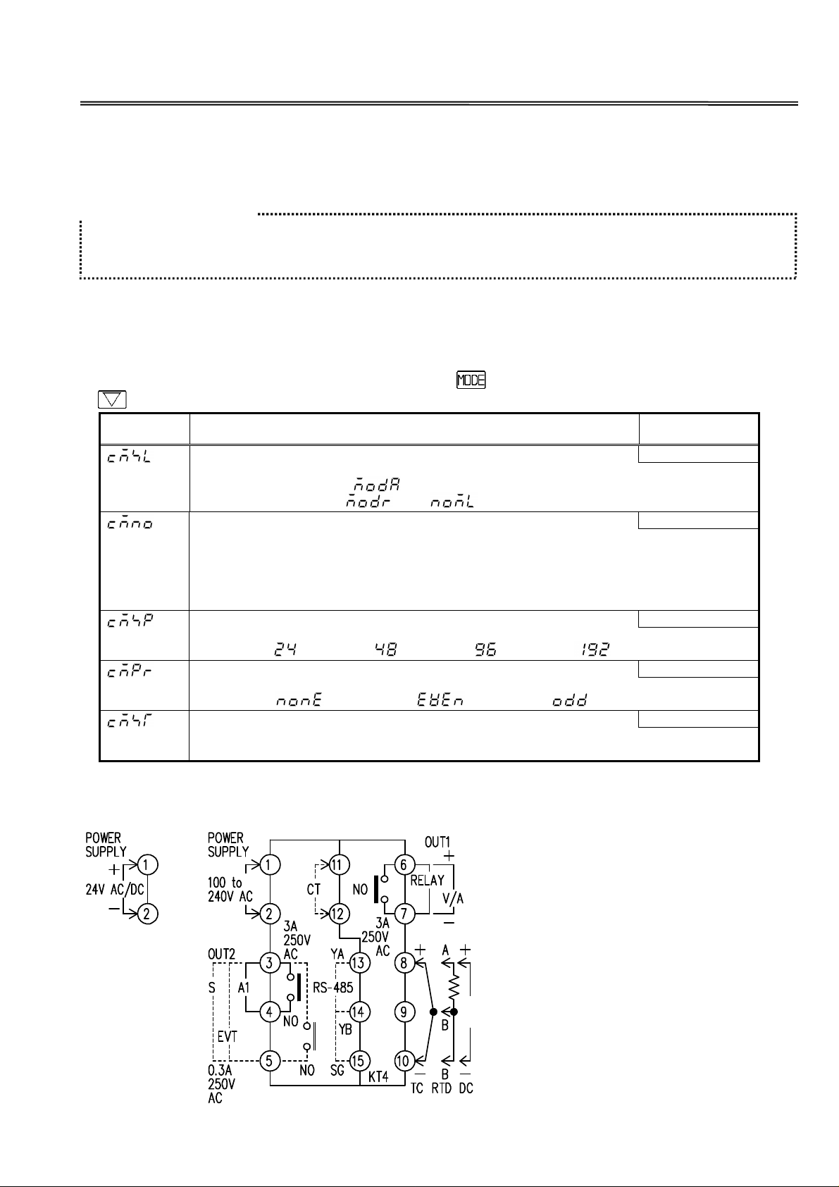
1. Setup of the KT4, KT8 and KT9
Set the items “Communication protocol selection”, “Instrument number setting”, “Communication speed
selection” “Parity selection” and “Stop bit selection” after the “Sensor correction setting” in the Auxiliary
function setting mode 1.
To enter Auxiliary function setting mode 1, press the key for 3 seconds while holding down the
key.
Character
(PV display)
Name, Functions and Setting range
Communication protocol selection ModbusASCII
• Selects the Communication protocol.
• Modbus ASCII mode:
Modbus RTU mode: : Not available.
Instrument number setting 0
• Sets individual instrument number for each unit when communicating by
connecting plural controllers in serial communication.
Up to 31 units can be connected, however, the instrument number can be set
within the range 0 to 95.
• 0 to 95
Communication speed selection 9600bps
• Selects a communication speed to correspond to that of host computer.
• 2400bps: , 4800bps: , 9600bps: , 19200bps:
Parity selection Even
• Selects the parity.
• No parity: , Even parity: , Odd parity:
Stop bit selection 1
• Selects the stop bit.
• 1 or 2
Default
(SV display)
2. Terminal arrangement
2.1 Terminal arrangement of KT4
(Fig. 2.1-1)
OUT1 : Control output 1 (Heating output)
OUT2 : Control output 2 (Cooling output)
RELAY: Relay contact output
V/A : DC voltage output /DC current
output
S : Non-contact relay output
A1 : Alarm 1 output
EVT : Event output (ComprisesA2
output and Heater burnout
alarm output)
CT : Current transformer input
TC : Thermocouple
RTD : Resistance Temperature Detector
DC : DC current or DC voltage
RS-485: Serial communication
1
Page 2
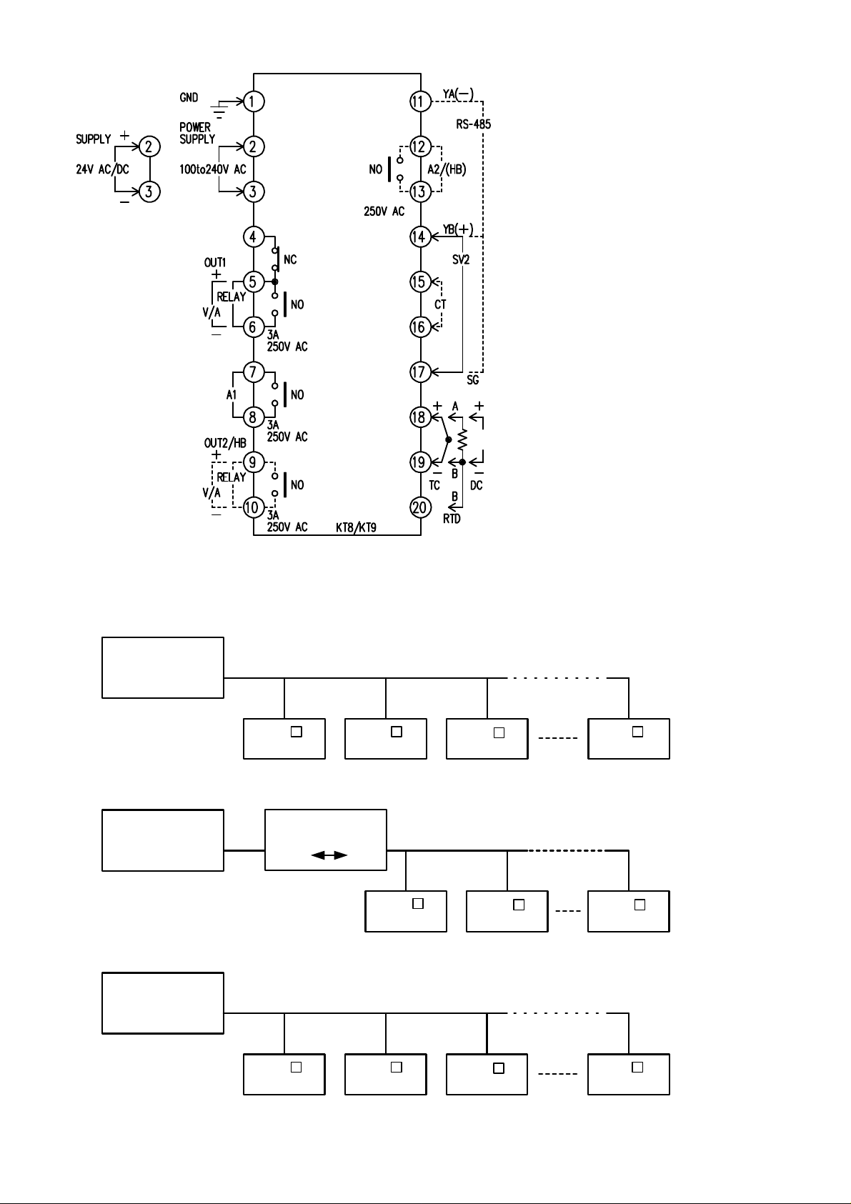
2.2 Terminal arrangement of KT8 and KT9
OUT1 : Control output 1 (Heating output)
OUT2 : Control output 2 (Cooling output)
RELAY: Relay contact output
V/A : Non-contact voltage output /DC
current output
A1 : Alarm 1 output
A2 : Alarm 2 output
HB : Heater burnout alarm output
SV2 : 2nd main setting
CT : Current transformer input
TC : Thermocouple
RTD : Resistance Temperature Detector
DC : DC current or DC voltage
RS-485: Serial communication
(Fig 2.2-1)
3. System configuration
RS-485 multi-drop connection communication
Host computer
RS-485
Host computer
RS-232C
KT
No.0 No.1 No.2
Communication
converter
232C 485
KT
(Fig. 3-1)
KT
No.0
(Fig. 3-2)
RS-485
KT
KT KT
No.1
KT
No.30
No.30
PLC
RS-485
KT
No.0 No.1 No.2
KT
KT
(Fig. 3-3)
2
KT
No.30
Page 3
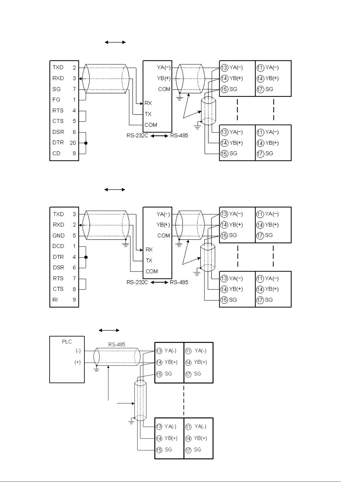
4. Wiring
Shielded
Shielded
Shielded
Shielded
Shielded
When using communication converter (RS-232C)
• Connector: D-sub 25-pin
Connection: RS-232C RS-485 (Communication speed: 2400, 4800, 9600, 19200bps)
Host computer
wire
D-sub 25-pin connector
(Fig. 4-1)
• Connector: D-sub 9-pin
Connection: RS-232C RS-485 (Communication speed: 2400, 4800, 9600, 19200bps)
Host computer
FG
wire
FG
KT4
KT4
KT8, KT9
KT8, KT9
wire
D-sub 9-pin connector
When connecting with PLC (RS-485)
Connection: RS-485 RS-485 (Communication speed: 2400, 4800, 9600, 19200bps)
FG
wire
FG
FG
wire
FG
(Fig. 4-2)
KT4 KT8, KT9
FG
(Fig. 4-3)
3
Page 4
Shielded wire
Connect only one side of the shielded wire to the FG or GND terminal so that current cannot flow to
the shielded wire.
(If both sides of the shielded wire are connected to the FG or GND terminal, the circuit will be closed
between the shielded wire and the ground. As a result, current will run through the shielded wire and
this may cause noise.)
Be sure to ground FG and GND terminals.
Terminator (Terminal resistor)
Do not connect terminator with the communication line because each KT4, KT8 and KT9 has built-in
pull-up and pull-down resistors instead of a terminator.
If there is a large distance between the PLC and the KT4, KT8 and KT9, connect the terminator
(120 or more resistance) on the PLC side.
Setup of the KT4, KT8, KT9
• It is necessary to set the instrument number individually to the KT4, KT8 and KT9 when
communicating by connecting plural units with serial communication.
Select a communication speed of KT4, KT8 and KT9 in accordance with that of the host computer.
• For instrument number setting and communication speed selection, refer to the instruction manual
for KT4, KT8 and KT9.
Memory life of the KT4, KT8, KT9
The memory can contain up to 1,000,000 (one million) set value entries.
This memory life is sufficient when the set value is changed by keypad operation.
However, when changing the set value frequently via the communication function, be careful not to
exceed the 1,000,000 (one million) times limit.
When Lock 1 or Lock 2 is used, every time the set value is changed by the communication function,
the changed value is written in the non-volatile memory.
If the value changed by the communication function is the same as previous one, it is not written in
the non-volatile memory.
When Lock 3 is used and if the set value is changed, the changed value is not written in the
non-volatile memory until the power to the controller is turned off. This has no relation to the limit
for changes in set value.
Therefore, be sure to use Lock 3 when changing the set value frequently via communication.
SV2 of the KT8, KT9
If communication function is applied to KT8 and KT9, SV2 cannot be set by the command.
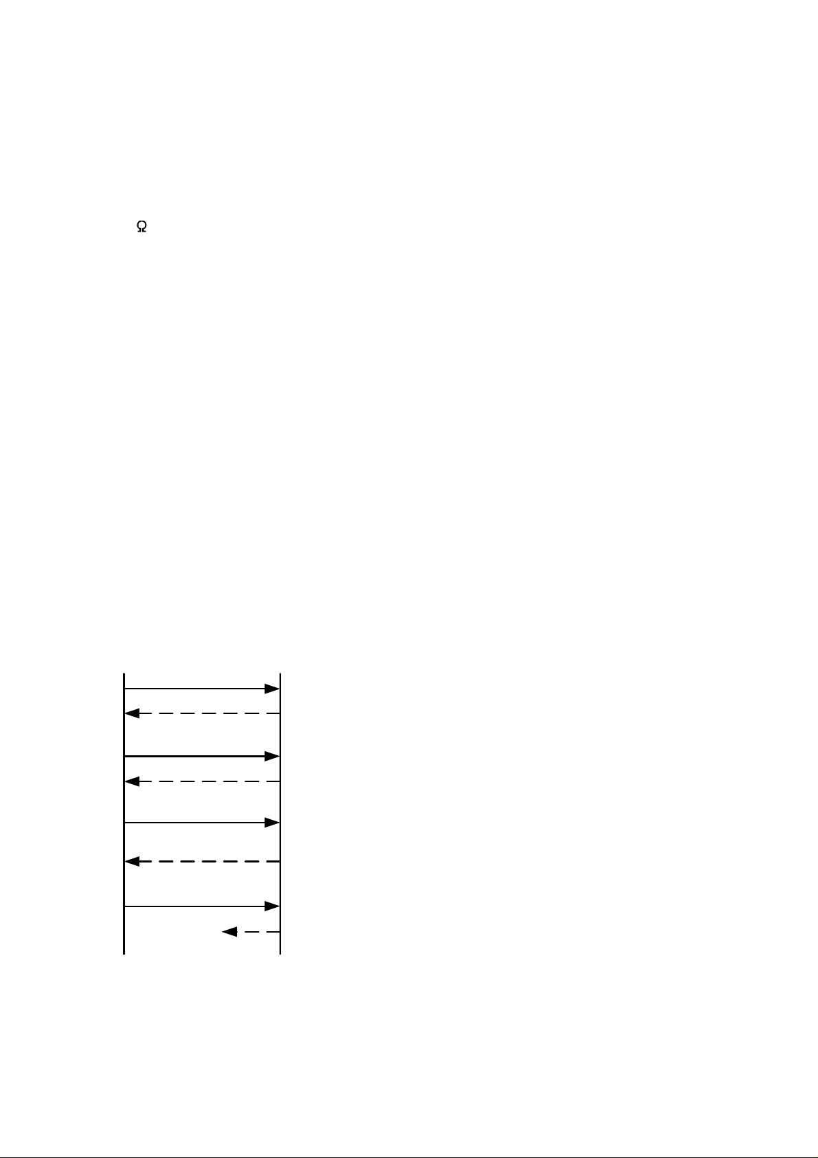
5. Communication procedure
Communication starts with command transmission from the host computer (hereafter Master) and
ends with the response of the KT4, KT8, KT9 (hereafter Slave).
Master Slave
Command
Data
Command
Acknowledgement
Command
Negative
acknowledgement
Command
No response
(Fig.5-1)
• Response with data
When the master sends the reading command, the slave
responds with the corresponding set value or current
action status.
• Acknowledgement
When the master sends setting command, the slave
responds by sending an acknowledgement after the
processing is terminated.
• Negative acknowledgement
When the master sends non-existent command or value
out of the setting range, the slave returns a negative
acknowledgement.
• No response
The slave will not respond to the master when broadcast
address is set, or when there is a communication error
(framing error or parity error), or when LRC or CRC
discrepancy is detected.
Communication timing of the RS-485
Slave side
When a slave starts transmission through the RS-485 communication line, the slave is arranged so
as to provide an idle status (mark status) transmission period of 1 or more characters before
sending the response to ensure the synchronization on the receiving side.
The slave is arranged so as to disconnect the transmitter from the communication line within a
1 character transmission period after sending the response.
4
Page 5

Master side (Notice on setting a program)
Set the program so that the master can disconnect the transmitter from the communication line
within a 1 character transmission period after sending the command in preparation for reception
of the response from the slave.
To avoid the collision of transmissions between the master and the slave, send the next command
after carefully checking that the master received the response.
6. Modbus protocol
6.1 Modbus protocol
Modbus protocol is a communication protocol for the PLC developed by Modicon Inc.
6.2 Transmission mode
There are 2 transmission modes (ASCII and RTU) in Modbus protocol.
6.3 ASCII mode
Hexadecimal (0 to 9,Ato F), which is divided into high order (4-bit) and low order (4-bit) out of
8-bit binary data in command is transmitted as ASCII characters.
Data format Startbit : 1 bit
Data bit : 7 bits
Parity : Even/No/Odd (Selectable)
Stop bit : 1 bit/2 bits (Selectable)
Error detection: LRC (Longitudinal Redundancy Check)
Data interval : 1 second or less
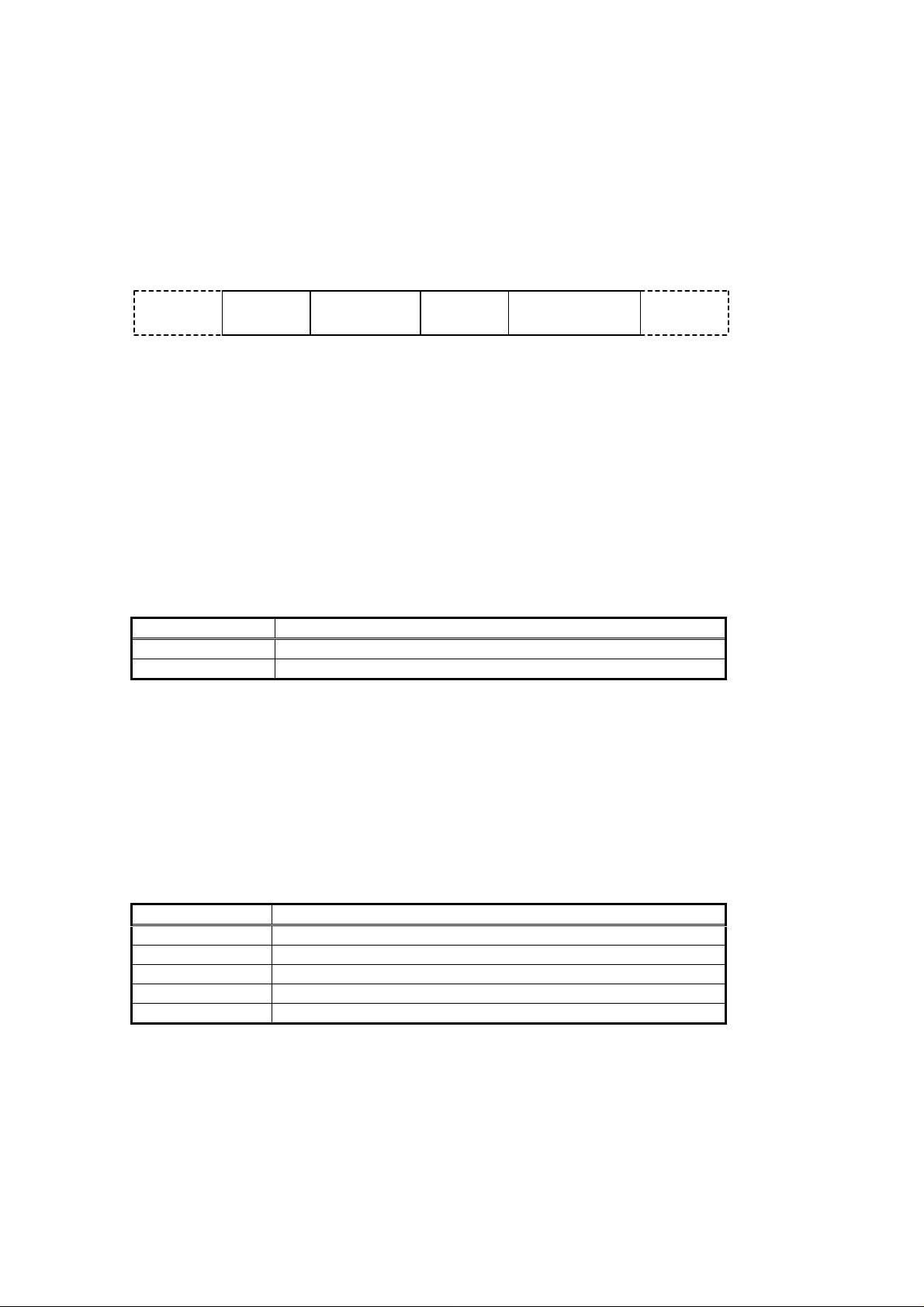
(1) Message configuration
ASCII mode message is configured to start by [: (colon)(3AH)] and end by [CR (carriage return)
(0DH) + LF (Line feed)(0AH)]. (See Fig. 6.3-1)
Header
(:)
(2) Slave address
Slave address is an individual instrument number on the slave side and is set within the range
00H to 5FH (0 to 95).
The master identifies slaves by the slave address of the requested message.
The slave informs the master which slave is responding to the master by placing its own address
in the response message.
[Slave address 00H (broadcast address) can identify all the slaves. However slaves do not respond.]
(3) Function code
Thefunction codeisthecommand code fortheslave to undertake thefollowingaction types (Table 6.3-1).
(Table 6.3-1)
Function code Contents
03 (03H) Reading the set value and information from slaves
06 (06H) Setting to slaves
Function code is used to discern whether the response is normal (acknowledgement) or if any error
(negative acknowledgement) is occurred when the slave returns the response message to the master.
When acknowledgement is returned, the slave simply returns the original function code.
When negative acknowledgement is returned, the MSB of the original function code is set as 1 for
the response.
(For example, when the master sends request message setting 10H to function code by mistake,
slave returns 90H by setting the MSB to 1, because the former is an illegal function.)
For negative acknowledgement, exception code (Table 6.3-2) below is set to the data of response
message and returned to the master in order to inform it that what kind of error has occurred.
Slave
address
Function
code
(Fig. 6.3-1)
Data
Error check
LRC
Delimiter
(CR)
Delimiter
(LF)
(Table 6.3-2)
Exception code Contents
1 (01H) Illegal function (Non-existent function)
2 (02H) Illegal data address (Non-existent data address)
3 (03H) Illegal data value (Value out of the setting range)
17 (11H) Illegal setting (Unsettable status)
18 (12H) Illegal setting (During setting mode by keypad operation, etc)
5
Page 6

(4) Data
Data depends on the function code.
A request message from the master is composed of data item, number of data and setting data.
A response message from the slave is composed of number of bytes, data and exception code
in negative acknowledgement. Effective range of data is –32768 to 32767 (8000H to 7FFFH).
(5) Error check of ASCII mode
After calculating LRC (Longitudinal Redundancy Check) from the slave address to the end of data,
the calculated 8-bit data is converted to two ASCII characters and are appended to the end of
message.
How LRC is calculated
1
Create a message in RTU mode.
2
Add all the values from the slave address to the end of data. This is assumed as X.
3
Make a complement for X (bit reverse). This is assumed as X.
4
Add a value of 1 to X. This is assumed as X.
5
Set X as an LRC to the end of the message.
6
Convert the whole message to ASCII characters.
(6) Message example of ASCII mode
1
Reading (Instrument number 1, SV)
• A request message from the master
Slave
address
(3AH)
1 2 2 4 4 2 2
(30H 31H)
Function
code
(30H 33H)
Data item
(30H 30H 30H 31H) (46H 41H)
Number of
data
(30H 30H 30H 31H)
Error check
LRC
DelimiterHeader
(0DH 0AH)
Number of
characters
(Fig. 6.3-2)
The number of data means the data item to be read, and it is fixed as (30H 30H 30H 31H).
• Response message from the slave in normal status (When SV=100 )
Slave
(3AH)
1 2 2 2 4 2 2
address
(30H 31H)
Function
code
(30H 33H)
Number of
response bytes
(30H 32H)
(30H 30H 36H 34H)
Error check
LRC
(39H 36H) (0DH 0AH)
DelimiterHeader Data
Number of
characters
(Fig.6.3-3)
The number of response bytes means the number of bytes of the data which has been read, and
it is fixed as (30H 32H).
• Response message fromthe slave in exception (error) status (When non-existentdataitem issent)
Slave
address
(3AH)
1 2 2 2 2 2
(30H 31H) (38H 33H)
Function
code
Exception
code
(30H 32H)
(Fig. 6.3-4)
Error check
LRC
(37H 41H)
DelimiterHeader
(0DH 0AH)
Number of
characters
The function code MSB is set to 1 for the response message in exception(error) status (83H).
The exception code (02H: Non-existent data address) is returned.
2
Setting (Instrument number 1, SV=100 )
• A request message from the master
Slave
address
(3AH)
1 2 2 4 4 2 2
(30H 31H)
Function
code
(30H 36H)
Data item
(30H 30H 30H 31H)
Data
(30H 30H 36H 34H)
Error check
LRC
(39H 34H)
DelimiterHeader
(0DH 0AH)
Number of
characters
(Fig. 6.3-5)
• Response message from the slave in normal status
Slave
address
(3AH) (30H 31H) (30H 36H)
1 2 2 4 4 2 2
Function
code
Data item
(30H 30H 30H 31H)(30H 30H 36H 34H) (39H 34H) (0DH 0AH)
Error check
LRC
DelimiterHeader Data
(Fig. 6.3-6)
• Response message from the slave in exception (error)status (When a value out of the setting
range is set.)
Slave
address
(3AH) (30H 31H) (38H 36H) (30H 33H) (37H 36H) (0DH 0AH)
Function
code
Exception
code
(Fig. 6.3-7)
2221
Error check
LRC
2
DelimiterHeader
Number of
2
characters
The function code MSB is set to 1 for the response message in exception (error) status (86H).
The exception code (03H: Value out of the setting range) is returned.
Number of
characters
6
Page 7
6.4 RTU mode
8-bit binary data in command is transmitted as it is.
Data format Start bit : 1 bit
Data bit : 8 bits
Parity : Even/No/Odd (Selectable)
Stop bit : 1 bit/2 bits (Selectable)
Error detection : CRC-16 (Cyclic Redundancy Check)
Data interval : 3.5 characters transmission time or less
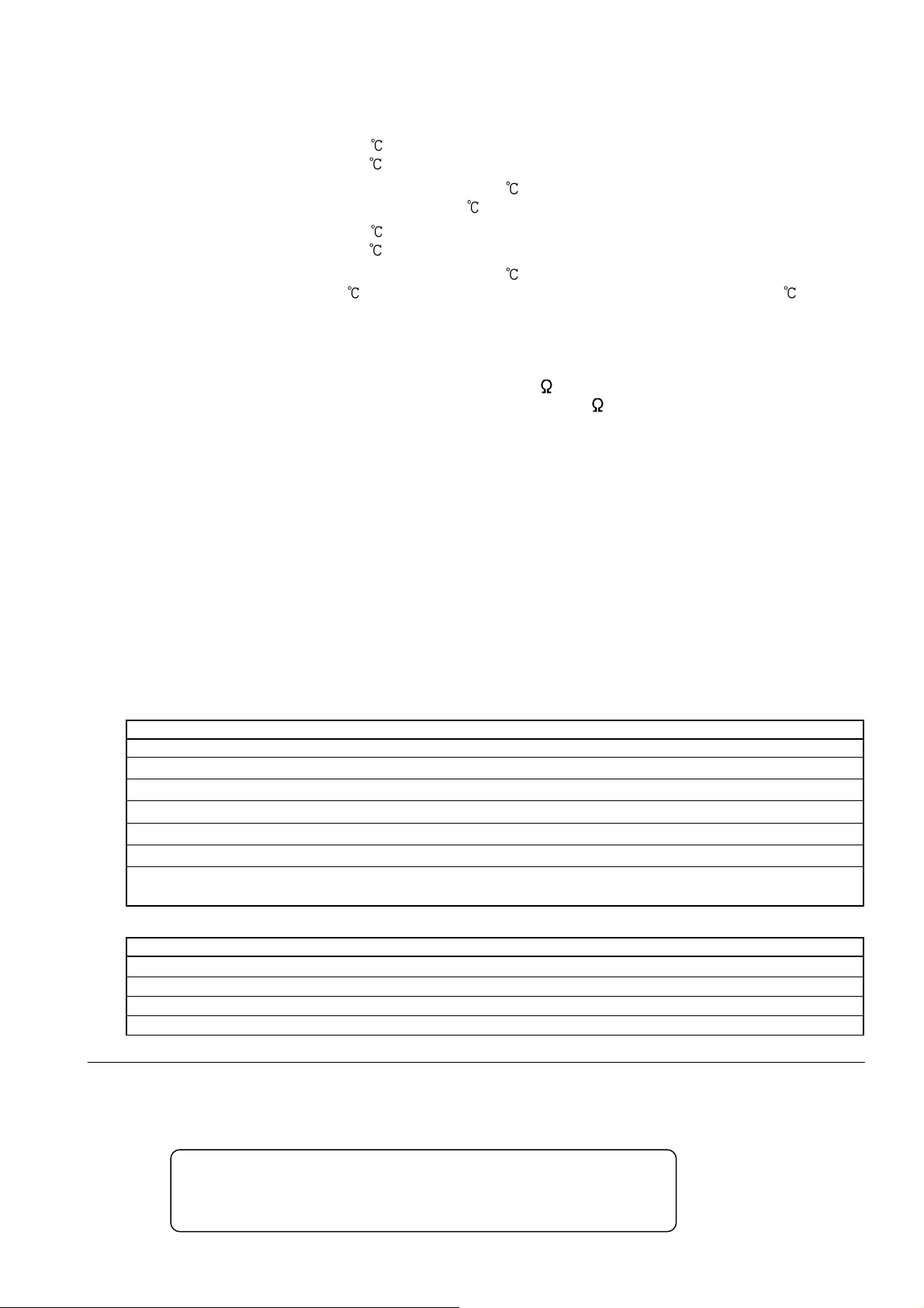
(1) Message configuration
RTU mode is configured to start after idle time is processed for more than 3.5 character transmission
and end after idle time is processed for more than 3.5 character transmission. (See Fig. 6.4-1)
3.5 idle
characters
Slave
address
Function
code
Data
Error check
CRC
3.5 idle
characters
(Fig. 6.4-1)
(2) Slave address
Slave address is an individual instrument number on the slave side and is set within the range
00H to 5FH (0 to 95).
The master identifies slaves by the slave address of the requested message.
The slave informs the master which slave is responding to the master by placing its own address in
the response message.
[Slave address 00H (broadcast address) can identify all the slaves. However slaves do not respond.]
(3) Function code
Thefunction codeis the commandcode forthe slave to undertakethe following action types
(Table6.4-1).
(Table 6.4-1)
Function code Contents
03 (03H) Reading the set value and information from slaves
06 (06H) Setting to slaves
Function code is used to discern whether the response is normal (acknowledgement) or if any error
(negative acknowledgement) is occurred when the slave returns the response message to the master.
When acknowledgement is returned, the slave simply returns the original function code.
When negative acknowledgement is returned, the MSB of the original function code is set as 1 for
the response.
(For example, when the master sends request message setting 10H to function code by mistake,
slave returns 90H by setting the MSB to 1, because the former is an illegal function.)
For negative acknowledgement, exception code (Table 6.4-2) below is set to the data of response
message and returned to the master in order to inform it that what kind of error has occurred.
(Table 6.4-2)
Exception code Contents
1 (01H) Illegal function (Non-existent function)
2 (02H) Illegal data address (Non-existent data address)
3 (03H) Illegal data value (Value out of the setting range)
17 (11H) Illegal setting (Unsettable status)
18 (12H) Illegal setting (During setting mode by keypad operation, etc)
(4) Data
Data depends on the function code.
A request message from the master side is composed of data item, number of data and setting data.
A response message from the slave side is composed of number of bytes, data and exception code
in negative acknowledgement. Effective range of data is –32768 to 32767 (8000H to 7FFFH).
(5) Error check of RTU mode
After calculating CRC-16 (Cyclic Redundancy Check) from the slave address to the end of data, the
calculated 16-bit data is appended to the end of message in sequence from low order to high order.
7
Page 8

How CRC is calculated
characters
characters
characters
characters
characters
characters
In the CRC system, the information is divided by the polynomial series. The remainder is added
to the end of the information and transmitted. The generation of the polynomial series is as follows.
(Generation of the polynomial series: X16+ X15+ X2+ 1)
1
Initialize the CRC-16 data (assumed as X) (FFFFH).
2
Calculate exclusive OR (XOR) with the 1st data and X. This is assumed as X.
3
Shift X one bit to the right. This is assumed as X.
4
When a carry is generated as a result of the shift, XOR is calculated by X of
3
and the fixed
value (A001H). This is assumed as X.
If a carry is not generated, go to step5.
5
Repeat steps
6
XOR is calculated with the next data and X. This is assumed as X.
7
Repeat steps
8
Repeat steps
9
Set X as CRC-16 to the end of message in sequence from low order to high order.
3
3
3
4
and
until shifting 8 times.
to5.
5
to
up to the last data.
(6) Message example of RTU mode
1
Reading (Instrument number 1, SV)
• A request message from the master
3.5 idle
characters
Slave
address
(01H) (03H) (0001H)
1 1 2 2 2
Function
code
Data item
Number of
data
(0001H) (D5CAH)
Error check
CRC
3.5 idle
characters
Number of
(Fig. 6.4-2)
The number of data means the data item to be read, and it is fixed as 0001H.
• Response message from the slave in normal status (When SV=100 )
3.5 idle
characters
Slave
address
(01H) (03H) (02H)
1 1 1 2 2
Function
code
Number of
response bytes
Data
(0064H) (B9AFH)
Error check
CRC
3.5 idle
characters
Number of
(Fig. 6.4-3)
The number of response byte means number of bytes of the data which has been read, and
it is fixed as 02H.
• Response message from the slave in exception (error)status (When non-existent data item is
sent)
3.5 idle
characters
Slave
address
(01H) (83H) (02H) (C0F1H)
1 1 1 2
Function
code
Exception
code
Error check
CRC
3.5 idle
characters
Number of
(Fig. 6.4-4)
The function code MSB is set to 1 for the response message in exception(error) status (83H).
The exception code (02H: Non-existent data address) is returned.
2
Setting (Instrument number 1, SV=100 )
• A request message from the master
3.5 idle
characters
Slave
address
(01H) (06H) (0001H)
1 1 2 2 2
Function
code
Data item
Data
(0064H) (D9E1H)
Error check
CRC
3.5 idle
characters
Number of
(Fig. 6.4-5)
• Response message from the slave in normal status
3.5 idle
characters
Slave
address
(01H) (06H) (0001H)
1 1 2 2 2
Function
code
Data item
Data
(0064H) (D9E1H)
Error check
CRC
3.5 idle
characters
Number of
(Fig. 6.4-6)
• Responsemessagefrom the slave in exception (error)status (When a valueout of the settingrangeis set)
3.5 idle
characters
Slave
address
(01H) (86H) (03H) (0261H)
1 1 1 2
Function
code
Exception
code
Error check
CRC
3.5 idle
characters
Number of
(Fig. 6.4-7)
The function code MSB is set to 1 for the response message in exception(error) status (86H).
The exception code (03H: Value out of the setting range) is returned.
8
Page 9

7. Communication command table
When the data (set value) has a decimal point, remove the decimal point and represent it as a whole
number,then express it in hexadecimal figures.
Modbus
function code
03H/06H 0001H: SV1 Set value
03H/06H 0002H: Not used
03H/06H 0003H: AT/Auto-reset 0000H: Cancel 0001H: Perform
03H/06H 0004H: OUT1 proportional band Set value
03H/06H 0005H: OUT2 proportional band Set value
03H/06H 0006H: Integral time Set value
03H/06H 0007H: Derivative time Set value
03H/06H 0008H: OUT1 proportional cycle Set value
03H/06H 0009H: OUT2 proportional cycle Set value
03H/06H 000AH: Not used
03H/06H 000BH: A1 value Set value
03H/06H 000CH: A2 value Set value
03H/06H 000DH: Not used
03H/06H 000EH: Not used
03H/06H 000FH: HB (Heater burnout alarm) value Set value
03H/06H 0010H: LA (Loop break alarm) time Set value
03H/06H 0011H: LA (Loop break alarm) span Set value
03H/06H 0012H: Set value lock (*1) 0000H: Unlock 0001H: Lock 1
03H/06H 0013H: SV high limit Set value
03H/06H 0014H: SV low limit Set value
03H/06H 0015H: Sensor correction value Set value
03H/06H 0016H: Overlap/Dead band Set value
03H/06H 0017H: Not used
03H/06H 0018H: Scaling high limit Set value
03H/06H 0019H: Scaling low limit Set value
03H/06H 001AH: Decimal point place 0000H: XXXX (No decimal point)
03H/06H 001BH: PV filter time constant Set value
03H/06H 001CH: OUT1 high limit Set value
03H/06H 001DH: OUT1 low limit Set value
03H/06H 001EH: OUT1 ON/OFF action hysteresis Set value
03H/06H 001FH: OUT2 action mode 0000H: Air cooling
03H/06H 0020H: OUT2 high limit Set value
03H/06H 0021H: OUT2 low limit Set value
03H/06H 0022H: OUT2 ON/OFF action hysteresis Set value
03H/06H 0023H: A1 type (*2)
0024H: A2 type (*2)
03H/06H 0025H: A1 hysteresis Set value
03H/06H 0026H: A2 hysteresis Set value
03H/06H 0027H: Not used
03H/06H 0028H: Not used
03H/06H 0029H: A1 action delayed timer Set value
03H/06H 002AH: A2 action delayed timer Set value
Data item Data
0002H: Lock 2 0003H: Lock 3
0001H: XXX.X (1 digit after decimalpoint)
0002H: XX.XX (2 digitsafterdecimal point)
0003H: X.XXX (3 digitsafterdecimal point)
0001H: Oil cooling
0002H: Water cooling
0000H: No alarm action
0001H: High limit alarm
0002H: Low limit alarm
0003H: High/Low limits alarm
0004H: High/Low limit range alarm
0005H: Process high alarm
0006H: Process low alarm
0007H: High limit alarm with standby
0008H: Low limit alarm with standby
0009H: High/Low limits alarm with
standby
9
Page 10

03H/06H 002BH: Not used
03H/06H 0036H: Not used
03H/06H 0037H: OUT/OFF 0000H: OUT 0001H: OFF
03H/06H 0038H: Auto/Manual control 0000H: Automatic control
0001H: Manual control
03H/06H 0039H: Manual control MV (manipulated
variable)
03H/06H 003AH: Not used
03H/06H 003FH: Not used
03H/06H 0040H: A1 action Energized/Deenergized 0000H: Energized
03H/06H 0041H: A2 action Energized/Deenergized 0000H: Energized
03H/06H 0042H: Not used
03H/06H 0043H: Not used
03H/06H 0044H: Input type 0000H: K [–200 to 1370 ]
03H/06H 0045H: Direct/Reverse action 0000H: Heating (Reverse action)
03H/06H 0046H: Not used
03H/06H 0047H: AT bias Set value
03H/06H 0048H: ARW (anti-reset windup) Set value
03H/06H 006FH: Key Lock 0000H: Key enabled 0001H:Key Lock
06H 0070H: Key operation change flag clearing 0000H:No action 0001H: All clearing
03H 0080H: PV reading Present PV (input value)
03H 0081H: OUT1 MV reading Present MV (manipulated variable)
03H 0082H: OUT2 MV reading Present MV (manipulated variable)
Set value
0001H: Deenergized
0001H: Deenergized
0001H: K [–199.9 to 400.0 ]
0002H: J [–200 to 1000 ]
0003H: R [0 to 1760 ]
0004H: S [0 to 1760 ]
0005H: B [0 to 1820 ]
0006H: E [–200 to 800 ]
0007H: T [–199.9 to 400.0 ]
0008H: N [–200 to 1300 ]
0009H: PL- [0 to 1390 ]
000AH: C (W/Re5-26) [0 to 2315 ]
000BH: Pt100 [–199.9 to 850.0 ]
000CH: JPt100 [–199.9 to 500.0 ]
000DH: Pt100 [–200 to 850 ]
000EH: JPt100 [–200 to 500 ]
000FH: K [–320 to 2500 ]
0010H: K [–199.9 to 750.0 ]
0011H: J [–320 to 1800 ]
0012H: R [0 to 3200 ]
0013H: S [0 to 3200 ]
0014H: B [0 to 3300 ]
0015H: E [–320 to 1500 ]
0016H: T [–199.9 to 750.0 ]
0017H: N [–320 to 2300 ]
0018H: PL- [0 to 2500 ]
0019H: C (W/Re5-26) [0 to 4200 ]
001AH: Pt100 [–199.9 to 999.9 ]
001BH: JPt100 [–199.9 to 900.0 ]
001CH: Pt100 [–300 to 1500 ]
001DH: JPt100 [–300 to 900 ]
001EH: 4 to 20mA DC [–1999 to 9999]
001FH: 0 to 20mA DC [–1999 to 9999]
0020H: 0 to 1V DC [–1999 to 9999]
0021H: 0 to 5V DC [–1999 to 9999]
0022H: 1 to 5V DC [–1999 to 9999]
0023H: 0 to 10V DC [–1999 to 9999]
0001H: Cooling (Direct action)
10
Page 11

03H 0083H: Not used
03H 0084H: Not used
03H 0085H: OUT status reading
03H 0086H: Not used
03H 0087H: Not used
03H 00A0H: Not used
03H 00A1H: Instrument information reading
0000 0000 0000 0000
15
2
to 2
0
20digit: OUT1
0: OFF 1: ON
21digit: OUT2
0: OFF 1: ON
22digit: A1 output
0: OFF 1: ON
23digit: A2 output
0: OFF 1: ON
24digit: Not used (Always 0)
25digit: Not used (Always 0)
26digit: HB (Heater burnout alarm)
output
0: OFF 1: ON
(When sensor burnout, 0: OFF)
27digit: LA (Loop break alarm) output
0: OFF 1: ON
28digit: Overscale
0: OFF 1: ON
29digit: Underscale
0: OFF 1: ON
210digit: OUT/OFF selection
0: OUT 1: OFF
211digit: AT/Auto-reset
0: OFF 1: ON
212digit: OUT/OFF keyfunction selection
0: OUT/OFF
1: Auto/Manual
213digit: Not used (Always 0)
214digit: Auto/Manual control
0: Automatic
1: Manual
215digit: Key operation change
0: No 1: Yes
0000 0000 0000 0000
15
2
to 2
0
20digit: Not used (Always 0)
21digit: Cooling action
0: Not applied 1: Applied
22digit: A1 function
0: Not applied 1: Applied
23digit: A2 function
0: Not applied 1: Applied
24digit: Not used (Always 0)
25digit: Not used (Always 0)
26digit: HB (Heater burnout alarm)
0: Not applied 1: Applied
27digit: LA (Loop break alarm)
0: Not applied 1: Applied
28to 215digit: Not used (Always 0)
(*1) When Lock 3 is designated, the set data is not saved in the memory.
This is why the set value reverts to the one before Lock 3 when power is turned OFF.
(*2) When alarm type is changed, the alarm set value reverts to the default value and
alarm output status is also initialized.
11
Page 12
Notice
When data setting is changed by front keypad operation, the data that is related to the changed
item is also changed automatically as shown in Example 1 below.
However, when the data setting is changed by communication function, the related data does not
change as shown in Example 2 below. (Only the changed data is altered.)
(Example 1) SV high limit: 1370
SV : 1000
When SV high limit is changed to 800 by the front keypad operation, both SV high
limit and SV are changed to 800 .
(Example 2) SV high limit: 1370
SV : 1000
When SV high limit is changed to 800 by communication function, SV high limit is
changed to 800 , however, SV is maintained at the same temperature 1000 .
7. Specifications
Communication method : Half-duplex
Cable length : Maximum communication distance 1000m
Cable resistance: Within 50 (Terminator is not necessary or
120 or more on PLC side.)
Communication line : EIA RS-485
Connectable number of units: Maximum 31 units to 1 host computer
Communication speed : 2400, 4800, 9600, 19200bps (Selectable by keypad operation)
Synchronous system : Start-stop synchronous
Code form :ASCII, binary
Error detection : Parity check, Checksum (LRC, CRC)
Error correction : Command request repeat system
Data format Startbit : 1
Data bit : 7, 8
Parity : Even, Odd, No parity
Stop bit : 1
8. Troubleshooting
If any malfunctions occur, refer to the following items after checking the power supply to the master
and the slave.
• Problem: Communication failure
Check the following
The connection or wiring of communication is not secure.
Burnout or imperfect contact on the communication cable and the connector.
Communication speed of the slave does not coincide with that of the master.
The data bit, parity and stop bit of the master do not accord with those of the slave.
The instrument number of the slave does not coincide with that of the command.
The instrument numbers are duplicated in multiple slaves.
When communicating without using communication converter, make sure that the program is
appropriate for the transmission timing.
• Problem: Although communication is occurring, the response is 'exception code'.
Check the following
Check that a non-existent command code has not been sent.
The setting command data exceeds the setting range of the slave.
The controller cannot be set when functions such asAT is performing.
The operation mode is under the front keypad operation setting mode.
For further inquiries, please consult our agency or the shop where you purchased the unit.
Panasonic Electric Works Co., Ltd. Automation Controls Business Unit
Head Office: 1048 Kadoma, Kadoma-shi, Osaka 571-8686, Japan
Telephone : Japan (81) Osaka (06) 6908-1050
Facsimile : Japan (81) Osaka (06) 6908-5781
Pursuant to the directive 2004/108/EC, article 9(2)
Panasonic Electric Works Europe AG
Rudolf-Diesel-Ring 2 83607 Holzkirchen, Germany
This product has been developed / produced for industrial use only.
12
 Loading...