

Panasonic KT7 Installation Manual

Instruction manual Temperature Controller KT7
To prevent accidents arising from the misuse of this controller, please ensure the operator using it
receives this manual.
SAFETY PRECAUTIONS
Be sure to read these precautions before using our products.
The safety precautions are classified into categories: “Warning” and “Caution”.
Warning : Procedures which may lead to dangerous conditions and cause death or serious injury,
if not
carried out properly.
Caution : Procedures which may lead to dangerous conditions and cause superficial to medium injury
or physical damage or may degrade or damage the product, if not carried out properly.
Warning
• When using this controller on occasions which serious injury would be expected to occur or when damage
is likely to expand or proliferate, make sure to take safety measures such as installing double safety
structures.
• Do not use this controller in an environment with flammable gases, or it may cause explosion.
Caution
• Fasten the electric wire with the terminal screws securely. Imperfect connection may cause abnormal
heating or fumes.
• Use this controller according to the rating and environmental conditions. Otherwise abnormal heating or
fumes may occur.
• Do not touch the terminals while the power is supplied to the controller, as this may cause electric shock.
• Do not disassemble or modify the controller, as this may cause electric shock or fumes.
Caution
• This instrument should be used according to the specifications described in this manual.
If it is not used according to the specifications, it may malfunction or cause fire.
• Be sure to follow the warnings, cautions and notice. If not, it could cause serious injury or accidents.
• The contents of this instruction manual are subject to change without notice.
• This instrument is designed to be installed in a control panel. If not, measures must be taken to ensure
that the operator cannot touch power terminals or other high voltage sections.
• Be sure to turn the power supplied to the instrument OFF before cleaning this instrument.
• Use a soft, dry cloth when cleaning the instrument.
(If paint thinner is used, it might deform or tarnish the unit.)
• As the display section is vulnerable, do not strike or scratch it with a hard object.
• Any unauthorized transfer or copying of this document, in part or in whole, is prohibited.
• Tatsuno Matsushita Electric Works, Ltd. is not liable for any damages or secondary damages incurred as
a result of using this product, including any indirect damages.
1. Model number
1.1 Explanation of model number
A K T 7 1 1 0
(1) (2) (3) (4) (5)
(1) Supply voltage ---------------------- 1: 100 to 240V AC, 2: 24V AC/DC
(2) Input type ----------------------------- 1: Multi-input (Thermocouple, RTD, DC current and DC voltage
can be selected by key operation)
(3) Control output (OUT) -------------- 1: Relay contact, 2: Non-contact voltage, 3: DC current
(4) Alarm output ------------------------- 1: Alarm output (1 point)
(The alarm action and Energized /Deenergized can be selected
by key operation)
(5) Heater burnout alarm ------------- 0: Not available, 1: Available (5A), 2: Available (10A), 3:
Available
(20A), 4: Available (50A)
(Heater burnout alarm is not available for the DC current output)

1.2 How to indicate the rated label
The rated label is put on the case.
When Heater burnout alarm is added, CT rated current is written in the bracket.
(1)
(2)
(1) Model number, supply voltage, input type, output type, etc. are entered.
(2) Lot number is entered.
A K T 7 1 1 1 1 0 0
No.
(e.g.)
Supply voltage: 100 to 240V AC
Multi-input
Relay contact output
Alarm output (1 point)
Heater burnout alarm is not added
2. Name and functions of the sections
(1) EVT indicator
A red LED lights up when Event output [Alarm, Loop break alarm
or Heater burnout alarm (Option)] is ON.
(2) OUT indicator
When OUT output is ON, a green LED lights up.
For DC current output type, this blinks corresponding to the output
manipulated variable.
(3) AT indicator
A yellow LED blinks while PID auto-tuning is being performed.
(4) PV display
Indicates the input value (PV) with a Red LED.
(5) SV display
Indicates the setting value (SV) with a Green LED.
(6) Increase key
Increases the numeric value.
(7) Decrease key
Decreases the numeric value.
(8) Mode key
Selects the setting mode or registers the setting value
(By pressing the Mode key, the setting value can be registered)
(9) Sub mode key
Brings up Auxiliary function setting mode 2 with the Mode key. (Fig. 2-1)
.
(1)
(2)
(4)
(5)
(6)
(7)
(3)
(8)
(9)
Notice
When setting the specifications and functions of this controller, connect the terminals 1 and 2 for power
source first, then set them referring to “5. Setup” before performing “3. Mounting to control panel” and
“4. Wiring connection”.
3. Mounting to control panel
3.1 Site selection This instrument is intended to be used under the following environmental conditions (IEC61010-1): Overvoltage category
Mount the controller in a place with:
• A minimum of dust, and an absence of corrosive gases
• No flammable, explosive gasses
• Few mechanical vibrations or shocks
• No exposure to direct sunlight, an ambient temperature of 0 to 50 (32 to 122 )
that does not change rapidly
• An ambient non-condensing humidity of 35 to 85%RH
• No large capacity electromagnetic switches or cables through which large current is flowing
• No water, oil or chemicals or where the vapors of these substances can come into direct
, Pollution degree 2

contact with the controller

3.2 External dimension
(Fig. 3.2-1)
3.3 CT (Current transformer) external dimension
22.5
75
97
100
AKT4815 (for 20A) AKT4816 (for 50A)
(Fig. 3.3-1)
3.4 Mounting to DIN rail
Caution
Mount the DIN rail horizontally.
When DIN rail is mounted vertically, be sure to use commercially available fastening plates at the end of
KT7 series. Mount the KT7 series to the DIN rail so that the KT7 series cannot move.
However, if the DIN rail is mounted horizontally in a position susceptible to vibration or shock, the
fastening plates must be used as well.
Recommended fastening plate
Matsushita electric works, LTD. Fastening plate ATA4806

(1) Hook (1) of KT7 series on the upper side of the DIN rail. (Fig. 3.4-1)
(2) Making the (1) part of the KT7 series as a support, fit the lower part of the KT7 series to the DIN rail.
KT7 series will be completely fixed to DIN rail with a “Click” sound. (Fig. 3.4-1)
(Fig. 3.4-1)
(2)
(1)
4. Wiring connection
Warning
Turn the power supplied to the instrument OFF before wiring or checking it.
Working or touching the terminal with the power switched ON may result in Electric Shock
causing severe injury or death.
Caution
• Do not leave wire chips in the KT7 series when wiring, because they could cause fire, malfunction and
trouble.
• Insert the connecting cable into the designated connector securely. Otherwise malfunction due to
imperfect contact may occur.
• Connect the AC power wire to the designated terminal as is written in this instruction manual, otherwise
it may burn and damage the KT7 series.
• Tighten the terminal screw with the specified torque. If not, it may damage the terminal screw and deform
the case.
• Use thermocouple and compensating lead wire that fit sensor input specification of this unit.
• Use the 3-wire RTD that corresponds to the sensor input specification of this unit.
• When using DC voltage and current input types, do not confuse the polarity when wiring.
• When using a 24V AC/DC for the power source, do not confuse the polarity when it is DC.
• Keep input wires (Thermocouple, RTD, etc) away from power source and load wires to avoid external
interference.
• To prevent the unit from harmful effects of the unexpected level noise, it is recommended that a surge
absorber be installed between the electromagnetic switch coils.
• This unit does not have built-in power switch, circuit breaker or fuse. Therfore, it is necessary to install
them in the circuit near the external unit.
(Recommended fuse: Time-lag fuse, rated voltage 250V ACrated current 2A)
Note
Tighten the terminal screw properly referring to the table below.
Terminal screw Terminal No. Torque
M2.6 1 to 4 Max. 0.5Nem
M2.0 5 to 9 Max. 0.25Nem
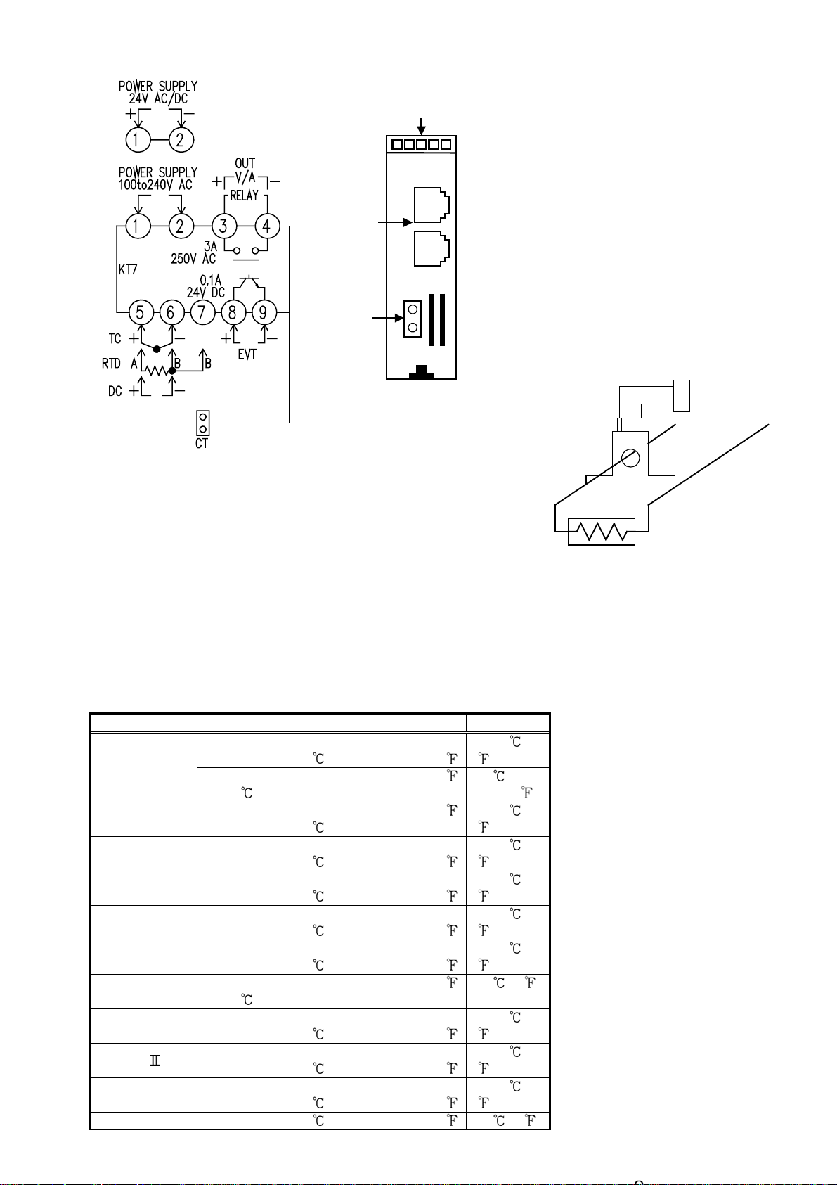
Terminal arrangement
p
Lower part of main body
• OUT : Control output
• RELAY: Relay contact output
• V/A : DC voltage output/ DC current
output
• EVT : Event output (Activates when
Alarm, Loop break alarm or
Heater burnout alarm [option]
is ON)
• TC : Thermocouple
• RTD : Resistance temperature detector
• DC : DC current or DC voltage
CT in
ut
CT input socket
(Fig. 4-1)
Option: Heater burnout alarm
CT
Power
supply
This alarm is not available for detecting current under phase control.
Use the current transformer (CT) provided, and pass
a lead wire of the heater circuit into a hole of the CT.
When wiring, keep the CT wire away from AC sources
or load wires to avoid the external interference. (Fig. 4-2)
5. Setup
Heater
Wire the power terminals only. After the power is turned on, the sensor input characters and temperature
unit are indicated on the PV display and the input range high limit value is indicated on the SV display for
approx. 3 seconds (Table 5-1).
(If any other value is set in the scaling high limit value, it is indicated on the SV display.)
During this time all outputs and the LED indicators are in OFF status.
Control will then start and the input value will be indicated on the PV display and setting value will be
indicated on the SV display.
(Table 5-1)
Input type Input range Resolution
–320 to 2500
–199.9 to 750.0
–320 to1800
0 to
3200
0 to
3200
0 to
3300
–320 to 1500
–199.9 to 750.0
–320 to 2300
0 to
2500
0 to
4200
1
)
(
0.1
(
)
1
)
(
1
)
(
1
)
(
1
)
(
1
)
(
0.1 ( )
1
)
(
1
)
(
1
)
(
K
J
R
S
B
E
T
N
PL-
C(W/Re5-26)
–200 to 1370
–199.9 to
400.0
–200 to1000
0 to
1760
0 to
1760
0 to
1820
–200 to 800
–199.9 to
400.0
–200 to 1300
0 to
1390
0 to
2315
Pt100 –199.9 to 850.0 –199.9 to 999.9 0.1 ()
*1: Input range and
decimal point place
can be changed.
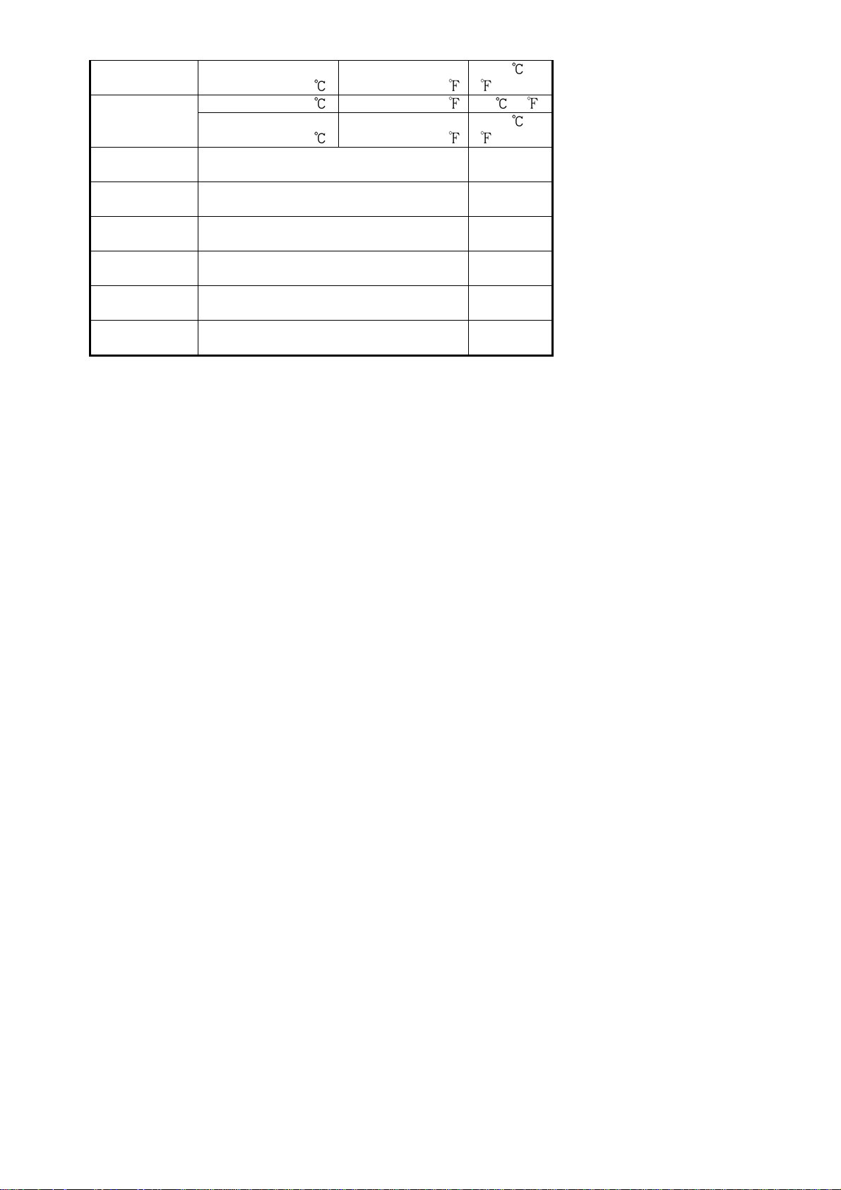
JPt100
4 to 20mA DC
0 to 20mA DC
0 to 1V DC
0 to 5V DC
1 to 5V DC
0 to 10V DC
–200 to 850
–199.9 to 500.0 –199.9 to 900.0 0.1 ( )
–200 to 500
–1999 to 9999
*1,*2
–1999 to 9999
*1,*2
–1999 to 9999
*1
–1999 to 9999
*1
–1999 to 9999
*1
–1999 to 9999
*1
–300 to 1500
–300 to 900
1
)
(
1
)
(
1
1
1
1
1
1

5.1 Setup flow chart
PV/SV display mode
(Approx. 3s)
Output manipulated
variable indication
(Approx. 3s)
[Sub setting mode] [Auxiliary function [Auxiliary function
[Main setting mode]
setting mode 1] setting mode 2]
SV
[
]
OUT proportional band setting
Integral time setting
Derivative time setting
ARW setting
OUT proportional cycle setting
Manual reset setting
Alarm setting
Heater burnout alarm setting
Loop break alarm action time
Loop break alarm action span
(Approx. 3s)
AT setting
[ ]
]
[
[ ]
[
]
]
[
]
[
[
[
[
setting [
setting [
]
]
]
]
]
Setting value lock
selection [ ]
Sensor correction setting
[ ]
Scaling low limit setting
Decimal point place selection
PV filter time constant setting
OUT high limit setting
OUT low limit setting
Control output ON/OFF action
Alarm action selection
Alarm action Energized/
Alarm HOLD function selection
Input type selection
[ ]
Scaling high limit setting
[ ]
[ ]
[ ]
[ ]
[ ]
[ ]
hysteresis setting [ ]
[ ]
Deenergized selection [ ]
[ ]
Alarm hysteresis setting
Alarm action delayed timer
Controller/Converter function
selection [
[
setting [
Direct/Reverse action selection
]
[ ]
]
]
 Loading...