

Page 1
Communication Installation Instructions KT4H/B TemperatureController
Negative
[17]
[19]
[20]
[21]
[22]
[23]
[24]
Shielded
Shie
lded
Shielded
Shielded
These instructions are for communication functions. For detailed operating
instructions, please refer to User’s Manual for the KT4H/B.
Serial communication and Toolport communication cannot be used together.
When performing Serial communication, remove the tool cable (AKT4H820) from
the USB port of the PC and tool connector of the KT4H/B.
When performing Tool port communication,it is not required to remove the Serial
communication cables. However,do not send a command from the master side.
No. KT4HCE4 2009.11
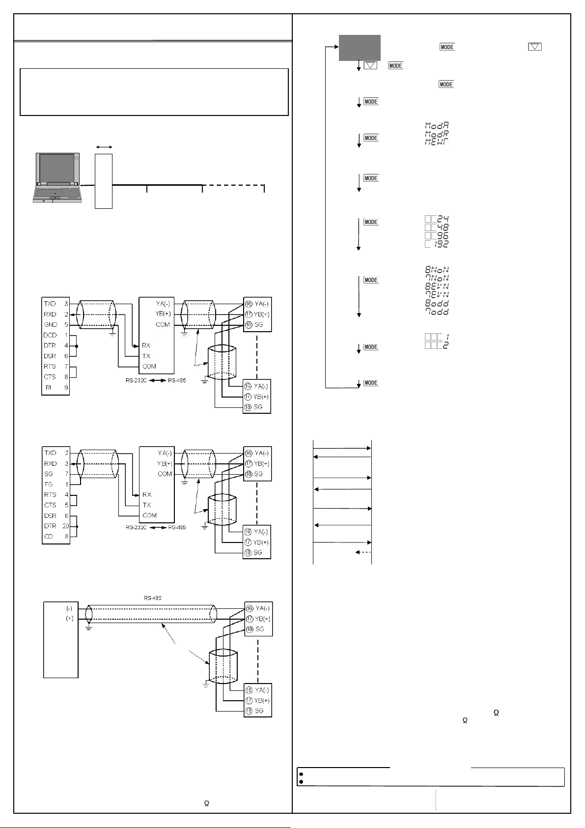
5. System configuration
Communicationconverter
RS-232C RS-485
No. 1 No. 2 No. 31
Host computer
(Fig. 1-1)
KT4H or KT4B
2. Wiring
Wiring example using a communication converter
Using a D-sub 9-pin Connector
Host computer
wire
FG
D-sub 9-pin connector
Using a D-sub 25-pin Connector
Hostcomputer
wire
D-sub 25-pin connector
When connecting to a PLC (RS-485)
PLC
FG
Shieldedwire
Connectonlyone sideoftheshieldedwire to the FG terminalsothatcurrentcannot
flowto the shielded wire.If both sidesofthe shielded wire are connected to the FG
terminal, the circuit will be closedbetween the shielded wire and the ground. As a
result, current will run through the shielded wire and this may cause noise.Be sure
togroundthe FG terminal.
Terminator(Terminal resistor)
Do not connect terminator with the communicationline because each KT4H/B has
built-inpull-upandpull-downresistorsinsteadof aterminator.
If there is a large distance between the PLC and the KT4H/B, connect the
terminator on the PLC side.(Connecta terminatorof120 ormoreresistance.)
(Fig. 2-1)
(Fig. 2-2)
(Fig. 2-3)
FG
wire
FG
FG
wire
FG
Shielded wire
FG
KT4H or KT4B
KT4H or KT4B
KT4H or KT4B
3. Communication parameter setting
Set each communication parameter following the procedures below.
(1)
(2)
(3)
(4)
(5)
(6)
(7)
(8)
Numbers such as [17], [19], etc. are setting item numbers.
Refer to the User’s Manual for the KT4H/B.
+
(Twice)
Proceed to Auxiliary function setting mode.
Press key while pressing key in
the PV/SV display mode. The unit proceeds
to Auxiliary function setting mode.
Auxiliary function setting mode
Press key twice.
The unit proceeds to Communication protocol
selection.
Communication protocol selection
Select the communication protocol.
Instrument number setting
Set the instrument number of the controller
individually when communicating by connecting
plural instruments.
Communication speed selection
Set the communication speed equal to that of
the host computer.
Data bit/Parity selection
Select the data bit and parity.
Stop bit selection
Select the stop bit.
Communication response time setting
Set the minimum response time.
5 to 99 (Default: 5ms)
: Modbus ASCII mode (Default)
: Modbus RTU mode
: MEWTOCOL (Slave)
1 to 99 (Default: 1)
: 2400bps
: 4800bps
: 9600bps (Default)
: 19200bps
: 8 bits/No parity
: 7 bits/No parity
: 8 bits/Even
: 7 bits/Even (Default)
: 8 bits/Odd
: 7 bits/Odd
: 1 (Default)
: 2
4. Communication procedures
Communication starts with command transmission from the host computer
(Master) and ends with the response of the KT4H/B (Slave).
Master Slave
Command
Data
Command
Acknowledgement
Command
Acknowledgement
Command
Noresponse
(Fig.4-1)
RS-485 communication timing
Master side (Notice on programming)
Set the program so that the master can disconnect the transmitter from the
communication line within a 1 character transmissionperiod after sending the
command in preparation for reception of the response from the slave.
To avoid the collision of transmissions between the master and the slave, send
thenextcommand aftercarefullychecking thatthemasterreceivedthe response.
Slave side
When the slave starts transmission through the communication line, the slave
is arranged so as to provide an idle status(mark status)transmission period of
5ms or more (communication response time from 5 to 99ms settable) before
sending the response to ensure the synchronization on the receiving side.
Theslaveis arrangedso as todisconnect the transmitterfrom thecommunication
line within a 1 character transmission period after sending the response.
• Response with data
When the master sends the reading command, the
slave responds with the corresponding set value or
current status.
• Acknowledgement
When the master sends the setting command, the
slave responds by sending the acknowledgement
after the processing is terminated.
• Negative acknowledgement
When the master sends non-existent command or
value out of the setting range, the slave returns the
negative acknowledgement.
• No response
Theslavewillnotrespondtothemasterinthefollowing cases.
• Global address “FF” (MEWTOCOL) is set.
• Broadcast address (Modbus protocol) is set.
• Communication error (framing error,parity error)
• LRC discrepancy (Modbus ASCII mode)
• CRC-16 discrepancy (Modbus RTU mode)
5. Specifications
Communicationsystem: Half duplex
Cable length : 1,000m (Max.), cable resistance 50 or less
Communicationline :EIARS-485
Communicationspeed : 9600bps(2400,4800,9600,19200bps) Selectablebykey
Synchronoussystem :Start-stopsynchronous
Code :ASCII(ModbusASCII,MEWTOCOL),Binary(ModbusRTU)
Errorcorrection :Commandrequestrepeatsystem
PleasedownloadUser’sManualathttp://panasonic-denko.co.jp/ac/e/
ForthedetailedusageandUser’sManual,pleasecontactusat theaddressbelow.
Panasonic E lectric Works Co., Ltd. Automation Controls Business U nit
HeadOffice:1048Kadoma,Kadoma-shi,Osaka571-8686,Japan Panasonic Electric Works Europe AG
Telephone: Japan (81) Osaka (06) 6908-1050 Rudolf-Diesel-Ring 2 83607 Holzkirchen, Germany
Facsimile : Japan (81) Osaka (06) 6908-5781 Thisproducthasbeendeveloped/producedfor industrialuseonly.
(Terminator: None or 120 or more on PLC side)
AboutUser’sManual
Pursuant to the directive 2004/108/EC, article 9(2)
Page 2
EVT1
: Alarm 1 output
6.
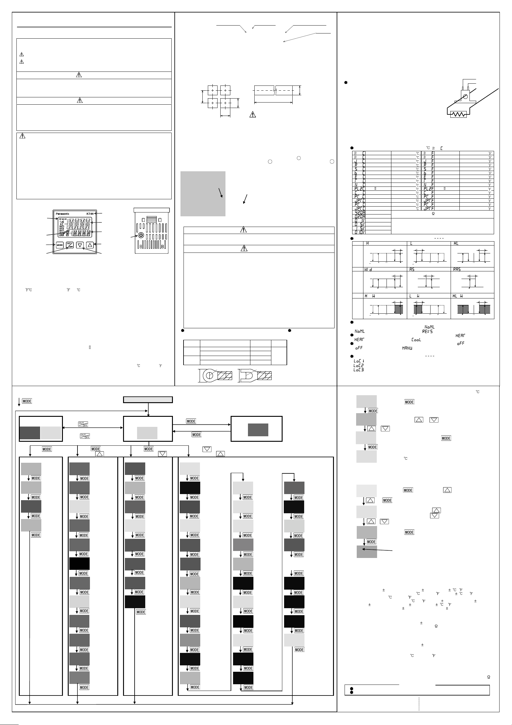
Basic operation
InstallationInstructions KT4H/B TemperatureController
contact with the controller
Forapprox.3secondsafterthepoweristurnedon,thePVdisplayindicatesthe
indicates input range high limit value (TC, RTD
Action indicators
Tool connector
(Fig. 3-4
)
Thismeansthatif MODEkeyispressed,
(Fig. 3-1)
[1]
[2]
[3]
[4]
[5]
[6]
[7]
[8]
[9]
[10]
[11]
[12]
[13]
[14]
[15]
[16]
[17]
[18][19]
[20]
[21]
[22]
[23]
[24]
[25]
[26]
[27]
[28]
[29]
[30]
[31]
[32]
[33]
[34]
[35]
[36]
[37]
[38]
[39]
[40]
[41]
[42]
[43]
[44]
[45]
[46]
[47]
[48]
[49]
[50]
[51]
[52]
[53]
[54]
[55]
[56]
Press keyforapprox.3sec.
Rubber gasket
Model
To ensure safeand correctuse,thoroughlyreadandunderstandthese instructionsbeforeusing
thisinstrument.Fordetailedusageandoptions,pleaserefertoUser’sManualfortheKT4H/B.
SAFETY PRECAUTIONS
(Besuretofollowtheprecautionsdescribedbelowtopreventinjuryoraccidents.)
Thesafetyprecautionsareclassifiedintocategories:“Warning”and“Caution”.
Warning:Procedures whichmayleadto dangerousconditionsand causedeathor
seriousinjury,if notcarriedoutproperly.
Caution:Procedureswhichmayleadtodangerousconditionsandcausesuperficial
to medium injury or physical damage or may degrade or damage the
product,ifnotcarriedoutproperly.
• When using this controller on occasions which serious injury would be expected to
occur or when damage is likely to expand or proliferate, make sure to take safety
measuressuchasinstallingdoublesafetystructures.
• Do not use this controllerin an environment with flammable gases, or it may cause
explosion.
Warning
No. KT4HE5 2009.07
Caution
•Fasten the electric wire withthe terminalscrews securely. Imperfectconnectionmay
causeabnormalheatingorfumes.
• Use this controller according to the rating and environmental conditions. Otherwise
abnormalheatingorfumesmay occur.
• Do not touch the terminals while the power is supplied to the controller, as thismay
causeelectricshock.
•Do notdisassembleor modifythecontroller, asthismaycauseelectricshockorfumes.
Caution
• This instrument should be used in accordance with the specifications described in these
instructions.Ifitisnotusedaccordingtothespecifications,itmaymalfunctionorcausefire.
•Be suretofollowthewarnings,cautionsandnotices.Notdoingsocouldcauseserious
injuryoraccidents.
•Thecontents ofthisbookletaresubjectto changewithout notice.
• This instrumentisdesignedto beinstalledina controlpanel.Ifnot,measuresmustbe
taken to ensure that the operator cannot touch powerterminals or other highvoltage
sections.
•Be suretoturnthepowersupplyto theinstrumentOFFbeforecleaningthisinstrument.
•Use asoft,dryclothwhencleaningtheinstrument.
(Alcoholbasedsubstancesmaytarnishor defacetheunit.)
•Asthedisplaysectionisvulnerable, donotstrikeor scratchit witha hardobject.
•Anyunauthorizedtransferor copyingof thisdocument,inpartorin whole,isprohibited.
• Matsushita Electric Works, Ltd. is not liable for anydamages or secondary damages
incurredasa resultof usingthisproduct,includinganyindirect damages.
2.2 External dimensions (Unit: mm) Common to KT4H/B
2.3 Panel cutout (Unit: mm)
(Fig. 2.3-1)
2.4 Mounting and removal to/from the control panel
How to mount the KT4H/B (Fig.2.4-1, Fig.2.4-2)
MountthecontrollerverticallytoensureitadherestotheDust-proof/Drip-proofspecification(IP66).
Mountablepanelthickness:Within1 to 5mm
(1)Insertthecontrollerfromthefrontsideofthepanel.
(2)Insertthemountingframeuntiltheframetipscomeintocontactwiththepanel,andfastenwithscrews.
Tightenscrewswithonerotationuponthescrewtipstouchingthepanel.Torque:0.05to0.06N•m.
How to remove the mounting frame (Fig.2.4-3)
(1)TurnthepowertotheunitOFF, anddisconnectallwiresbeforeremovingthemountingframe.
(2) Insert a flat blade screwdriver between the screw frame and unit1.
(3)Slowlypushtheframeupwardusingthescrewdriver2whilepushingtheunittowardthepanel3.
(4) Repeat step (2) and slowlypushtheframedownwardusingthescrewdriverfor the other side.
The frame can be removed little by little by repeating these steps.
75
Rubbergasket
+0.5
45
0
Mounting frame
Mountingframe
0
+0.5
45
n×48-3
Lateralclose mounting,n: Number of units mounted
Caution: If lateral close mounting is used
for the controller, IP66 (Dust-proof/Drip-proof)
may be compromized, and all warranties will
be invalidated.
1. Name and functions of the sections
KT4H or KT4B
PV display
MEMO display
MODE key
OUT/OFF key
MODE key : Selects the setting mode, or registers the set value.
OUT/OFF key : Switches control output ON/OFF or Auto/Manual control.
Increase key :Increases the numeric value.
Decrease key : Decreases the numeric value.
PV display : Indicates the PV (process variable).
SV display : Indicates the SV (main set value).
MEMO display : Indicates the set value memory number.
Action indicators
: Temperature unit or lights when selected.
T/R : Lights when Serial communication (option) is performing (TX output).
AT : Flashes whileAT(auto-tuning) or auto-reset is performing.
OUT1: Lights when control output is ON or when Heating output (option) is ON.
Flashes corresponding to the MV in 0.25 second cycles for DC current output type.
OUT2: Lights when cooling output (option) is ON.
EVT1 : Lights when Alarm 1 output is ON.
EVT2 : Lights when Alarm 2 output (option) is ON or Heater burnout alarm (option) is ON.
LOCK: Lights when Lock 1, Lock 2 or Lock 3 is selected.
Tool connector: The following operations can be conducted from external computer by
connecting the tool cable (sold separately). (1) Reading and setting of SV, PID and
2. Mounting to the control panel
2.1 Site selection
0
various set values, (2) Reading of PV and action status, (3) Function change
This instrument is intended to be used under the following environmental conditions
(IEC61010-1): Overvoltage category , Pollution degree 2
Ensure the mounting location corresponds to the following conditions:
• A minimum of dust, and an absence of corrosive gases
• No flammable, explosive gases
• Few mechanical vibrations or shocks
• No exposure to direct sunlight, an ambient temperature of 0 to 50 (32 to 122 ) that
does not change rapidly
• An ambient non-condensing humidity of 35 to 85%RH
• No large capacity electromagnetic switches or cables through which large current is flowing
• No water,oil or chemicals or where the vapors of these substances can come into direct
(Fig.1-1) (Fig.1-2)Bottomview
SV display
Increase key
Decrease key
(Fig. 2.4-1)
(Fig. 2.4-2)
3. Wiring
Turnthe powersupplyto the instrument offbeforewiringor checking it.
Working or touching the terminal with the power switched on may result in
severe injuryor death dueto Electric Shock.
Warning
Caution
•Theterminalblockof thisinstrumentisdesignedtobe wiredfromtheleftside.
Thelead wiremust be insertedfrom the leftside of the terminal, and fastened by
theterminalscrew.Thetorqueisapproximately0.63N•m.
• When using a terminalcover(AKT4H801),pass terminal wires numbered 7 to12
intotheholesoftheterminalcover.See(Fig.3-2).
•To extend a thermocouple’s lead wire, be sure to use a compensating lead
wire in accordance with the sensor input specification. (If any other compensating lead wire is used, a temperature indication error may be caused.)
•Usethe3-wireRTDwhichcorrespondstotheinputspecificationofthiscontroller.
•Thiscontrollerdoesnothavea built-inpowerswitch,circuitbreakerorfuse.
Therefore,itisnecessarytoinstalltheminthecircuitneartheexternalcontroller.
(Recommendedfuse:Time-lag fuse,ratedvoltage250VAC,ratedcurrent2A)
•Fora24VAC/DCpowersource,donotconfusepolaritywhenusingdirectcurrent(DC).
• When using a relay contact output type, externally use a relay according to the
capacityoftheloadto protectthebuilt-inrelaycontact.
•When wiring,keepinputwires (thermocouple,RTD,etc.) away from ACsourcesor
loadwirestoavoidexternalinterference.
• If Alarm 2 and Heater burnout alarm are added together, they (EVT2) utilize
commonoutputterminals.
Lead wire solderless terminal Whenusing aTerminalcover
Usea solderlessterminalwithaninsulationsleevein whichanM3 screw
fitsas shownbelow.The torqueis approximately0.63N•m.
Solderless
terminal
Ytype
type
Manufacturer
NichifuTerminalIndustriesCo.,Ltd. TMEV1.25Y-3
JapansolderlessTerminalMFGCo.,Ltd. VD1.25-B3A
NichifuTerminalIndustriesCo.,Ltd. TMEV1.25-3Round
JapanSolderlessTerminalMFGCo.,Ltd. V1.25-3
5.8mmorless
Model
name
5.8mmorless
5. Operation flowchart
theunitproceedstothenextsettingmode.
ControloutputOFF
/Manualcontrol
ForControloutputOFF,
press keyforapprox.1sec.
Power ON
PV/SVdisplaymode
(Automaticcontrol)
ForAuto/Manualcontrol,
press key.
Press key. Press keywhile
Main setting mode Sub setting mode Auxiliaryfunctionsettingmode Setup mode
(*): Setting items with (*) are optional, and they appear only when the options are added. Numbers suchas [1], [2],etc.are settingitemnumbersin the User’s Manual.
SV AT/Auto-reset
SV2
(*)
SV3
(*)
SV4
(*)
pressing key.
Perform/Cancel
OUT1
proportional
band
OUT2
proportional
band(*)
Integral time Instrument
Derivative time Communication
ARW Data bit/Parity
OUT1
proportional
cycle
OUT2
proportional
cycle (*)
Alarm 1 value OUT2 action
Alarm 2 value
(*)
Heater burnout
alarm value (*)
Heater burnout
alarm 2 value(*)
Press keyforapprox.3sec. Press keyforapprox.3sec.
whilepressing key. whilepressing key.
Set value
locks
Sensor
correction
Communication
protocol (*)
number (*)
speed (*)
(*)
Stop bit (*) OUT1 low limit Alarm 1
Communication
response time
(*)
inputtype, and the SV display
input)orscalinghighlimitvalue(DCvoltage,DCcurrentinput).
Output MV indication
Press key.
Input type
Scaling
high limit
Scaling
low limit
Decimal point
place
PV filter time
constant
OUT1 high limit Alarm2Energized/
OUT1 ON/OFF
action hysteresis
mode selection(*)
OUT2 high limit
(*)
OUT2 low limit
(*)
Overlap/Dead
band (*)
OUT2 ON/OFF
action hysteresis
(*)
Alarm 1 type ATbias
Alarm 2 type
(*)
Alarm1Energized
/Deenergized
Deenergized (*)
hysteresis
Alarm 2
hysteresis (*)
Alarm 1 action
delayed timer
Alarm 2 action
delayed timer (*)
SV rise rate
SV fall rate
Terminalcover(soldseparately)
+0.5
0
Tightening
torque
0.63N•m
M3 screw
(Fig. 2.2-1)
0
+0.5
45
(Fig. 2.4-3)
(Fig. 3-2)
Direct/Reverse
control
Contact input
function (*)
Output status
selectionwheninput
abnormal
OUT/OFF key
function
Backlight
PV color
PV color range
Backlight time
EVT2 : Alarm 2 output (option) or
Heater burnout alarm output
(option)
OUT1 : Control output or Heating
output (option)
OUT2 : Cooling output (option)
TC : Thermocouple input
RTD : RTD input
DC : DC current, voltage input
CT1 : Current transformer input
(option: Single, 3-phase)
CT2 : Current transformer input
(option: 3-phase)
RS-485: Serial communication (option)
DI : Contact input (option)
Wiring of Heater burnoutalarm (single,3-phase)
Thisalarmisnotusablefordetectingheatercurrentunderphasecontrol.
Usethecurrenttransformer(CT)provided,andpassoneleadwireof the
heatercircuitintotheholeof theCT.(Fig.3-4)Whenwiring,keeptheCT
wireawayfromACsourcesorloadwirestoavoidtheexternalinterference.
Inthecaseof 3-phase,passany2 leadwiresofR,S,TintotheCT,
andconnectthemwithCT1(13,14)andCT2(14,15)terminals.
4. Operation
After the unit is mounted to the control panel and wiring is completed, operate the unit
following the procedures below.
(1) Turn the power supply to the KT4H/B ON.
(2) Initial settings
Refer to “5. Operation flowchart”, “6. Basic operation” and “7. AT Perform/Cancel”.
Select an input type, alarm type, Direct/Reverse action, etc. during Setup mode.
If initial settings are not required, skip this step, and proceed to step (3).
Input type selection (Default: K, -200 to 1370 )
Alarm type selection (Default: No alarm action “ ”)
Alarm
action
Alarm
action
Alarm
action
Alarm Energized/Deenergized selection
[Default: EVT1contactoutputON(Energized) ]
Direct/Reverse action selection [Default: Reverse (Heating) ]
OUT/OFF key function selection (Default: OUT/OFF function )
(3) Input each set value. Referto chapters“5. Operationflowchart” and “6.Basic operation”.
Set value lock selection (Default: Unlock )
(4) Turn the load circuit power ON.
Control action starts so as to keep the control target at the SV (desired value).
(1) Proceed to the Main setting mode.
(2) Set SV.
(3) Register the SV.
(4)
7. AT Perform/Cancel (PID action)
Inordertoset each valueof P,I, DandARW automatically,theauto-tuningprocessshouldbe madeto
fluctuatetoobtainan optimalvalue. Sometimestheauto-tuningprocesswillnotfluctuateif auto-tuning
isperformedator nearroomtemperature. Thereforeauto-tuning mightnotfinishnormally.
(1)
(2)
(3)
(4)
Auto-reset can be performed during P or PD action. Auto-reset is cancelled in approximately
4 minutes. It cannot be released while performing this function.
8. Specifications
Power supply: 100 to 240VAC 50/60Hz, or 24V AC/DC 50/60Hz
Indication accuracy
Thermocouple:Within 0.2%ofeachinputspan 1digit, or within 2 (4 ), whicheveris greater
However, for R, S inputs, 0 to 200 (0 to 400 ): Within 6 (12 )
B input, 0 to 300 (0 to 600 ): Accuracy is not guaranteed.
K, J, E, T, N inputs, less than 0 (32 ): Within 0.4% of input span 1digit
RTD: Within 0.1%of each inputspan 1digit,orwithin 1 (2 ),whicheveris greater
DC current, voltage input: Within 0.2% of each input span 1digit
Control output 1
Relaycontact:1a,Controlcapacity, 3A250VAC(resistiveload) 1A250VAC(inductiveloadcosø=0.4)
Non-contact voltage (for SSR drive): 12V DC 15% Max. 40mA (short circuit protected)
DC current: 4 to 20mADC, Load resistance, Max. 550
Alarm 1 output, Alarm 2 output, Heater burnout alarm output
Relay contact 1a, Control capacity, 3A 250V AC (resistive load), Electric life, 100,000 cycles
Control output 2
Relay contact 1a, Control capacity, 3A 250V AC (resistive load), Electric life, 100,000 cycles
Non-contact voltage (For SSR drive): 12V DC 15%,Max. 40mADC (short circuit protected)
Contact input : Circuit current when closed: Approx. 6mA
Power consumption : Approx. 8VA
Ambient temperature, humidity: 0 to 50 (32 to 122 ), 35 to 85%RH (no condensation)
Weight : Approx. 120g
Accessories included: Mounting frame 1 piece, Rubber gasket (Mounted to the unit) 1 piece,
Heater burnout alarm Single phase 20A:CT1(AKT4815),50A:CT2(AKT4816):1 pieceeach
Heater burnout alarm 3-phase 20A:CT1(AKT4815),50A:CT2(AKT4816):2pieceseach
Accessories sold separately: Terminal cover (AKT4H801), Shunt resistor [AKT4810 (50 )]
Please download User’s Manual at http://www.nais-e.com/download/index.html
For the detailed usage and User’s Manual, please contact us at the address below.
PanasonicElectricWorksCo.,Ltd.AutomationControlsBusinessUnit
HeadOffice :1048Kadoma,Kadoma-shi,Osaka571-8686,Japan PanasonicElectric Works Europe AG
Telephone : Japan (81) Osaka (06) 6908-1050 Rudolf-Diesel-Ring 2 83607 Holzkirchen, Germany
Facsimile :Japan (81) Osaka (06) 6908-5781 Thisproducthasbeendeveloped/producedforindustrialuseonly.
(Fig. 3-3)
CT
Heater
K -200 to 1370 K -320 to 2500
K -200.0 to 400.0 K -320.0 to 750.0
J -200 to 1000 J -320 to 1800
R 0to 1760 R 0 to 3200
S 0 to 1760 S 0 to 3200
B 0 to 1820 B 0 to 3300
E -200 to 800 E -320to 1500
T -200.0 to 400.0 T -320.0to 750.0
N -200to 1300 N -320 to 2300
PL- 0 to 1390 PL- 0to 2500
C(W/Re5-26) 0 to 2315 C(W/Re5-26) 0 to 4200
Pt100 -200.0 to 850.0 Pt100 -320.0to 1500.0
JPt100 -200.0 to 500.0 JPt100 -320.0 to 900.0
Pt100 -200 to 850 Pt100 -320 to 1500
JPt100 -200 to 500 JPt100 -320 to 900
4 to 20mA
0 to 20mA
0 to 1V
0 to 5V
1 to 5V
0 to 10V
ON
OFF
A1
setpoint
High/Lowlimitrangealarm
ON
OFF
A1
setpointA1setpoint
ON
OFF
A1
setpoint
:EVT1contactoutputON(Energized) :EVT1contactoutputOFF(Deenergized)
: Reverse action (Heating), : Direct action (Cooling)
: OUT/OFF function, :Auto/Manual control function
: Lock 1 (All set values are locked)
: Lock 2 (All set values except SV are locked)
: Lock 3 (Set values can be changed temporarily,however, after the power is
and
or
Allowable fluctuation range: 100 to 240V AC: 85 to 264VAC,
Electric life: 100,000 cycles
-2000 to 10000 [Connect 50 shuntresistor (AKT4810,soldseparately).]
-2000 to 10000
High limit alarm
A1 hysteresis
SV
+A1
setting
set point
A1 hysteresis
SV
setting
High limit alarm
with standby
A1 hysteresis
SV
+A1
setting
set point
turned off and on, they return to their previous values.)
(Main setting mode, When setting SV to 100 )
Press key in the PV/SV display mode.
The unit proceeds to the Main setting mode.
Set SV with or key.
or
Register the SV by pressing key.
The unit reverts to the PV/SV display mode.
Control starts.
Control starts so as to keep the measuring temperature
at 100 .
Proceed to the Sub setting mode.
Press keywhilepressing keyin thePV/SVdisplay
mode.TheunitproceedstotheSubsettingmode.
Select AT Perform/Cancel.
Select ATPerform with key, or
select ATCancel with key.
Confirm AT Perform/Cancel.
Press key.
The unit reverts to the PV/SV display mode.
AT Perform/Cancel
While ATis performing, theAT indicator flashes, and it goes
off when ATis cancelled.
Installation instructions 1 copy
Toolcable (AKT4H820)
AboutUser’sManual
Low limit alarm
A1 hysteresis
ON
OFF
OFF
ON
OFF
SV
A1
setting
setpoint
Process high alarm Process low alarm
ON
A1
setpoint
Low limit alarm
with standby
A1 hysteresis A1 hysteresis
SV
A1
setting
setpoint
24V AC/DC : 20 to 28V AC/DC
Pursuant to the directive 2004/108/EC, article 9(2)
+A1
set point
+A1
set point
ON
OFF
ON
OFF
ON
OFF
setpoint
setpoint
(13)
(14)
Power
supply
High/Lowlimitsalarm
A1 hysteresis
SV
A1
setting
setpoint
A1 hysteresisA1 hysteresis
A1
setpoint
High/Low limits alarm
with standby
SV
A1
setting
setpoint
CT1 input
terminals
A1
A1
 Loading...