

Page 1
CTi Automation - Phone: 800.894.0412 - Fax: 208.368.0415 - Web: www.ctiautomation.net - Email: info@ctiautomation.net
Instruction manual
To prevent accidents arising from the misuse of this controller, please ensure the operator receives this manual.
SAFETY PRECAUTIONS
Be sure to read these precautions before using our products.
The safety precautions are classified into categories: “Warning” and “Caution”.
Warning : Procedures which may lead to dangerous conditions and cause death or serious injury, if not
carried out properly.
Caution : Procedures which may lead to dang erous conditions and cause superficial to medium injury
or physical damage or may degrade or damage the product, if not carried out properly.
• When using this controller on occasions which serious injury would be expected to occur or when damage is
likely to expand or proliferate, make sure to take safety measures such as installing double safety structures.
• Do not use this controller in an environment with flammable gases, or it may cause explosion.
• Fasten the electric wire with the t erminal screws securely. Imperfect connection m ay cause a bnormal
heating or fumes.
• Use this controller according to the rating and environmental conditions. Otherwise a bnormal heating or
fumes may occur.
• Do not touch the terminals while t he power is supplied to the controller, as this may cause electric shock.
• Do not disassemble or modify the controller, as this may cause electric shock or fumes.
Temperature Controller KT4
Warning
Caution
No.KT41E9 2006.08
Caution
• This instrument should be used in accordance with the specifications described in the manual.
If it is not used according to the specifications, it may malfunction or cause fire.
• Be sure to follow the warnings, cautions and notices. Not doing so could cause serious injury or accidents.
• The contents of this instruction manual are subject to change without notice.
• This instrument is designed to be installed in a control panel. If not, measures must be taken to ensure
that the operator cannot touch power terminals or other high voltage sections.
• Be sure to turn the power supplied to the instrument OFF before cleaning this instrument.
• Use a soft, dry cloth when cleaning the instrument.
(Alcohol based substances may cause tarnishing or defacement of the unit)
• As the display section is vulnerable, do not strike or scratch it with a hard object.
• Any unauthorized transfer or copying of this document, in part or in whole, is prohibited.
• Matsushita Electric Works, Ltd. is not liable for any damage or secondary damage(s) incurred as a result
of using this product, including any indirect damage.
• To pull out the inner assembly, release the hooks at the top and bottom of the instrument with thin, hard
tweezers. (If the hooks are released too far, they may break, or IP 66 function could deteriorate.)
Do not pull out the inner assembly except when repairing the instrument.)
1. Model number
1.1 Explanation of model number
A K T 4
(1) (2) (3) (4) (5) (6) (7)
(1) Supply voltage ---------------------- 1: 100 to 240V AC, 2: 24V AC/DC
(2) Input type ----------------------------- 1: Multi-input (Thermocouple, RTD, DC current and DC voltage
can be selected by key operation)
(3) Control output (OUT1) ------------ 1: Relay contact, 2: Non-contact voltage, 3: DC current
(4) Alarm output ------------------------- 1: A1 output, 2: A1 output + A2 output
1
(The alarm type and Energized /Deenergized can be selected
by key operation)
(When A2 output is applied, Heating/Cooling control cannot be
added)
1
Page 2
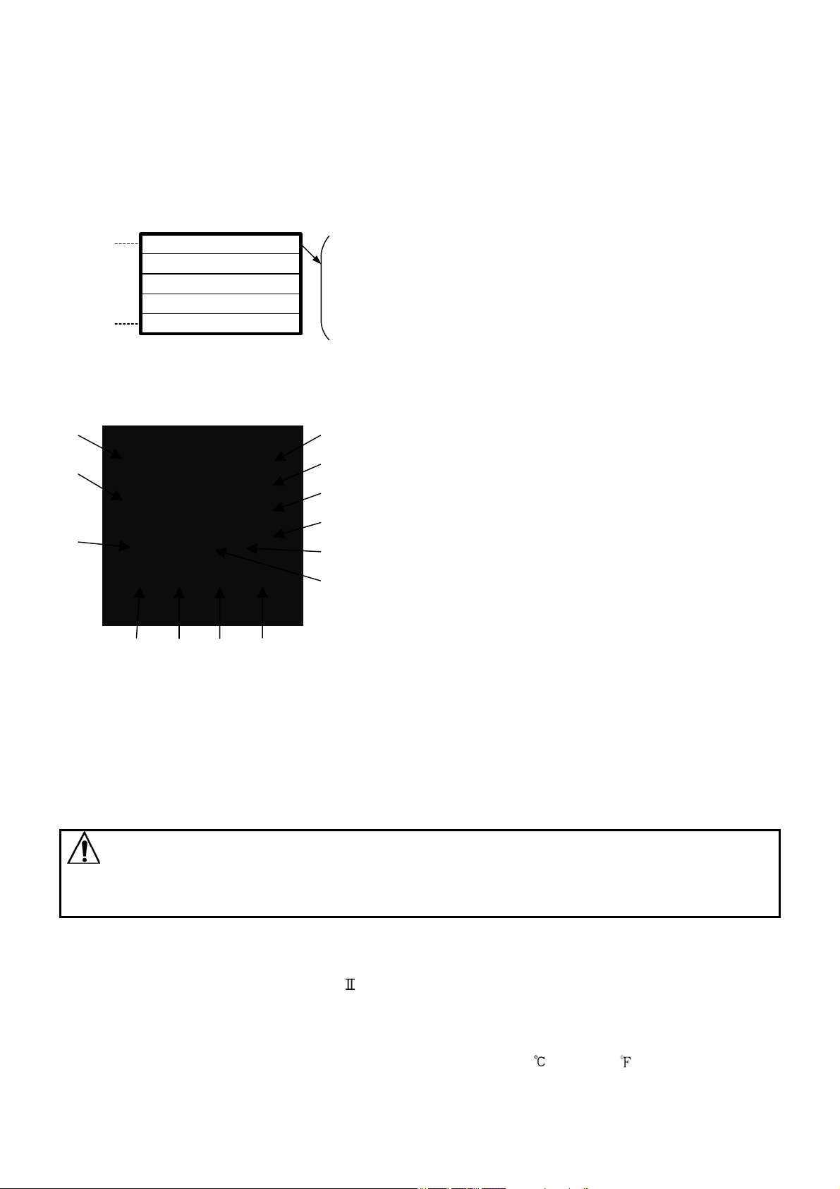
(5) Heating/Cooling control (OUT2)-- 0: Not available, 4: Non-contact relay output
CTi Automation - Phone: 800.894.0412 - Fax: 208.368.0415 - Web: www.ctiautomation.net - Email: info@ctiautomation.net
(6) Heater burnout alarm -------------- 0: Not available, 1: Available (5A), 2: Available (10A), 3: Available
(20A), 4: Available (50A)
(Heater burnout alarm is not available for the DC current output)
(7) Serial communication ------------- 1: Available (The number is indicated only when the serial
communication is applied.)
1.2 How to read the rated label
The rated label is attached to the case.
When Heater burnout alarm is added, CT rated current is written in the bracket.
(1)
(2)
(1) Model number, supply voltage, input type, output type, etc. are entered.
(2) Lot number is entered.
A K T 4 1 1 1 1 0 0 1
No.
(e.g.)
Supply voltage: 100 to 240V AC
Multi-input
Relay contact output
A1 output
Heating/Cooling control is not added.
Heater burnout alarm is not added.
Serial communcation is applied.
2. Name and functions of the sections
(1) PV display: Indicates the PV (input value) with a red LED.
(1)
(2) SV display: Indicates the SV (main set value) with a green LED.
(3) SV1 indicator: The green LED lights when SV is indicated
on the SV display.
(2)
(4) OUT1 indicator: When OUT1 or heating output is ON, a
green LED lights. (For DC current output type, it flashes
corresponding to the MV (manipulated variable) in 0.25
(3)
second cycles.
(5) OUT2 indicator: When OUT2 is ON, a yellow LED lights.
(6) A1 indicator: When A1 output is ON, a red LED lights.
(7) EVT indicator: When Event output (A2 output, Heater
burn out alarm output) is ON, a red LED lights.
(8) AT indicator: While auto-tuning or auto-reset is being
performed, the yellow LED flashes.
(Fig. 2-1) (9) TX/RX indicator: The yellow LED flashes while serial
communication is performing.
control output OFF function works.
(To cancel the function, press the OUT/OFF key again for approx. 1 second.)
(10) (11) (12) (13)
(10) Increase key : Increases the numeric value.
(11) Decrease key : Decreases the numeric value.
(12) Mode key : Selects the setting mode or registers the set value.
(By pressing the Mode key, the set value can be registered)
(13) OUT/OFF key : The control output is turned on or off. If this key is pressed for approx. 1 second,
(4)
(5)
(6)
(7)
(8)
(9)
Notice
When setting the specifications and functions of this controller, connect terminals 1 and 2 for power
source first, then set them referring to “5. Setup” and “7. Operation flowchart” before performing
“3. Mounting to the control panel” and “4. Wiring”.
3. Mounting to the control panel
3.1 Site selection
This instrument is intended to be used under the following environmental conditions
(IEC61010-1): Overvoltage category
Ensure the mounting location corresponds to the following conditions:
• A minimum of dust, and an absence of corrosive gases
• No flammable, explosive gases
• Few mechanical vibrations or shocks
• No exposure to direct sunlight, an ambient temperature of 0 to 50 (32 to 122 )
that does not change rapidly
• An ambient non-condensing humidity of 35 to 85%RH
• No large capacity electromagnetic switches or cables through which large current is flowing
• No water, oil or chemicals or where the vapors of these substances can come into direct
contact with the controller
, Pollution degree 2
2
Page 3
3.2 External dimensions (Unit: mm)
A
yp
r
(*)
)
CTi Automation - Phone: 800.894.0412 - Fax: 208.368.0415 - Web: www.ctiautomation.net - Email: info@ctiautomation.net
Gasket A
Screw t
e mounting bracket
Terminal cove
(Fig. 3.2-1)
3.3 Panel cutout (Unit: mm)
75
(Fig. 3.3-1)
3.4 CT (Current transformer) external dime nsions (Unit: mm)
48
IP66 specification may be compromised, and all
warranties will be invalidated.
45
+0.5
48
11.5
0
+0.5
45
0
n x 48-3
95
101 (*)
Lateral close mounting
+0.5
0
n: Number of unit s mounted
Caution: If lateral close mounting is used for the controller ,
44.5
59.7
48 (*)
Terminal cover (AKT4801
0
+0.5
45
AKT4815 (for 5A, 10A, 20A) AKT4816 (for 50A)
(Fig. 3.4-1)
3.5 Mounting
Mount the controller vertically to fulfill the Dust-proof/Drip-proof specification (IP66).
Mountable panel thickness: 1 to 15mm
Insert the controller from the front side of the panel.
Attach the mounting brackets by the holes at the top and bottom of the case and secure the controller
in place with the screws.
(Fig.3.5-1)
not use excessive force while
screwing in the mounting
bracket, or the case or screw
type mounting bracket could be
damaged.
The torque is approximately
0.12N•m.
Warning
s the case is made of resin, do
4. Wiring
Warning
Turn the power supply to the instrument off before wiring or checking it.
Working or touching the terminal with the power switched on may result in severe
injury or death due to Electric Shock.
3
Page 4
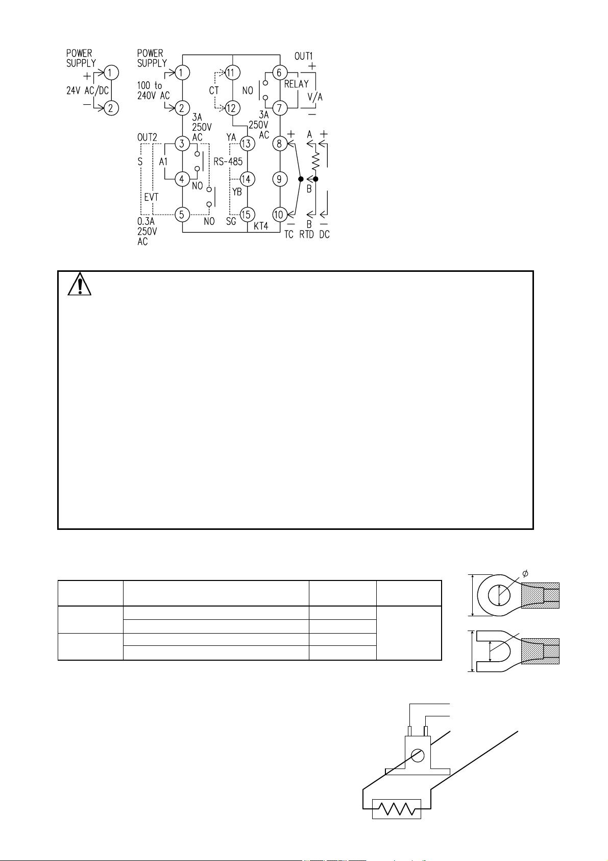
CTi Automation - Phone: 800.894.0412 - Fax: 208.368.0415 - Web: www.ctiautomation.net - Email: info@ctiautomation.net
• RELAY : Relay contact output
• OUT1 : Control output 1 (Heating output)
• OUT2 : Control output 2 (Cooling output)
• V/A : DC voltage output/DC current
output
• S : Non-contact relay output
• A1 : Alarm 1 output
• EVT : Event output (A2 output, Heater
burnout alarm output)
• CT : CT input
• TC : Thermocouple
• RTD : Resistance temperature detector
•
• DC : DC current, DC voltage
RS-485: Serial communication
(Fig. 4-1)
Notice
• The terminal block of the KT4 Series is designed to be wired from the left side.
The lead wire must be inserted from the left side of the terminal, and fastened by the
terminal screw.
• Dotted lines show options.
• Use a thermocouple and compensating lead wire according to the sensor input specification of
this controller.
• Use the 3-wire RTD which corresponds to the input specification of this controller.
• This controller does not have built-in power switch, circuit breaker or fuse. Therefore, it is
necessary to install them in the circuit near the external controller.
(Recommended fuse: Time-lag fuse, rated voltage 250V AC, rated current 2A)
• For a 24V AC/DC power source, do not confuse polarity when using direct current (DC).
• When using a relay contact output type, use a relay according to the capacity of the load to
protect the built-in relay contact.
• When wiring, keep input wires (thermocouple, RTD, etc.) away from AC sources or load wires
to avoid external interference.
• If A2 and Heater burnout alarm are applied together, they share common output terminals.
Lead wire solderless terminal
Use a solderless terminal with an insulation sleeve in which an M3 screw fits as shown below.
The torque is approximately 0.6N•m to 1.0N•m.
Solderless
terminal
Y type
Round type
Nichifu Terminal Industries CO.,LTD.
Japan Solderless Terminal MFG CO.,LTD.
Nichifu Terminal Industries CO.,LTD.
Japan Solderless Terminal MFG CO.,LTD.
Manufacturer Model
1.25Y-3
VD1.25-B3A
1.25-3
V1.25-3
(Fig. 4-2)
Tightening
torque
0.6N•m
Max. 1.0N•m
5.8mm or less
5.8mm or less
3.2mm
3.2mm
Option: Heater burnout alarm
(1) This alarm is not usable for detecting heater current
under phase control.
(2) This alarm is not usable for detecting 3-phase
heater current.
CT
(11)
CT input Terminal
(12)
Power
supply
(3) Use the current transformer (CT) provided, and pass one
lead wire of the heater circuit into the hole of the CT.
(4) When wiring, keep CT wire away from AC sources
or load wires to avoid the external interference.
(Fig. 4-3)
Heater
4
Page 5
5. Setup
CTi Automation - Phone: 800.894.0412 - Fax: 208.368.0415 - Web: www.ctiautomation.net - Email: info@ctiautomation.net
Wire the power terminals only. After the power is turned on, the sensor input character and temperature
unit are indicated on the PV display and the input range high limit value is indicated on the SV display for
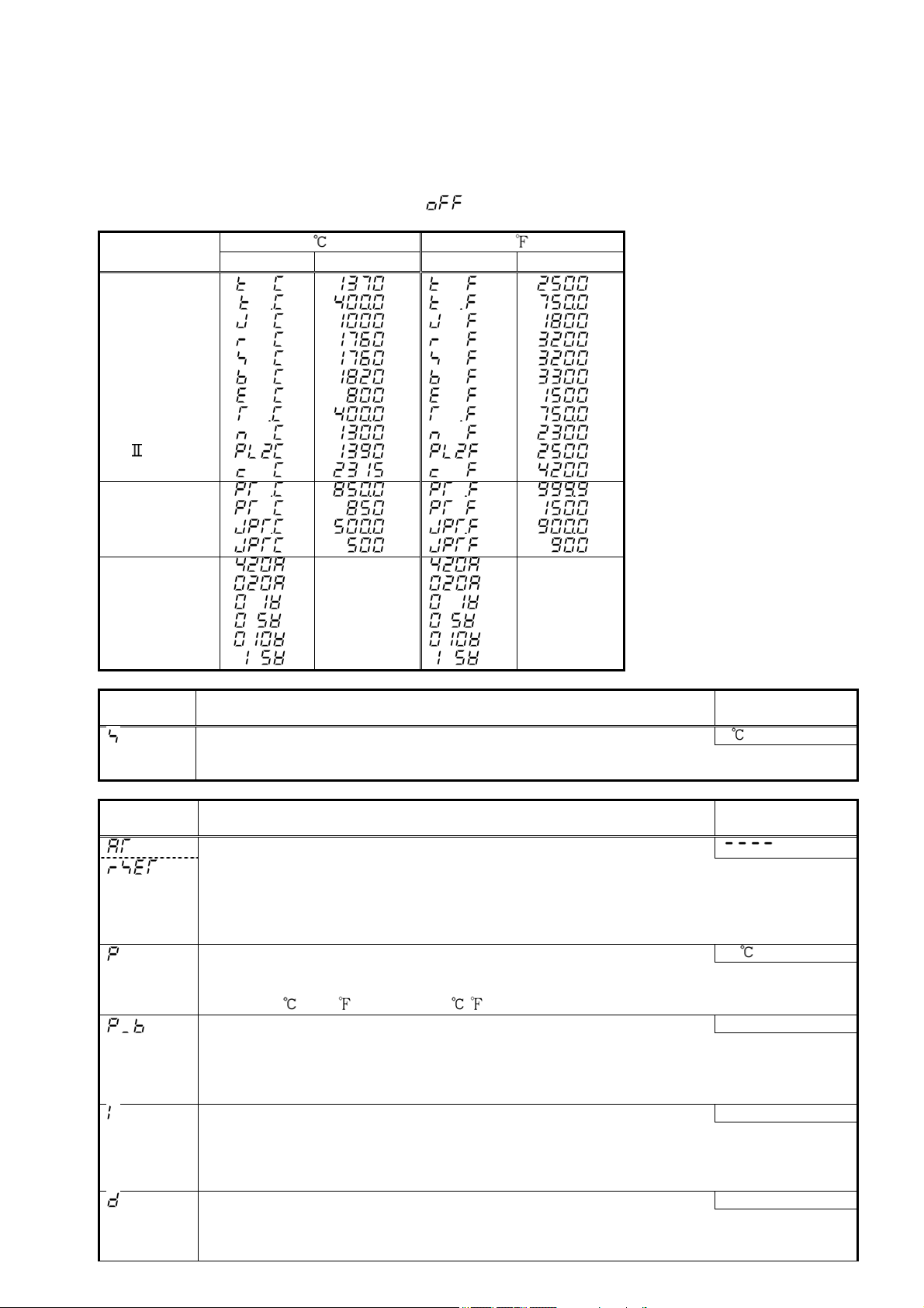
approximately 3 seconds. (Table 5-1)
(If any other value is set during the scaling high limit setting, the set value is indicated on the SV display.)
During this time, all outputs and the LED indicators are in OFF status.
Control will then start indicating the input value (PV) on the PV display and main set value (SV) on the SV display.
(While control output OFF function is working,
(Table 5-1)
Sensor input
K
J
R
S
B
E
T
N
PLC (W/Re5-26)
Pt100
JPt100
4 to 20mA DC
0 to 20mA DC
0 to 1V DC
0 to 5V DC
0 to 10V DC
1 to 5V DC
5.1 Main setting mode
Character
(PV display)
5.2 Sub-setting mode
Character
(PV display)
PV display SV display PV display SV display
SV 0
• Sets SV.
• SV low limit to SV high limit, or Scaling low limit value to scaling high limit value
AT setting/Auto-reset setting
• Selects auto-tuning Perform or auto-reset Perform.
• If the auto-tuning is cancelled during the process, P, I and D values revert to the
previous value.
• When auto-tuning has not finished after 4 hours, it is cancelled automatically.
• Auto-reset is cancelled in approximately 4 minutes.
OUT1 proportional band setting 10
• Sets the proportional band for OUT1.
• The control action becomes ON/OFF action when set to 0 or 0.0.
• 0 to 1000
OUT2 proportional band setting 1.0 times
• Sets the proportional band for OUT2.
OUT2 becomes ON/OFF action when set to 0.0.
• Available only when Heating/Cooling control (option) is applied
• 0.0 to 10.0 times (multiplying factor to OUT1 proportional band)
Integral time setting 200 seconds
• Sets the integral time.
• Setting the value to 0 disables the function.
• Auto-reset can be performed when PD is the control action (I=0).
• 0 to 1000 seconds
Derivative time setting 50 seconds
• Sets the derivative time.
• Setting the value to 0 disables the function.
• 0 to 300 seconds
Scaling high
limit value
Name, Function, Setting range
Name, Function, Setting range
(2000 ), 0.0 to 999.9 ( ) or 0.0 to 100.0%
is indicated on the PV display.)
Scaling high
limit value
5
Default value
(SV display)
Default value
(SV display)
Page 6
CTi Automation - Phone: 800.894.0412 - Fax: 208.368.0415 - Web: www.ctiautomation.net - Email: info@ctiautomation.net
ARW setting 50%
• Sets ARW (anti-reset windup).
• Available only when PID is the control action.
• 0 to 100%
OUT1 proportional cycle setting
• Sets proportional cycle for OUT1.
Relay contact output: 30 seconds
Non-contact voltage output: 3 seconds
• Not available for ON/OFF action or DC current output type.
With the relay contact type, if the proportional cycle time is decreased, the fre-
quency of the relay action increases and the life of the relay contact is shortened.
• 1 to 120 seconds
OUT2 proportional cycle setting 3 seconds
• Sets proportional cycle for OUT2.
• Not available if OUT2 is ON/OFF action
• Available only when Heating/Cooling control (option) is applied
• 1 to 120 seconds
A1 value setting 0
• Sets action point for A1 output. Setting the value to 0 or 0.0 disables the function (except
process high alarm and process low alarm).
• Not available if No alarm action is selected during A1 type selection
• Refer to (Table 5.2-1).
A2 value setting 0
• Sets action point for A2 output. Setting the value to 0 or 0.0 disables the function (except
process high alarm and process low alarm).
• Not available if No alarm action is selected during A2 type selection
• Refer to (Table 5.2-1).
.
and
measured
current
value are
indicated
alternately.
Heater burnout alarm value setting 0.0A
• Sets the heater current value for Heater burnout alarm.
• Available only when Heater burnout alarm (option) is added.
• When OUT1 is OFF, heater current value shows the same value as when OUT1 was on.
• Setting the value to 0.0 disables the function.
• It is recommended to set approx. 80% of the heater current value (set value)
considering the voltage fluctuation of power supply.
• Upon returning to set limits, the alarm will stop.
• Rating 5A : 0.0 to 5.0A Rating 10A: 0.0 to 10.0A
Rating 20A: 0.0 to 20.0A Rating 50A: 0.0 to 50.0A
(Table 5.2-1)
Alarm type Setting range
High limit alarm – (Input span) to input span ( ) *1
Low limit alarm – (Input span) to input span ( ) *1
High/Low limits alarm 0 to input span ( ) *1
High/Low limit range alarm 0 to input span ( ) *1
Process high alarm Input range low limit value to input range high limit value *2
Process low alarm Input range low limit value to input range high limit value *2
High limit alarm with standby – (Input span) to input span ( ) *1
Low limit alarm with standby – (Input span) to input span ( ) *1
High/Low limits alarm with standby 0 to input span ( ) *1
• When input has a decimal point, negative low limit value is –199.9, and positive high limit value is 999.9.
• All alarm types except process alarm are
deviation setting from the SV.
*1: For DC input, the input span is the same as the scaling span.
*2: For DC input, input range low (or high) limit value is the same as scaling low (or high) limit value.
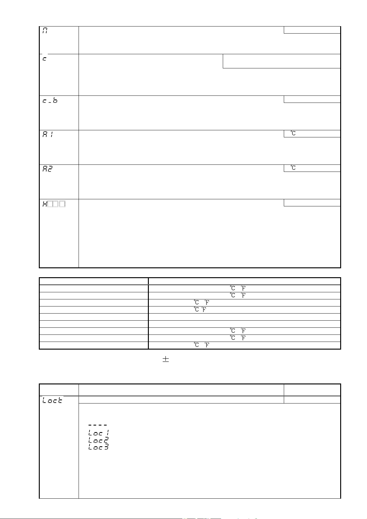
5.3 Auxiliary function setting mode 1
Character
(PV display)
Name, Function, Setting range
Set value lock selection Unlock status
Default value
(SV display)
• Locks the set values to prevent setting errors.
The setting item to be locked depends on the selection.
• When Lock 1 or Lock 2 is selected, PID Auto-tuning or Auto-reset cannot be carried out.
•
(Unlock) : All set values can be changed.
(Lock 1): None of the set values can be changed.
(Lock 2): Only main setting mode can be changed.
(Lock 3): All set values except Input type can be changed. However, they return to
their previous value after power is turn ed off because they are not saved in t he nonvolatile memory. Be sure to select Lock 3 when cha nging the set value freque ntly via
communication function. (If the value set by the communication function is the same as
the value before the setting, the value will not be written in the non-volatile memory .)
Do not change any setting item in Auxiliary function setting mode 2. If any item in
the mode is changed, it will affect other setting items such as the SV and Alarm
value.
6
Page 7

CTi Automation - Phone: 800.894.0412 - Fax: 208.368.0415 - Web: www.ctiautomation.net - Email: info@ctiautomation.net
SV high limit setting 1370
• Sets the SV high limit.
• SV low limit to input range high limit value. For DC input, SV low limit to scaling high
limit value (The placement of the decimal point follows the selection)
SV low limit setting –200
• Sets the SV low limit.
• Input range low limit value to SV high limit. For DC input, scaling low limit value to SV
high limit (The placement of the decimal point follows the selection)
Sensor correction setting 0.0
• Sets the correction value for the sensor.
• –100.0 to 100.0
( )
For DC input, –1000 to 1000 (The placement of the decimal point follows the selection)
Communication protocol selection
• Selects the communication protocol.
• Available only when Serial communication (option) is applied.
• Not available if
• Modbus ASCII mode:
Instrument number setting 0
• Sets the instrument number. (Communication cannot be carried out unless an
is indicated
, Modbus RTU mode:
instrument number is individually set when communicating by connecting plural
instruments in serial communication.)
• Available only when Serial communication (option) is added.
• 0 to 95
Communication speed selection 9600bps
• Selects a speed to be equal to the speed of the host computer.
• Available only when Serial communication (option) is added.
• 2400bps:
Parity selection Even parity
• Selects the parity.
• Not available if Serial communication (option) is not added or if
, 4800bp s: , 9600bp s: , 19200bp s:
is selected
during the Communication protocol selection.
• No parity:
Stop bit selection 1
• Selects the stop bit.
, E ven parity: , Odd parity:
• Not available if Serial communication (option) is not added or if is selected
during the Communication protocol selection.
• 1 or 2
5.4 Auxiliary function setting mode 2
Character
(PV display)
Name, Function, Setting range
Input type selection K (–200 to 1370 )
• The input type can be selected fr om thermocouple (10 types), RTD (2 types), D C
current (2 types) and DC voltage (4 types), and the unit
K –200 to 1370
–199.9 to 400.0
J –200 to 1000
R 0 to 1760
S 0 to 1760
B 0 to 1820
E –200 to 800
T –199.9 to 400.0
N –200 to 1300
PL-
0 to 1390 :
C (W/Re5-26) 0 to 2315
:
:
:
:
:
:
:
:
:
:
Pt100 –199.9 to 850.0 :
JPt100 –199.9 to 500.0
Pt100 –200 to 850
JPt100 –200 to 500
:
:
:
4 to 20mA –1999 to 9999:
0 to 20mA –1999 to 9999:
0 to 1V –1999 to 9999:
0 to 5V –1999 to 9999:
1 to 5V –1999 to 9999:
0 to 10V –1999 to 9999:
K –320 to 2500
–199.9 to 750.0
J –320 to 1800
R 0 to 3200
S 0 to 3200
B 0 to 3300
E –320 to 1500
T –199.9 to 750.0
N –320 to 2300
PL-
0 to 2500 :
C (W/Re5-26) 0 to 4200
Pt100 –199.9 to 999.9
JPt100 –199.9 to 900.0
Pt100 –300 to 1500
JPt100 –300 to 900
/ can be selected as well.
Scaling high limit setting
Default value
(SV display)
:
:
:
:
:
:
:
:
:
:
:
:
:
:
9999
• Sets scaling high limit value.
• Available only for DC input type
• Scaling low limit value to input range high limit value
(The placement of the decimal point follows the selection)
7
Page 8

CTi Automation - Phone: 800.894.0412 - Fax: 208.368.0415 - Web: www.ctiautomation.net - Email: info@ctiautomation.net
Scaling low limit setting –1999
• Sets scaling low limit value.
• Available only for DC input type
• Input range low limit value to scaling high limit value
(The placement of the decimal point follows the selection)
Decimal point place selection No decimal point
• Selects decimal point place.
• Available only for DC input
•
No decimal point: 1 digit after decimal point:
2 digits after decimal point:
PV filter time constant setting 0.0 seconds
3 digits after decimal point:
• Sets PV filter time constant.
(If the value is set too large, it affects control result due to the delay of response)
• 0.0 to 10.0 seconds
OUT1 high limit setting 100%
• Sets the high limit value of OUT1.
• Not available for ON/OFF action
• OUT1 low limit value to 105%
(Setting higher than 100% is effective to DC current output type)
OUT1 low limit setting 0%
• Sets the low limit value of OUT1.
• Not available for ON/OFF action.
• –5% to OUT1 high limit value
(Setting less than 0% is effective to DC current output type)
OUT1 ON/OFF action hysteresis setting 1.0
• Sets ON/OFF action hysteresis for OUT1.
• Available only when the control action is ON/OFF action
• 0.1 to 100.0
( )
For DC input, 1 to 1000 (The placement of the decimal point follows the selection)
OUT2 action mode selection Air cooling
• Selects OUT2 action from air cooling, oil cooling and water cooling.
• Not available if OUT2 is ON/OFF action or if Heating/Cooling control (option) is not added.
• Air cooling:
OUT2 high limit setting 100%
, oil cooling: , water cooling:
• Sets the high limit value of OUT2.
• Not available if OUT2 is ON/OFF action or if Heating/Cooling control (option) is not added.
• OUT2 low limit value to 105%
(Setting higher than 100% is effective to DC current output type)
OUT2 low limit setting 0%
• Sets the low limit value of OUT2.
• Not available if OUT2 is ON/OFF action or if Heating/Cooling control (option) is not added.
• –5% to OUT2 high limit value
(Setting less than 0% is effective to DC current output type)
Overlap band/Dead band setting 0.0
• Sets the overlap band or dead band for OUT1 and OUT2.
+ set value: Dead band – set value: Overlap band
• Not available if OUT2 is ON/OFF action or if Heating/Cooling control (option) is not added.
• –100.0 to 100.0
( )
For DC input, –1000 to 1000 (The placement of the decimal point follows the selection)
OUT2 ON/OFF action hysteresis setting 1.0
• Sets ON/OFF action hysteresis for OUT2.
• Available only when Heating/Cooling control (option) is added.
• 0.1 to 100.0 ( ),
For DC input, 1 to 1000 (The placement of the decimal point follows the selection)
A1 type selection No alarm action
• Selects an A1 type.
No alarm action :
High limit alarm :
Low limit alarm :
High/Low limits alarm :
High/Low limit range alarm:
Process high alarm :
Process low alarm :
High limit alarm with standby :
Low limit alarm with standby :
High/Low limits alarm with standby :
8
Page 9

A2 type selection No alarm action
CTi Automation - Phone: 800.894.0412 - Fax: 208.368.0415 - Web: www.ctiautomation.net - Email: info@ctiautomation.net
• Selects an A2 type.
• Available only when A2 (option) is added
• Action selection and default value are the same as those of A1 type selection.
A1 action Energized/Deenergized selection Energized
• Selects Energized/Deenergized status for A1.
• Not available if No alarm action is selected during A1 type selection
• Energized: Deenerg ized:
A2 action Energized/Deenergized selection Energized
• Selects Energized/Deenergized status for A2.
• Not available if No alarm is selected during A2 type selection or if A2 (option) is not added
• Action selection and default value are the same as those of A1 action Energized/
Deenergized selection.
A1 hysteresis setting 1.0
• Sets hysteresis for A1.
• Not available if No alarm action is selected during A1 type selection
• 0.1 to 100.0 ( )
For DC input, 1 to 1000 (The placement of the decimal point follows the selection)
A2 hysteresis setting 1.0
• Sets hysteresis for A2.
• Not available if No alarm is selected during A2 type selection or if A2 (option) is not added
• Setting range and default value are the same as those of A1 hysteresis setting.
A1 action delayed timer setting 0 seconds
• Sets action delayed timer for A1.
When setting time passes after the input enters alarm output range, the alarm is activated.
• Not available if No alarm action is selected during A1 type selection
• 0 to 9999 seconds
A2 action delayed timer setting 0 seconds
• Sets action delayed timer for A2.
When setting time passes after the input enters alarm output range, the alarm is activated.
• Not available if No alarm is selected during A2 type selection or if A2 (option) is not added
• Setting range and default value are the same as those of A1 action delayed timer setting.
Direct/ Reverse control action selection
• Selects either Reverse (Heating) or Direct (Cooling) control action.
• Reverse (Heating):
AT bias setting 20
Direct (Cooling):
Reverse
(Heating) action
• Sets bias value during PID auto-tuning.
• Not available if input type is DC current or DC voltage.
• 0 to 50
Setting item not used: This item is indicated when Serial communication (option) is
Output status selection when input abnormal Output OFF
(0 to 100 ),or 0.0 to 50.0 (0.0 to 100.0 )
added. However, this cannot be used.
• Selects the output status of OUT1 and OUT2 (option) when DC input is overscale or
underscale. See “Input abnormality indication” on pages 17, 18.
• Available only for DC current output with DC input
•
: OFF(4mA) or OUT1(OUT2) low limit
: Outputs a value between OFF(4mA) and ON(20mA) or between OUT1(OUT2)
low limit value and OUT1(OUT2) high limit value, depending on a deviation.
OUT/OFF key function selection
• Selects whether OUT/OFF key is used for control output
OUT/OFF
function
OUT/OFF function or for Auto/Manual control function.
• (OUT/OFF function) (Auto/Manual control function)
ARW function
ARW (Anti-reset windup) prevents overshoot caused by the integral action. The smaller the ARW value, the less
the overshoot caused by the integral action in the transition status, however it takes time until stabilization.
Sensor correction function
This corrects the input value from the sensor. When a sensor cannot be set at a location where control
is desired, the sensor measuring temperature ma y deviate from the temperature in the controlled
location. When controlling with plural controllers, the accuracy of sensors affects the control. Therefore,
sometimes the measured temperature (input value) does not concur.
In such a case, the control can be set at the desired temperature by adjusting the input value of sen sors.
9
Page 10

Energized/Deenergized
CTi Automation - Phone: 800.894.0412 - Fax: 208.368.0415 - Web: www.ctiautomation.net - Email: info@ctiautomation.net
When [Alarm action Energized] is selected, the alarm output (between terminals 3-4, or 3-5) is conducted
(ON) while the alarm output indicator is lit.
The alarm output is not conducted (OFF) while the alarm output indicator is not lit.
When [Alarm action De energized] is se lected, the alarm output (betwee n terminals 3-4, or 3-5) is not
conducted (OFF) while the alarm output indicator is lit.
The alarm output is conducted (ON) while the alarm output indicator is not lit.
Hig h limit alarm (When Energized is set) High limit alarm (When Deenergized is set)
(Fig. 5.4-1) (Fig. 5.4-2)
5.5 Auto/Manual control function
Auto/Manual control function
• If Auto/Manual control function is selected in the OUT/OFF key function selection, Automatic or
Manual control function can be switched by pressing the
If control action is switched from automatic to manual or vice versa, balanceless-bumpless function
works to prevent rapid change of manipulated variable.
When automatic control is switched to manual control, the 1st decimal point from the right flashes on
the SV display, and the output manipulated variable (MV) on the SV display can be increased or
decreased by pressing
By pressing the
(Whenever the power to the controller is turned on, automatic control starts.)
ON
OFF
SV setting
A1 hysteresis
ON
OFF
+ A1 set point
Name, Function
or key to perform the control.
key again, the mode reverts to the PV/SV display mode (automatic control).
SV setting
A1 hysteresis
+ A1 set point
key in the PV/SV display mode.
5.6 Control output OFF function
Character
(PV display)
5.7 Output manipulated variable (MV) indication
Output manipulated variable indication
• In the PV/SV display mode, press the
Keep pressing the key until the output manipulated variable appears, though the main setting
mode appears temporarily during the process. (The SV display indicates output manipulated variable
and a decimal point flashes in 0.5 second cycles.)
If the
Control output OFF function
• A function to pause the control action or turn the control output of the unused instrument
of the plural units OFF even if the power to the instrument is supplied.
] is indicated on the PV display while the function is working.
[
• Once the control output OFF function is enabled, the function cannot be released
even if the power to the instrument is turned OFF and ON again.
To cancel the function, press the
Name, function
key is pressed again, the mode reverts to the PV/SV display.
Name, Function
key again for approx. 1 second.
key for approx. 3 seconds.
6. Running
After the unit is mounte d to the control panel and wiring is completed, operate the unit following the
procedures below.
(1) Turn the power supply to the KT4 Series ON.
• For approx. 3sec after the power is switched ON, the sensor input character and the temperature unit
are indicated on the PV display and input range high limit value is indicated on the SV display.
See (Table 5-1). (If any other value has been set during the scaling high limit setting, the SV display
indicates it.) During this time, all outputs and LED indicators are in OFF status.
• After that, control starts indicating input value(PV) on the PV display, and main set value(SV) on the SV display .
• While the Control output OFF function is working,
(2) Input each set value, referring to “5. Setup”.
(3) Turn the load circuit power ON.
Control action starts so as to keep the control target at the main set value (SV).
10
is indicated on the PV display.
Page 11

7. Operation flowchart
[
]
y
pp
Outline of operation procedure
Operation before running
[STEP 1 Initial setting]
in Auxiliary function setting mode 2.
[STEP 2 Adjusting item]
[STEP 3 Lock setting]
[STEP 4 Run setting]
: Set Input type, Alarm type, Control action, etc.
: Set PID values and Alarm values in the
Sub setting mode.
: Set the Set value Lock, SV high limit and SV low
limit in Auxiliary function setting mode 1 (If Step 3
is not necessary, skip this step.)
: Set SV (desired value) in the Main setting mode.
Alarm 1 (A1) setting procedure
[Numbers (1) to (5) are indicated on the flowchart.]
(1) [A1 type]: Select an Alarm 1 type.
[If an alarm type except for
are indicated and they can be set if necessary.]
(2) [A1 action Energized/Deenergized]: Select Alarm 1 contact
output ON (Energized:
(3) [A1 hysteresis]: Set A1 hysteresis.
(4) [A1 action delayed timer]: Set A1 action delayed time.
(If input enters alarm action range and setting time has passed,
the alarm is activated.)
(5) [A1 value]: Set an action point of A1 output.
[Note] If an alarm type is changed, the alarm set value
becomes 0 (0.0). Therefore it is necessary to reset it.
is selected, items (2) to (5)
) or OFF (Deenergized: ).
Control output OFF function or
Auto/Manual control function
SV (Desired value)
PV
Press the key.
[Main setting mode] [Sub setting mode]
SV
SV
Reverts to PV/SV display.
Explanation of key
: This means that
is pressed, the set
if
value is saved, and the
controller proceeds to the
next setting item.
Press key for approx. 1sec.
Press the while holding down the key.
AT/Auto-reset
PV
OUT1 proportional
PV SV
OUT2 proportional
PV SV
PV SV
PV SV
PV
OUT1 proportional
PV SV
OUT2 proportional
PV SV
SV
/
Selection
band
Set value
band
Set value
Integral time
Set value
Derivative time
Set value
ARW
SV
Set value
cycle
Set value
cycle
Set value
• If AT is cancelled during the process,
PID values revert to the previous value.
• Auto-reset is automatically cancelled
in 4 minutes.
• Set the value with , keys.
• ON/OFF action when set to 0 or 0.0
• Set the value with , keys.
• Available when Heating/Cooling
• Set the value with , keys.
• PD action when set to 0.
Auto-reset can be performed.
• Set the value with , keys.
• Setting the value to 0 disables the
• Set the value with , keys.
• Available for PID action
• Set the value with , keys.
• Not available for DC current output or
if OUT1 is ON/OFF action
• Set the value with , keys.
• Not available if OUT2 is ON/OFF
action
PV/SV display
control (OUT2) is added
function.
Press the ke
Press the key
for approx. 3sec.
Press for a
Set value Lock
PV
PV
PV
Sensor correction
PV
Communication protocol
PV
Instrument number
PV
Communication speed
PV
PV
SV
Selection
SV high limit
SV
SV low limit
SV
SV
SV
Selection
SV
SV
Parity
SV
.
Output MV indication
rox. 3sec while holdingdown .
Auxiliary function setting mode 1
• Make a selection with
keys.
• If Lock 1 or Lock2 is designated,
AT or Auto-reset does not work.
• Be sure to select Lock 3 when
using Serial communication.
Set value
Set value
Set value
Set value
Selection
Selection
• Set the value with
• Set the value with , keys.
• Set the value with
• Make a selection with ,
keys.
• Not available for
• Set the value with , keys.
• Make a selection with ,
keys.
• Make a selection with ,
keys.
• Not available if
during Communication protocol
selection
,
, keys.
, keys.
indication
is selected
(5)
A1 value
PV SV
A2 value
PV SV
Set value
Set value
• Set the value with , keys.
• Not available if
during A1 type selection
• Set the value with , keys.
• Not available if
during A2 type selection
is selected
is selected
Stop bit
PV
SV
Selection
Reverts to the PV/SV display.
• Make a selection with
• Not available if
during Communication protocol
selection
, keys.
is selected
Setting items with dotted lines are optional
Heater burnout alarm value
PV
.
SV
Set value
• Set the value with
• OFF when set to 0.0
, keys.
and they appear only when the options are
added.
Reverts to the PV/SV display.
11
Page 12

8. Action explanation
CTi Automation - Phone: 800.894.0412 - Fax: 208.368.0415 - Web: www.ctiautomation.net - Email: info@ctiautomation.net
8.1 OUT1 action
Control
action
Relay contact
output
Non-contact
voltage output
DC current
output
Indicator
(OUT1) Green
: Acts ON or OFF.
8.2 EVT (Heater burnout alarm) action
Heating (Reverse) action Cooling (Direct) action
Proportional band
ON
OFF
6
7
Cycle action is performed according to deviation
+
6
12V DC
7
Cycle action is performed according to deviation Cycle action is performed according to deviation
+
6
20mA DC 20 to 4mA DC
7
Changes continuously according to deviation
Lit Unlit
6
7
6
++
12/0V DC
7
6
7
SV setting
6
7
6
0V DC
7
6
4mA DC
7
Unlit
Proportional band
ON
OFF
SV setting
6
7
Cycle action is performed according to deviation
++
6
0V DC 12V DC
7
+++
6
4mA DC
7
Changes continuously according to deviation
6
7
6
0/12V DC
7
6
4 to 20mA DC
7
6
7
+
6
7
++
6
20mA DC
7
Lit
Alarm action
ON
OFF
8.3 OUT1 ON/OFF action
Control
action
ON
OFF
Relay contact
output
6
7
+
Non-contact
voltage output
6
7
++
DC current
output
6
20mA DC
7
Indicator
(OUT1) Green
Lit
: Acts ON or OFF.
Setting
Load current
Output
LargeSmall
Indicator
3
5
3
5
UnlitLit
Heating (Reverse) action Cooling (Direct) action
Hysteresis
SV setting
6
7
6
+
7
6
4mA DC
7
6
7
+
6
0V DC12V DC
Unlit
0V DC 12V DC
7
6
+
4mA DC
7
Hysteresis
SV setting
+
+
20mA DC
ON
OFF
6
7
6
7
6
7
LitUnlit
12
Page 13

Press the and keys for approx. 3 seconds.
[
Input type (character indication) and range
K –200 to 1370 :
–199.9 to 400.0
J –200 to 1000
R 0 to 1760
S 0 to 1760
B 0 to 1820
E –200 to 800
T –199.9 to 400.0
N –200 to 1300
0 to 1390 :
PL-
(W/Re5-26)
C
0 to 2315 :
:
:
:
:
:
:
:
:
Pt100 –199.9 to 850.0 :
JPt100 –199.9 to 500.0
Pt100 –200 to 850
JPt100 –200 to 500
:
:
:
K –320 to 2500
–199.9 to 750.0 :
J –320 to 1800
R 0 to 3200 :
S 0 to 3200 :
B 0 to 3300 :
E –320 to 1500 :
T –199.9 to 750.0 :
N –320 to 2300 :
PL- 0 to 2500 :
C
(W/Re5-26)
0 to 4200
Pt100 –199.9 to 999.9
JPt100 –199.9 to 900.0 :
Pt100 –30 0 to 1500
JPt100 –300 to 900 :
4 to 20mA DC –1999 to 9999:
0 to 20mA DC –1999 to 9999:
0 to 1V DC –1999 to 9999:
0 to 5V DC –1999 to 9999:
1 to 5V DC –1999 to 9999:
0 to 10V DC –1999 to 9999:
:
:
:
:
:
Alarm type
High limit alarm: The alarm action is deviation setting from the SV. The alarm is activated
if the input value reaches the high limit set value. Character indication:
Low limit alarm: The alarm action is
deviation setting from the SV. The alarm is activated
if the input value goes under the low limit set value. Character indication:
High/Low limits alarm: Combines High limit and Low limit alarm actions. When input value
reaches high limit set value or goes under the low limit set value, the alarm
is activated. Character indication:
High/Low limit range alarm: When input value is between the high limit set value and low
limit set value, the alarm is activated. Character indication:
Process alarm: Within the scale range of the controller, alarm action points can be set
at random and if the input reaches the randomly set action point, the alarm is
activated.
Character indication: Process high alarm
, Process low alarm
Alarm with standby function: When the power to the controller is turned on, even if the input
enters the alarm action range, the alarm is not activated. (If the controller is
allowed to keep running, once the input exceeds the alarm action point, the
standby function will be released.)
Character indication:
High limit alarm with standby :
Low limit alarm with standby :
High/Low limits alarm with standby :
PV
Input type
Scaling high limit
PV
Scaling low limit
PV
Decimal point place
PV
PV filter time
constant
PV
OUT1 high limit
PV
OUT1 low limit
PV
OUT1 ON/OFF action
hysteresis
PV
OUT2 action mode
PV
OUT2 high limit
PV
OUT2 low limit
PV
Overlap/Dead band
PV
OUT2 ON/OFF action
hysteresis
PV
Press the
and keys for approx. 3 seconds.
Auxiliary function setting mode 2]
SV
Selection
SV
Set value
SV
Set value
SV
Selection
SV
Set value
SV
Set value
SV
Set value
SV
Set value
SV
Selection
SV
Set value
SV
Set value
SV
Set value
SV
Set value
• Make a selection with the
• Default value:
• Set the value with the
• Available for DC current, DC voltage input
• Set the value with the
• Available for DC current, DC voltage input
• Make a selection with the
• Available for DC current, DC voltage input
• Set the value with the
• Set the value with the
• Not available for ON/OFF action
• Set the value with the
• Not available for ON/OFF action
• Set the value with the
• Available for ON/OFF action
• Make a selection with the , keys.
• Available if Heat/Cool control (OUT2) is added
• Set the value with the
• Available if Heat/Cool control (OUT2) is added
• Set the value with the
• Available if Heat/Cool control (OUT2) is added
• Set the value with the
• Available only when Heat/Cool control (OUT2) is
added
• Set the value with
• Available only when Heat/Cool control (OUT2) is
added
, keys.
, keys.
, keys.
, keys.
, keys.
, keys.
, keys.
, keys.
, keys.
, keys.
, keys.
, keys.
(1)
(2)
A1 type
PV SV
A2 type
PV SV
A1 action Energized/
Deenergized
PV SV
A2 action Energized/
Deenergized
PV SV
(3)
A1 hysteresis
PV SV
A2 hysteresis
PV SV
A1 action delayed
(4)
PV SV
A2 action delayed
PV SV
Direct/Reverse control
PV SV
AT b ias
PV SV
Setting item not used
PV SV
Output status selection
when input abnormal
PV SV
Selection
Selection
Selection
Selection
Set value
Set value
timer
Set value
timer
Set value
Selection
Set value
Set value
Selection
• Make a selection with the , keys.
• Default value:
• Make a selection with the , keys.
• Available when A2 is added
• Make a selection with the , keys.
• Not available if
is selected during A1
type selection
• Make a selection with the , keys.
• Not available if
is selected during A2
type selection
• Set the value with the , keys.
• Not available if
type selection
• Set the value with the , keys.
• Not available if
type selection
is selected during A1
is selected during A2
• Set the value with the , keys.
• Not available if
is selected during A1
type selection
• Set the value with the , keys.
• Not available if
is selected during A2
type selection
• Make a selection with the , keys.
• Default value:
• Set the value with the , keys.
• Available for thermocouple, RTD input
• Do not set this item even if is indicated
on the PV display.
• Make a selection with the , keys.
• Available only when input is DC current and DC
voltage with DC current output.
OUT/OFF key function
13
PV SV
Selection
Reverts to the PV/SV display.
• Make a selection with the , keys.
Page 14

8.4 A1 and A2 action
Alarm
action
ON
OFF
High limit alarm
SV
setting
High/Low limit range alarm
A1 hysteresis
+ A1 set pointA1 set point
A1 hysteresis A1 hysteresis A1 hysteresis
ON
OFF
A1 hysteresis
A1 set point
SV
+ A1 set point
setting
Process high alarm
ON
OFF
A1 set point
Alarm
action
ON
OFF
High limit alarm with standby High/Low limit alarm with standbyLow limit alarm with standby
SV
setting
A1 hysteresis A1 hysteresis A1 hysteresis
ON
OFF
ON
OFF
Alarm
action
ON
OFF
A1 set point
SV
setting
+ A1 set point
: Standby functions in this section.
ON
OFF
A1 set point
SV
setting
+ A1 set point
ON
OFF
A1 set point A1 set pointSV
A1 indicator lights when its output terminals 3 and 4 are connected (ON), and goes off when
they are not connected (OFF).
A2 indicator lights when its output terminals 3 and 5 are connected (ON), and goes off when
they are not connected (OFF).
8.5 Heating/Cooling control action
Control action
Relay contact
output (OUT1)
Heating P-band
ON
Heating
action
OFF
Cycle action is performed according to deviation.
(Cooling P-band)
ON
(Cooling
action)
OFF
SV setting
666
777
6
Non-contact
voltage output
(OUT1)
DC current
output (OUT1)
Non-contact
relay output
(OUT2)
Indicator
(OUT1) Green
Indicator
(OUT2) Yellow
+
12V DC
7
-
Cycle action is performed according to deviation.
6
+
20mA DC
7
-
Changes continuously according to deviation.
Lit
Unlit
: Acts ON (lit) or OFF (unlit).
: Represents Heating control action.
: Represents Cooling control action.
6
+
12/0V DC
7
-
6
+
20 to 4mA DC
7
-
Cycle action is performed according to deviation.
+
-
+
-
6
0V DC
7
6
4mA DC
7
333
555
Unlit
Lit
14
High/Low limits alarmLow limit alarm
SV
setting
Process low alarm
A1 set pointA1 set pointA1 set pointA1 set point
setting
A1 hysteresis
A1 set point
Page 15

8.6 Heating/Cooling control action (when setting dead band)
CTi Automation - Phone: 800.894.0412 - Fax: 208.368.0415 - Web: www.ctiautomation.net - Email: info@ctiautomation.net
Control action
Relay contact
output (OUT1)
Non-contact
voltage output
(OUT1)
DC current
output (OUT1)
Non-contact
relay output
(OUT2)
Indicator
(OUT1) Green
Indicator
(OUT2) Yellow
ON
Heating
action
OFF
Cycle action is performed according to deviation.
6
+
12V DC
7
-
Cycle action is performed according to deviation.
6
+
20mA DC
7
-
Changes continuously according to deviation.
Lit
Unlit Lit
Heating P-band (Cooling P-band)
SV setting
6
+
12/0V DC
7
-
6
+
20 to 4mA DC
7
-
Dead band
(Cooling
action)
666
777
6
+
0V DC
7
-
6
+
4mA DC
7
-
3 3 3
5 5 5
Cycle action is performed according to deviation.
ON
OFF
Unlit
: Acts ON (lit) or OFF (unlit).
: Represents Heating control action.
: Represents Cooling control action.
8.7 Heating/Cooling control action (when setting overlap band)
Control action
Relay contact
output (OUT1)
Non-contact
voltage output
(OUT1)
DC current
output
(OUT1)
Non-contact
relay output
(OUT2)
Indicator
(OUT1) Green
Indicator
(OUT2) Yellow
ON
Heating
action
OFF
Cycle action is performed according to deviation.
6
+
12V DC
7
-
Cycle action is performed according to deviation.
6
+
20mA DC
7
-
Changes continuously according to deviation.
Lit
Unlit
Heating p-band
Cooling p-band
Overlap band
(Cooling
action)
SV setting
666
777
6
+
12/0V DC
7
-
6
+
20 to 4mA DC
7
-
+
-
+
-
6
0V DC
7
6
4mA DC
7
3 3 3
555
Cycle action is performed according to deviation.
Unlit
ON
OFF
Lit
: Acts ON (lit) or OFF (unlit).
: Represents Heating control action.
: Represents Cooling control action.
9. PID auto-tuning of this controller
In order to set each value of P, I, D and ARW automatically, the auto-tuning process should be made
to fluctuate to obtain an optimal value. One of 3 types of fluctuation below is automatically selected.
Sometimes the auto-tuning process will not fluctuate if auto-tuning is performed at or near room
temperature. Therefore auto-tuning might not finish normally.
15
Page 16

(1) In the case of a large difference between the SV and processing temperature (PV) as the
CTi Automation - Phone: 800.894.0412 - Fax: 208.368.0415 - Web: www.ctiautomation.net - Email: info@ctiautomation.net
temperature is rising
When AT bias is set to 20
Temp.
SV
Temperature 20
(4)
, the AT process will fluctuate at the temperature 20 lower than the SV.
lower than the SV
Calculating PID constant
(1):
PID contatnt calculated
(2):
Controlled by the PID
(3):
constant set by auto-tuning.
(4):
AT bias value
AT
(1) (2) (3)
Time
:
Auto-tuning starting point
AT
(2) In the case of a stable control
The AT process will fluctuate around the SV.
Temp.
SV
Calculating PID constant
(1):
(2):
PID constant calculated
Controlled by the PID
(3):
constant set by auto-tuning
AT
(1) (2) (3)
Time
:
Auto-tuning starting point
AT
(3) In the case of a large difference between the SV and processing temperature (PV)
as the temperature is falling.
When AT bias is set to 20
Temp.
SV
(4)
Temperature 20 higher than the SV
, fluctuation is applied at the te mperature 20 higher tha n the SV .
(1): Calculating PID constant
(2): PID constant calculated
(3):
Controlled by the PID
constant set by auto-tuning
(4): AT bias value
:AT
AT
(1) (2) (3)
Time
Auto-tuning starting point
10. Specifications
10.1 Standard specifications
Mounting : Flush
Setting : Input system using membrane sheet key
Display PV display : Red LED 4 digits, character size 10.2 x 4.9 mm (H x W)
SV display : Green LED 4 digits, character size 8.8 x 4.9 mm (H x W)
Accuracy (Setting and Indication):
Thermocouple : Within
whichever is greater
However, for R, S input, 0 to 200
B input, 0 to 300
K, J, E, T, N input, less than 0
RTD : Within
within
DC current : Within
DC voltage : Within
Input sampling period : 0.25 seconds
Input Thermocouple : K, J, R, S, B, E, T, N, PL-
(However, for B input: External resistance, 40
RTD : Pt100, JPt100, 3-wire system
Allowable input lead wire resistance (10
DC current : 0 to 20mA DC, 4 to 20mA DC
Input impedance: External shunt resistor (AKT4810) 50
Allowable input current (50mA or less)
DC voltage : 0 to 1V DC Input impedance (1M
Allowable input voltage (5V or less)
Allowable signal source resistance (2k
0.2% of each input span 1digit, or within 2 (4 ),
(400 ): Within 6 (12 )
(600 ): Accuracy is not guaranteed
(32 ): Within 0.4% of input span 1digit
0.1% of each input span 1digit, or
1 (2 ), whichever is greater
0.2% of each input span 1digit
0.2% of each input span 1digit
, C(W/Re5-26) External resistance, 100 or less
or less)
or less per wire)
or more)
or less)
16
Page 17

: 0 to 5V DC, 1 to 5V DC, 0 to 10V DC Input impedance (100k
CTi Automation - Phone: 800.894.0412 - Fax: 208.368.0415 - Web: www.ctiautomation.net - Email: info@ctiautomation.net
or more)
Allowable input voltage (15V or less)
Allowable signal source resistance (100
or less)
Control output (OUT1)
Relay contact : 1a, Control capacity 3A 250V AC (resistive load)
1A 250V AC (inductive load cosø=0.4)
Electrical life, 100,000 cycles
Non-contact voltage (For SSR drive): 12
DC current : 4 to 20mA DC, Load resistance, maximum 550
+2
V DC maximum 40mA (short circuit protected)
0
A1 output
Action : ON/OFF action
Hysteresis : 0.1 to 100.0
( ), or 1 to 1000
Output : Relay contact, 1a
Control capacity, 3A 250V AC (resistive load)
Electrical life, 100,000 cycles
Control action
PID action (with auto-tuning function)
PI action: When derivative time is set to 0
PD action (with auto-reset function): When integral time is set to 0
P action (with auto-reset function): When both derivative and integral times are set to 0.
ON/OFF action: When proportional band is set to 0 or 0.0
OUT1 proportional band : 0 to 1000
(2000 ), 0.0 to 999.9 ( ) or 0.0 to 100.0%
(ON/OFF action when set to 0 or 0.0)
Integral time : 0 to 1000sec (OFF when set to 0)
Derivative time : 0 to 300sec (OFF when set to 0)
OUT1 proportional cycle : 1 to 120sec (Not available for DC current output type)
ARW : 0 to 100%
OUT1 output hysteresis : 0.1 to 100.0
( ), or 1 to 1000
OUT1 output limit : 0 to 100% (DC current output type: –5 to 105%)
Circuit insulation configuration
Insulation resistance : 10M
1
Power
Power
supply
2
3
4
5
A1
EVT (A2, Heater burnout
alarm) or OUT2
or more, at 500V DC
11
12
Insulation
CT
input
Commu-
nication
Output
13
14
15
CPU
Input
6
7
8
9
10
Dielectric strength : 1.5kV AC for 1 minute between input terminal and power terminal
1.5kV AC for 1 minute between output terminal and power terminal
Supply voltage : 100 to 240V AC 50/60Hz, 24V AC/DC 50/60Hz
Allowable voltage fluctu atio n: 100 to 240V AC: 85 to 264V AC, 24V AC/DC: 20 to 28V AC/DC
Power consumption : Approx. 8VA
Ambient temperature
: 0 to 50 (32 to 122 )
Ambient humidity : 35 to 85%RH (no condensation)
Weight : Approx. 200g
External dimension : 48 x 48 x 96.5mm (W x H x D)
Material : Flame-resistant resin (Case)
Color : Ash gray (Case)
Attached function :
[Set value lock], [Sensor correct ion], [A uto/ma nu al cont ro l switching],
[Input abnormality indication]
Output status
Output status
selection when
input abnormal
Contents and
Indication
Overscale
Measured value
has exceeded
Indication range
high limit value.
"
" flashes.
Underscale
Measured value
has dropped below
Indication range low
limit value.
"
" flashes.
Direct action Reverse action Direct action
ON (20mA) or
OUT1 high
limit value
OFF (4mA) or
OUT1 low
limit value
OFF (4mA) or
OUT1 low
limit value
OUT1 OUT2
Reverse action
ON or
OFF (4mA) or
OUT1 low limit
value
OFF or
OUT2 low limit
value
OUT2 high limit
value
OFF or
OUT2 low limit
value
ON (20mA) or
OUT1 high
limit value
OFF (4mA) or
OUT1 low limit
value
ON or
OUT2 high limit
value
OFF or
OUT2 low limit
value
OFF or
OUT2 low limit
value
Only for DC input and DC current output type, [Output status selection when input abnormal] is
available. For other inputs and outputs except for DC input and DC current output, the output status
will be the same one as when OFF is selected during [Output status selection when input abnormal].
For manual control, the preset MV (manipulated variable) is outputted.
17
Page 18

Thermocouple and RTD input
CTi Automation - Phone: 800.894.0412 - Fax: 208.368.0415 - Web: www.ctiautomation.net - Email: info@ctiautomation.net
Input Input range Indication range Control range
K,T
–199.9 to 400.0 –199.9 to 450.0 –205.0 to 450.0
–199.9 to 750.0
–199.9 to 850.0 –209.0 to 850.0
–199.9 to 850.0 –199.9 to 900.0 –210.0 to 900.0
Pt100
–200 to 850 –210 to 900 –210 to 900
–199.9 to 999.9 –199.9 to 999.9 –211.0 to 1099.9
–300 to 1500
–318 to 1600 –318 to 1600
–199.9 to 500.0 –199.9 to 550.0 –206.0 to 550.0
JPt100
–200 to 500 –207 to 550 –207 to 550
–199.9 to 900.0 –199.9 to 999.9 –211.0 to 999.9
–300 to 900
–312 to 1000 –312 to 1000
Indication range and Control range for the thermocouple inputs except the above:
[Input range low limit value – 50
(100 )] to [input range high limit value + 50 (100 )]
DC current and voltage input
Indication range : [Scaling low limit value – Scaling span x 1%] to [Scaling high limit value
+Scaling span x 10%]
(If the input value is out of the range –1999 to 9999, the PV display flashes
“
” or “ ”)
Control range : [Scaling low limit value – Scaling span x 1%] to [Scaling high limit value
+Scaling span x 10%]
DC input disconnection: When DC input is disconnected, PV display flashes “
20mA DC and 1 to 5V DC inputs, and “
” for 0 to 1V DC input.
” for 4 to
For 0 to 20mA DC, 0 to 5V DC and 0 to 10V DC inputs, the PV display
indicates the value corresponding with 0mA or 0V input.
[Burnout]: When the thermocouple or RTD input is burnt out, OUT1 is turned OFF (for DC current
output type, OUT1 low limit value) and PV display flashes “
”.
[Self-diagnosis]: The CPU is monitored by a watchdog timer, and when an abnormal status is
found on the CPU, the controller is switched to warm-up status.
[Automatic cold junction temperature compensation] (Only thermocouple input type)
This detects the temperature at the connecting terminal between the thermocouple and instrument,
and always keeps it set to the same status as when the reference junction is located at 0
[Power failure countermeasure]:
The setting data is backed up in the non-volatile memory.
[Warm-up indication]
After the p ower supply to the instrument is turned on, the sensor input character an d
temperature unit are indicated on the PV display and input range high limit value is indicated on
the SV display for 3 seconds.
For DC current and voltage inputs, the scaling high limit value is indicated.
Accessories included: Screw type mounting bracket 1 set, Instruction manual 1 copy
CT (Current transformer); For rating 5A, 10A, 20A (AKT4815) 1 piece
For rating 50A, (AKT4816) 1 piece
Accessories sold separately: Terminal cover (AKT4801) 1 piece, 50
shunt resistor (AKT4810) 1 piece
(32 ).
10.2 Optional specifications
Alarm 2 (A2)
If A2 and Heater burnout alarm are applied together, they utilize common output terminals.
Action : ON/OFF action
Hysteresis : 0.1 to 100.0
( ), or 1 to 1000
Output : Relay contact, 1a
Control capacity, 3A 250V AC (Resistive load)
Electrical life, 100,000 cycles
Heater burnout alarm (including sensor burnout alarm)
Watches the heater current with CT (current transformer), and detects the burnout.
This alarm is also activated when indication is overscale and underscale.
(To detect Heater burnout, a CT for 50A can also be used for 5A, 10A and 20A ratings, however, this
is not suitable for small ampere ratings due to a low degree of accuracy. For a 20A rating or less, use
a CT designated for 20A.)
This option cannot be applied to DC current output type.
If A2 and Heater burnout alarm are applied together, they utilize common output terminals.
Rating : 5A, 10A, 20A, 50A (Must be specified)
Setting range : 5A, 0.0 to 5.0A (Off when set to 0.0) 10A, 0.0 to 10.0A (Off when set to 0.0)
20A, 0.0 to 20.0A (Off when set to 0.0) 50A, 0.0 to 50.0A (Off when set to 0.0)
Setting accuracy : Within
5% of the rated value
Action : ON/OFF action
Output : Relay contact 1a
Control capacity, 3A 250V AC (resistive load)
Electrical life, 100,000 cycles
18
Page 19

Heating/Cooling control (OUT2)
CTi Automation - Phone: 800.894.0412 - Fax: 208.368.0415 - Web: www.ctiautomation.net - Email: info@ctiautomation.net
• OUT2 side
Proportional band: 0.0 to 10.0 times OUT1 proportional band (ON/OFF action when set to 0.0)
Proportional cycle: 1 to 120 seconds
• Overlap band/Dead band setting range
Thermocouple, RTD inputs: –100.0 to 100.0
DC current, DC voltage inputs: –1000 to 1000 (The placement of the decimal point follows the selection)
( )
• OUT2 output ON/OFF action hysteresis setting
Thermocouple, RTD inputs: 0.1 to 100.0
DC current, DC voltage inputs: 1 to 1000 (The placement of the decimal point follows the selection)
( )
• Integral and derivative times are the same as those of OUT1.
• OUT2 action mode selection function
Air cooling (linear characteristic), Oil cooling (1.5th power of the linear characteristic),
Water cooling (2nd power of the linear characteristic)
• Output: Non-contact relay, Control capacity; 0.3A 250V AC
Serial communication
The following operations can be carried out from the external computer.
(1) Reading and setting of SV, PID and various set values
(2) Reading of the PV and action status
(3) Change of the functions
Cable length : Max. communication distance 1000m, Cable resistance; Within 50
Communication interface : EIA RS-485
Communication method : Half-duplex communication start stop synchronous
Communication speed : 2400, 4800, 9600, 19200bps (Selectable by keypad operation)
Parity : Even, Odd and No parity (Selectable by keypad operation)
Stop bit : 1, 2 (Selectable by keypad operation)
Communication protocol : Modbus RTU, Modbus ASCII (Selectable by keypad operation)
Connectable number of units : Maximum 31 units to 1 host computer
Communication error detection : Parity, checksum (LRC, CRC)
11. Tr oubleshooting
If any malfunctions occur, refer to the following items after checking the power supply to the controller.
11.1 Indication
Problem
PV display is indicating [ ].
[ ] is flashing on the PV
display.
[ ] is flashing on the PV
display.
• Control output OFF function is working.
Press the
• Thermocouple, RTD or DC voltage (0 to 1V DC) is burnt out.
Change each sensor.
How to check whether the sensor is burnt out
[Thermocouple]
If the input terminal of the instrument is shorted, and if a value
around room temperature is indicated, the instrument is likely to
be operating normally, however, sensor may be burnt out.
[RTD]
If approx. 100
between A-B of the instrument and between B-B is shorted, and
if approximate 0
operating normally, however, the sensor may be burnt out.
[DC voltage (0 to 1V DC)]
If the input terminal of the instrument is shorted, and if a scaling
low limit value is indicated, the instrument is likely to be operating
normally, however, the signal wire may be disconnected.
• Check whether the input terminals of thermocouple, RTD or DC voltage
(0 to 1V DC) are securely mounted to the instrument input terminals.
Connect the sensor terminal to the instrument input terminal securely.
• Check whether the input signal source of DC voltage (1 to 5V DC)
or DC current (4 to 20mA DC) is disconnected.
How to check whether the input signal wire is disconnected
[DC voltage (1 to 5V DC)]
If the input to the input terminal of the instrument is 1V DC and if
a scaling low limit value is indicated, the instrument is likely to be
operating normally, however, the signal wire may be disconnected.
[DC current (4 to 20mA DC)]
If the input to the input terminal of the instrument is 4mA DC and
if a scaling low limit value is indicated, the instrument is likely to be
operating normally, however, the signal wire may be disconnected.
• Check if the input signal wire of DC voltage (1 to 5V DC), DC current
(4 to 20mA DC) is securely connected to the instrument input terminals.
Connect the signal lead wire to the instrument input terminal securely.
19
Presumed cause and solution
key for approx. 1 second to release the function.
of resistance is connected to the input terminals
(32 ) is indicated, the instrument is likely to be
Page 20

[
CTi Automation - Phone: 800.894.0412 - Fax: 208.368.0415 - Web: www.ctiautomation.net - Email: info@ctiautomation.net
] is flashing on the PV
display.
The PV display keeps indicating
the value which was set during
scaling low limit value.
The indication of PV display is
abnormal or unstable.
The PV display is indicating
[
].
11.2 Key operation
Problem
• Unable to set the SV, P, I, D,
proportional cycle or alarm
setting
• The values do not change by
, keys.
The setting indication does not
change in the input range even if
the
and new values are unable to be set.
, keys are pressed,
11.3 Control
Problem
Temperature does not rise.
The control output remains in
an ON status.
The control output remains in
an OFF status.
• Check whether the polarity of thermocouple or compensating lead
wire is correct.
• Check whether codes (A, B, B) of RTD agree with the instrument
input terminals. Ensure that they are wired properly.
• Check whether the input signal source for DC voltage (0 to 5V DC,
0 to 10V DC) and DC current (0 to 20mA DC) is disconnected.
How to check whether the input signal wire is disconnected
[DC voltage (0 to 5V DC, 0 to 10V DC)]
If the input to the input terminal of the instrument is 1V DC and if a
value corresponding to 1V DC is indicated, the instrument is likely to
be operating normally, however, the signal wire may be disconnected.
[DC current (0 to 20mA DC)]
If the input to the input terminal of the instrument is 1mA DC and if a
value corresponding to 1mA DC is indicated, the instrument is likely to
be operating normally, however, the signal wire may be disconnected.
• Check whether the input terminal of DC voltage (0 to 5V DC, 0 to
10V DC) and DC current (0 to 20mA DC) is securely mounted to the
instrument input terminals. Ensure that DC input terminals are
mounted to the instrument input terminals securely.
• Check whether sensor input or temperature unit (
Select the sensor input and temperature unit (
or ) is correct.
or ) properly.
• Sensor correcting value is unsuitable. Set it to a suitable value.
• Check whether the specification of the sensor is correct.
Set the sensor to the proper specification.
• AC leaks into the sensor circuit. Use an ungrounded type sensor.
• There may be equipment that interferes with or makes noise near
the controller.
Keep equipment that interferes with or makes noise away from the
controller.
• Internal memory is defective.
Contact our agency or us.
Presumed cause and solution
• Set value lock (Lock 1 or Lock 2) has been selected.
Release the lock selection.
• During PID auto-tuning or auto-reset.
In the case of PID auto-tuning, cancel auto-tuning.
It takes approximately 4 minutes until auto-reset is finished.
• SV high or low limit value in the Auxiliary function setting mode 1
may be set at the point where the value does not change.
Set it to a suitable value while in the Auxiliary function setting mode 1.
Presumed cause and solution
• Sensor is out of order.
Change the sensor.
• Check whether the sensor is se curely mounted to the instrument
input terminal.
Check whether control output terminals are se curely mounted
to the actu ator input terminals.
Mount the sensor or control output terminal securely.
• Ensure that the wiri ng of sensor or contro l output terminal is
correct.
• OUT1 or OUT2 low limit value is set to 100% or higher
during Auxiliary function setting mode 2.
Set it to a suitable value.
• OUT1 or OUT2 high limit value is set to 0% or less during
Auxiliary function setting mode 2.
Set it to a suitable value.
20
 Loading...