

Page 1
TEMPERATURE CONTROLLER
KT2
INSTRUCTION MANUAL
Page 2
PPrreeffaacce
Caution
Thank you for purchasing Temperature Controller KT2.
This manual contains instructions for the mounting, functions, operations and notes for operating the KT2.
For model confirmation and unit specifications, please read this manual carefully before starting operation.
To prevent accidents arising from the misuse of this controller, please ensure the operator
receives this manual.
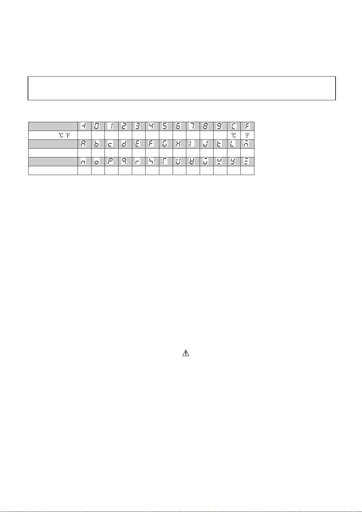
Characters used in this manual
Indication
Number, / -1 0 1 2 3 4 5 6 7 8 9
Indication
Alphabet A B C D E F G H I J K L M
Indication
Alphabet N O P Q R S T U V W X Y Z
Notes
• This instrument should be used in accordance with the specifications described in the manual.
If it is not used in accordance with the specifications, it may malfunction or cause fire.
• Be sure to follow the warnings, cautions and notices. If warnings are not observed, serious injury
or accidents may occur.
• The contents of this instruction manual are subject to change without notice.
• Care has been taken to assure that the contents of this instruction manual are correct, but if there
are any doubts, mistakes or questions, please inform our sales department.
• This instrument is designed to be installed in a control panel. If it is not, measures must be taken to
ensure that power terminals or other high voltage sections cannot be touched.
• Any unauthorized transfer or copying of this document, in part or in whole, is prohibited.
•
Panasonic Electric Works Co., Ltd.
as a result of using this product, including any indirect damage.
e
is not liable for any damage or secondary damage(s) incurred
Safety precautions
(Be sure to read these precautions before using our products.)
The safety precautions are classified into two categories: “Warning” and “Caution”.
Depending on circumstances, procedures indicated by Caution may have serious consequences,
so be sure to follow the directions for correct usage.
Warning
Procedures which may lead to dangerous conditions and cause death or serious injury,
if not carried out properly.
Procedures which may lead to dangerous conditions and cause superficial to medium injury
or physical damage or may degrade or damage the product, if not carried out properly.
2
Page 3
11..IInnssttaallllaattiioonnpprreeccaauuttiioonns
s
Caution
This instrument is intended to be used under the following environmental conditions
(IEC61010-1): Overvoltage category , Pollution degree 2
Ensure the mounting location corresponds to the following conditions:
• A minimum of dust, and an absence of corrosive gases
• No flammable or explosive gases
• No mechanical vibrations or shocks
• No exposure to direct sunlight, an ambient temperature of 0 to 50 (32 to 122 )
that does not change rapidly
• An ambient non-condensing humidity of 35 to 85%RH
• No large capacity electromagnetic switches or cables through which large current
is flowing
• No water, oil or chemicals or where the vapors of these substances can come into
contact with the unit
Note: Do not install this instrument near flammable material even though the case of this instrument
is made of flame-resistant resin.
Avoid setting this instrument directly on flammable material.
22..WWiirriinnggpprreeccaauuttiioonns
s
Caution
• Use the solderless terminal with an insulation sleeve in which an M3 screw fits, when wiring the
KT2.
• Tighten the terminal screw with the specified torque. If excessive force is applied to the screw
when tightening, the terminal screw or case may be damaged.
• Do not apply a commercial power source to the sensor which is connected to the input terminal
nor allow the power source to come into contact with the sensor.
• This controller does not have built-in power switch, circuit breaker or fuse.
It is necessary to install them near the controller.
(Recommended fuse: Time-lag fuse, rated voltage 250V AC, rated current 2A)
33..RRuunnnniinnggaannddmmaaiinntteennaanncceepprreeccaauuttiioonns
s
Warning
• It is recommended that the PID auto-tuning be performed on the trial run.
• Do not touch live terminals. This may cause electric shock or problems in operation.
• Turn the power supply to the instrument OFF before retightening the terminal and cleaning.
Working or touching the terminal with the power switched ON may result in severe injury or
death due to Electric Shock.
• Use a soft, dry cloth when cleaning the instrument.
(Alcohol based substances may tarnish or deface the unit)
• As the display section is vulnerable, do not strike or scratch it with a hard object.
3
Page 4

--- CONTENTS---
1. Model number
1.1 Model number ----------------------------------------------------------------------- 5
1.2 How to read the rated label ------------------------------------------------------ 5
2. Name and functions of the sections ------------------------------------- 5
3. Mounting to the control panel
3.1 Site selection ------------------------------------------------------------------------- 6
3.2 External dimensions ---------------------------------------------------------------- 6
3.3 Panel cutout -------------------------------------------------------------------------- 6
3.4 Mounting ------------------------------------------------------------------------------ 6
4. Wiring ------------------------------------------------------------------------------------- 7
5. Setup procedures
5.1 Setup procedures ------------------------------------------------------------------ 8
5.2 Initial setting ------------------------------------------------------------------------- 8
6. Setup
6.1 Main setting mode -----------------------------------------------------------------14
6.2 Sub setting mode ------------------------------------------------------------------16
6.3 Auxiliary function setting mode 1 ---------------------------------------------- 17
7. Running
7.1 Startrunning ------------------------------------------------------------------------ 18
7.2 MV (Control output manipulated variable) indication --------------------- 19
7.3 Control output OFF function ---------------------------------------------------- 19
7.4 Auto-tuning (AT) Perform/Cancel ---------------------------------------------- 19
8. Operation flowchart -------------------------------------------------------------- 20
9. PID auto-tuning -------------------------------------------------------------------- 22
10. Action explanation
10.1 OUT1 (Heating) action --------------------------------------------------------- 23
10.2 OUT1 (Heating) ON/OFF action --------------------------------------------- 23
10.3 A1, A2 action --------------------------------------------------------------------- 24
10.4 Heating/Cooling control action (Heating/Cooling control option) --- 24
10.5 Heating/Cooling control action (When setting dead band)
(Heating/Cooling control option) --------------------------------------------- 25
10.6 Heating/Cooling control action (When setting overlap band)
(Heating/Cooling control option) --------------------------------------------- 25
10.7 Timer action ----------------------------------------------------------------------- 25
11. Specifications
11.1 Standard specifications --------------------------------------------------------- 26
11.2 Optional specifications ---------------------------------------------------------- 28
12.Troubleshooting
12.1 Indication ---------------------------------------------------------------------------29
12.2 Key operation --------------------------------------------------------------------- 30
12.3 Control ------------------------------------------------------------------------------ 30
13. Character table ------------------------------------------------------------------- 31
4
Page 5
1. Model number
1
1.1 Model number
A K T 2 1 0
(1) (2) (3) (4) (5) (6)
(1) Supply voltage ---------------------- 1: 100 to 240V AC 2: 24V AC/DC
(2) Input type ----------------------------- 1: Multi-input (Thermocouple, RTD, DC current and DC voltage
can be selected by keypad)
(3) Control output (OUT1) ----------- 1: Relay contact 2: Non-contact voltage 3: DC current
(4)Alarm output ------------------------- 0: Not available (When both Healing/Cooling control and Serial
communication are selected)
1:A1 output or A2 output (However, if Healing/Cooling control
is selected, only A2 output is available. If Serial communication
is selected, only A1 output is available)
2:A1 output + A2 output (When neither Healing/Cooling control
nor Serial communication is selected)
(5) Heating/Cooling control (OUT2) output: 0: Not available 1: Relay contact
(6) Serial communication ------------- Blank: Not available 1: Applied
1.2 How to read the rated label
The rated label is attached to the case and the inner assembly.
(For case) (For inner assembly)
(Example)
Supply voltage: 100 to 240V AC
Multi-input
Relay contact output
A1 output + A2 output
Heating/Cooling control is not added
Serial communication is not added
(Fig. 1.2-1)
2
(Fig. 1.2-2)
1
: Model number,supply
voltage, input type, output
type, etc. are entered
2
: Lot number is entered.
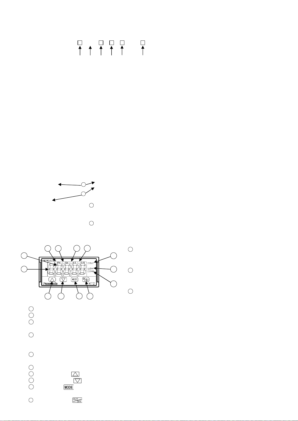
2. Name and functions of the sections
3 4 5 6
1
2
7
8
9
10 11
12
13
(Fig. 2-1)
4
SV indicator (green) : Lights when SV (main set value) is indicated.
5
AT indicator (yellow) : Flashes during AT (auto-tuning).
6
T/R indicator (yellow): Flashes during Serial communication.
(Lit while sending data, Unlit while receiving data)
7
OUT indicator (green): Lights when control output or OUT1 (Heating side, Heating/Cooling control
option) is ON. (For DC current output type, it flashes corresponding to the
manipulated variable in 0.25 second cycles)
8
EV1 indicator (red) : Lights when Event output 1 or OUT2 (Cooling side, Heating/Cooling control
option) is ON.
9
EV2 indicator (red) : Lights when Event output 2 is ON.
10
Increase key ( ) : Increases the numeric value.
11
Decrease key ( ) : Decreases the numeric value.
12
Mode key ( ) : Selects the setting mode or registers the set value.
(BypressingtheModekey, the set value or selectedvaluecanberegistered)
13
OUT/OFF key ( ) : The control output OUT/OFF or program control RUN/STOP can be switched.
1
PV/SV display (red): Indicates the PV (Process variable)
and SV (Main set value). During setting mode, characters
and set value of each setting item are indicated alternately.
2
MEMO/STEP display (green): Indicates memory number
during fixed value control. Indicates step number during
program control.
3
PV indicator (red): Lightswhen thePV(Process variable)
is indicated.
5
Page 6
3. Mounting to the control panel
47.6
36.5
44.8
21.6
23.8 (*)
24
48
10.6
98.5
101 (*)
3.1 Site selection
This instrument is intended to be used under the following environmental conditions
(IEC61010-1): Overvoltage category , Pollution degree 2
Ensure the mounting location corresponds to the following conditions:
• A minimum of dust, and an absence of corrosive gases
• No flammable or explosive gases
• No mechanical vibrations or shocks
• No exposure to direct sunlight, an ambient temperature of 0 to 50 (32 to 122 )
that does not change rapidly
• An ambient non-condensing humidity of 35 to 85%RH
• No large capacity electromagnetic switches or cables through which large current is flowing
• No water, oil or chemicals or where the vapors of these substances can come into contact
with the controller
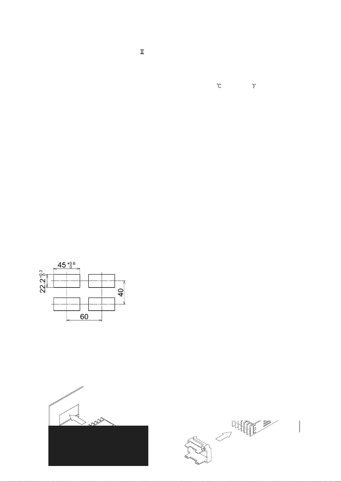
3.2 External dimensions (Unit: mm)
47.5 (*)
(*): When terminal cover is added
(Fig. 3.2-1)
3.3 Panel cutout (Unit: mm)
(Fig. 3.3-1)
3.4 Mounting
Mount the controller vertically so that dust and water do not enter, fulfilling the Dust-proof/Drip-proof
specification (IP66).
Mountable panel thickness: 1 to 10mm
(1) Insert the controller from the front side of the panel. (Fig. 3.4-1)
(2) Insert the mounting frame until 2 tips of the frame touch the panel. (Fig. 3.4-2)
(3) Tighten screws with 3/4 rotations upon the screw tips touching the panel.
(Fig.3.4-1) (Fig.3.4-2)
6
Page 7
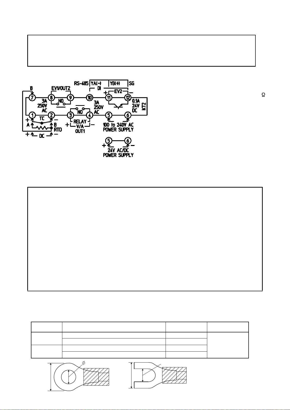
4. Wiring
5.8mm or less
Warning
Turn the power supply to the instrument off before wiring.
Working or touching the terminal with the power switched on may result in severe injury
or death due to Electric Shock.
• TC : Thermocouple input terminals
• RTD : RTD input terminals
• DC : DC current, DC voltage input terminals
For DC current input type, connect 50
shunt resistor (sold separately) between
input terminals.
• OUT1 : Control output or Heating output (Heating/
Cooling control option) terminals
• POWER SUPPLY: Power terminals
• EV1/OUT2: Event output 1 or Cooling output
(Heating/Coolingcontroloption) terminals
• EV2 : Event output 2 terminals
• DI : DI (Digital input) terminals
Three DI functions: SV1/SV2 external
(Fig. 4-1) selectionfunction,OUT/OFF(RUN/STOP)
external selection and Timer function
• RS-485: Serial communication terminals
Notice
• To extend a thermocouple’s lead wire,be sure to use a compensating lead wire in accordancewith
the sensor input specification.(Ifany other compensating lead wire is used, a temperature indication
error may be caused.)
• Use the 3-wire RTD which corresponds to the input specification of this controller.
• This controller does not have a built-in power switch, circuit breaker or fuse. Therefore, it is
necessary to install them in the circuit near the external controller.
(Recommended fuse: Time-lag fuse, rated voltage 250V AC, rated current 2A)
• When using a 24V DC for the power source, do not confuse polarity.
• When using a relay contact output type, externally use a relay according to the capacity of
the load to protect the built-in relay contact.
• When wiring, keep input wires (thermocouple, RTD, etc.) away from AC sources or load wires
to avoid external interference.
• Do not apply a commercial power source to the sensor connected to the input terminal nor
allow the power source to come into contact with the sensor.
Lead wire solderless terminal
Use a solderless terminal with an insulation sleeve in which an M3 screw fits as shown below.
The torque should be 0.63N•m.
Solderless
terminal
Y type
Round type
Manufacturer Model
Nichifu Terminal Industries CO., LTD. TMEV1.25Y-3
Japan Solderless Terminal MFG CO., LTD. VD1.25-B3A
Nichifu Terminal Industries CO., LTD. TMEV1.25-3
Japan Solderless Terminal MFG CO., LTD. V1.25-3
3.2mm
3.2mm
Tightening
torque
0.63N•m
5.8mm or less
(Fig. 4-2)
7
Page 8
5. Setup procedures
PV/SV display
5.1 Setup procedures
The setup procedures of this controller is shown below. Refer to each item for details.
(1) Initial setting : Set the Input type, Alarm type, etc. during Auxiliary function setting mode 2.
(If the users’ specification is the same as the default value of the KT2, initial
setting is not necessary for the controller.)
(2) Main setting mode: Set Step SV and Step time for Program control during Main setting mode.
Referto Chapter“6.Setup”.
(3) Sub setting mode : Set PID values, A1 setting, etc during Subsetting mode.
(If the users’ PID values are the same as the default value of the KT2, it is not
necessary to set them.) Refer to Chapter “6. Setup”.
(4) Auxiliary function setting mode 1: Set the Lock function, Communication conditions, etc. during
Auxiliary function setting mode 1. (If the users’ specification is the same as
the default value of the KT2, it is not necessary to set them.)
Run Refer to Chapter “6. Setup”.
5.2 Initial setting
Before using this controller, it is necessary to set up the Input type, Alarm type, Control action, etc.
according to the users’ conditions. This is an initial setting.
Default values are set as follows.
Input: K –200to1370 ,Alarm1(A1):Noalarmaction,Alarm2(A2):Noalarmaction,Reverse(Heating)action
If the users’ specification is the same as the default value of the KT2, initial setting is not necessary.
Proceed to Section “6.1 Main setting mode”.
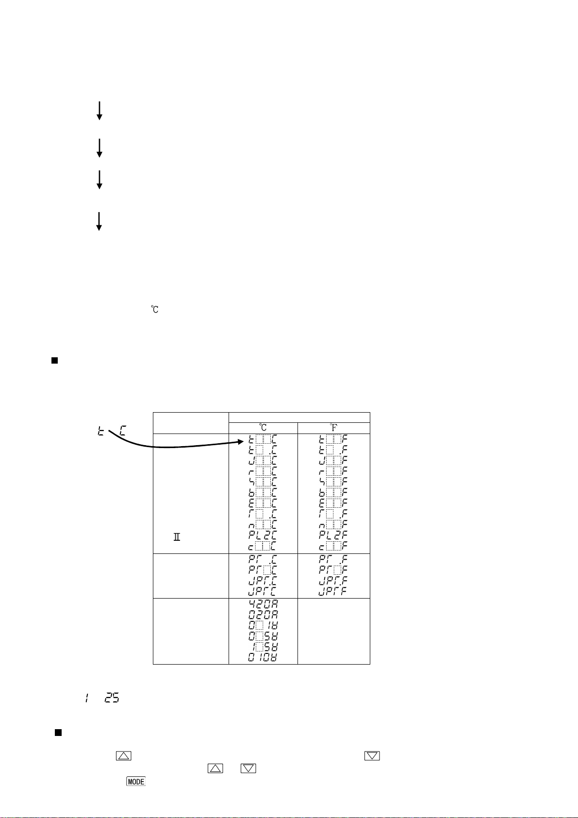
Turn the power supply to the instrument on.
For approx. 3 seconds after the power is turned on, the MEMO/STEP display is turned off and the PV/SV
display indicates sensor input characters and temperature unit. (Table 5.2-1)
During this time, all outputs and LED indicators are in an OFF status.
(Table 5.2-1)
Sensor input
K
J
R
S
B
E
T
N
PLC (W/Re5-26)
Pt100
JPt100
4 to 20mA DC
0 to 20mA DC
0 to 1V DC
0 to 5V DC
1 to 5V DC
0 to 10V DC
After that, the following is indicated.
The MEMO/STEP display indicates a memory number. The PV/SV display indicates an
input value (e.g. room temperature). This is the PV/SV display mode.
Basic operation for initial setting
Initial setting is conducted in Auxiliary function setup mode 2. To go to Auxiliary function setup mode 2,
press the key for approx. 3 seconds while holding down the key in the PV/SV display mode.
Setorselectthevalueswiththe or key.
Pressingthe keyregisters thevalues andgoes tothe nextitem.
8
Page 9
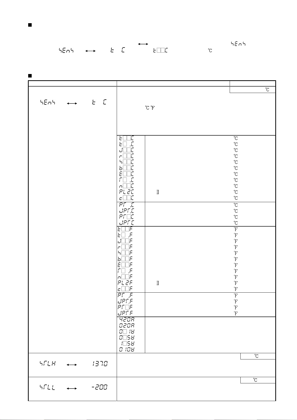
Display used for explaining setting items
Setting items (Section “5.2 Initial setting” and setting modes from Section 6.1 to 6.3) are explained as follows.
(e.g.) Input type selection
means that input type characters and selected
value (K –200 to 1370 ) are indicated in turn.
Auxiliary function setting mode 2
Display Item, Function, Setting range Default value
Input type selection K (-200 to 1370 )
• The input type can be selected from thermocouple (10 types),
RTD (2 types), DC current (2 types) and DC voltage (4 types).
The unit / can be selected as well.
• When changing the input from DC voltage to other inputs,
remove the sensor connected to this controller first, then
change for the input. If the input is changed with the
sensor connected, the input circuit may break.
:
K
:
:
J
:
R
:
S
:
B
:
E
:
T
:
N
:
PL:
C (W/Re5-26)
:
Pt100
:
JPt100
:
Pt100
:
JPt100
:
K
:
:
J
:
R
:
S
:
B
:
E
:
T
:
N
:
PL-
:
C (W/Re5-26)
:
Pt100
:
JPt100
:
Pt100
:
JPt100
:
4 to 20mA DC
:
0 to 20mA DC
:
0 to 1V DC
:
0 to 5V DC
:
1 to 5V DC
:
0 to 10V DC
Scaling high limit setting 1370
• Sets scaling high limit value.
• Setting range: Scaling low limit value to input range high
limit value
Scaling low limit setting -200
• Sets scaling low limit value.
• Setting range: Input range low limit value to scaling high limit
value
-200 to 1370
-199.9 to 400.0
-200 to 1000
0 to 1760
0 to 1760
0 to 1820
-200 to 800
-199.9 to 400.0
-200 to 1300
0 to 1390
0 to 2315
-199.9 to 850.0
-199.9 to 500.0
-200 to 850
-200 to 500
-320 to 2500
-199.9 to 750.0
-320 to 1800
0 to 3200
0 to 3200
0 to 3300
-320 to 1500
-199.9 to 750.0
-320 to 2300
0 to 2500
0 to 4200
-199.9 to 999.9
-199.9 to 900.0
-300 to 1500
-300 to 900
-1999 to 9999
-1999 to 9999
-1999 to 9999
-1999 to 9999
-1999 to 9999
-1999 to 9999
9
Page 10
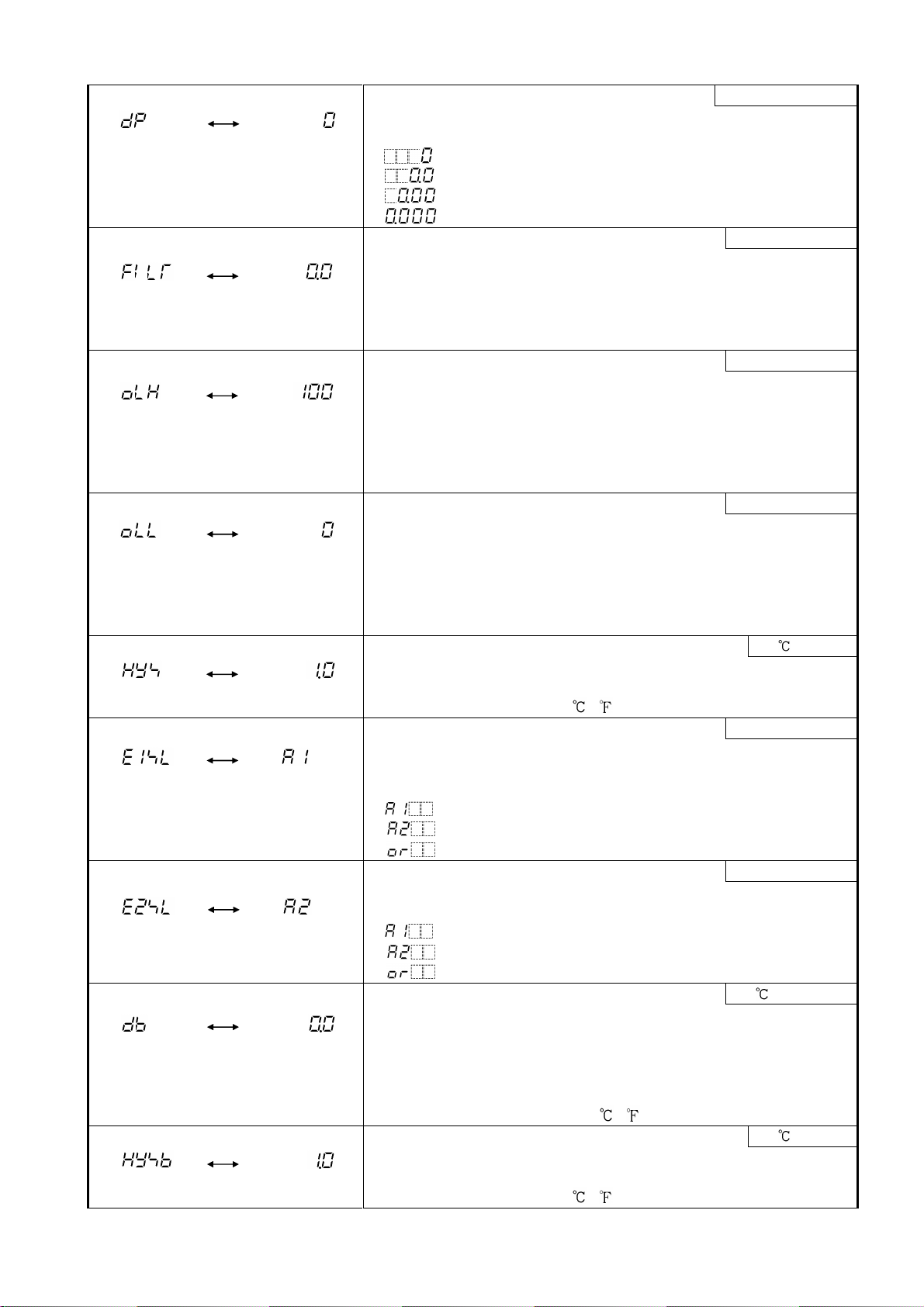
Decimal point place selection No decimal point
• Selects decimal point place.
• Available only for DC input
• : No decimal point
: 1 digit after decimal point
: 2 digits after decimal point
: 3 digits after decimal point
PV filter time constant setting 0.0 seconds
• Sets PV filter time constant.
Input fluctuation due to the noise can be reduced.
If the value is set too large, it affects control result due to the
delay of response.
• Setting range: 0.0 to 10.0 seconds
OUT1 (Heating) high limit setting 100%
• Sets OUT1 (Heating) high limit value.
Not available if OUT1 (Heating) is ON/OFF action
• If Heating/Cooling control option is added, OUT1 terminals are
used for Heating output terminals.
• Setting range: OUT1 (Heating) low limit value to 105%
(Setting higher than 100% is effective to DC current output type)
OUT1 (Heating) low limit setting 0%
• Sets OUT1 (Heating) low limit value.
Not available if OUT1 (Heating) is ON/OFF action
• If Heating/Cooling control option is added, OUT1 terminals are
used for Heating output terminals.
• Setting range: –5% to OUT1 (Heating) high limit value
(Setting less than 0% is effective to DC current output type)
OUT1(Heating)ON/OFF action hysteresis setting 1.0
• Sets ON/OFF action hysteresis for OUT1 (Heating).
• Available only when OUT1 (Heating) is ON/OFF action
• Setting range: 0.1 to 100.0 ( ), or 1 to 1000
EV1 output selection A1 output
• Selects a function for EV1 output terminals.
• Not available if Heating/Cooling control option is added, since
EV1 terminals are used for Cooling output terminals.
• :A1 output
:A2 output
: Common to A1 and A2 output
EV2 output selection A2 output
• Selects a function for EV2 output terminals.
• Not available if Serial communication option is added
• :A1 output
:A2 output
: Common to A1 and A2 output
Overlap band/Dead band setting 0.0
• Sets the overlap band or dead band for OUT1 (Heating side) and
OUT2 (Cooling side).
+ set value: Dead band
– set value: Overlap band
• Available only when the Heating/Cooling controloptionis added
• Setting range: –100.0 to 100.0 ( ), or 1 to 1000
OUT2 (Cooling) ON/OFF actionhysteresissetting 1.0
• Sets ON/OFF action hysteresis for OUT2 (Cooling side).
• Available only when the Heating/Cooling controloptionis added
• Setting range: 0.1 to 100.0 ( ), or 1 to 1000
10
Page 11

A1 type selection No alarm action
• Selects an A1 (Alarm 1) type.
• : No alarm action
: High limit alarm
: Low limit alarm
: High/Low limits alarm
: High/Low limit range alarm
: Process high alarm
: Process low alarm
: High limit alarm with standby
: Low limit alarm with standby
: High/Low limits alarm with standby
: Timer function
: Pattern end output
If Timer function is selected, Timer function works only
when Delay action type, Delay time and DI (digital input)
function are set or selected.
A2 type selection
No alarm action
• Selects an A2 (Alarm 2) type.
• Alarm type selection and default value are the same as those of
A1 type selection.
A1 hysteresis setting
1.0
• Sets hysteresis for A1.
• Not available if No alarm action, Timer function or Pattern end
output is selected during A1 type selection
• Setting range: 0.1 to 100.0 ( ), or 1 to 1000
A2 hysteresis setting
1.0
• Sets hysteresis for A2.
• Not available if No alarm action, Timer function or Pattern end
output is selected during A2 type selection
• Setting range: 0.1 to 100.0 ( ), or 1 to 1000
A1 action delayed timer setting
0 seconds
• Sets action delayed timer for A1.
When setting time has elapsed after the input enters the alarm
output range, the alarm is activated.
• Not available if No alarm action, Timer function or Pattern end
output is selected during A1 type selection
• Setting range: 0 to 9999 seconds
A2 action delayed timer setting
0 seconds
• Sets action delayed timer for A2.
When setting time has elapsed after the input enters the alarm
output range, the alarm is activated.
• Not available if No alarm action, Timer function or Pattern end
output is selected during A2 type selection
• Setting range: 0 to 9999 seconds
Alarm HOLD function selection
Alarm Not Holding
• Selects whether alarm HOLD function for A1 or A2 is used or
not used.
• This setting item is common to A1 and A2.
Not available if No alarm action, Timer function or Pattern end
output is selected during A1 or A2 type selection.
• :Alarm Not Holding
:Alarm Holding
11
Page 12

Delay action type selection
OFF delay
ON delay
• Selects a delay action type for Timer function.
• Available only when Timer function is selected during A1 or A2
type selection.
• : ON delay
: OFF delay
: ON/OFF delay
ON
(Contact Closed)
DI
(Digital
input)
OFF
(Contact Open)
ON
DLY
ON delay
ON/OFF
OFF
ON
OFF
DLY
ON
DLY
DLY
delay
OFF
DLY: Delay time setting
(Fig. 5.6-1)
Delay time setting
0 seconds
• Sets delay time for the Timer function.
• Available only when Timer function is selected during A1 or A2
type selection.
• Setting range: 0 to 9999 seconds
Direct/Reverse control action selection
Reverse (Heating)
• Selects Reverse (Heating) or Direct (Cooling) control action.
・ : Reverse (Heating) action
: Direct (Cooling) action
AT bias setting
20
• Sets bias value when performing auto-tuning.
See page 22 for PID auto-tuning.
• Not available for DC input
• Setting range: 0 to 50 (0 to 100 ) or 0.0 to 50.0 (0.0 to100.0 )
Setting item not used
This item is indicated when Serial communication option is added.
However, this cannot be used.
OUT/OFF key function selection
Control output
OUT/OFF function
• Selects whether OUT/OFF key is used for control output
OUT/OFF function (Fixed value control) or for program control
RUN/STOP function.
• : Control output OUT/OFF function (Fixed value control)
: Program control RUN/STOP function
Step time unit selection Hour:Minute
• Selects Step time unit for the program control function.
• Not available if control output OUT/OFF function (Fixed value
control) is selected during [OUT/OFF key function selection].
• : Hour:Minute
: Minute:Second
12
Page 13

DI (Digital input) function
Between DI terminals from Open to Closed: RUN (program
Between DI terminals from Closed to Open: STOP (program
selection
SV1/SV2 external selection
function
• Selects DI function whether it is used as SV1/SV2 external
selection function, OUT/OFF (RUN/STOP) external selection
function or Timer function.
If SV1/SV2 external selection function is selected;
SV1 or SV2 can be switched by external contact.
However, this function is not available if Program control
function is selected during OUT/OFF key function selection.
Between DI terminals Open: SV1
Between DI terminals Closed: SV2
If OUT/OFF(RUN/STOP)externalselection function is selected;
Control output OUT/OFF (Fixed value control) or Program
control RUN/STOP can be switched by external contact.
Fixed value control
Between DI terminals Open: OUT (Control allowed)
Between DI terminals Closed: OFF (Control prohibited,
control output OFF)
Program control
Program control RUN/STOP can be switched if the following
operation is conducted during program control standby.
control run)
control stop)
If DI terminal contact is changed from Closed to Open while
pattern end output is turned on after program controlended,
pattern end output is turned off.
Controller
status
DION
ContactClosed
DIOFF
ContactOpen
If Timer function is selected;
Timer counting starts by the external contact, and after the set
delay time has passed, the selected event output is turned on.
• Not available if Serial communication option is applied.
• : SV1/SV2 external selection function
Output status selection when input abnormal Output OFF
• Selects the output status of OUT1 and EV1/OUT2 when DC input
isoverscale orunderscale.See“Inputabnormalityindication” (p.28).
• Available only for DC current output type with DC input
• : OUT1outputs OFF(4mA) or OUT1(Heating)lowlimitvalue.
: OUT1 outputs a value between OFF(4mA) and ON(20mA),
Controller/Converter function selection Controller
• Selects whether to use the KT2 as a controller or a converter.
If theKT2isswitched from a convertertoa controller, control
parameters which were automatically set when converter
function was selected are maintained as they were. Therefore
correct the values whenusingthe KT2 as a controller.
• Available only for DC current output type
• : Controller
Standby mode
Contact Open
Standby mode
Programcontrolisperformed
whenthecontactischanged
fromOpentoClosed.
ProgramcontrolRUN
Contact Closed
Performsprogramcontrol.
Programcontrolstopswhen
thecontactis changedfrom
ClosedtoOpen.
ProgramcontrolSTOP
Contact Open
Stopsprogramcontrol.
: OUT/OFF(RUN/STOP) external selection function
: Timer function
EV1/OUT2: OFF
or outputs a value between OUT1(Heating) low limit value
and OUT1 (Heating) high limit value.
EV1/OUT2: ON
: Converter
13
Page 14

6. Setup
6.1 Main setting mode
To go to the main setting mode, press the key in the PV/SV display mode.
Set each setting item with the or key, and register the value with the key.
In the main setting mode, indicated setting items are different depending on the instrument status.
• Fixed value control
Setting items SV1 and SV2 will be indicated.
• Program control
Step SV and step time from Step 1 to Step 9 will be indicated.
Step number
200
0
(Fig.6.1-1)
1 2
C
C
1:00 2:00
Program control run
This program pattern shows that the
temperature rises to 200 for 1 hour
and stays at 200 for 2 hours.
In this case,
Step 1 SV: 200
Step 1 time (1 hour): 01:00
Step 2 SV: 200
Step 2 time (2 hours): 02:00
Display
Item, Function, Setting range Default value
SV1 (step 1 SV) setting 0
• Sets SV1 or step 1 SV.
• Scaling low limit value to Scaling high limit value
Step 1 time setting 00:00
• Sets step 1 time.
• Available only when program control function is selected during
OUT/OFF key function selection
• Setting range: 00:00 to 99:59
SV2 (step 2 SV) setting 0
• Sets SV2 or step 2 SV.
• Available when SV1/SV2 external selection function is
selected during DI (digital input) function selection or when
program control function is selected during OUT/OFF key
function selection.
• Scaling low limit value to Scaling high limit value
Step 2 time setting 00:00
• Sets step 2 time.
• Available only when program control function is selected during
OUT/OFF key function selection
• Setting range: 00:00 to 99:59
Step 3 SV setting 0
• Sets step 3 SV.
• Available only when program control function is selected during
OUT/OFF key function selection
• Scaling low limit value to Scaling high limit value
Step 3 time setting 00:00
• Sets step 3 time.
• Available only when program control function is selected during
OUT/OFF key function selection
• Setting range: 00:00 to 99:59
Step 4 SV setting 0
• Sets step 4 SV.
• Available only when program control function is selected during
OUT/OFF key function selection
• Scaling low limit value to Scaling high limit value
14
Page 15

Step 4 time setting 00:00
• Sets step 4 time.
• Available only when program control function is selected during
OUT/OFF key function selection
• Setting range: 00:00 to 99:59
Step 5 SV setting 0
• Sets step 5 SV.
• Available only when program control function is selected during
OUT/OFF key function selection
• Scaling low limit value to Scaling high limit value
Step 5 time setting 00:00
• Sets step 5 time.
• Available only when program control function is selected during
OUT/OFF key function selection
• Setting range: 00:00 to 99:59
Step 6 SV setting 0
• Sets step 6 SV.
• Available only when program control function is selected during
OUT/OFF key function selection
• Scaling low limit value to Scaling high limit value
Step 6 time setting 00:00
• Sets step 6 time.
• Available only when program control function is selected during
OUT/OFF key function selection
• Setting range: 00:00 to 99:59
Step 7 SV setting 0
• Sets step 7 SV.
• Available only when program control function is selected during
OUT/OFF key function selection
• Scaling low limit value to Scaling high limit value
Step 7 time setting 00:00
• Sets step 7 time.
• Available only when program control function is selected during
OUT/OFF key function selection
• Setting range: 00:00 to 99:59
Step 8 SV setting 0
• Sets step 8 SV.
• Available only when program control function is selected during
OUT/OFF key function selection
• Scaling low limit value to Scaling high limit value
Step 8 time setting 00:00
• Sets step 8 time.
• Available only when program control function is selected during
OUT/OFF key function selection
• Setting range: 00:00 to 99:59
Step 9 SV setting 0
• Sets step 9 SV.
• Available only when program control function is selected during
OUT/OFF key function selection
• Scaling low limit value to Scaling high limit value
Step 9 time setting 00:00
• Sets step 9 time.
• Available only when program control function is selected during
OUT/OFF key function selection
• Setting range: 00:00 to 99:59
15
Page 16

6.2 Sub setting mode
To go to the Sub settingmode,press the key whileholding downthe key in the PV/SVdisplay mode.
Set each setting item with the or key, and register the value with the key.
Display Item, Function, Setting range Default value
AT (Auto-tuning) selection ATCancel
• Selects auto-tuning Perform/Cancel.
Not available for program control standby status and for
control actions other than PID action.
• : AT Cancel : AT Perform
OUT1 (Heating) proportional band setting 2.5%
• Sets the proportional band for OUT1 (Heating side).
• ON/OFF action when set to 0.0.
• Setting range: 0.0 to 110.0%
OUT2 (Cooling) proportional band setting 1.0 times
• Sets the proportional band for OUT2 (cooling side).
• ON/OFF action when set to 0.0.
• Not available if Heating/Cooling control option is not added or
if OUT1 (Heating side) is ON/OFF action
• Settingrange: 0.0 to 10.0 times OUT1 (Heating) proportional band
OUT1 (Heating) integral time setting 200 seconds
• Sets the integral time.
• Setting the value to 0 disables the function. (PD action)
• Not available if OUT1 (Heating) is ON/OFF action
• Setting range: 0 to 1000 seconds
OUT1 (Heating) derivative time setting 50 seconds
• Sets the derivative time.
• Setting the value to 0 disables the function. (PI action)
• Not available if OUT1 (Heating) is ON/OFF action
• Setting range: 0 to 300 seconds
ARW setting 50%
• Sets the ARW (anti-reset windup).
• Available only for PID action.
• Setting range: 0 to 100%
OUT1 (Heating) proportional cycle setting
• Sets OUT1 (Heating) proportional cycle.
• Sets the proportional cycle.
• Not available for DC current output type or
if OUT1 (Heating) is ON/OFF action.
• Setting range: 1 to 120 seconds
OUT2 (Cooling) proportional cycle setting 30 seconds
• Sets OUT2 (Cooling) proportional cycle.
• Not available if Heating/Cooling control option is not added or
if cooling output is ON/OFF action.
• Setting range: 1 to 120 seconds
Manual reset setting 0.0
• Sets reset value manually.
• Available only for P or PD action.
• Proportional band converted value (For DC input, the
placement of the decimal point follows the selection.)
A1 value setting 0
• SetsA1 action point. Setting the value to 0 or 0.0 disablesthe
function (except processhigh alarm and process low alarm).
• Not available if No alarm action, Timer function or Pattern end
output is selected during A1 type selection
• Setting range: See (Table 6.2-1).
A2 value setting 0
• SetsA2 action point. Setting the valueto 0 or 0.0 disables the
function (except processhigh alarm and process low alarm).
• Not available if No alarm action, Timer function or Pattern end
output is selected during A2 type selection
• Setting range: See (Table 6.2-1).
Relay contact:30sec
Non-contact
voltage: 3sec
DC current: Not
available
16
Page 17

(Table 6.2-1)
setting items such as the
For the inputs
with a
Alarm type Setting range
High limit alarm -(Scaling span) to Scaling span
Low limit alarm -(Scaling span) to Scaling span
High/Low limits alarm 0 to Scaling span
High/Low limit range alarm 0 to Scaling span
Process high alarm Scaling low limit to Scaling high limit value
Process low alarm Scaling low limit to Scaling high limit value
High limit alarm with standby - (Scaling span) to Scaling span
Low limit alarm with standby - (Scaling span) to Scaling span
High/Low limits alarm w/standby 0 to Scaling span
6.3 Auxiliary function setting mode 1
To go to Auxiliary function setting mode 1, press the key for approx. 3 seconds while holding down
the key in the PV/SV display mode.
Set each setting item with the or key, and register the value with the key.
Display Item, Function, Setting range Default value
PV/SV indication selection PV indication
• PV indication ( ) or SV indication ( ) can be selected.
PV indication with key, SV indication with the key
• During input burnout, the PV/SV display flashes " " or
" " even if SV is indicated on the display.
Set value lock selection Unlock
• Locks the set values to prevent setting errors.
The setting item to be locked depends on the selection.
• When Lock 1 or Lock 2 is selected, PIDAuto- tuning cannot be
carried out.
• Becausethereislimitednon-volatilememory,besuretoselectLock 3
whenthesetvalueischangedfrequentlyviacommunication function.
• (Unlock):All set values can be changed.
(Lock 1): None of the set values can be changed.
(Lock 2): SV1 and SV2 can be changed during fixed
valuecontrol. StepSV andstep timecan be changed during
program control. Othersettingitemscannot be changed.
(Lock 3): All set values except input type and Controller/
Converter function can be changed. However, changed
values revert to their previous value after the power is turned
offbecause theyarenotsaved inthenon-volatilememory.
(If the valueset by the communication functionis the sameas
the value before thesetting, thevalue willnot be written in the
non-volatile memory.) Do not change any setting item in
Auxiliaryfunction setting mode 2. If anyitem in the mode
is changed, it will affect other
SVandAlarmvalue.
Sensor correction setting 0.0
• Sets the correction value for the sensor.
PV aftersensorcorrection =CurrentPV + (Sensorcorrection value)
• Setting range: –100.0 to 100.0 ( ) DC input: –1000 to 1000
Communication protocol selection ModbusASCII
• Selects the communication protocol.
• Available only when the Serial communication option is applied.
• : Unavailable
: ModbusASCII mode : Modbus RTU mode
Instrument number setting 0
• Sets the instrument number individually to each instrument when
communicating by connecting plural instruments in Serial
communication.
• Available only when Serial communication option is added.
• Settingrange: 0 to 95(However,numberofconnectableunits: Max. 31 units)
Communication speed selection 9600bps
• Selects a communication speed to be equal to the speed of the
host computer.
• Available only when Serial communication option is added.
• : 2400bps : 4800bps
: 9600bps : 19200bps
decimal point, the
negative low limit
value is -199.9, and
the positive high limit
value is 999.9.
All alarm actions
except for the
Process alarm are a
deviation setting
from theSV (mainset
value).
17
Page 18

7. Running
7.1 Start running.
After the controller is mounted to the control panel and wiring is completed, operate the unit following the
procedures below.
(1) Turn the power supply to the KT2 ON.
For approx. 3sec after the power is switched ON, the sensor input characters and the temperature unit
are indicated on the PV/SV display. See (Table 5.2-1) on page 8.
During this time, all outputs and LED indicators are in an OFF status.
After that, control starts indicating the following depending on the controller status.
• Fixed value control status
Control starts indicating memory number on the MEMO/STEP display and PV (process variable) or SV
(main set value) on the PV/SV display. (If PV indication is selected during PV/SV indication selection,
PV is indicated. If SV indication is selected during PV/SV indication selection, SV is indicated.)
• Program control standby status
The MEMO/STEP display is turned off, and the PV/SV display indicates input value or " ".
(If PV indication is selected during PV/SV indication selection, PV is indicated. If SV indication
is selected during PV/SV indication selection, " " is indicated.)
• Program control run status
The MEMO/STEP display indicates step number,and the PV/SV display indicates input value or current
step temperature. (If PV indication is selected during PV/SV indication selection, PV is indicated.
If SV indication is selected during PV/SV indication selection, current step temperature is indicated.)
• When control output OFF function is working;
The MEMO/STEP display is turned off, and the PV/SV display indicates " ".
(2) Input each set value.
Input each set value, referring to “6. Setup”.
(3) Turn the load circuit power ON.
The controller starts as follows depending on the setting.
• Fixed value control
Control starts so as to keep the control target at the SV.
• Program control
Program control run
To performprogramcontrolrun,pressthe key. At this timethe programcontrol starts withPV start.
PV start: When the program control starts, SV and step time are advanced to the PV,then the
program control is performed.
(e.g.)PV is assumedto be 100 in the programpattern of Section“6.1 Mainsettingmode”.
If the program control is performed, the step SV advances from 0 to 100 , and the step
time also advances from 1:00 to 0:30.
Program control stop
To stop program control, press the key for approx. 1 second. The program control stops, and
the controller reverts to the program control standby mode.
Action after power is restored
If power failure occurs during the program control run, the control resumes from the point at which
power failure occurred.
If power failure occurs during program control standby mode, the control resumes from the program
control standby mode.
Progressingtimeerrorafterpoweris restored:Within 1 minuteregardless of steptimeunit
• Converter
In the case of DC current output type, each input value (thermocouple, RTD, DC current, DC voltage)
is converted to 4 to 20mA DC and outputted.
Input/output response is approx. 1 second.
When using an alarm action, select Process alarm during A1, A2 type selection.
18
Page 19

7.2 MV (Control output manipulated variable) indication
To indicate MV, hold down the key for approx. 3 seconds in the PV/SV display mode.
Keep pressing the key until MV appears, though SV1 (step 1 SV) setting item appears during
the process.
PV/SV display mode
Hold down the key for approx. 3 seconds.
Keep pressing the key until MV appears, though SV1 (step 1 SV)
setting item appears during the process.
(For approx.3sec)
MV (Control output manipulated variable) indication
The MEMO/STEP display indicates a memory number during fixed
value control and a step number during program control.
The PV/SV display indicates MV.
Flashes While MV is being indicated, the 1st decimal point from the right flashes
in 0.5 second cycles.
To release MV indication function, press the key again or turn the
power supply to the KT2 OFF,then ON.
7.3 Control output OFF function
This is a function to pause the control action or to turn the control output of the unused instrument of the
plural units OFF even if the power to the instrument is supplied.
To turn the control output OFF, press the key for approx. 1 second in the PV/SV display mode.
PV/SV display mode
Press the key for approx. 1 second.
(For approx. 1sec)
Control output OFF
The MEMO/STEP display is switched off and the PV/SV display
indicates . Once the control output OFF function is enabled,
(For approx.1sec) the function cannot be released even if the power to the instrument
is turned OFF and ON again.
To cancel the function, press the key again for approx. 1 second.
7.4 Auto-tuning (AT) Perform/Cancel
Auto-tuning Perform/Cancel can be selected during AT selection in the Sub setting mode.
PV/SV display mode
Press the key while holding down the key.
+
AT selection in the Sub setting mode
SelectAuto-tuning Perform ( ) with the key
and Auto-tuning Cancel ( ) with the key, then
press the key.
The ATindicator flashes while performing auto-tuning.
If Auto-tuning is cancelled during the process, P, I, D, ARW
values return to the previous values.
If PID auto-tuning does not finish in 4 hours after starting,
PID auto-tuning is cancelled automatically.
19
Page 20

8. Operation flowchart
PV/SV display mode
PV/SV display.
Alarm 1 (A1) setting procedures
reset it.
[A
uxiliary function setting mode 1]
[Main setting mode]
Explanation of key
Character indication
PV indication when SV is
Automatically
selected, and vice versa
MV indication
Flashes
returns 2sec later.
Press the key.
Press the key.
(Fixedvalue control)
(In the case of Program control standby)
PV indication:The MEMO/STEPdisplayis
SV indication: is indicated.
unlit. Only PV is indicated.
Press the key
for 1 second.
Press the key.
Control output OFF
(Fixed value control)
Program control RUN
(Program control)
Press the key.
SV1
(Step 1 SV)
MEMO/STEP
PV/SV , SV1
Step 1 time
MEMO/STEP
PV/SV , Set value
SV2
(Step 2 SV)
MEMO/STEP
PV/SV , SV2
Step 2 time
MEMO/STEP
PV/SV , Set value
Step 3 SV
MEMO/STEP
PV/SV , Step 3 SV
Step 3 time
MEMO/STEP
PV/SV , Set value
Each time
the key
is pressed,
the setting
item is
switched.
Set SV
and time
for the
necessary
step.
Step 9 SV
MEMO/STEP
PV/SV , Step 9 SV
Step 9 time
MEMO/STEP
PV/SV , Set value
Reverts to the
Press the key
for 3 seconds.
Press the key while holding down the key.
[Sub setting mode]
AT
PV/SV , Selection
OUT1 (Heating)
proportional band
PV/SV , Set value
OUT2 (Cooling)
proportional band
PV/SV , Set value
OUT1 (Heating)
integral time
PV/SV , Set value
OUT1 (Heating)
derivative time
PV/SV , Set value
ARW
PV/SV , Set value
OUT1 (Heating)
proportional cycle
PV/SV , Set value
OUT2 (Cooling)
proportional cycle
PV/SV , Set value
Manual reset
PV/SV , Set value
(5)
A1 value
PV/SV , Set value
A2 value
PV/SV , Set value
Reverts to the PV/SV display.
• If ATis cancelled during the process,
PID values return to previous values.
• Set the value with the , keys.
• ON/OFF action when set to 0.0
• Set the value with the , keys.
• Not available when OUT1 is ON/OFF
action
• Set the value with the , keys.
• Setting the value to 0 disables the
function.
• Set the value with the , keys.
• Setting the value to 0 disables the
function.
• Set the value with the , keys.
• Available only for PID action
• Set the value with the , keys.
• Not available for DC current output
type or if OUT1 is ON/OFF action.
• Set the value with the , keys.
• Not available if OUT2 is ON/OFF
action.
• Set the value with the , keys.
• Available only for P and PD action.
• Set the value with the , keys.
• Not available if , or
is selected during A1 type
selection.
• Set the value with the , keys.
• Not available if , or
is selected during A2 type
selection.
Press the key
for 1 second.
Press the while holding down the for 3sec.
PV/SV indication
PV/SV or
Set value lock
PV/SV ,
Selection
Sensor correction
PV/SV , Set value
Communication protocol
PV/SV , Selection
Instrument number
PV/SV , Set value
Communication speed
PV/SV , Selection
• Select PV or SV with the ,
keys.
• Make a selection with the ,
keys.
• If Lock 1 or Lock 2 is selected, AT
does not work.
• Be sure to select Lock 3 when
using Serial communication.
• Set the value with the ,
keys.
• Make a selection with the ,
keys.
• Set the value with the ,
keys.
• Make a selection with the ,
keys.
Reverts to the PV/SV display.
• : This means that if the key is pressed, the set
value is saved, and the controller proceeds to the
next setting item.
• If the key is pressed for approx. 3sec, the controller
reverts to the PV/SV display mode from any mode.
• Characters and set (selected) value of the setting item are
indicated on the PV/SV display alternately.
• Setting items with dotted lines are optional and they appear
only when the options are added.
(Numbers(1)to (5) are indicatedontheflowchart.)
(1) Select an alarm type during [A1 type selection].
[If , or is selected, (2) to (5)
are not indicated.]
(2) Set A1 hysteresis during [A1 hysteresis setting].
(3) Set A1 action delayed timer during [A1 action delayed
timer].
(If input enters alarm action range and setting time has
elapsed, the alarm is activated.)
(4) Select if the alarm output is held or not during [Alarm
HOLD function selection] (common to A1, A2).
(5) Set A1 action point during [A1 value setting].
[Note] If an alarm type is changed, the alarm value
becomes 0 (0.0). Therefore it is necessary to
20
Page 21

(2)
Input type (Character indication) and range
[Auxiliary function setting mode 2]
(4)
: K -200 to 1370
: -199.9 to 400.0
: J -200 to 1000
: R 0 to 1760
: S 0 to 1760
: B 0 to 1820
: E -200 to 800
: T -199.9 to 400.0
: N -200 to 1300
: PL- 0 to 1390
: C(W/Re5-26) 0 to 2315
: Pt100 -199.9 to 850.0
: JPt100 -199.9 to 500.0
: Pt100 -200 to 850
: JPt100 -200 to 500
: 4 to 20mA DC -1999 to 9999
: 0 to 20mA DC -1999 to 9999
Press key for 3sec while holding down the key.
: K -320 to 2500
: -199.9 to 750.0
: J -320 to 1800
: R 0 to 3200
: S 0 to 3200
: B 0 to 3300
: E -320 to 1500
: T -199.9 to 750.0
: N -320 to 2300
: PL- 0 to 2500
: C(W/Re5-26) 0 to 4200
: Pt100 -199.9 to 999.9
: JPt100 -199.9 to 900.0
: Pt100 -300 to 1500
: JPt100 -300 to 900
: 0 to 1V DC -1999 to 9999
: 0 to 5V DC -1999 to 9999
: 1 to 5V DC -1999 to 9999
: 0 to 10V DC -1999 to 9999
Alarm type
(Highlimitalarm):The alarm actionis a deviationsettingfrom the SV.
Thealarm is activated if the input value reaches the high limit alarm value.
(Low limit alarm): The alarm action is a deviation setting from the SV. The
alarm is activated if the input value goes under the low limit alarm value.
(High/Low limits alarm): Combines High limit and Low limit alarm actions. When
input value reaches high limit alarm value or goes under the low limit alarm
value, the alarm is activated.
(High/Low limit range alarm): When input value is between the high limit alarm
value and low limit alarm value, the alarm is activated.
(Process high alarm), (Process low alarm): Within the scale range
of the controller, alarm action points can be set at random and if the input
reaches the randomly set action point, the alarm is activated.
(High limit alarm with standby), (Low limit alarm with standby)
(High/Low limits alarm with standby)
When the power to the controller is turned on, even if the input enters the
alarm action range, the alarm is not activated. (If the controller is allowed
to keep running, once the input exceeds the alarm action point, the standby
function will be released.)
(Timer function): If external signal enters, timer counting starts, and the action
selected during Delay action type selection is outputted after the set delay
time has elapsed.
(Pattern end output): When the program ends normally, pattern end output is
turned on. The output is maintained until it is released with the key.
Input type
PV/SV , Selection
Scaling high limit
PV/SV , Set value
Scaling low limit
PV/SV , Set value
Decimal point place
PV/SV , Selection
PV filter time constant
PV/SV , Set value
OUT1(Heating)high limit
PV/SV , Set value
OUT1(Heating)lowlimit
PV/SV , Set value
OUT1(Heating)
ON/OFF actionhysteresis
PV/SV , Set value
EV1 output
PV/SV , Selection
EV2 output
PV/SV , Selection
Overlap/Dead band
PV/SV , Set value
OUT2 (Cooling)
ON/OFF actionhysteresis
PV/SV ,Set value
(1)
A1 type
PV/SV , Selection
A2 type
PV/SV , Selection
A1 hysteresis
PV/SV , Set value
A2 hysteresis
PV/SV , Set value
• Make a selection with the , keys.
• Default value:
• Set the value with the , keys.
• Default value: 1370
• Set the value with the , keys.
• Default value: -200
• Make a selection with the , keys.
• Available only for DC input
• Set the value with the , keys.
• Set the value with the , keys.
• Not available if OUT1 is ON/OFF action
• Set the value with the , keys.
• Not available if OUT1 is ON/OFF action
• Set the value with the , keys.
• Available only when OUT1 is ON/OFF action
• Make a selection with the , keys.
• Not availableif Heat/Cool controloptionisadded
• Make a selection with the , keys.
• Not availableif Serialcommunication optionis added
• Set the value with the , keys.
• Availableonlywhen Heat/Cool controloptionis added
• Set the value with the , keys.
• Available when Heat/Coolcontroloption is added
and when OUT2 is ON/OFF action
• Make a selection with the , keys.
• Default value:
• Make a selection with the , keys.
• Default value:
• Set the value with the , keys.
• Not available if , or
is selected during A1 type selection
• Set the value with the , keys.
• Not available if , or
is selected during A2 type selection
(3)
A1 action delayed
timer
PV/SV , Set value
A2 action delayed
timer
PV/SV , Set value
Alarm HOLD function
PV/SV , Selection
Delay action type
selection
PV/SV , Selection
Delay time
PV/SV , Set value
Direct/Reverse control
PV/SV , Selection
ATbias
PV/SV , Set value
Setting item not used
PV/SV , Set value
OUT/OFF key function
PV/SV , Selection
Step time unit
PV/SV , Selection
DI (Digital input) function
PV/SV , Selection
Output status selection
when input abnormal
PV/SV , Selection
Controller/Converter
PV/SV , Selection
Reverts to the PV/SV display.
• Set the value with the , keys.
• Not available if , or
is selected during A1 type selection
• Set the value with the , keys.
• Not available if , or
is selected during A2 type selection
• Make a selection with the , keys.
• Common setting item forA1 andA2
Not available if , or
is selected during A1 or A2 type selection.
• Make a selection with the , keys.
• Available only when is selected during
A1 orA2 type selection.
• Set the value with the , keys.
• Available only when is selected during
A1 or A2 type selection.
• Make a selection with the , keys.
• Default value: (Reverse control action)
• Set the value with the , keys.
• Not available for DC input.
• Do not set this item even if is indicated
on the PV/SV display.
• Make a selection with the , keys.
• Selects fixed value control or program control.
• Make a selection with the , keys.
• Not available if is selected during
OUT/OFF key function selection
• Make a selection with the , keys.
•Not available ifSerialcommunicationoptionisadded
• Make a selection with the , keys.
• Available only for DC current output type with
DC input
• Make a selection with the , keys.
• Available only for DC current output type
21
Page 22

9. PID auto-tuning
In order to set each value of P, I, D and ARW automatically, the auto-tuning process should be made to
fluctuate to obtain an optimal value.
Notice
• Perform auto-tuning during trial run.
• During auto-tuning, none of the setting items can be set.
• If auto-tuning starts during program control run, auto-tuning performs with SV at which auto-tuning
starts. The step time does not progress until auto-tuning ends.
• If power failure occurs during auto-tuning, auto-tuning stops.
• For DC input, theAT processwillfluctuatearoundthe SV for conditionsof (A),(B) and (C)below.
• Sometimes the auto-tuning process will not fluctuate if auto-tuning is performed at or near room
temperature. Therefore auto-tuning might not finish normally.
(A) In the case of a large difference between the SV and processing temperature as the
temperature is rising
When AT bias is set to 20 , the ATprocess will fluctuate at the temperature 20 lower than the SV.
Temperature 20 lower than
the SV
SV
(4)
Temperature
AT starting point
(1)
(2) (3)
(B) In the case of a stable control
The AT process will fluctuate around the SV.
SV
Temperature
AT starting point
(1)
(2)
(1) Calculating PID constant
(2) PID constant calculated
(3) Controlled by the PID constant
set by auto-tuning.
(4) AT bias value
Time
(Fig. 9-1)
(1) Calculating PID constant
(2) PID constant calculated
(3) Controlled by the PID constant
set by auto-tuning.
Time
(Fig. 9-2)
(3)
(C) In the case of a large difference between the SV and processing temperature as the
temperature is falling
When AT bias is set to 20 , the AT process will fluctuate at the temperature 20 higher than
the SV.
Temperature 20 higher than
Temperature
SV
the SV
(4)
AT starting point
(1)
(2)
Time
(3)
(1) Calculating PID constant
(2) PID constant calculated
(3) Controlled by the PID constant
set by auto-tuning.
(4) AT bias value
(Fig. 9-3)
22
Page 23

10. Action explanation
10.1 OUT1 (Heating) action
Heating (Reverse) action Cooling (Direct) action
Control
action
Relay contact
output
(OUT1)
Non-contact
voltage output
(OUT1)
DC current
output
(OUT1)
Indicator
(OUT) Green
Proportional band
ON
OFF
SV setting
3
4
Cycle action is performed according to deviation
+
3
12V DC
4
Cycle action is performed according to deviation Cycle action is performed according to deviation
+
3
20mA DC 20 to 4mA DC
4
Changes continuously according to deviation
Lit Unlit
3
4
3
+ +
12/0V DC
4
3
4
3
4
3
0V DC
4
3
4mA DC
4
Unlit
3
4
Cycle action is performed according to deviation
+ +
3
0V DC 12V DC
4
+++
3
4mA DC
4
Changes continuously according to deviation
Proportional band
SV setting
3
4
3
0/12V DC
4
3
4 to 20mA DC
4
3
4
+
3
4
++
3
20mA DC
4
ON
OFF
Lit
: Acts ON or OFF.
10.2 OUT1 (Heating) ON/OFF action
Heating (Reverse) action Cooling (Direct) action
Hysteresis
Control
ON
action
OFF
Relay contact
output
(OUT1)
Non-contact
voltage output
(OUT1)
DC current
output
(OUT1)
3
4
+
3
4
+ +
3
20mA DC
4
SV setting
3
4
3
+
0V DC12V DC
4
3
4mA DC
4
Hysteresis
SV setting
3
4
+
3
0V DC 12VDC
4
3
+
4mA DC
4
3
4
+
3
4
3
+
20mA DC
4
ON
OFF
Indicator
(OUT) Green
: Acts ON or OFF.
Lit
23
Unlit
LitUnlit
Page 24

10.3 A1, A2 action
High limit alarm
A1 hysteresis
A1 hysteresis
Low limit alarm
High/Low limits alarm
A1 hysteresis
Alarm
action
Alarm
action
Alarm
action
ON
OFF
ON
OFF
ON
OFF
A1 set point
High/Low limit range alarm
A1 set point A1 set point
High limit alarm with standby High/Low limits alarm with standbyLow limit alarm with standby
A1 set point
SV
setting
SV
setting
SV
setting
+ A1 set point
A1 hysteresis A1 hysteresis A1 hysteresis
A1 set point
A1 hysteresis A1 hysteresis
+ A1 set point
ON
OFF
A1 set point SV
ON
OFF
ON
OFF
A1 set point
+A1 set point
setting
Process high alarm
A1 set point
+ A1 set point
SV
setting
ON
OFF
A1 set point
ON
OFF
ON
OFF
A1 set point SV
SV
setting
Process low alarm
setting
: Standby functions in this section.
EV1 indicator lights up when terminals 8 and 9 are connected, and goes off when between
them are disconnected.
EV2 indicator lights up when terminals 11 and 12 are connected, and goes off when between
them are disconnected.
A1 set point
A1 hysteresis
A1 set point
10.4 Heating/Cooling control action (Heating/Cooling control option)
Heating P-band (Cooling P-band)
Control action
Relay contact
output
(OUT1)
Non-contact
voltage output
(OUT1)
DC current
output
(OUT1)
Relay contact
output
(EV1/OUT2)
Indicator
(OUT)
Green
Indicator
(EV1)
Yellow
: Acts ON (lit) or OFF (unlit).
: Represents Heating control action.
: Represents Cooling control action.
ON
Heaing
action
(Cooling
action)
OFF
SV setting
3
4
3
4
3
4
Cycle action is performed according to deviation.
+
3
3
+
+
3
12V DC 12/0V DC 0V DC
4
-
4
-
4
-
Cycle action is performed according to deviation.
3
+
20mA DC
4
-
3
+
20 to 4mA DC
4
-
+
-
3
4mA DC
4
Changes continuously according to deviation.
8
9
8
9
Cycle action is performed according to deviation.
Lit
Unlit Lit
24
ON
OFF
8
9
Unlit
Page 25

10.5 Heating/Cooling control action (When setting dead band) (Heating/Cooling control option)
Control action
Relay contact
output
(OUT1)
Non-contact
voltage output
(OUT1)
DC current
output
(OUT1)
Relay contact
output
(EV1/OUT2)
Indicator
(OUT) Green
Indicator
(EV1) Yellow
Heating P-band
ON
Heatng
action
OFF
SV setting
3
4
Cycle action is performed according to deviation.
3
+
12V DC 12/0V DC
4
-
Cycle action is performed according to deviation.
3
+
20mA DC
-
4
Changes continuously according to deviation.
Lit
Unlit
3
4
3
+
4
-
+
3
20 to 4mA DC
-
4
Dead band (Cooling P-band)
(Cooling
action)
3
4
3
+
0V DC
4
-
3
+
4mA DC
-
4
8 8
9
Cycle action is performed according to deviation.
8
9
9
Unlit
ON
OFF
Lit
: Acts ON (lit) or OFF (unlit).
: Represents Heating control action.
: Represents Cooling control action.
10.6 Heating/Cooling control action (When setting overlap 10.7 Timer action
band) (Heating/Cooling control option)
ON
(Contact Closed)
OFF
(Contact Open)
ON
OFF
ON
OFF
ON
OFF
DLY
DLY
DLY: Delay time setting
Control action
Relay contact
output
(OUT1)
Non-contact
voltage output
(OUT1)
DC current
output
(OUT1)
Relay contact
output
(EV1/OUT2)
Indicator
(OUT) Green
Indicator
(EV1) Yellow
: Acts ON (lit) or OFF (unlit).
: Represents Heating control action.
: Represents Cooling control action.
Heating P-band
Cooling P-band
ON
Heating
action
OFF
3
4
Cycle action is performed according to deviation.
3
+
12V DC 12/0V DC
4
-
Cycle action is performed according to deviation.
3
+
20mA DC
-
4
Changes continuously according to deviation.
8
9
Cycle action is performed according to deviation.
Lit
Unlit
Overlap
band
SV setting
3
4
3
+
4
-
+
3
20 to 4mA DC
-
4
8
9
+
-
+
-
(Cooling
action)
3
4
3
0V DC
4
3
4mA DC
4
DI
(Digital
input)
ON
ON delay
OFF
OFF delay
ON/OFF
delay
8
9
Unlit
Lit
DLY
DLY
25
Page 26

11. Specifications
11.1 Standard specifications
Mounting : Flush
Setting : Input system using membrane sheet key
Display PV/SVdisplay : Red LED 4 digits, charactersize,8.7 x 5 mm (H x W)
MEMO/STEPdisplay:GreenLED 1 digit,character size,8.7 x 5 mm (H x W)
Accuracy (Setting and Indication):
Thermocouple : Within 0.2% of each input span 1 digit,or within 2 (4 ), whicheveris greater
However R, S input, 0 to 200 (400 ): Within 6 (12 )
B input, 0 to 300 (600 ): Accuracy is not guaranteed
K, J, E, T, N input, less than 0 (32 ): Within 0.4% of input span 1 digit or
within 4 (8 ), whichever is greater
RTD : Within 0.1% of each input span 1 digit, or
within 1 (2 ), whichever is greater
DC current : Within 0.2% of each input span 1 digit
DC voltage : Within 0.2% of each input span 1 digit
Input sampling period : 0.25 seconds
Input Thermocouple : K, J, R, S, B, E, T, N, PL- , C (W/Re5-26) External resistance, 100 or less
(However, B input: External resistance, 40 or less)
RTD : Pt100, JPt100, 3-wire system
Allowable input lead wire resistance (10 or less per wire)
DC current : 0 to 20mA DC, 4 to 20mA DC
Input impedance: Externally install 50 shunt resistor.
Allowable input current (50mA DC or less)
DC voltage : 0 to 1V DC Input impedance (1M or more)
Allowable input voltage (5V DC or less)
Allowable signal source resistance (2k or less)
: 0 to 5V DC, 1 to 5V DC, 0 to 10V DC Input impedance (100k or more)
Allowable input voltage (15V DC or less)
Allowable signal source resistance (100 or less)
Control output (OUT)
Event output 1 (EV1), Event output 2 (EV2)
Control action
PID action (with auto-tuning function)
PI action: When derivative time is set to 0
PD action (with manual reset function): When integral time is set to 0
P action (with manual reset function): When derivative and integral time are set to 0.
ON/OFF action: When proportional band is set to 0
OUT1 (Heating) proportional band : 0.0 to 110.0% (ON/OFF action when set to 0.0)
OUT1 (Heating) Integral time : 0 to 1000sec (OFF when set to 0)
OUT1 (Heating) Derivative time : 0 to 300sec (OFF when set to 0)
OUT1 (Heating) proportional cycle: 1 to 120sec (Not available for DC current output type)
ARW : 0 to 100%
Manual reset : Proportional band converted value
OUT1 (Heating) ON/OFF action hysteresis: 0.1 to 100.0 ( ), or 1 to 1000
OUT1 (Heating) output limit : 0 to 100% (DC current output type: –5 to 105%)
Relay contact : 1a, Control capacity 3A 250V AC (resistive load)
1A 250V AC (inductive load cosø=0.4)
Electrical life, 100,000 cycles
Non-contact voltage (For SSR drive): 12
+2
V DC Max. 40mA DC (short circuit protected)
0
DC current : 4 to 20mA DC, Load resistance, Max. 550
One type can be selected from 10 alarm types (including No alarm action), Timer function and
Pattern end output.
Alarm setting range : See (Table 6.2-1) on page 17.
Action : ON/OFF action
Hysteresis TC, RTD input : 0.1 to 100.0 ( )
DC current, voltage input: 1 to 1000 (The placement of the
decimal point follows the selection)
A1,A2 delayed timerfunction: 0 to 9999 seconds
Alarm output HOLD function: Once the alarm is activated, the alarm output is maintained
until the power supply to the instrument is turned off.
Timer function : 0 to 9999 seconds
Pattern end output : Patternend output is turned on whenthe program endsnormally.
EV1 (Relay contact 1a) : Control capacity, 3A 250V AC (resistive load)
1A 250V AC (inductive load cosø=0.4)
Electrical life, 100,000 cycles
EV2 (Open collector) : Control capacity, 0.1A (maximum) 24V DC
26
Page 27

DI (Digital input)
DI (Digital input) has 3 functions.
• SV1/SV2 external selection function
SV1 or SV2 can be switched by external contact. However, this function is not available if Program
control function is selected during OUT/OFF key function selection.
DI terminals between 10 and 12 Open: SV1
DI terminals between 10 and 12 Closed: SV2
• OUT/OFF (RUN/STOP) external selection function
Control output OUT/OFF (Fixed value control) or Program control RUN/STOP can be switched.
[Fixed value control]
DI terminals between 10 and 12 Open: OUT (Control allowed)
DI terminals between 10 and 12 Closed: OFF (Control prohibited, control output OFF)
[Program control]
Program control RUN/STOP can be switched if the following operation is conducted during program
control standby.
Between DI terminals from Open to Closed: RUN (program control run)
Between DI terminals from Closed to Open: STOP (program control stop)
If DI terminal contact is changed from Closed to Open while pattern end output is turned on after
program control ended, pattern end output is turned off.
Controller
status
DION
ContactClosed
DIOFF
ContactOpen
Programcontrolisperformed
whenthecontactischanged
fromOpentoClosed.
Standby mode
Contact Open
Standby mode
ProgramcontrolRUN
Contact Closed
Performsprogramcontrol.
Programcontrolstopswhen
thecontactis changedfrom
ClosedtoOpen.
ProgramcontrolSTOP
Contact Open
Stopsprogramcontrol.
Circuit current when closed: 6mA
• Timer function
Timer counting starts by the external contact, and after the set delay time has elapsed, the selected
event output is turned on.
Program control function
If program control function is selected during OUT/OFF key function selection, 1 pattern 9 steps
program control can be performed.
To start program control, press the key during program control standby.
(To stop the program control, press the key for approx. 1 second again.)
Progressing time error: Within 1 minute
Pattern end output: Pattern end output can be selected by keypad.
Converter function
If Converter function is selected during Controller/Converter function selection, the following control
parameters are automatically set, and the controller can be used as a converter. (However, available
only for DC current output type). Input/output response is approx. 1 second.
SV1 (main set value): Scaling low limit value, OUT1 (Heating) integral time: 0, OUT1 (Heating)
derivative time: 0, OUT1 (Heating) proportional band: 100.0%, Manual reset: 0.0, A1 value: 0,
A2 value: 0, Direct/Reverse action: Direct action
Attached functions
[Set value lock] Locks set values to prevent setting errors.
[Sensor correction] The PV is corrected when the temperatures in the controlled location differs from
those of the sensor location.
[PV filter] Reduces the effect of noise by putting first order lag filter in the PV.
[Power failure countermeasure] The setting data is backed up in the non-volatile IC memory.
[Self-diagnosis] The CPU is monitored by a watchdog timer, and when an abnormal status is found
on the CPU, the controller is switched to warm-up status.
[Automatic cold junction temperature compensation] (Only thermocouple input type)
This detects the temperatureat the connecting terminal between the thermocouple and the instrument,
and alwaysmaintains the same statusas when the reference junctionis locatedat 0 (32 ).
[Burnout]
When the thermocoupleor RTDinputisburntout, OUT1andEV1/OUT2(Heating/Coolingcontroloption)are
turnedoff[for DCcurrentoutput type,OUT1 (Heating)low limitvalue],andPV/SV displayflashes “ ”.
[Warm-up indication]: After the power supply to the instrument is turned on, the sensor input
characters and temperature unit are indicated on the PV/SV display for approx. 3 seconds.
[Temporary PV/SV indication] If the Increase key is pressedduringthe PV/SVdisplay mode, thenthe
opposite value to the value selectedduring PV/SV indication selection is indicated temporarily.
The value automatically reverts to the previous value in 2 seconds.
27
Page 28

[Input abnormality indication]
Outputstatus
selection
wheninput
abnormal
Contents and
Indication
Overscale
Measured value
has exceeded
Indication range
high limit value.
" " flashes.
Underscale
Measured value
has dropped
below Indication
range low limit
value.
" " flashes.
[Output status selection when input abnormal] is available only for DC input and DC current output.
For other inputs and outputs except for DC input and DC current output, the output status will be
the same as when OFF is selected during [Output status selection when input abnormal].
(*): Outputs a value between OFF (4mA) and ON (20mA) or between OUT1 (Heating side) low limit
value and OUT1 (Heating side) high limit value, depending on deviation.
Thermocouple and RTD input
Input Input range Indication range Control range
K,T
Pt100
JPt100
Indication range and Control range for thermocouple inputs other than the above:
Input range low limit value –50 (100 ) to Input range high limit value +50 (100 )
DC input
Indication range: Scaling low limit value–Scaling span x 1% to Scaling high limit value– Scaling span x 10%
Control range: Scaling low limit value–Scaling span x 1% to Scaling high limit value– Scaling span x 10%
DC input disconnection: WhenDC input is disconnected,PV/SVdisplayflashes“ ”for4 to 20mA
DC and1 to 5V DC inputs, and“ ”for 0 to 1V DC input.For 0 to 20mADC, 0 to 5V DC and 0 to
10V DC inputs, the PV/SV display indicatesthe value correspondingwith 0mAor 0V input.
Output status
Controller Converter
OUT1 OUT2 OUT1
Direct Reverse Direct Reverse Direct Reverse
ON (20mA)
or OUT1 high
limit value (*)
OFF (4mA)
or OUT1 low
OFF(4mA)
or
OUT1 low
limit value
OFF
ON
OFF
ON (20mA)
or
OUT1 high
limit value
OFF (4mA)
or
OUT1 low
limit value
limit value
ON (20mA)
OFF (4mA)
or
OUT1 low
limit value
or
OUT1 high
limit value (*)
OFF(4mA) or
OUT1 low
ON
OFF
OFF
OFF(4mA)
or
OUT1 low
limit value
ON (20mA)
or
OUT1 high
limit value
limit value
–199.9 to 400.0 –199.9 to 450.0 –205.0 to 450.0
–199.9 to 750.0 –199.9 to 850.0 –209.0 to 850.0
–199.9 to 850.0 –199.9 to 900.0 –210.0 to 900.0
–200 to 850 –210 to 900 –210 to 900
–199.9 to 999.9 –199.9 to 999.9 –211.0 to 1099.9
–300 to 1500 –318 to 1600 –318 to 1600
–199.9 to 500.0 –199.9 to 550.0 –206.0 to 550.0
–200 to 500 –207 to 550 –207 to 550
–199.9 to 900.0 –199.9 to 999.9 –211.0 to 999.9
–300 to 900 –312 to 1000 –312 to 1000
However, “ ” or “ ” flashes when the range of –1999 to 9999 is exceeded.
Circuit insulation configuration
8
EV1/OUT2 output
CPU
7
Input
1 2
9
Insulated
OUT
A
B
10
Communication
10
DI (Digital input)
EV2 output
Power
543
12
11
12
When OUT is non-contact voltage output or
11
12
DC current output,A is not insulated from B.
A: Terminals 3, 4
B: Terminals 10, 11, 12
6
Insulation resistance : 10M or more, at 500V DC
Dielectric strength : 1.5kV AC for 1 minute between input terminal and power terminal
1.5kV AC for 1 minute between output terminal and power terminal
Supply voltage : 100 to 240V AC 50/60Hz, 24VAC/DC 50/60Hz
Allowable voltage fluctuation: 100 to 240VAC: 85 to 264V AC, 24V AC/DC: 20 to 28V AC/DC
Power consumption : Approx. 5VA
Ambient temperature : 0 to 50 (32 to 122 )
28
Page 29

Ambient humidity : 35 to 85%RH (no condensation)
B is shorted, and if
Weight :Approx. 120g
External dimensions : 48 x 24 x 98.5mm (W x H x D)
Case (Material, Color) : Flame-resistant resin, Ash gray
Accessories included : Instruction manual 1 copy, Mounting frame 1 piece
Accessories sold separately: Shunt resistor 1 piece (50 ) : AKT4810
Terminal cover 1 piece : AKT2801
11.2 Optional specifications
Heating/Cooling control (option)
Cooling proportional band: 0.0 to 10.0 times OUT proportional band (ON/OFF action when set to 0.0)
Cooling Integral time and Cooling derivative time are the same as those of OUT action.
Cooling proportional cycle: 1 to 120 seconds
Overlap band/Dead band setting range
TC, RTD input: -100.0 to 100.0 ( )
DC current, voltage input: -1000 to 1000 (The placement of the decimal point follows the selection)
Cooling output ON/OFF action hysteresis setting
TC, RTD input: 0.1 to 100.0 ( )
DC current, voltage input: 1 to 1000 (The placement of the decimal point follows the selection)
Output:Relay contact 1a,Controlcapacity 3A250VAC(resistiveload), 1A250VAC(inductiveloadcosø=0.4)
Serial communication (option)
The following operations can be carried out from the external computer.
(1) Reading and setting of SV, PID values and each set value
(2) Reading of the PV (input value) and action status (3) Change of the functions
Communicationmethod : Half-duplex
Cable length : Maximum communication distance 1,000m
Cable resistance:Within 50 (The terminator is not necessary or
120 or more on the PLC side.)
Communication line : EIA RS-485
Numberof connectableunits: Maximum 31 units
Communication speed : 9600bps (2400, 4800, 9600, 19200bps) Selectable by keypad
Synchronous system : Start-stop synchronous
Instrument number : 0 (0 to 95) Selectable by keypad
Communicationprotocol : Modbus ASCII (ModbusASCII, Modbus RTU) Selectable by keypad
Code form :ASCII (Modbus ASCII), Binary (Modbus RTU) (*)
Error detection : Parity, LRC (ModbusASCII), CRC (Modbus RTU) (*)
Error correction : Command request repeat system
Data format Start bit: 1 bit Data bit: 7 bits (Modbus ASCII), 8 bits (Modbus RTU) (*)
Parity: Even (Modbus ASCII), No parity (Modbus RTU) (*), Stop bit: 1 bit
(*):Automatically selected upon selecting the communication protocol.)
12. Troubleshooting
If any malfunctions occur, refer to the following items after checking the power supply to the controller.
12.1 Indication
Problem Presumed cause and solution
The PV/SV display is
indicating [ ].
The PV/SV display is
indicating [ ”].
The PV/SV display is
flashing [ ].
• Control output OFF function is working.
To release the function, press the key for approx. 1 second.
• This is program standby status.
If Program control function is selected during OUT/OFF key functon
selection and if SV is selected during PV/SV indication selection,
“ ” is indicated during program standby.
If PV is selected during PV/SV indication selection, the PV is indicated.
• Burnout of Thermocouple, RTD or disconnection of DC voltage (0 to
1V DC). Change each sensor.
How to check whether the sensor is burnt out
[Thermocouple]
If the input terminals of the instrument are shorted and if a value around
room temperature is indicated, the instrument is likely to be operating
normally, however, the sensor may be burnt out.
[RTD]
If approximate 100 of resistance is connected to the input terminals
between A-B of the instrument and between Bapproximate 0 (32 ) is indicated, the instrument is likely to be
operating normally, however,thesensor may be burnt out.
[DC voltage (0 to 1V DC)]
If the input terminals of the instrument are shorted and if a scaling low
limit value is indicated, the instrument is likely to be operating normally,
however, the signal wire may be disconnected.
29
Page 30

The PV/SV display is
flashing [ ].
The PV/SV display keeps
indicating the value which
was set during Scaling low
limit setting.
The indication of the PV/SV
display is abnormal or
unstable.
The PV/SV display is
indicating [ ].
• Check whether the input signal source for DC voltage (1 to 5V DC) or
DC current (4 to 20mA DC) is disconnected.
How to check whether the input signal wire is disconnected
[DC voltage (1 to 5V DC)]
If the input to the input terminals of the instrument is 1V DC and if
a scaling low limit value is indicated, the instrument is likely to be
operating normally, however, the signal wire may be disconnected.
[DC current (4 to 20mA DC)]
If the input to the input terminals of the instrument is 4mA DC and if
a scaling low limit value is indicated, the instrument is likely to be
operating normally, however, the signal wire may be disconnected.
• Check whether theinputsignalwires ofthermocouple, RTDorDCvoltage
(0 to 1V DC) are securely connected to the instrument input terminal.
Ensurethat the sensor terminalsare connected to the instrumentinput
terminals securely.
• Check whether the input signal wires for DC voltage (1 to 5V DC) or DC
current (4 to 20mA DC) are securely connected to the instrument input
terminals.
• Check whether the polarity of thermocouple or compensating lead wire is
correct.
Check whether codes (A, B, B) of the RTD agree with the instrument
terminals. Ensure that they are wired properly.
• Check whether the input signal source for DC voltage (0 to 5V DC,
0 to 10V DC) and DC current (0 to 20mA DC) is disconnected.
How to check whether the input signal wire is disconnected
[DC voltage (0 to 5V DC, 0 to 10V DC)]
If the input to the input terminals of the instrument is 1V DC, and if a
valuecorresponding to 1V DC is indicated, the instrumentis likelyto be
operating normally, however, the signal wire may be disconnected.
[DC current (0 to 20mA DC)]
If the input to the input terminals of the instrument is 1mA DC, and if a
value corresponding to 1mA DC is indicated, the instrument is likely to
be operatingnormally, however, the signal wire may be disconnected.
• Check whether the input lead wire terminals for DC voltage (0 to 5V DC,
0 to 10V DC) or DC current (0 to 20mA DC) are securely connected to
the instrument input terminals.
• Check whether the sensor input and temperature unit ( or ) setting are
correct. Setthe sensorinput andthetemperatureunit ( or ) properly.
• Sensor correcting value is unsuitable. Set it to a suitable value.
• AC leaks into the sensor circuit. Use an ungrounded type sensor.
• There may be equipment that interferes with or makes noise near the
controller. Keep equipment that interferes with ormakesnoise, away
from the controller.
• Internal memory is defective.
Contact the agent or
Panasonic Electric Works Co., Ltd.
12.2 Key operation
Problem Presumed cause and solution
• Unable to set the SV1, P, I,
D, proportional cycle or
alarm.
• The values do not change
by the , keys.
SV2 cannot be set. • SV1/SV2 external selection function has not been selected during
The setting indication does
not change within the input
range even if the ,
keys are pressed, and new
values are unable to be set.
• A set value lock mode (Lock 1 or Lock 2) has been selected.
Release the lock mode.
• PID auto-tuning is performing. Cancel auto-tuning.
• No alarm action, Timer function or Pattern end output has been selected
duringA1, A2 type selection.
Select an alarm type after checking the selection.
DI (Digital input) function selection.
Select SV1/SV2 external selection function after checking the selection.
Not available if Serial communication option is applied.
• Scaling high or low limit value in Auxiliary function setting mode 2 may
be set at the point where the value does not change.
Set it to a suitable value in Auxiliary function setting mode 2.
30
Page 31

12.3 Control
Problem Presumed cause and solution
Temperature does not rise. • Sensor is out of order. Replace the sensor.
• Check whether sensor or actuator is securely connected to the input or
output terminals of the instrument.
• Ensure that the wiring of sensor and actuator are correct.
The control output remains
in an ON status.
The control output remains
in an OFF status.
Program control ends soon
even if it is performed.
Timerdoes not work. • Check whether Delay action type or Delay time is set properly.
For all other malfunctions, please contact our main office or dealers.
• OUT1(Heating) low limit value in Auxiliary function setting mode 2 is set
to 100% or higher. Set it to a suitable value.
• OUT1(Heating) high limit value in Auxiliary function setting mode 2 is set
to 0% or less. Set it to a suitable value.
• Step time has been set to 00:00.
Set the step time.
Ensure that the value is set or selected properly.
• Check whether Timer function has been selected during DI (Digital input)
function selection. Select the Timer function after checking. If Serial
communication option is applied, DI (Digital input) function selection is
not available.
13. Character table
Photocopiable material
[Main setting mode]
Indication Setting item Default value Data
SV1 (step 1 SV)
Step 1 time 00:00
SV2 (step 2 SV)
Step 2 time 00:00
Step 3 SV
Step 3 time 00:00
Step 4 SV
Step 4 time 00:00
Step 5 SV
Step 5 time 00:00
Step 6 SV
Step 6 time 00:00
Step 7 SV
Step 7 time 00:00
Step 8 SV
Step 8 time 00:00
Step 9 SV
Step 9 time 00:00
0
0
0
0
0
0
0
0
0
[Sub setting mode]
Indication Setting item Default value Data
AT (Auto-tuning) AT Cancel
OUT1 (Heating) proportional band 2.5%
OUT2 (Cooling) proportional band 1.0 times
OUT1 (Heating) integral time 200 seconds
OUT1 (Heating) derivative time 50 seconds
ARW 50%
Relaycontact: 30sec
OUT1 (Heating) proportional cycle
OUT2 (Cooling) proportional cycle 30 seconds
Manual reset
A1 value
A2 value
31
Non-contact: 3sec
DC current:
Unavailable
0.0
0
0
Page 32

[Auxiliary function setting mode 1]
Indication Setting item Default value Data
PV/SV indication PV indication
Set value lock Unlock
Sensor correction
0.0
Communication protocol Modbus ASCII
Instrument number 0
Communication speed 9600bps
[Auxiliary function setting mode 2]
Indication Setting item Default value Data
Input type
Scaling high limit value
Scaling low limit value
K: -200 to 1370
1370
-200
Decimal point place No decimal point
PV filter time constant 0.0 seconds
OUT1 (Heating) high limit 100%
OUT1 (Heating) low limit 0%
OUT1 (Heating)ON/OFFactionhysteresis
1.0
EV1 output A1 output
EV2 output A2 output
Overlap band/Dead band
OUT2 (Cooling)ON/OFFactionhysteresis
0.0
1.0
Alarm 1 (A1) type No alarm action
Alarm 2 (A2) type No alarm action
Alarm 1 (A1) hysteresis
Alarm 2 (A2) hysteresis
1.0
1.0
A1 action delayed timer 0 seconds
A2 action delayed timer 0 seconds
Alarm HOLD function Alarm Not Holding
Delay action type ON delay
Delay time 0 seconds
Direct (Cooling)/Reverse (Heating) control Reverse (Heating)
AT bias
20
Setting item not used
OUT/OFF key function Control output OUT/OFF
Step time unit Hour:Minute
DI (Digital input) function
Outputstatus selection wheninput abnormal
SV1/SV2 external selection
Output OFF
Controller/Converter function Controller function
Panasonic Electric Works Co., Ltd. Automation Controls Business Unit
Head Office: 1048 Kadoma, Kadoma-shi, Osaka 571-8686, Japan
Telephone : Japan (81) Osaka (06) 6908-1050
Facsimile : Japan (81) Osaka (06) 6908-5781
Pursuant to the directive 2004/108/EC, article 9(2)
Panasonic Electric Works Europe AG
Rudolf-Diesel-Ring 2 83607 Holzkirchen, Germany
This product has been developed / produced for industrial use only.
No.KT21E3 2009.11
 Loading...