

Panasonic FX-550L, FX-551L3-P-C2, FX-551L3-P-J Instruction Manual
INSTRUCTION MANUAL
Digital Fiber Sensor Amplifi er for IO-Link
FX-550L
Thank you very much for purchasing Panasonic products.
Please read this Instruction Manual carefully and thoroughly for the correct and optimum
use of this product.
Kindly keep this manual in a convenient place for quick reference.
Series
ME-FX551L No.0061-87V
WARNING
● Never use this product as a sensing device for personnel protection.
● In case of using sensing devices for personnel protection, use products which
meet laws and standards, such as OSHA, ANSI or IEC etc., for personnel
protection applicable in each region or country.
This product is not equipped with an automatic interference prevention function.
By setting diff erent frequencies, interference can be prevented for up to four units.
For the setting method, refer to <PRO3> in “
1 INTENDED PRODUCTS FOR CE MARKING
● This product complies with the following standards / regulations.
<EU Directive>
EMC Directive
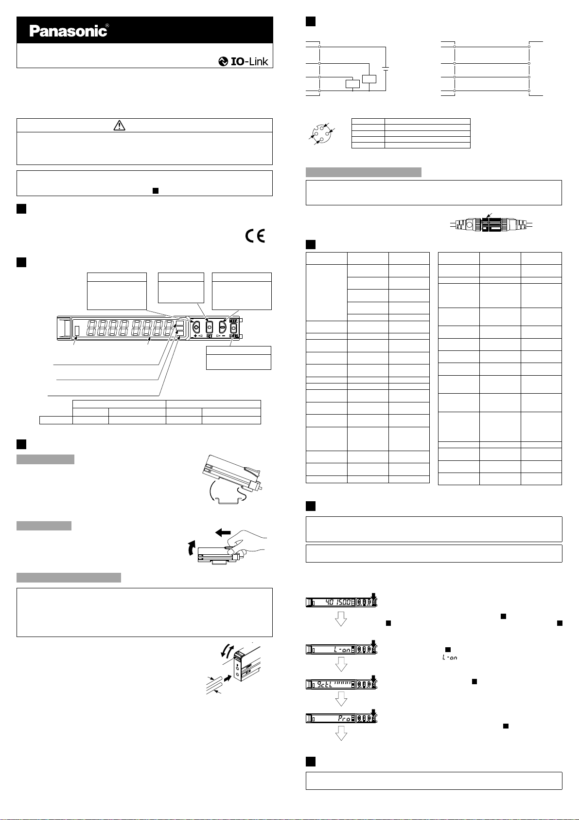
2 PART DESCRIPTION
UP key
Teaching
•
Threshold value fi ne
•
adjustment
Select setting items
•
Sensing output operation
indicator (Orange)
Lights when setting SENSING OUTPUT OPERATION MODE
・
Lights when setting LIGHT SENSITIVITY SETTING MODE
・
IO-Link communication
Note
Function Lamp OFF Lights up Flashes Lights up
Digital display (Green / Red)
MODE indicator: L / D (Yellow)
MODE indicator: CUST (Yellow)
indicator / MODE indicator
:PRO (Yellow) (Note)
During IO-Link non communication During IO-Link communication
Normal status Main unit PRO mode Normal status Main unit PRO mode
3 MOUNTING
How to mount
1.
Fit the rear part of the mounting section of
the amplifi er on a DIN rail.
2.
Press down the rear part of the mounting
section of the unit on the DIN rail and fi t the
front part of the mounting section to the DIN
rail.
How to remove
1.
Push the amplifi er forward.
2.
Lift up the front part of the amplifi er to remove
it.
12
PRO MODE
SET key
Teaching
•
Confi rm setting
•
contents
2.
2.
Press down
Lift up
.”
DOWN key
Teaching
•
Threshold value fi ne
•
adjustment
Select setting items
•
MODE key
Select modes
•
Cancel during setting
•
35mm width DIN rail
1.
Push forward
1.
Fit
4 WIRING
●
When used as general-purpose sensor
(Brown / 1) +V
(White / 2) DO
(Black / 4) C/Q Note
Load
(Blue / 3) 0V
Load
+
24V DC
±10%
-
<Terminal arrangement of M12 connector type>
Terminal No. Terminal name
1
4
2
3
Note: When the product is used as a general-purpose sensor, the IO-Link communication (C/Q) is generated in the
same way as control output (DO).
1+V
2 Control output (DO)
30V
4 IO-Link communication (C/Q) Note
How to mount M12 connector
If the fixed ring loosens, the connector will come off, causing this product to
generate a communication error.
Before use, be sure to check that the fi xed ring is not loose.
Firmly tighten the fi xed ring by rotating it.
●
● When connected to IO-Link master
(Brown / 1) +V +V
(White / 2) DO DI
(Black / 4) C/Q C/Q
(Blue / 3) 0V 0V
This product IO-Link master
• Recommendedextension cable
Extension cable with connectors
on both ends
XS5W series
[OMRON Corporation]
Fixed ring
5 LIST OF FUNCTIONS
Function
Teaching
Threshold value
Setting
Key lock function Set / Release Index12
Output Operation
Setting
Light sensitivity
setting
Response time
setting
Timer setting Timer mode Index64_1
Timer time setting Timer time Index64_2
Shift amount
setting
Shift threshold
valuet setting
Teaching lock
setting
Setting items in
digital display
setting
Time period hold
setting
Setting of digital
display turning
ECO Setting
Note: For the IO-Link communication setting, refer to the attached sheet, “
Setting on main unit
2-point teaching
(SET Key)
Limit-teaching
(UP Kye)
Limit-teaching
(DOWN Kye)
Full-auto teaching
(SET Kye)
Teaching cancel
Threshold value
fine Adjustment
Light-ON/DarkON
Light sensitivity
select
Selection from
4-mode
Amount select Index74_1
Shift threshold
valuet
Lock ON / OFF Index85
Incident light
intensity / Displayed
in percentage /
Peak/bottom value
Hold
ON / OFF Index83_2
Turning ON / OFF Index82
FULL / ON / OFF Index80
IO-Link communication setting
(Note)
Index2
Index2
Index2
Index2
Index2
Index60
Index61_1
Index77
Index66
Index74_2
Index83_1
Function
Display
adjustment setting
Reset setting Execution Index2
Emitting
frequency setting
Emitting frequency
(Interference
revention setting)
Threshold value tracking
Cycle setting
Threshold value tracking
Output Operation Setting
Threshold value tracking
Storage cycle setting
Threshold value tracking
Algorithm setting
Preventive
maintenance threshold
value 1 setting
Preventive
maintenance threshold
value 2 setting
Preventive
maintenance
threshold value
detection lag time
setting
Operating time
Number of data
save operations
Notification Flag
Setting
Notification Event
Code
Setting on main unit
Set / Release Index2
Disabled / Interference
revention/Ambient
environment
sesistance
Selection from
4-mode
Cycle(time) Index75_1
ON / OFF Index75_2
Storage cycle
(each time)
Teaching mode
select
- Index160
- Index161
- Index162
- Index163
- Index164
- Index168
- Index169
Index List.”
(IMJE-FXLINDEX)
IO-Link communication setting
(Note)
Index76_1
Index76_2
Index75_3
Index75_4
6 OPERATION PROCEDURE
The changed settings are not stored if turning the power OFF while setting.
Therefore, confi rm the settings by pressing the SET key before turning the power
OFF.
If settings are confi gured simultaneously on the main unit side and on the IO-Link
communication side, the settings that are applied last will be enabled.
How to connect the fi ber cable
● Mount the fi ber cables in the state power is not supplied.
● Be sure to fi t the attachment to the fi ber cables fi rst before inserting that to the
amplifier. For details, refer to the instruction manual enclosed with the fiber
cables.
● Insert the fi ber cables slowly into the inlets until they stops. Excessive force may
damage the product.
3.
1.
Snap the fiber lock lever down till it stops
completely.
2.
Insert the fi ber cables slowly into the inlets
until they stops. (Note)
3.
Return the fiber lock lever to the original
Fiber for emitter
1.
Snap
Fiber lock lever
position till it stops.
Note: With the coaxial refl ective type fi ber, insert the single core fi ber cable into the beam-emitting inlet “P” and the
multi-core fi ber cable into the beam-receiving inlet.
If they are inserted in reverse, the sensing performance will deteriorate.
Return
2.
Insert
Fiber for receiver
● When turning ON the power, RUN mode is displayed and the digital display shows
the threshold value (green) and the incident light intensity (red).
<RUN mode>
<Sensing output operation mode>
<Light sensitivity setting mode>
<PRO mode>
<RUN mode>
• Displays threshold value (green) and incident light intensity (red).
• Teaching, threshold value fi ne adjustment and key lock function can
be set.
• For setting method of each function, refer to “
8
THRESHOLD VALUE FINE ADJUSTMENT FUNCTION
“
KEY LOCK FUNCTION
• Select either Light-ON or Dark-ON.
• For the setting, refer to “
• The default setting is “ ” (Light-ON).
• Displays light sensitivity setting and enables its setting.
• For detailed information, refer to “
MODE
.”
• Detailed settings can be set for maximizing the performance of
individual functions.
• For setting items and setting method, refer to “
.”
10
SENSING OUTPUT OPERATION MODE
11
7
TEACHING MODE
,” or “
LIGHT SENSITIVITY SETTING
12
PRO MODE.”
7 TEACHING MODE
Be sure that detection may become unstable depending on the use environment in
teaching if less margin is applied.
● Teaching can be set in RUN mode (And during IO-link communication).
,”
9
.”
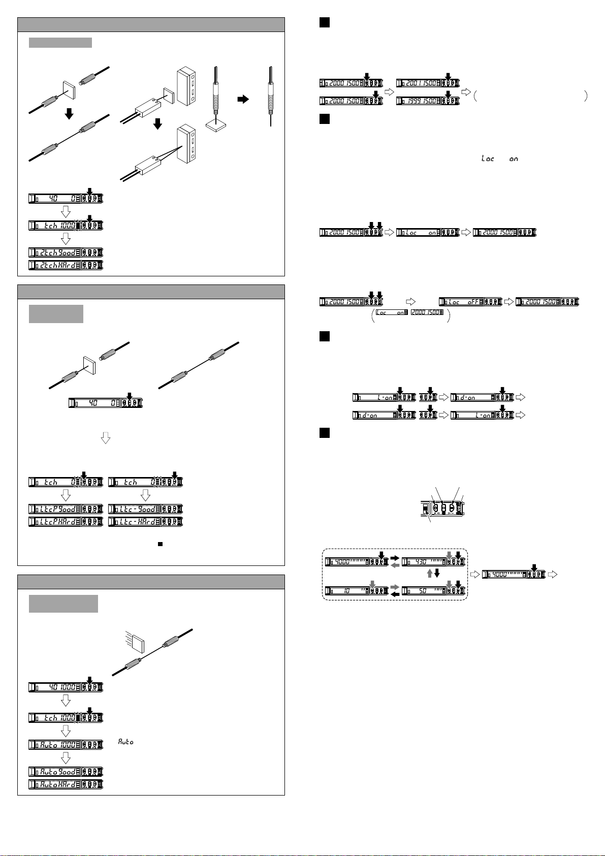
2-point teaching
1
Useful when sensing object can be set
This is basic teaching method.
<Mirror refl ection type>
1
<Refl ective type><Thru-beam type>
12
8 THRESHOLD VALUE FINE ADJUSTMENT FUNCTION
● Set the fine adjustment of threshold value in RUN mode (And during IO-link
communication).
Press down
UP / DOWN key
Press down
SET key
Confi rmed
Automatically set without pressing down SET
key in approx. 2 sec.
2
2
1.
Press the SET key in the sensing object present condition
(System command / Index2: 0x43)
2.
Press the SET key in the sensing object absent condition
(System command / Index2: 0x44)
Stable sensing is possible
Stable sensing is not possible
.
.
Useful when sensing object cannot be set
Limit-teaching
<Common to thru-beam type, mirror refl ection type and refl ective type>
Note 1: The shift value of approx. 15% is an initial value. Display of the shift value can be changed to
percentage [approx. 0 to 999% (unit 1 %)] or incident light intensity [0 to 9999 (unit 1)].
For setting the shift amount, refer to <PRO1> in “
Note 2: At the time of limit teaching. UP key(System command / Index2: 0x4B)
DOWN key (System command / Index2: 0x4C)
This is teaching method in case small object or object in
back ground are existing.
or
1.
Press the SET key in the sensing object present
condition or non sensing object present condition.
2.
Thru-beam type, mirror reflection
type: Threshold level is shifted to
high value (low sensitivity) when
UP key is pressed down, and it is
shifted to low value (high sensitivity)
when DOWN key is pressed down.
(Note 1) (Note 2)
Reflective type: Threshold level is
shifted to high value (low sensitivity)
when DOWN key is pressed down,
and it is shifted to low value (high
sensitivity) when UP key is pressed
down. (Note 1) (Note 2)
Stable sensing is possible
Stable sensing is not possible
12
PRO MODE
.”
Useful when not want to stop production line and to keep the sensing object move
9 KEY LOCK FUNCTION
● The key lock function prevents key operations so that the conditions set in each
setting mode are not inadvertently changed (It is also possible to set at IO-link
communication).
● If operating key switch after key lock is set, “ ” is indicated on the
digital display.
<Set key lock>
Press down SET
+ MODE keys
simultaneously for
3 sec or longer
<Release key lock>
Press down SET
+ MODE keys
simultaneously for
3 sec or longer
are displayed
10
SENSING OUTPUT OPERATION MODE
,
● When MODE indicator: L / D (yellow) lights up, sensing output operation can be
set (And during IO-link communication).
Press down
UP / DOWN key
11
LIGHT SENSITIVITY SETTING MODE
● When the MODE indicator: CUST (yellow) lights up, light sensitivity setting can be
displayed (And during IO-link communication).
● By pressing down UP key or DOWN key, light sensitivity setting can be changed.
● Press SET key to confi rm the setting.
SET key DOWN key
UP key
Press down UP / DOWN key
Automatic
MODE indicator
CUST (Yellow)
MODE key
Automatic
Press down
SET key
Confi rmed
Confi rmed
Press down
SET key
Confi rmed
Full-auto teaching
This is method to conduct teaching doing sensing
object is moving.
<Common to thru-beam type, mirror refl ection type and refl ective type>
1.
Pressing
down long
Automatic
Pressing SET key down
2.
Run the sensing object on the line and hold down the SET
(System command / Index2: 0x47)
key
3.
“
” is displayed on the digital display (green) and
when the sensing object passed through, release the SET
(System command / Index2: 0x48)
key
Stable sensing is possible
Stable sensing is not possible
..
..
 Loading...