

Page 1
Operating and Installation Instructions
19
1/8
"
486 mm
11
13/16
"
300 mm
Mode d'emploi et notice d'installation
ENGLISHFRANÇAISESPAÑOL
Instrucciones de uso e instalación
Range Hood
Hotte de cuisine
Campana de cocina
Model No.
Modèle
Nº de modelo
FV-36RCQL1
FV-30RCQL1
READ AND SAVE THESE INSTRUCTIONS
Thank you for purchasing this Panasonic product.
Please read these instructions carefully before attempting to install, operate or service
the Panasonic product. Please carefully read the “GENERAL SAFETY INFORMATION”
Failure to comply with instructions could result in personal injury or property damage.
Please explain to users how to operate and maintain the product after installation, and
this booklet should be presented to users.
Please retain this booklet for future reference.
LIRE ET CONSERVER CE DOCUMENT
Nous vous remercions d'avoir acheté ce produit Panasonic. Veuillez lire attentivement
ces instructions avant d’essayer d’installer, d’utiliser ou de réparer ce produit Panasonic.
Veuillez également lire attentivement la section “CONSIGNES DE SÉCURITÉ” .
Le non-respect des instructions peut entraîner un risque de blessure corporelle et
de dommages matériels. Veuillez expliquer aux utilisateurs comment utiliser et eectuer
l’entretien de ce produit après l’installation et leur présenter ce document.
Conservez ce document pour référence ultérieure.
LEA Y CONSERVE ESTAS INSTRUCCIONES
Gracias por comprar este producto Panasonic. Lea atentamente estas instrucciones antes
de instalar, utilizar o mantener este producto Panasonic. Lea atentamente el capítulo
“INFORMACIÓN GENERAL SOBRE SEG URIDAD”. El incumplimiento de las instrucciones
podría causar daños personales o materiales. Explique a los usuarios cómo utilizar y
mantener el producto después de la instalación. Se recomienda ofrecer este manual a los
usuarios. Conserve este manual para consultas futuras.
Page 2

CONTENTS
GENERAL SAFETY INFORMATION .................................................................................................................................................................. 3
SUPPLIED ACCESSORIES ................................................................................................................................................................................... 7
OPERATION ............................................................................................................................................................................................................ 8
MAINTENANCE ..................................................................................................................................................................................................... 9
DIMENSIONS ....................................................................................................................................................................................................... 10
WIRING DIAGRAM ............................................................................................................................................................................................11
SPECIFICATIONS ................................................................................................................................................................................................. 11
INSTALLATION .....................................................................................................................................................................................................12
PRODUCT SERVICE ........................................................................................................................................................................................... 18
2
Page 3
GENERAL SAFETY INFORMATION
For Your Safety
To reduce the risk of injury, loss of life, electric shock, re, malfunction, and damage to
equipment or property, always observe the following safety precautions.
Explanation of symbol word panels
The following symbol word panels are used to classify and describe the level of hazard,
injury, and property damage caused when the denotation is disregarded and improper use
is performed.
Denotes a potential hazard that could
result in serious injury or death.
WARNING
Denotes a hazard that could result in
minor injury.
CAUTION
ENGLISH
The following symbols are used to classify and describe the type of instructions to be
observed.
This symbol is used to alert users to a specic operating procedure that
must be followed in order to operate the unit safely.
This symbol is used to alert users to a specic operating procedure that
must not be performed.
3
Page 4
WARNING
TO REDUCE THE RISK OF A RANGE TOP GREASE FIRE:
a) Never leave surface units unattended at high settings. Boilovers cause smoking and greasy spillovers that may
ignite. Heat oils slowly on low or medium settings.
b) Always turn hood ON when cooking at high heat.
c) Clean ventilating fans frequently. Grease should not be allowed to accumulate on fan or lter.
d) Use proper pan size. Always use cookware appropriate for the size of the surface element.
TO REDUCE THE RISK OF INJURY TO PERSONS IN THE EVENT OF A RANGE
TOP GREASE FIRE, OBSERVE THE FOLLOWING:
a) SMOTHER FLAMES with a close-tting lid, cookie sheet, or metal tray, then turn o the burner. BE CAREFUL TO
PREVENT BURNS. If the ames do not go out immediately, EVACUATE AND CALL THE FIRE DEPARTMENT.
b) NEVER PICK UP A FLAMING PAN – You may be burned.
c) DO NOT USE WATER, including wet dishcloths or towels – a violent steam explosion will result.
d) Use an extinguisher ONLY if:
1) You know you have a Class ABC extinguisher, and you already know how to operate it.
2) The re is small and contained in the area where it started.
3) The re department is being called.
4) You can ght the re with your back to an exit.
Based on “ Kitchen Firesafety Tips ” published by NFPA.
TO REDUCE THE RISK OF FIRE, ELECTRIC SHOCK, OR INJURY TO PERSONS,
OBSERVE THE FOLLOWING:
a) Use this unit only in the manner intended by the manufacturer. If you have questions, contact the manufacturer.
b) Before servicing or cleaning unit, switch power o at service panel and lock the service disconnecting means to
prevent power from being switched on accidentally. When the service disconnecting means cannot be locked,
securely fasten a prominent warning device, such as a tag, to the service panel.
GROUNDING INSTRUCTIONS
a) This appliance must be grounded. In the event of an electrical short circuit, grounding reduces the risk of electric
shock by providing an escape wire for the electric current. This appliance is equipped with a cord having a grounding
wire with a grounding plug. The plug must be plugged into an outlet that is properly installed and grounded.
b) Improper grounding can result in a risk of electric shock.
c) Consult a qualied electrician if the grounding instructions are not completely understood, or if doubt exists as
to whether the appliance is properly grounded.
d) Do not use an extension cord. If the power supply cord is too short, have a qualied electrician install an outlet
near the appliance.
4
Page 5
WARNING
TO REDUCE THE RISK OF FIRE, ELECTRIC SHOCK, OR INJURY TO PERSONS,
OBSERVE THE FOLLOWING:
a) Installation work and electrical wiring must be done by qualied person(s) in accordance with all applicable
codes and standards, including re-rated construction.
b) Sucient air is needed for proper combustion and exhausting of gases through the ue (chimney) of fuel
burning equipment to prevent back drafting. Follow the heating equipment manufacturer’s guideline and safety
standards such as those published by the National Fire Protection Association (NFPA), and the American Society
for Heating, Refrigeration and Air Conditioning Engineers (ASHRAE), and the local code authorities.
c) When cutting or drilling into wall or ceiling, do not damage electrical wiring and other hidden utilities.
d) Ducted fans must always be vented to the outdoors.
- Clean the lters and all laden surfaces on a regular basis.
- To provide protection against electric shock, connect to properly grounded outlets only.
- To reduce the risk of re, use only metal ductwork.
-
Stop using the unit when any abnormality / failure occurs and turn “OFF” the power switch or pull out the 3 pin plug.
Example of abnormality failure:
- Abnormal noise or heat.
- Abnormal emission of smell / smoke.
- Fire or oil ignition.
- Insert the Power Plug rmly, otherwise it may cause re or electric shock.
- The supply cord must be set properly not to be damaged. The manufacturer declines all liability if the safety
standards are not observed.
- The socket used to connect the installed equipment to the electrical power supply must be within reach:
otherwise, install a mains switch to disconnect the Range Hood when required.
- The wall plugs must have a secure grip.
- The enclosed screws and wall plugs are suitable for solid brickwork or solid concrete. Suitable fasteners must be
used for other structures (e.g. plasterboard, porous concrete, porous bricks).
- The maximum length of the ue fastening screws (supplied by the manufacturer) must be 0
Use of non-compliant screws with these instructions can lead to danger of an electrical nature.
- Keep in mind that installations with dierent types of fastening systems from those supplied, or which are not
compliant, can cause electrical and mechanical seal danger.
- Clean the Power Plug regularly with dry cloth, otherwise it may cause insucient insulation due to moisture, and
may cause re.
- There is a re risk if cleaning is not carried out in accordance with the instructions.
- Accessible parts may become hot when used with cooking appliances.
- Always supervise the cooking process during the use of deep-fryers:
Overheated oil can catch re.
- A statement to the eect that when the product is to no longer be used, it must not be left in place but remove,
to prevent it from possibly failing.
- Always check that all the electrical parts (lights, exhaust device), are o when the appliance is not being used.
- This appliance is not intended for use by young children or inrm persons unless they have been adequately
supervised by a responsible person to ensure that they can use the appliance safely. Young children should be
supervised to ensure they do not play with the appliance.
- To reduce the risk of re or electric shock, do not use this fan with any solid-state speed control device.
- Do not connect the appliance to ues (from boilers, replaces, etc.).
- Do not discard the packaging or any part of it, or leave it unattended.
It can constitute a suocation hazard for children, especially the plastic bags.
- Do not ambé under the Range Hood.
- Never cook on “open” ames under the Range Hood.
- Do not leave open, unattended ames under the Range Hood.
-
Do not switch “OFF” or “ON” the Range Hood when there may be a gas leak in your gas hob. Gas explosion may result in.
- Do not handle the Power Plug with wet hand, otherwise it may cause electric shock.
- Do not disassemble the unit for reconstruction.
33
/64"
(13mm).
ENGLISH
5
Page 6
CAUTION
- Use the neutral detergent only.
- For residential use only.
- The minimum distance between supporting surface for the cooking vessels on the hob and lowest part of the Range Hood
must be at least 25 9⁄16" (650 mm).
- To reduce risk of re and to properly exhaust air, be sure to duct air outside.
- Before the appliance is put into operation, all the protective lm must be removed.
- Check whether the Range Hood is installed securely and horizontally.
- Always operate the Range Hood when using gas cooker.
- Avoid parts from falling when detaching it for cleaning.
- Ensure that the wires inside the Range Hood are not disconnected or cut:
in the event of damage, contact your nearest Servicing Department.
- When disconnect the Power Plug, hold the plug itself. Do not pull the cord anyway.
The cord may be damaged, it may cause re or electric shock.
- Be sure to disconnect the Power Plug from the wall outlet or switch o the breaker when not using for a long time.
- Product must be installed on the wall, which is strong enough to hold the unit. Reinforce it if necessary.
- The Range Hood should be installed so that the metal part of the product and mounting screw do not contact with any metalic item
inside the wall, such as metal laths, wire laths and metal plate, it is possible to cause re harzards in case of electrical leak.
- During installation, always use personal protective equipment (e.g.: Safety shoes, gloves) and adopt prudent and proper conduct.
- Please wear gloves during the cleaning work.
- Make sure that the electric service supply voltage is AC 120 V, 60 Hz.
- Protect the supply wiring from sharp edges, oil, grease, hot surfaces, chemicals or other objects.
- Suitable for use in a household cooking zone.
- Before installing the Range Hood, check the integrity and function of each part.
Should anomalies be noted, do not proceed with installation and contact the Dealer.
- Do not vent exhaust air into spaces within walls or ceilings or into attics, crawl spaces, or garages.
- For general ventilating use only. Do not use to exhaust hazardous or explosive materials and vapors.
- It is dangerous to modify or attempt to modify the characteristics of this system.
In the event of malfunctions or if repairs are required to the appliance, do not attempt to solve the problems directly. Repairs
performed by unqualied persons may cause damage. For all repair and other work on the appliance, contact the service centre.
- Insist on original spare parts.
- Do not insert pointed metal objects (cultery or utensils) into any aperture in the Range Hood.
- Do not use a steam cleaner for cleaning the appliance. The steam could reach the electronics, damaging them and causing
short-circuits.
- Do not use too much moisture or water around the push button control panel and lighting devices in order to prevent humidity
from reaching electronic parts.
- Do not clean electrical parts, or parts related to the motor inside the Range Hood, with liquids or solvents.
- Never use petrol, benzene, thinner or any other similar chemicals to clean the product.
- Do not use abrasive products.
- Do not carry out any cleaning operations when parts of the Range Hood are still hot.
- Never use the product in a wet place. It may cause re or failure.
- During operation, never insert ngers or other objects into any aperture in the Range Hood. Failure or injury may result in.
- Do not put anything on the Range Hood. It may cause re, failure or injury.
- Do not kink the supply wiring.
- Never use the Range Hood without the metal lters:
in this case, grease and dirt will deposit in the equipment and compromise its operation.
6
Page 7
SUPPLIED ACCESSORIES
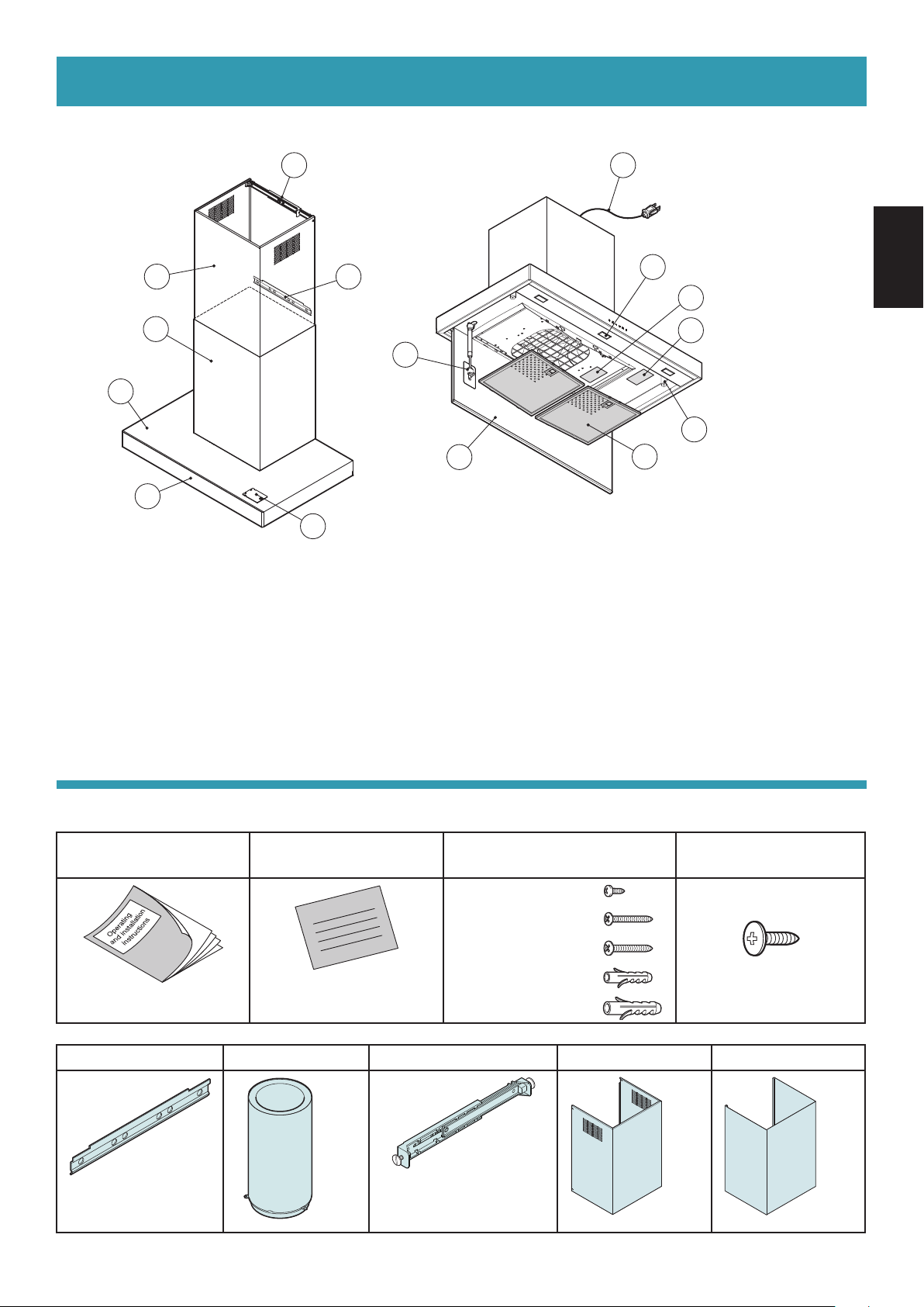
Part identication :
1 13
122
3
4
5
14
1 - Bracket
2 - Extension
3 - Chimney
4 - Range Hood body
5 - Electronic push button control panel
6 - LED spotlight illumination x 2 (FV-30RCQL1)
x 3 (FV-36RCQL1)
6
(FV-30RCQL1)
11
(FV-36RCQL1)
11
8
9
7
10
7 - Perimeter suction panel
8 - Piston bar
9 - Magnet x 2
10 - Metal lter x 2
11 - Name plate
12 - Support bar
13 - Power cord
14 - Module support for add-on Module that provides additional
features (Module sold separately)
ENGLISH
Supplied accessories :
A - Operating and
installation instructions
1 pc
B - Warranty sheet C - Screw pack 1 D - Screw pack 2
Ø3.9 x 9.5 mm (10 pcs)
Warranty sheet
2 pcs
Ø4.5 x 40 mm (4 pcs)
Ø5 x 50 mm (2 pcs)
Ø6 wall plug (4 pcs)
Ø8 wall plug (2 pcs)
Ø4.2 x 12.5 mm (3 pcs)
E - Support bar F - Pipe G - Bracket H - Extension I - Chimney
1 pc
1 pc
Wall plugs are for solid brickwork or solid concrete.
1 pc
2 screws
Ø4 x 7 mm
1 pc
1 pc
7
Page 8

OPERATION
1
2
3
1
212
1
2
3
Key No.
1 2 3 4 5 6
Key 1 : [ Function ] Filter alarm / Timer
The BLUE lighting indicates that the metal lter alarm is active (after 30 hours); to deactivate this alarm and
reset the hour meter, press the button for 3 seconds.
The BLUE blinking indicates that the timer function is active. This function can be activated only if the motor
is already active with any speed when the key is pressed. This function activates the auto power o function
of the Range Hood after 15 minutes. The Range Hood can be turned o by the user and the function will be
disabled.
Key 2 : [ Function ] On (1st Speed) / O motor / 24 hours function
Press the key to select the 1st speed (the BLUE lighting).
When the 1st speed is on and the key is pressed, both the LED and MOTOR will turn o.
If the motor is active with any speed, to turn o the Range Hood, press key 2 twice.
When the LED is o, if the key is pressed for at least 3 sec, the 24 hours function activates.
During the 24 hours function (which lasts 24 hours), the LED blinks.
From the activation of this function, the Range Hood will remain active for 1 hour at 1st speed, then it will stop
for 3 hours and reactivate for another hour. These cycles are repeated until timeout. With activation of this
function, other speeds may not be selected. To deactivate this function, keep key 2 pressed for at least 3 seconds.
Key 3 : 2nd Speed
If the LED is o and another speed is active, press the key to select the 2nd speed (the BLUE lighting) and turn
the LED associated to the previously selected speed o.
If the LED is o and no speed is active, the key is disabled.
When the LED is on, key 3 is disabled.
To turn o the Range Hood, press key 2 twice.
Key 4 : 3rd Speed
If the LED is o and another speed is active, press the key to select the 3rd speed (the BLUE lighting) and turn
the LED associated to the previously selected speed o.
If the LED is o and no speed is active, the key is disabled.
When the LED is on, key 4 is disabled.
To turn o the Range Hood, press the key 2 twice.
Key 5 : 4th Speed (BLUE blinking)
If the LED is o and another speed is active, press the key to select the 4th speed (the BLUE blinking) and turn
the LED associated to the previously selected speed o.
If the LED is o and no speed is active, the key is disabled.
When the LED is on, key 5 is disabled.
The fourth speed lasts 7 minutes, then the Range Hood changes to the third speed.
To turn o the Range Hood, press key 2 twice.
Key 6 : Light
Light : Pressing key 6 will turn the light on and o. The BLUE lighting if the light is on.
8
Page 9
MAINTENANCE
WARNING
Before servicing or cleaning unit, switch power o at service panel and lock the service
disconnecting means to prevent power from being switched on accidentally.
When the service disconnecting means cannot be locked, securely fasten a prominent
warning device, such as a tag, to the service panel.
CAUTION
Regular maintenance guarantees proper operation and performance over time.
Special attention is to be paid to the metal lters : frequent cleaning of the metal lters and their supports ensures that no
ammable grease is accumulated.
CLEANING OF EXTERNAL SURFACES
You are advised to clean the external surfaces of the Range Hood at least once every 15 days to prevent oily substances and
grease from sticking to them.
Alternatively and for all the other types of surfaces, it can be cleaned using a damp cloth, slightly moistened with mild,
liquid detergent or denatured alcohol.
Complete cleaning by rinsing well and drying with soft cloths.
Do not use products that contain abrasive substances or cloths NOT specically designed for cleaning steel.
The glass panels can only be cleaned with specic, non-corrosive or non-abrasive detergents using a soft cloth.
The Manufacturer declines all responsibility for failure to comply with these instructions.
CAUTION
CLEANING OF INTERNAL SURFACES
Do not clean electrical parts, or parts related to the motor inside the Range Hood, with liquids or solvents.
METAL FILTERS
It is advised to frequently wash the metal lters (at least once a month) leaving them to soak in boiling water and cleaning
solution for 1 hour, taking care not to bend them.
- Do not use corrosive, acid or alkaline detergents.
- Rinse them well and wait for them to be completely dry before reassembling them.
- Washing in a dishwasher is permitted, however, it may cause the metal lter material to darken : to reduce the possibility of
this problem from happening, use low-temperature washes (131 °F/ 55 °C max.).
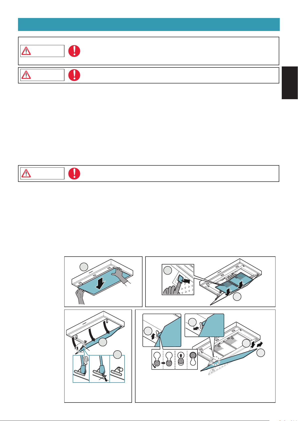
To remove the perimeter suction panel and the metal lters as shown gure below.
Please wear gloves during the cleaning work.
Be careful when removing the perimeter suction panel in case oil has accumulated on it and
may fall out.
ENGLISH
How to remove of the
metal lters
How to remove of
the perimeter suction
panel
1
1
Piston bar
pin
Please slowly remove the pin
while supporting it with
ngers so that it will not fall.
2
2
3
4
3
5
6
Be sure to check that the pin is attached to the piston bar to
reassemble the perimeter suction panel. If not attached, the
perimeter suction panel cannot be supported at the specied
position.
9
Page 10
DIMENSIONS
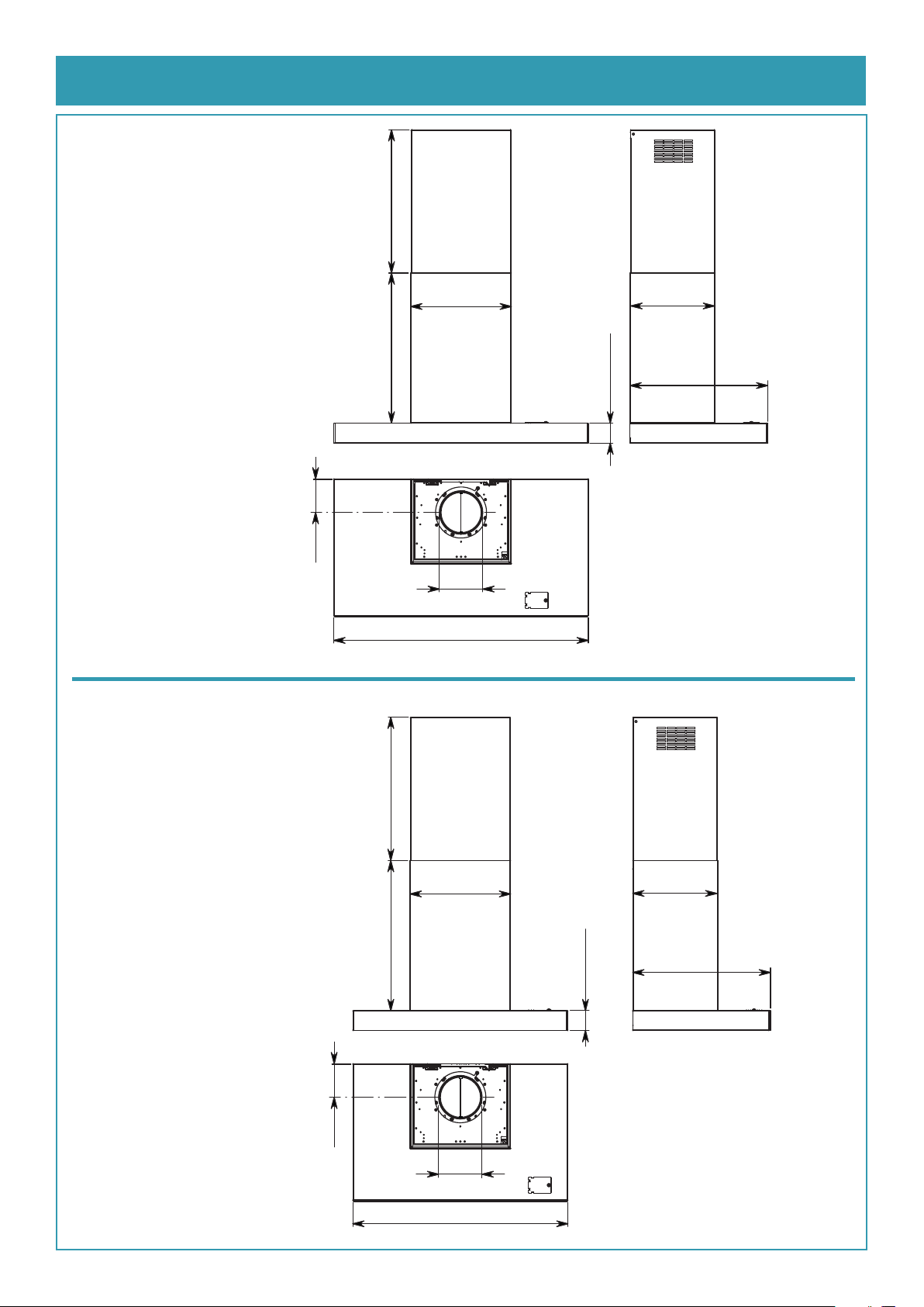
FV-36RCQL1
max. 19 7/8"
max. 505 mm
FV-30RCQL1
4 5/8"
118 mm
529 mm
20 13/16"
14”
355 mm
Ø5 7/8"
Ø150mm
35 3/8"
900 mm
11 13/16"
300 mm
2 3/4" - 70 mm
19 1/8"
486 mm
4 5/8"
118 mm
max. 19 7/8"
max. 505 mm
529 mm
20 13/16"
Ø150 mm
14”
355 mm
Ø5 7/8"
29 7/8"
759 mm
11 13/16"
300 mm
19 1/8"
486 mm
2 3/4" - 70 mm
10
Page 11
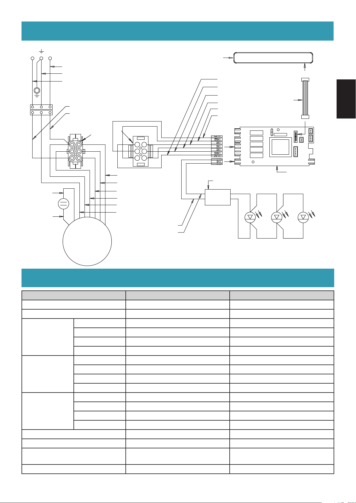
WIRING DIAGRAM
NL
WHITE
GREEN
BLACK
BROWN
BLUE
CONTROL PANEL
WHITE (2° SPEED)
ORANGE (4° SPEED)
GRAY (LINE)
RED (NEUTRAL)
BLACK (3° SPEED)
BLUE (1° SPEED)
5 V
FLAT CABLE
ENGLISH
PIN
REAR VIEW
1
2
3
WHITE (2° SPEED)
BLUE (1° SPEED)
GRAY (3° SPEED)
BLACK (4° SPEED)
RED
YELLOW - GREEN
4
5
6
MAIN BOARD
TRANSFORMER
12 V
BROWN
BLUE
LED LIGHT SPOT
BROWN
YELLOW
REAR VIEW
4
5
6
PIN
1
2
3
M
~
SPECIFICATIONS
Model No. FV-36RCQL1 FV-30RCQL1
Voltage AC 120V AC 120V
Frequency 60 Hz 60 Hz
4th Speed 328 331
Power (W)
Air Volume
at 0.1" WG
(CFM)
Noise (sones)
Lamp 1.2 W x 3 1.2 W x 2
Pipe Diameter Ø8" ( Ø203 mm ) Ø8" ( Ø203 mm )
Dimension (L x W x H)
Weight 75 lb. (34 kg) 71 lb. (32 kg)
3rd Speed 226 227
2nd Speed 180 182
1st Speed 137 147
4th Speed 440 440
3rd Speed 340 340
2nd Speed 240 240
1st Speed 130 130
4th Speed 4.0 4.5
3rd Speed 2.0 3.0
2nd Speed 0.9 1.0
1st Speed <0.3 <0.3
35 3/8" x 19 1/8" x 23 37/64"
( 900 mm x 486 mm x 600 mm )
29 7/8" x 19 1/8" x 23 37/64"
( 759 mm x 486 mm x 600 mm )
HVI Certied performance based on HVI Procedures 915, 916, and 920.
11
Page 12
INSTALLATION
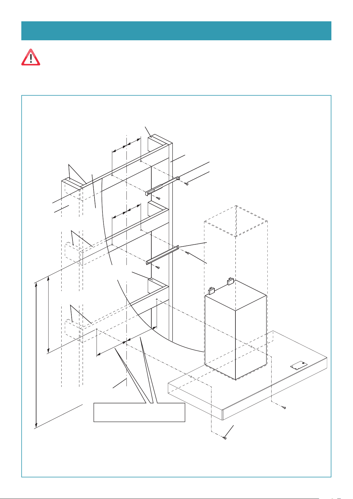
Before installing the Range Hood, carefully read chap. "GENERAL SAFETY INFORMATION".
Installation preparation
Additionally install reinforcement wooden frames between the studs behind the dry wall.
Measure the height B referring to Fig. A in next page.
Reinforcement wooden frame
3 15/16"
3 15/16"
Reinforcement wooden frame
Dry wall
154.5
mm
154.5
mm
Stud
Bracket
V6
2 - Ø4.5x40
B
Stud
Reinforcement
wooden frame
Reinforcement
wooden frame
548 mm
21 9/16"
4 1/64"
102
mm
Reinforcement
wooden frame
X
4 1/64"
102
mm
Support bar
V1
2 - Ø5x50
X
12
Top of
the cooking surface
Centerline
FV-30RCQL1 : 10 11/16" (272 mm)
X =
FV-36RCQL1 : 11 7/16" (290 mm)
V2
2 - Ø4.5x40
Page 13
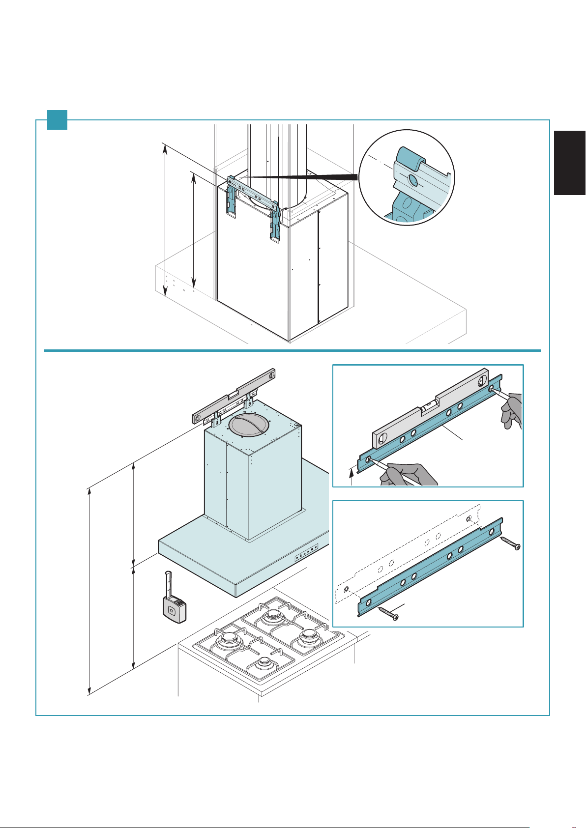
Phase 1 (Fig. A)
(1) Place the support bar (A) on the wall at a height B from the cooking surface resulting from the sum of the quotas :
C + 22 15/16" (582 mm).
(2) With a spirit level, verify the horizontal alignment;
(3) Mark 2 screw positions at the ends of support bar.
(4) Fasten the support bar (A) with the 2 relative screws (V1 Ø5x50).
A
582 mm
22 15/16”
460 mm
18 1/18”
ENGLISH
B
22 15/16”
( 582 mm )
C
Min. 25 9/16”
( Min. 650 mm )
(1)
(2)
(2)
(3)
A
(3)
(4)
V1
2 - Ø5x50
13
Page 14
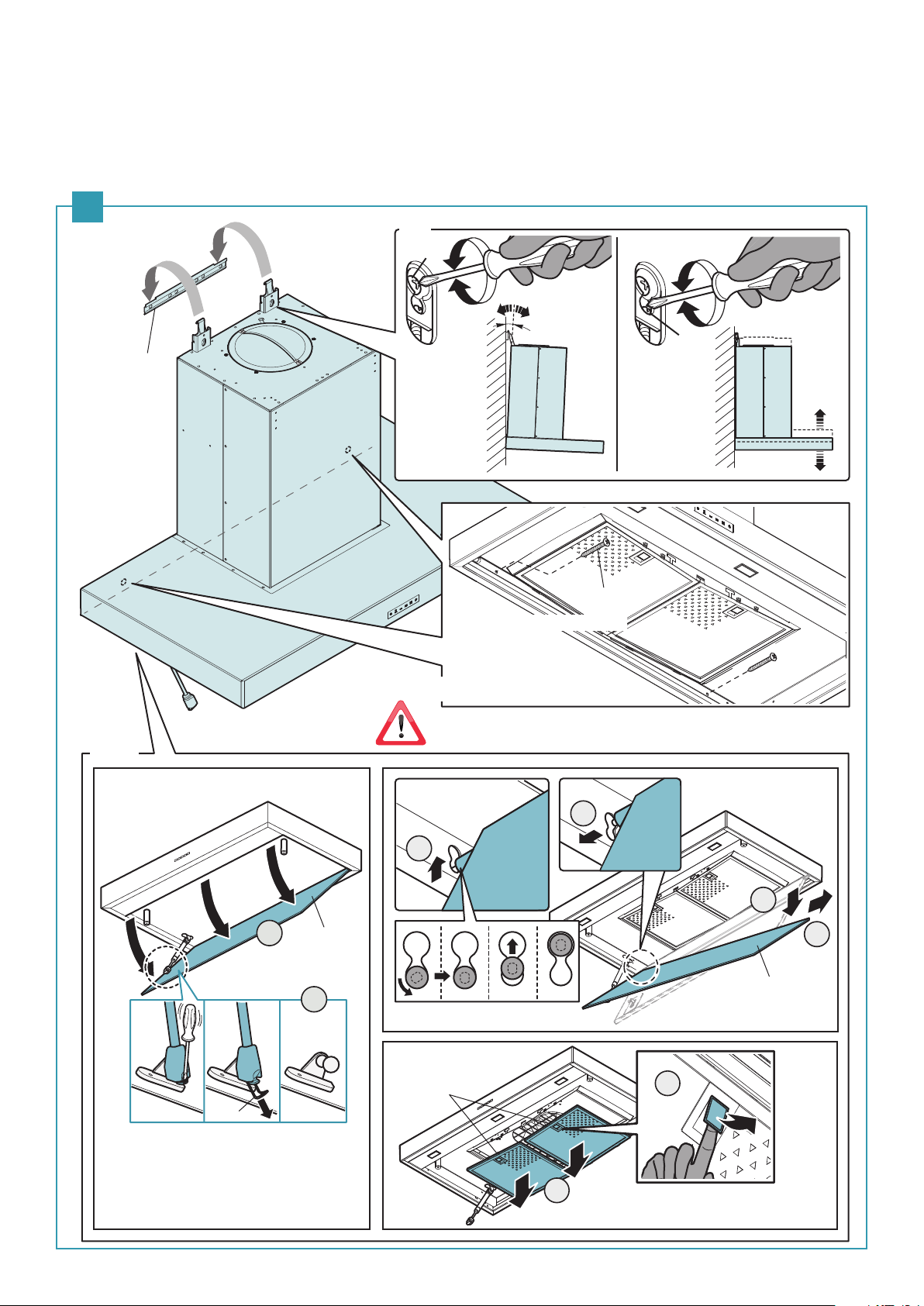
D
Phase 2 (Fig. B)
(1) Hook the Range Hood on the support bar (A).
(2) Adjust the alignment of the Range Hood, using the xing screws. The upper screw (D) adjusts the distance from the wall, the
lower one (E) the vertical scrolling.
(3) Remove the perimeter suction panel (F) and the metal lters (G).
(4) To prevent the Range Hood from falling due to a pressure below, fasten it to the wall with 2 relative screw (V2 Ø4.5x40) using
the appropriate holes on the back of the Range Hood.
B
(1)
A
(2)
E
(3)
V2
2 - Ø4.5 x 40
(4)
Mandatory safety screws
4
3
5
1
F
2
6
F
14
Pin
Please slowly remove the pin while
supporting it with ngers so that it
will not fall.
G
7
8
Metal lter protective lm must be removed.
Page 15
J
K
K
L
H
(1)
(2)
(3)
Ø8”
(Ø203 mm)
28” (711 mm)
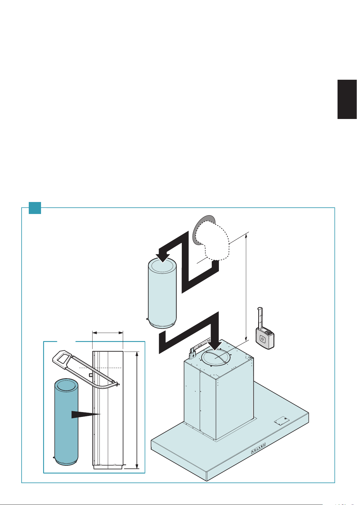
Phase 3 (Fig. C)
Connect the Range Hood to the external exhaust (H).
(1) Measure the height J.
(2) Cut the pipe (K) to the required length.
(3) Carefully insert the pipe (K) in the motor tting (L).
Note :
- The exhaust conveyor that protrudes from the upper part of the Range Hood must be connected with the pipe that conducts
the fumes and vapours in an external output.
- The fumes and vapours are discharged outside through the exhaust pipe.
To this end, the Range Hood outlet tting must be connected via a pipe, to an external output.
- The diameter of the fume discharge duct must be no smaller than the Range Hood connection.
- The outlet pipe must have a diameter not less than that of the Range Hood tting.
- The outlet pipe must have :
• A slight slope downwards (drop) in the horizontal sections to prevent condensation from owing back into the motor.
• The duct must be installed not to bend it in the immediate vicinity of the discharge hole. Otherwise, the return valve will get
stuck with the duct, and will not work for the exhaust properly.
• Reduce curves to the bare minimum, and check that the length of the ducts is also the bare minimum.
• You are required to insulate the pipes if it passes through cold environments.
ENGLISH
C
15
Page 16
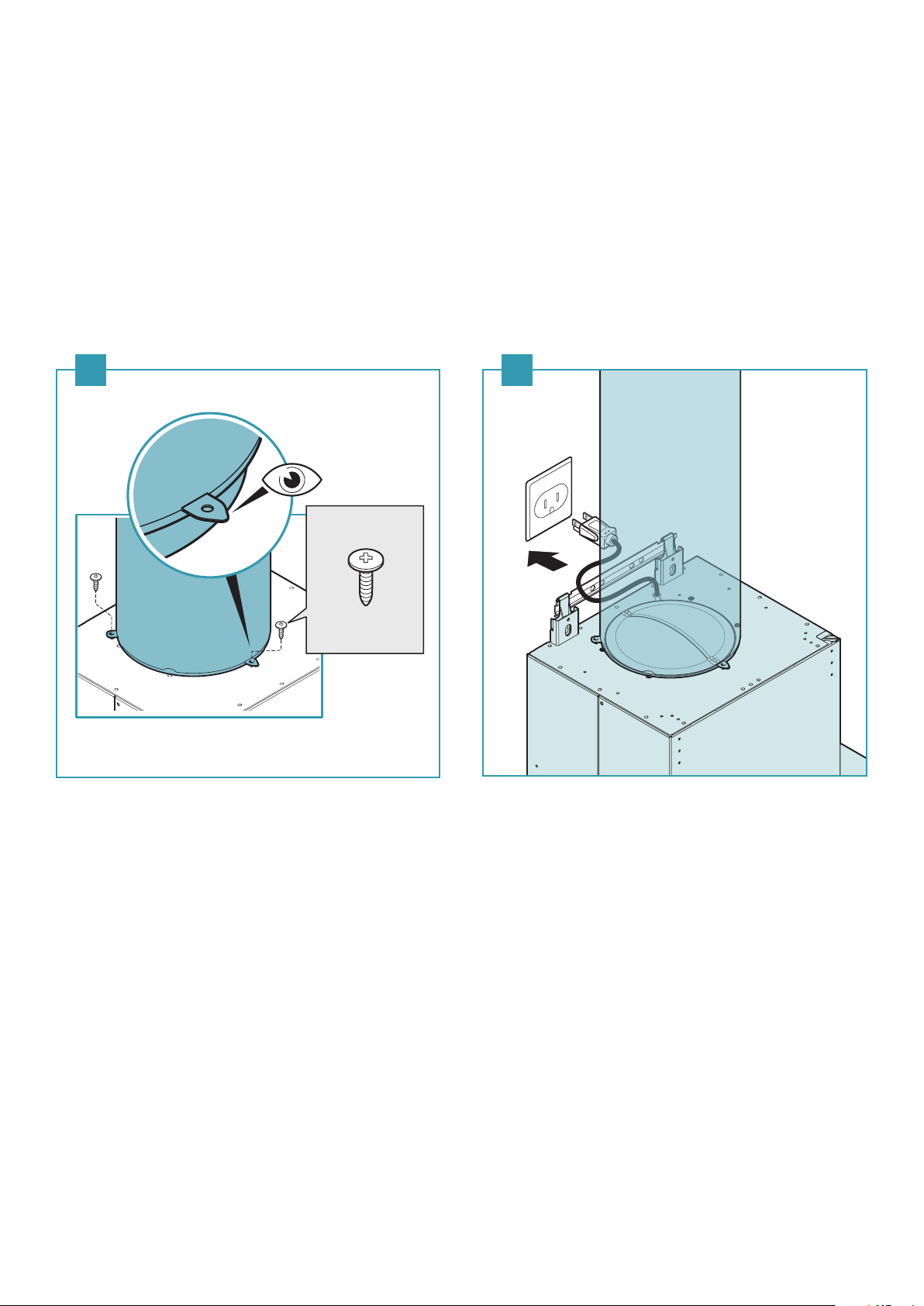
Phase 4 (Fig. D, E)
(1) Fasten the pipe (K) to the Range Hood body with the 3 screws (V3 Ø4.2x12.5).
(2) Set up the electric connection to power the Range Hood only after having disconnected the main power supply switch
and complied with current regulations.
Note :
- The electrical system to which the Range Hood is to be connected must be in accordance with local standards and supplied
with earthed connection in compliance with safety regulations in the country of use.
It must also comply with local standards regarding radio antistatic properties.
- Before connecting the Range Hood to the electrical mains power supply, check that : the power supply plug and cable do
not come into contact with temperatures exceeding 158 °F (70 °C);
- Check that the relief valve and the electrical system are able to support the load of the appliance (see the technical
specications displayed on the rated plate in the Range Hood).
D E
(2)
(1)
K
V3
3 - Ø4.2x12.5
16
Page 17

Phase 5 (Fig. F)
(1) Insert the extension (M) into the chimney (N).
(2) Fasten the chimney (N) to the Range Hood body using the screws (V4 Ø3.9x9.5).
(3) Slide the extension (M) until it reaches the desired height.
(4) Remove 2 screws (V5 Ø4x7) from the bracket (P).
Place the bracket (P) on the wall, verify the horizontal alignment with a spirit level and mark 2 screw positions at the ends.
(5) Fasten the bracket (P) with the 2 relative screws (V6 Ø4.5x40).
(6) Screw the extension (M) to the bracket (P) using the 2 screws (V5 Ø4x7).
- Power the Range Hood complying with the regulations in force.
F
V5
2 - Ø4x7
P
(4)
M
(1)
N
V4
(2)
8 - Ø3.9x9.5
ENGLISH
P
P
(5)
M
P
V6
2 - Ø4.5x40
(3)
(6)
V5
2 - Ø4x7
17
Page 18

PRODUCT SERVICE
Warning Concerning Removal of Covers. The unit should be serviced by qualied technicians only.
Your product is designed and manufactured to ensure a minimum of maintenance. Should your
unit require service or parts, call Panasonic Call Center at 1-866-292-7299 (USA) or
1-800-669-5165 (Canada).
WARNING!
The Manufacturer reserves the right to make changes to the equipment at any time and without
prior notice. Printing, translation and reproduction, even partial, of this manual are bound by the
Manufacturer's authorisation. Technical information, graphic rapresentations and specifications
in this manual are for information purposes and cannot be divulged.
Attach your purchase receipt here.
For your records :
The model number and serial number of this product can be found on the name plate in the
Range Hood. Please note them in the space provided and keep for future reference.
Model No. :
Serial No. :
Date of purchase :
Dealer's name :
Dealer's adress :
Telephone number :
Panasonic Corporation of North America
Two Riverfront Plaza, Newark, NJ 07102
www.panasonic.com
© Panasonic Corporation 2018
18
Panasonic Canada Inc.
5770 Ambler Drive, Mississauga, Ontario L4W 2T3
www.panasonic.com
Printed in Italy
ZY02-C68
Fa1212k0
Page 19

TABLE DES MATIÈRES
CONSIGNES DE SÉCURITÉ ............................................................................................................................................................................... 20
ACCESSOIRES FOURNIS ...................................................................................................................................................................................24
FONCTIONNEMENT .......................................................................................................................................................................................... 25
MAINTENANCE ................................................................................................................................................................................................... 26
DIMENSIONS ....................................................................................................................................................................................................... 27
SCHÉMA DE CONNEXIONS ............................................................................................................................................................................28
SPÉCIFICATIONS ................................................................................................................................................................................................. 28
INSTALLATION .....................................................................................................................................................................................................29
SERVICE TECHNIQUE ....................................................................................................................................................................................... 35
FRANÇAIS
19
Page 20

CONSIGNES DE SÉCURITÉ
Pour votre sécurité
An de réduire les risques de blessure, de décès, de chocs électriques, d'incendie, de
dysfonctionnement et de dommages aux équipements ou aux biens, veuillez toujours
observer les consignes de sécurité suivantes.
Explication des panneaux de signalisation
Les panneaux de signalisation ci-dessous servent à classier et indiquer les niveaux de
risque, de blessure et de dommage aux biens résultant du non-respect de l'avertissement
et d'une utilisation inappropriée.
Indique un risque potentiel pouvant
MISE EN GARDE
ATTENTION
Les symboles suivants servent à classier et indiquer les types d'instruction à observer.
Ce symbole sert à alerter les utilisateurs de la présence d'une procédure
précise à suivre an d'utiliser l'appareil en toute sécurité.
Ce symbole sert à alerter les utilisateurs de la présence d'une procédure
d'utilisation précise à ne pas exécuter.
entraîner des blessures graves, voire
mortelles.
Indique un risque potentiel pouvant
entraîner des blessures légères.
20
Page 21

MISE EN GARDE
AFIN DE RÉDUIRE LE RISQUE D'INCENDIE DE GRAISSE SUR LA CUISINIÈRE :
a) Ne laissez jamais des unités de surface réglées sur des températures élevées sans surveillance. Les débordements
provoquent de la fumée et des résidus graisseux qui peuvent s'enammer. Faites chauer les huiles doucement,
à des températures faibles ou moyennes.
b) Mettez toujours la hotte en marche lorsque vous cuisinez à température élevée.
c) Nettoyez fréquemment les ventilateurs d'aération. La graisse ne doit pas s'accumuler sur le ventilateur ou le ltre.
d) Utilisez une poêle de taille appropriée. Utilisez toujours des ustensiles de cuisine appropriés à la taille de
l'élément de surface.
AFIN DE RÉDUIRE LE RISQUE DE BLESSURE PHYSIQUE EN CAS D'INCENDIE DE GRAISSE SUR LA CUISINIÈRE,
RESPECTEZ LES CONSIGNES SUIVANTES :
a) ÉTOUFFEZ LES FLAMMES à l'aide d'un couvercle étanche, d'une plaque à biscuits ou d'un plateau de métal, puis
mettez le brûleur hors marche. SOYEZ ATTENTIF AFIN D'ÉVITER TOUTE BRÛLURE. Si les ammes ne s'éteignent
pas immédiatement, ÉVACUEZ ET APPELEZ LES POMPIERS.
b) NE SAISISSEZ JAMAIS UNE POÊLE ENFLAMMÉE – Vous pourriez vous brûler.
c) N'UTILISEZ PAS D'EAU, ni de serviettes ou torchons mouillés – cela entraînerait une violente explosion de vapeur.
d) Utilisez un extincteur UNIQUEMENT si :
1) Vous savez que vous disposez d'un extincteur de classe ABC et que vous savez déjà comment l'utiliser.
2) L'incendie est peu important et conné à la zone où il s'est déclaré.
3) Les pompiers ont été appelés.
4) Vous pouvez combattre l'incendie en ayant le dos à proximité d'une sortie.
Sur la base des conseils de sécurité en cas d'incendie dans une cuisine “ Kitchen Firesafety Tips ” publiés par la
NFPA.
FRANÇAIS
AFIN DE RÉDUIRE LE RISQUE D'INCENDIE, DE CHOCS ÉLECTRIQUES OU DE BLESSURES,
RESPECTEZ LES CONSIGNES SUIVANTES :
a) N'utilisez l'appareil qu'aux ns prévues et recommandées par son fabricant. Au besoin, communiquez avec ce
dernier.
b) Avant de nettoyer ou de faire la maintenance de l'appareil, coupez l'alimentation sur le panneau de service et
verrouillez le dispositif d'alimentation an de prévenir tout rétablissement accidentel. Si le verrouillage n'est pas
possible, posez un avis très visible sur le panneau de service.
CONSIGNES DE MISE À LA TERRE
a) Cet appareil doit être mis à la terre. En cas de court-circuit, le l de mise à la terre limite le risque de choc électrique
parce qu'il assure le retour du courant à la terre. L'appareil est livré avec un cordon muni d'un l de terre et d'une
che de mise à la terre, qui doit être branchée sur une prise mise à la terre correctement installée.
b) Une mise à la terre incorrecte peut entraîner des risques de choc électrique.
c) Consultez un électricien compétent en cas de doute sur ces consignes de mise à la terre ou en cas d'incertitude
concernant la mise à la terre correcte du circuit sur lequel l'appareil est branché.
d) N'utilisez pas de cordon de rallonge. Si le cordon d'alimentation est trop court, faites installer une prise par un
électricien compétent à proximité de l'appareil.
21
Page 22

MISE EN GARDE
AFIN DE RÉDUIRE LE RISQUE D'INCENDIE, DE CHOCS ÉLECTRIQUES OU DE BLESSURES,
RESPECTEZ LES CONSIGNES SUIVANTES :
a) Conez l'installation et les connexions électriques à une personne qualiée. L'installation doit être conforme aux
codes et normes applicables, y compris les normes en matière de parement pare-feu.
b) An de prévenir tout risque de contre-tirage, un ot d'air susant est requis pour assurer la combustion et
l'évacuation des gaz à travers la cheminée de tout appareil de combustion. Suivez les instructions du manufacturier
de l'équipement de chauage et observez les normes de sécurité en vigueur en matière de prévention des incendies
de même que celles des codes locaux.
c) Lors d'une découpe dans un mur ou un plafond ou lors de leur perçage, prenez garde de ne pas endommager le
câblage électrique et toute autre installation cachée.
d) Tout ventilateur canalisé doit donner directement sur l'extérieur.
- Nettoyez les ltres et toutes les surfaces sales de manière régulière.
- An d'assurer la protection contre les chocs électriques, branchez dans une prise correctement mise à la terre.
- An de réduire le risque d'incendie, utilisez uniquement un conduit en métal.
- En cas d'anomalie/de défaillance, arrêtez d'utiliser l'appareil et placez l'interrupteur d'alimentation sur “OFF” ou
retirez la che à 3 branches.
Exemple d'anomalie :
- Bruit ou chaleur anormale.
- Émission d'une odeur / de fumée anormale.
- Incendie ou inammation d'huile.
- Insérez la che d'alimentation solidement, sinon cela peut entraîner un incendie ou un choc électrique.
- Le cordon d'alimentation doit être correctement disposé pour ne pas être endommagé. Le fabricant décline toute
responsabilité en cas de non-respect des normes de sécurité.
- La prise utilisée pour le branchement électrique doit être facilement accessible avec l'appareil installé : si cela
n'était pas possible, prévoyez un interrupteur général pour déconnecter la hotte en cas de besoin.
- Les chevilles murales doivent avoir une bonne prise.
- Les vis et chevilles murales jointes sont adaptées aux briques ou au béton solide. Utilisez des éléments de xation
appropriés en cas d'autres structures (telles que des plaques de plâtre, du béton poreux ou des briques poreuses).
- La longueur maximum de la vis de xation de la cheminée (fournie par le fabricant) est de 13 mm (33/64 po).
L'utilisation de vis non conformes avec les présentes instructions peut comporter des risques de nature électrique.
- Tenez compte du fait que l'installation avec des systèmes de xation diérents de ceux fournis ou non conformes
peut comporter des risques de nature électrique et de tenue mécanique.
- Nettoyez régulièrement la prise électrique à l'aide d'un chion sec, car cela pourrait sinon entraîner une isolation
insusante due à l'humidité, et provoquer un incendie.
- Un risque d'incendie existe si le nettoyage n'est pas eectué conformément aux instructions.
- Les pièces accessibles peuvent devenir chaudes lorsqu'elles sont utilisées avec des appareils de cuisson.
- Contrôlez les friteuses pendant l'utilisation : l'huile surchauée pourrait s'enammer.
- Lorsque le produit n'est plus utilisé, il ne doit pas être laissé en place mais retiré an d'empêcher sa chute
probable.
- Vériez toujours que tous les composants électriques (éclairage, dispositifs d'aspiration) sont hors marche lorsque
vous n'utilisez pas l'appareil.
- Cet appareil n'est pas destiné à être utilisé par de jeunes enfants ou des personnes inrmes, à moins qu'ils ne
soient adéquatement supervisés par une personne responsable qui s'assure qu'ils utilisent l'appareil en toute
sécurité. Surveillez les jeunes enfants et faites en sorte qu'ils ne jouent pas avec l'appareil.
- An de réduire le risque d'incendie ou de chocs électriques, n'utilisez pas ce ventilateur avec un système de
commande électronique de la vitesse.
- Ne reliez pas l'appareil aux conduits d'évacuation des fumées dues à la combustion (chaudières, cheminées, etc.).
- Ne vous débarrassez pas de l'emballage ou d'une de ses parties, et ne le laissez pas sans surveillance. Il peut
représenter un danger de suocation pour les enfants, en particulier les sacs en plastique.
- Ne faites pas de ambées sous la hotte.
- Ne faites pas cuire avec une amme “nue” en dessous de la hotte.
- Ne laissez pas de ammes nues sous la hotte.
- Ne placez pas l'interrupteur de la hotte de cuisine sur “OFF” ou “ON” lorsqu'un risque de fuite de gaz se présente
dans votre plaque de cuisson au gaz. Cela peut provoquer une explosion de gaz.
- Ne manipulez pas la che d'alimentation avec les mains mouillées, sinon cela peut entraîner un choc électrique.
- Ne démontez pas l'appareil pour le reconstruire.
22
Page 23

ATTENTION
- Utilisez un détergent neutre uniquement.
- Pour emploi domestique seulement.
- La distance minimale entre la surface d'appui du récipient de cuisson sur la plaque et la partie la plus basse de la hotte doit être d'au
moins 650 mm (25 9⁄16 po).
- Pour réduire le risque d'incendie et pour évacuer correctement l'air, veuillez à évacuer l'air vers l'extérieur.
- Avant de mettre l'appareil en marche, toute pellicule de protection doit être retirée.
- Vériez que la hotte est installée solidement et horizontalement.
- Faites toujours fonctionner la hotte lors de l'utilisation d'une cuisinière au gaz.
- Empêchez les pièces de tomber lorsque vous les détachez pour nettoyer.
- Veiller à ce que les ls électriques à l'intérieur de la hotte ne soient pas débranchés ou coupés : dans le cas contraire, contacter le
centre de service le plus proche.
- Lorsque vous débranchez la che d'alimentation, tenez-la fermement. Ne tirez en aucun cas sur le cordon. Le cordon risque d'être
endommagé, ce qui peut provoquer un incendie ou un choc électrique.
- Assurez-vous de débrancher la che d'alimentation de la prise murale ou de désactiver le disjoncteur lorsque l'appareil n'est pas
utilisé pendant une longue période.
- Le produit doit être installé sur un mur assez solide pour supporter l'appareil. Renforcez-le si nécessaire.
- La hotte doit être installée de façon que les pièces métalliques du produit et les vis de montage ne soient pas en contact avec
un élément métallique à l'intérieur du mur, tel qu'un support métallique d'enduit, un chemin de câble et une plaque métallique, car
cela peut entraîner un risque d'incendie en cas de fuite électrique.
- Pendant l'installation, utilisez toujours des équipements de protection individuelle (ex. : des chaussures de sécurité, des gants) et
adoptez un comportement prudent et correct.
- Il est également recommandé de porter des gants lors du nettoyage.
- Assurez-vous que la tension nominale de l'alimentation secteur est 120 V c.a., 60 Hz.
- Protégez le cordon d'alimentation contre les arêtes vives, les lubriants, la graisse, les surfaces chaudes, les substances chimiques ou
tout objet susceptible de l'endommager.
- Convient à l'emploi dans une zone de cuisson domestique.
- Avant d'installer la hotte, vériez l'intégrité et la fonctionnalité de chaque partie : en cas de présence d'anomalies, ne procédez pas
à l'installation et contactez le revendeur.
FRANÇAIS
- N'évacuez pas l'air vicié dans des espaces situés entre des murs ou des plafonds ou dans des greniers, des vides sanitaires ou des
garages.
- Pour ventilation générale seulement. N'utilisez pas pour l'évacuation de vapeurs ou de matériaux dangereux ou explosifs.
- Il est dangereux de modier ou de tenter de modier les caractéristiques de ce système. En cas de dysfonctionnement ou si des
réparations de l'appareil sont nécessaires, n'essayez pas de résoudre les problèmes par vous-même. Les réparations eectuées par
des personnes non qualiées peuvent causer des dommages. Pour tous travaux de réparation et autres sur l'appareil, contactez le
centre de service.
- Exigez des pièces de rechange d'origine.
- N'insérez pas d'objets métalliques pointus (couverts ou ustensiles) dans une ouverture de la hotte de cuisine.
- N'utilisez pas de nettoyeur à vapeur pour le nettoyage de l'appareil. La vapeur peut atteindre les pièces électroniques et les
endommager, entraînant des courts-circuits.
- N'utilisez pas trop d'eau à proximité du panneau de commande à bouton-poussoir et des dispositifs d'éclairage pour éviter
que l'humidité atteigne des parties électroniques.
- Il est interdit de nettoyer les parties électriques ou celles relatives au moteur à l'intérieur de la hotte, avec des liquides ou des
solvants.
- N'utilisez jamais de pétrole, de benzène, de diluant ou autre produit chimique similaire pour le nettoyage du produit.
- N'utilisez pas de produits contenant des substances abrasives.
- N'eectuez pas d'opérations de nettoyage si des parties de la hotte sont encore chaudes.
- N'utilisez jamais le produit dans un endroit humide. Cela peut entraîner un incendie ou une défaillance.
- Lors du fonctionnement, n'insérez jamais les doigts ou d'autres objets dans une ouverture de la hotte. Cela peut provoquer une
défaillance ou des blessures.
- Ne posez rien sur la hotte de cuisine. Cela peut entraîner un incendie, une défaillance ou des blessures.
- Ne pliez pas le cordon d'alimentation.
- N'utilisez jamais la hotte sans les ltres métalliques; dans ce cas, la graisse et la saleté se déposeraient dans l'appareil et
compromettrait son fonctionnement.
23
Page 24

ACCESSOIRES FOURNIS
Identication des pièces :
1 13
122
3
4
5
14
1 - Support
2 - Prolongement
3 - Cheminée
4 - Boîtier de la hotte
5 - Panneau de commande à bouton-poussoir
6 - Lampe d'éclairage à DEL x 2 (FV-30RCQL1)
x 3 (FV-36RCQL1)
6
(FV-30RCQL1)
11
(FV-36RCQL1)
11
8
9
7
10
7 - Panneau périmétrique d'aspiration
8 - Barre de piston
9 - Aimant x 2
10 - Filtre métallique x 2
11 - Plaque signalétique
12 - Barre de support
13 - Cordon d'alimentation
14 - Support de module pour le module orant des caractéristiques
supplémentaires (vendu séparément)
Accessoires fournis :
A - Mode d'emploi et
B - Garantie C - Emballage de vis 1 D - Emballage de vis 2
notice d'installation
Ø3,9 x 9,5 mm (10 pièces)
1 pièce
Garantie
2 pièces
Ø4,5 x 40 mm (4 pièces)
Ø5 x 50 mm (2 pièces)
Ø6 Cheville (4 pièces)
Ø8 Cheville (2 pièces)
Ø4,2 x 12,5 mm (3 pièces)
E - Barre de support F - Tube G - Support H - Prolongement I - Cheminée
1 pièce
1 pièce
Les chevilles sont adaptées pour briques ou béton solide.
1 pièce
2 vis
Ø4 x 7 mm
1 pièce
1 pièce
24
Page 25

FONCTIONNEMENT
1
2
3
1
2
1
2
1
2
3
Numéro de touche
1 2 3 4 5 6
Touche 1 : [ Fonction ] Alarme de ltre / Minuterie
Le voyant BLEU xe indique que l'alarme de ltre à graisse est déclenchée (après 30 heures); pour désactiver
cette alarme et réinitialiser le compteur d'heures, appuyez sur la touche pendant 3 secondes.
Le voyant BLEU clignotant indique que la fonction de minuterie est activée. Cette fonction ne peut être
activée que si le moteur est déjà en marche, à n'importe quelle vitesse, lorsque vous appuyez sur la touche.
Cette fonction active la fonctionnalité d'arrêt automatique de la hotte au bout de 15 minutes. La hotte peut
être mise hors marche par l'utilisateur et la fonction sera désactivée.
Touche 2 : [ Fonction ] Mise en (1re vitesse) / Hors marche du moteur / Fonction 24 heures
Appuyez sur la touche pour sélectionner la première vitesse (voyant BLEU xe).
Lorsque la première vitesse est allumé, une pression sur la touche éteint aussi bien le voyant que le moteur.
Si le moteur est en marche, à n'importe quelle vitesse, pour mettre la hotte hors marche, appuyez deux fois sur
la touche 2.
Une pression sur la touche pendant au moins 3 secondes lorsque le voyant à DEL est éteint active la fonction
24 heures.
Durant la fonction 24 heures (qui dure au moins 24 heures), le voyant à DEL clignote.
À partir de l'activation de cette fonction, la hotte restera en marche pendant une heure à la 1re vitesse, puis se
mettra hors marche pendant trois heures et se réactivera pendant une heure. Ces cycles seront répétés jusqu'à
expiration du temps. Lorsque cette fonction est activée, il n'est pas possible de sélectionner d'autres vitesses.
Pour désactiver cette fonction, maintenez la touche 2 enfoncée pendant au moins 3 secondes.
FRANÇAIS
Touche 3 : 2e vitesse
Si le voyant est éteint et une autre vitesse est activée, appuyez sur la touche pour sélectionner la deuxième vitesse
(voyant BLEU xe) et éteindre le voyant associé à la vitesse précédente.
Si le voyant est éteint et si aucune vitesse n'est activée, la touche est désactivée.
Lorsque le voyant est allumé, la touche 3 est désactivée.
Pour mettre la hotte hors marche, appuyez deux fois sur la touche 2.
Touche 4 : 3e vitesse
Si le voyant est éteint et une autre vitesse est activée, appuyez sur la touche pour sélectionner la troisième vitesse
(voyant BLEU xe) et éteindre le voyant associé à la vitesse précédente.
Si le voyant est éteint et si aucune vitesse n'est activée, la touche est désactivée.
Lorsque le voyant est allumé, la touche 4 est désactivée.
Pour mettre la hotte hors marche, appuyez deux fois sur la touche 2.
Touche 5 : 4e vitesse (Voyant BLEU clignotant)
Si le voyant est éteint et une autre vitesse est activée, appuyez sur la touche pour sélectionner la quatrième
vitesse (voyant BLEU clignotant) et éteindre le voyant associé à la vitesse précédente.
Si le voyant est éteint et si aucune vitesse n'est activée, la touche est désactivée.
Lorsque le voyant est allumé, la touche 5 est désactivée.
La quatrième vitesse dure 7 minutes, puis la hotte de cuisine passe à la troisième vitesse.
Pour mettre la hotte hors marche, appuyez deux fois sur la touche 2.
Touche 6 : Éclairage
Éclairage : Appuyez sur la touche 6 pour allumer et éteindre la lampe. Le voyant BLEU xe si la lampe est allumée.
25
Page 26

MAINTENANCE
MISE EN GARDE
Avant de nettoyer ou de faire la maintenance de l'appareil, coupez l'alimentation sur le
panneau de service et verrouillez le dispositif d'alimentation an de prévenir tout
rétablissement accidentel. Si le verrouillage n'est pas possible, posez un avis très visible sur le
panneau de service.
ATTENTION
Un entretien constant garantit un bon fonctionnement et un bon rendement dans le temps.
Il faut accorder une attention particulière aux ltres métalliques : le nettoyage fréquent des ltres métalliques et de leurs
supports fait en sorte que les graisses inammables ne s'accumulent pas.
NETTOYAGE DES SURFACES EXTERNES
Il est conseillé de nettoyer les surfaces externes de la hotte au moins tous les 15 jours an d'éviter que les substances huileuses
ou grasses ne puissent les attaquer.
Sinon, pour tous les autres types de surface, le nettoyage doit être eectué en utilisant un chion humide légèrement
imprégné d'un détergent liquide neutre ou avec de l'alcool dénaturé.
Terminez le nettoyage en rinçant et en essuyant soigneusement avec des chions doux.
N'utilisez pas de produits contenant des substances abrasives, de chions rugueux ou de chions qui ne sont pas spécialement
conçus pour le nettoyage de l'acier.
Le nettoyage des panneaux en verre doit être eectué uniquement avec des détergents spéciques non corrosifs ni abrasifs
avec un chion doux.
Le fabricant décline toute responsabilité si ces instructions ne sont pas respectées.
ATTENTION
NETTOYAGE DES SURFACES INTERNES
Il est interdit d'utiliser des liquides ou des solvants pour nettoyer les parties électriques ou celles relatives au moteur à
l'intérieur de la hotte.
FILTRES MÉTALLIQUES
Il est conseillé de laver souvent les ltres métalliques (au moins tous les mois) en les laissant tremper pendant une heure
environ dans de l'eau bouillante avec un détergent à vaisselle, en évitant de les plier.
- N'utilisez pas de détergents corrosifs, acides ou alcalins.
- Rincez-les soigneusement et attendez qu'ils soient bien secs avant de les remonter.
-
Le lavage en lave-vaisselle est permis, mais il pourrait ternir le matériau des ltres métalliques : pour réduire cet inconvénient,
utiliser des lavages à basses températures (131 °F / 55 °C max.).
Retrait du panneau périmétrique d'aspiration et des ltres métalliques tel qu'illustré ci-dessous.
Comment retirer des ltres
métalliques
Il est également recommandé de porter des gants lors du nettoyage.
Soyez prudent lors du retrait du panneau périmétrique d'aspiration au cas où il y aurait de
l'huile qui pourrait tomber.
1
2
Comment retirer du
panneau périmétrique
d'aspiration
26
1
Barre de piston
2
Tige
Retirez délicatement la tige
en la tenant avec les doigts
pour ne pas l’échapper.
3
4
3
5
6
Assurez-vous que la tige est en place sur la barre de piston
lors du réassemblage du panneau périmétrique d’aspiration.
Si elle n’est pas xée, le soutien du panneau périmétrique
d’aspiration à l’endroit désigné ne sera pas possible.
Page 27

DIMENSIONS
FV-36RCQL1
max. 505 mm
max. 19 7/8 po
FV-30RCQL1
118 mm
4 5/8 po
po
529 mm
20 13/16
355 mm
14 po
Ø150mm
Ø5 7/8 po
900 mm
35 3/8 po
300 mm
11 13/16 po
486 mm
70 mm - 2 3/4 po
19 1/8 po
FRANÇAIS
po
118 mm
4 5/8
max. 505 mm
max. 19 7/8 po
529 mm
20 13/16 po
355 mm
14 po
Ø150mm
Ø5 7/8 po
759 mm
po
29 7/8
11 13/16
70 mm - 2 3/4 po
300 mm
po
486 mm
19 1/8 po
27
Page 28

SCHÉMA DE CONNEXIONS
NL
BLANC
VERT
NOIR
BRUN
BLEU
TIGE
PANNEAU DE COMMANDE
BLANC (2
ORANGE (4
GRIS (LIGNE)
ROUGE (NEUTRE)
NOIR (3
BLEU (1
e
VITESSE)
e
VITESSE)
e
VITESSE)
re
VITESSE)
5 V
CÂBLE PLAT
BRUN
JAUNE
VUE ARRIÈRE
4
5
6
M
TIGE
1
2
3
VUE ARRIÈRE
1
2
3
e
BLANC (2
BLEU (1
GRIS (3
NOIR (4
ROUGE
JAUNE - VERT
VITESSE)
re
VITESSE)
e
VITESSE)
e
VITESSE)
4
5
6
CARTE MÈRE
TRANSFORMATEUR
12 V
BRUN
BLEU
LAMPE À DEL
~
SPÉCIFICATIONS
Modèle FV-36RCQL1 FV-30RCQL1
Tension 120 V c.a. 120 V c.a.
Fréquence 60 Hz 60 Hz
Quatrième vitesse 328 331
Consommation
Électrique (W)
Débit d'air à 0,1 po
de colonne d'eau
(pi3/min)
Bruit (sone)
Lampe 1,2 W x 3 1,2 W x 2
Diamètre du conduit Ø203 mm ( Ø8 po ) Ø203 mm ( Ø8 po )
Dimensions (L x P x H)
Poids 34 kg ( 75 lb ) 32 kg ( 71 lb )
Spécications basées sur les normes HVI, conformément aux procédures 915, 916 et 920.
Troisième vitesse 226 227
Deuxième vitesse 180 182
Première vitesse 137 147
Quatrième vitesse 440 440
Troisième vitesse 340 340
Deuxième vitesse 240 240
Première vitesse 130 130
Quatrième vitesse 4,0 4,5
Troisième vitesse 2,0 3,0
Deuxième vitesse 0,9 1,0
Première vitesse <0,3 <0,3
900 mm x 486 mm x 600 mm
( 35 3/8 po x 19 1/8 po x 23 37/64 po )
759 mm x 486 mm x 600 mm
( 29 7/8 po x 19 1/8 po x 23 37/64 po )
28
Page 29

INSTALLATION
Avant d'eectuer l'installation de la hotte, lisez attentivement le chapitre. "CONSIGNES DE SÉCURITÉ".
Préparatifs d'installation
Installez également des ossatures de renfort en bois entre les montants derrière la cloison sèche.
Mesurez la hauteur B en vous référant à la Fig. A à la page suivante.
Ossature de renfort en bois
154,5
mm
po
mm
3 15/16
po
Montant
Support
V6
2 - Ø4,5x40
Ossature de renfort en bois
Cloison sèche
154,5
3 15/16
FRANÇAIS
Montant
548 mm
B
Ossature de
renfort en bois
Ossature de
renfort en bois
21 9/16 po
102
mm
4 1/64
po
Ossature de
renfort en bois
X
102
mm
4 1/64
po
Barre de
support
V1
2 - Ø5x50
X
Dessus de la surface
de cuisson
Ligne centrale
FV-30RCQL1 : 272 mm ( 10 11/16 po )
X =
FV-36RCQL1 : 290 mm ( 11 7/16 po )
V2
2 - Ø4,5x40
29
Page 30

Étape 1 (Fig. A)
(1)
Placez la barre de support (A) sur le mur à une hauteur B de la surface de cuisson résultant de la somme des valeurs :
C + 582 mm
(2) Avec un niveau à bulle, vériez l'alignement horizontal;
(3) Marquez les positions de 2 vis aux extrémités de la barre de support.
(4) Fixez la barre de support (A) avec les 2 vis (V1 Ø5x50).
(22 15/16 po).
A
582 mm
22 15/16 po
460 mm
18 1/18 po
B
582 mm
( 22 15/16 po )
C
Min. 650 mm
( Min. 25 9/16 po )
(1)
(2)
(2)
(3)
A
(3)
(4)
V1
2 - Ø5x50
30
Page 31

D
Étape 2 (Fig. B)
(1) Accrochez la hotte à la barre de support (A).
(2) Réglez l'alignement de la hotte à l'aide des vis de xation. La vis supérieure (D) permet de régler la distance de la paroi, celle
du bas (E) le décalement vertical.
(3) Retirez le panneau périmétrique d'aspiration (F) et les ltres métalliques (G).
(4)
Pour éviter que la hotte ne tombe suite à une pression du dessous, xez-la au mur avec les 2 vis (V2 Ø4,5x40) respectivement,
en utilisant les
trous prévus à l'arrière de la hotte.
B
(1)
A
(2)
E
FRANÇAIS
(3)
V2
2 - Ø4,5 x 40
(4)
Vis de sécurité obligatoires
4
3
5
1
F
2
6
F
Tige
Retirez délicatement la tige en la
tenant avec les doigts pour ne pas
l’échapper.
G
7
8
Pellicule de protection de ltre en
métal doit être retiré.
31
Page 32

Étape 3 (Fig. C)
Branchez la hotte à l'évacuation extérieure (H).
(1) Mesurez la hauteur J.
(2) Coupez le tube (K) selon la longueur requise.
(3) Insérez soigneusement le tube (K) dans le raccord du moteur (L).
Nota :
- La tuyauterie d'évacuation qui dépasse de la partie supérieure de la hotte doit être reliée au tuyau qui conduit les fumées et les
vapeurs vers la sortie externe.
- Dans cette version, les fumées et les vapeurs sont envoyées vers l'extérieur à travers un tuyau d'évacuation.
À cette n, le raccord de sortie de la hotte doit être raccordé par un tuyau à une sortie extérieure.
- Le diamètre du conduit d'évacuation des fumées ne doit pas être inférieur à la connexion de la hotte.
- Le tuyau de sortie des fumées doit avoir un diamètre supérieur à celui du raccord de la hotte.
- Le tuyau de sortie des fumées doit avoir :
・Une légère inclinaison vers le bas (chute) dans les troncons horizontaux pour éviter que, si de la condensation se forme,
celle-ci reue dans le moteur.
・Le conduit doit être installé de façon qu'il ne soit pas plié à proximité de l'orice d'évacuation. Dans le cas contraire, le
clapet anti-retour pourrait se bloquer et ne pas permettre aux gaz d'être aspirés correctement.
・Réduisez les courbes au strict minimum et vériez aussi que la longueur des conduits soit la plus courte possible.
・Il est nécessaire d'isoler la tuyauterie si elle passe par des endroits non chaués.
C
(2)
Ø203 mm
( Ø8 po )
K
(3)
H
J
(1)
L
32
K
711 mm ( 28 po )
Page 33

Étape 4 (Fig. D, E)
(1) Fixez le tube (K) au boîtier de la hotte avec les 3 vis (V3 Ø4,2x12,5).
(2)
Eectuez le branchement électrique pour l'alimentation de la hotte uniquement après avoir désactivé l'interrupteur général
et en respectant les réglementations en vigueur.
Nota :
- Le circuit électrique, auquel est reliée la hotte, doit être aux normes et muni d'un raccordement à la terre, conformément aux
normes de sécurité du pays d'utilisation; en outre, il doit être conforme aux normes locales sur l'antiparasite radio.
- Avant de raccorder la hotte au réseau électrique, vériez que la che et le cordon d'alimentation ne sont pas exposés à
des températures supérieures à 158 °F (70 °C);
- Vériez que la soupape de sûreté et le circuit électrique sont en mesure de supporter la charge de l'appareil (consultez les
spécications techniques achées sur la plaque signalétique de la hotte).
D E
(2)
(1)
FRANÇAIS
K
V3
3 - Ø4,2x12,5
33
Page 34

Étape 5 (Fig. F)
(1) Insérez le prolongement (M) dans la cheminée (N).
(2) Fixez la cheminée (N) au boîtier de la hotte au moyen des vis (V4 Ø3,9x9,5).
(3) Faites glisser le prolongement (M) jusqu'à ce qu'il atteigne la hauteur souhaitée.
(4) Retirez les 2 vis (V5 Ø4x7) du support (P).
Placez le support (P) sur le mur, vériez l'alignement horizontal avec un niveau à bulle et marquez les 2 points de forage aux
extrémités.
(5) Fixez le support (P) à l'aide de 2 vis (V6 Ø4,5x40).
(6) Vissez le prolongement (M) sur le support (P) à l'aide des 2 vis (V5 Ø4x7).
- Alimentez la hotte conformément à la réglementation en vigueur.
F
M
(1)
V5
2 - Ø4x7
P
P
(4)
P
N
V4
(2)
8 - Ø3,9x9,5
(5)
M
P
V6
2 - Ø4,5x40
(3)
(6)
34
V5
2 - Ø4x7
Page 35

SERVICE TECHNIQUE
Mise en garde à propos du retrait des couvercles. Conez toute réparation à un technicien qualié.
Votre appareil a été conçu et fabriqué pour n'exiger qu'un minimum de maintenance. Toutefois, dans le
cas où une révision ou des pièces deviendraient nécessaires, appelez le Centre d'appels Panasonic au
1-866-292-7299 (États-Unis) ou 1-800-669-5165 (Canada).
MISE EN GARDE
Le fabriquant se réserve le droit d'apporter des modications aux appareils à tout moment et sans préavis.
L'impression, la traduction et la reproduction, même partielle, du présent document doivent être autorisées
par le fabricant. Les informations techniques, les représentations graphiques et les spécications présentes
dans ce document sont indicatives et non divulguables.
Fixez le reçu d'achat ici.
FRANÇAIS
Pour vos dossiers :
Le numéro de modèle et le numéro de série de cet appareil sont situés sur la plaque signalétique
de la hotte de cuisine. Veuillez les inscrire dans l'espace prévu à cette n et les conserver pour
référence ultérieure.
Nº de modèle :
Nº de série :
Date d'achat :
Nom du détaillant :
Adresse :
Téléphone :
Panasonic Corporation of North America
Two Riverfront Plaza, Newark, NJ 07102
www.panasonic.com
© Panasonic Corporation 2018
Panasonic Canada Inc.
5770 Ambler Drive, Mississauga, Ontario L4W 2T3
www.panasonic.com
Imprimé en Italie
ZY02-C68
Fa1212k0
35
Page 36

ÍNDICE
INFORMACIÓN GENERAL SOBRE SEGURIDAD ........................................................................................................................................37
ACCESORIOS SUMINISTRADOS ....................................................................................................................................................................41
OPERACIÓN .........................................................................................................................................................................................................42
MANTENIMIENTO ..............................................................................................................................................................................................43
DIMENSIONES ..................................................................................................................................................................................................... 44
DIAGRAMA ELÉCTRICO ................................................................................................................................................................................... 45
ESPECIFICACIONES ...........................................................................................................................................................................................45
INSTALACIÓN ...................................................................................................................................................................................................... 46
SERVICIO TÉCNICO ........................................................................................................................................................................................... 52
36
Page 37

INFORMACIÓN GENERAL SOBRE SEGURIDAD
Por su seguridad
Para reducir el riesgo de lesión, muerte, choque eléctrico, incendio, avería y daños materia
o en el equipo, siempre cumpla con las siguientes medidas de seguridad.
Explicación de los letreros con símbolos
Los letreros con símbolos se utilizan para clasicar y describir el nivel de peligro, lesión y
daños materiales causados cuando se hace caso omiso de la indicación y se realiza un uso
incorrecto.
les
ESPAÑOL
Indica peligro de lesión grave o muerte.
ADVERTENCIA
Indica peligro de lesión menor.
PRECAUCIÓN
Los siguientes símbolos se utilizan para clasicar y describir el tipo de instrucciones
que deben cumplirse.
Este símbolo se emplea para alertar a los usuarios un procedimiento de
operación especíco obligatorio para utilizar el equipo de forma segura.
Este símbolo se emplea para alertar a los usuarios la prohibición de un
determinado procedimiento de operación.
37
Page 38

ADVERTENCIA
PARA REDUCIR EL RIESGO DE FUEGO GENERADO POR GRASA EN LA SUPERFICIE SUPERIOR DE UNA ESTUFA:
a) Nunca deje los quemadores superiores desatendidos cuando estén en posiciones altas de calor. Los derrames
generados por líquidos que hierven de más generan humo así como derrames grasosos que pueden incendiarse.
Caliente los aceites lentamente en posiciones bajas o medias de calor.
b) Siempre encienda la campana al cocinar con calor alto.
c) Limpie frecuentemente los ventiladores. No se debe dejar acumular grasa en el ventilador o el ltro.
d) Use el tamaño apropiado de sartén. Siempre use los trastes apropiados para el tamaño del quemador superior.
PARA REDUCIR EL RIESGO DE LESIONES A PERSONAS EN EL CASO DE LA GENERACIÓN DE FUEGO POR GRASA
EN LA SUPERFICIE SUPERIOR DE LA ESTUFA, ACATE LO SIGUIENTE:
a) AHOGUE LAS FLAMAS con una tapa que cierre ajustadamente, una charola para galletas o una charola metálica;
luego, apague el quemador. TENGA CUIDADO DE PREVENIR QUEMADURAS. Si las amas no se pagan
inmediatamente, EVACÚE Y LLAME AL DEPARTAMENTO DE BOMBEROS.
b) NUNCA TOME UNA SARTÉN QUE FLAMEA; puede quemarse.
c) NO USE AGUA, lo que incluye trapos de cocina húmedos o toallas húmedas; de lo contrario, se producirá una
explosión violenta de vapor.
d) Use un extinguidor SOLAMENTE si:
1) Usted sabe que tiene un extinguidor de clase ABC, y usted ya sabe cómo usarlo.
2) El fuego es pequeño y está contenido en el área en donde se inició.
3) Ya se ha llamado al departamento de bomberos.
4) Usted puede luchar contra el fuego teniendo una salida a sus espaldas.
Basado en “Consejos de seguridad contra el fuego en la cocina” (Kitchen Firesafety Tips), publicado por la NFPA.
PARA REDUCIR EL RIESGO DE INCENDIO, CHOQUE ELÉCTRICO O LESIONES,
CUMPLA CON LO SIGUIENTE:
a) Utilice este equipo sólo en la forma prevista por el fabricante. Si tiene preguntas, comuníquese con el fabricante.
b) Antes de mantener o limpiar el equipo, desconecte la energía del panel de servicio y bloquee los medios de
desconexión de servicio para evitar que la energía se active de manera accidental.Cuando no sea posible
bloquear los medios de desconexión del servicio, coloque rmemente sobre el panel de servicio un dispositivo
de advertencia bien visible, como una etiqueta.
INSTRUCCIONES PARA LA CONEXIÓN A TIERRA
a) Este aparato debe conectarse a tierra. En caso de ocurrir un cortocircuito, la conexión a tierra reduce el riesgo
de producirse un choque eléctrico por medio de un cable de escape para la corriente eléctrica. Este aparato está
equipado con un cable que tiene un alambre de conexión a tierra con una clavija de conexión a tierra. La clavija
debe estar conectada a un tomacorriente que esté debidamente instalado y puesto a tierra.
b) Una mala conexión a tierra puede producir un riesgo de choque eléctrico.
c) Consulte con un electricista calicado si no comprende totalmente las instrucciones para la conexión a tierra, o si
existe alguna duda con respecto a la correcta conexión a tierra del aparato.
d) No use un cable de extensión. Si el cable de alimentación es demasiado corto, llame a un electricista calicado
para que instale un tomacorriente cerca del aparato.
38
Page 39

ADVERTENCIA
PARA REDUCIR EL RIESGO DE INCENDIO, CHOQUE ELÉCTRICO O LESIONES,
CUMPLA CON LO SIGUIENTE
a) El trabajo de instalación y conexión eléctrica debe ser realizado por un electricista calicado conforme a las
normas y los códigos aplicables, incluidas las regulaciones relacionadas con la construcción ignífuga.
b) Se necesita suciente aire para que se lleve a cabo una combustión y una extracción adecuadas de los gases a
través del tubo de humos (chimenea) del equipo quemador de combustible, con el n de evitar el contratiro.
Siga las pautas y las normas de seguridad del fabricante del equipo de calentamiento, como las publicadas por
Asociación Nacional de Protección contra Incendios (NFPA, por sus siglas en inglés) y la Sociedad Estadounidense
de Ingenieros de Calefacción, Refrigeración y Aire Acondicionado (ASHRAE, por sus siglas en inglés) y las autoridades
normativas locales.
c) Cuando corte o perfore en una pared o un techo, no dañe los cables eléctricos ni otros servicios ocultos.
d) Los extractores con ductos siempre deben tener descarga hacia el exterior.
- Limpie periódicamente los ltros y todas las supercies cargadas de grasa.
-
Como protección contra el choque eléctrico, conecte el aparato solo a tomacorrientes debidamente conectados a tierra.
- Para reducir el riesgo de fuego, use ducto metálico solamente.
- Deje de usar el equipo cuando se produzca alguna anomalía o falla y coloque el interruptor de encendido en “OFF”
o desconecte la clavija de 3 polos.
Ejemplo de falla de anomalía:
- Ruido o calor anormales.
- Emisión anormal de olor o humo.
- Fuego o incendio de aceite.
- Inserte la clavija de alimentación rmemente; de lo contrario, podría producir fuego o choque eléctrico.
- El cable de alimentación debe quedar tendido correctamente para evitar que se dañe. El fabricante deslinda toda
responsabilidad en caso de falta de cumplimiento de las normas de seguridad.
- El tomacorriente utilizado para conectar el equipo instalado a la alimentación eléctrica debe ser de fácil alcance;
de lo contrario, instale un interruptor de alimentación para desconectar la campana puricadora cuando sea necesario.
- Los taquetes deben tener un agarre seguro.
- Los tornillos y los taquetes suministrados son adecuados para ladrillos sólidos o concreto sólido. Deben utilizarse
sujetadores adecuados para otras construcciones (por ejemplos, cartón-yeso, concreto poroso, ladrillos porosos).
- La longitud máxima de los tornillos de sujeción de la chimenea (suministrados por el fabricante) debe ser
pulg. (13 mm). El uso de tornillos que no cumplen con estas instrucciones puede generar un peligro de naturaleza
eléctrica.
- Tenga presente que las instalaciones con otros tipos de sistemas de sujeción distintos de los suministrados, o que
no cumplen con las instrucciones, pueden ocasionar un riesgo eléctrico y de sello mecánico.
- Limpie la clavija de alimentación periódicamente con un paño seco; de lo contrario, la humedad puede ocasionar
un aislamiento insuciente, lo cual puede producir fuego.
- Existe riesgo de fuego si la limpieza no se lleva a cabo de acuerdo con las instrucciones.
- Las piezas accesibles pueden calentarse si cuando se utilizan con artefactos de cocción.
- Siempre supervise el proceso de cocción durante el uso de freidoras: el aceite sobrecalentado puede incendiarse.
- Se indica que cuando el producto ya no se utilice, no debe quedar instalado, sino que debe quitarse para evitar su
posible caída.
- Siempre compruebe que todas las piezas eléctricas (luces, dispositivo de extracción) estén apagadas cuando el
aparato no está en uso.
- Este aparato no se destina para utilizarse por niños ni personas enfermas o de edad, a menos que dichas personas
sean supervisadas por una persona responsable para garantizar que puedan utilizar el artefacto de forma segura.
Se debe supervisar a los niños para garantizar que no empleen el artefacto como juguete.
- Para reducir el riesgo de fuego o choque eléctrico, no utilice este extractor con ningún dispositivo de control de
velocidad de estado sólido.
- No conecte el aparato a chimeneas (de calderas, hogares, etc.).
- No deseche el empaque ni ninguna de sus partes, ni lo deje desatendido. Puede producir riesgo de asxia para los
niños, especialmente las bolsas de plástico.
- No amee debajo de la campana.
- Nunca cocine sobre amas “abierta” debajo de la campana.
- No deje amas abiertas desatendidas debajo de la campana.
- No encienda o apague la campana cuando exista una fuga de gas en la encimera de gas. Puede producirse una
explosión de gas.
- No manipule la clavija de alimentación con las manos húmedas. De lo contrario, puede sufrir un choque eléctrico.
- No desarme el equipo para su reconstrucción.
la
(0 33/64
ESPAÑOL
39
Page 40

PRECAUCIÓN
- Use detergente neutro solamente.
- Sólo para uso residencial.
- La distancia mínima entre la supercie de soporte de los recipientes de cocción sobre la estufa y la parte más baja de la campana es
25 9⁄16 pulg. (650 mm).
- Para reducir el riesgo de fuego y para una correcta extracción del aire, el ducto de aire debe tener salida hacia el exterior.
- Antes de poner el artefacto en funcionamiento, debe quitarse toda la película protectora.
- Compruebe que la campana esté instalada rme y horizontalmente.
- Siempre haga funcionar la campana cuando use una estufa de gas.
- Evite la caída de las piezas a la hora de desprenderlas para limpiarlas.
- Asegúrese de que los cables del interior de la campana no estén desconectados ni cortados. En caso de daños, comuníquese con el
Departamento de Servicio más cercano.
- Para desconectar la clavija de alimentación, sostenga la propia clavija. No jale el cable de ninguna manera. El cable puede dañarse y
puede producir fuego o choque eléctrico.
- Asegúrese de desconectar la clavija de alimentación del tomacorriente o desconecte el interruptor cuando el aparato no se use
durante un tiempo prolongado.
- El producto debe instalarse en una pared que tenga la resistencia suciente para sostener el equipo. Refuércela si es necesario.
- La campana debe instalarse, de modo que la parte metálica del producto y el tornillo de montaje no estén en contacto con ningún
elemento metálico del interior de la pared, como mallas metálicas, mallas de alambre y placas metálicas. Es posible que se produzcan
peligros de fuego en caso de fuga eléctrica.
- Durante la instalación, siempre use equipo de protección personal (por ejemplo: calzado de seguridad y guantes) y adopte una
conducta prudente y adecuada.
- Use guantes durante el trabajo de limpieza.
- Verique que la tensión del suministro eléctrico sea de 120 VCA, 60 Hz.
- Proteja los cables de alimentación de los bordes alados, aceite, grasa, supercies calientes, productos químicos u otros objetos.
- Apto para uso en una zona de cocina doméstica.
- Antes de instalar la campana, compruebe la integridad y el funcionamiento de cada pieza. En caso de observarse anomalías, no
continúe con la instalación y comuníquese con el distribuidor.
- No ventile el aire de escape hacia espacios entre paredes o techos, ni hacia desvanes, semisótanos ni garajes.
- Para uso de ventilación general solamente.No use para extraer materiales y vapores peligrosos o explosivos.
- Es peligroso modicar o intentar modicar las características de este sistema. En caso de averías o si es necesario reparar el
artefacto, no intente resolver los problemas directamente. Las reparaciones realizadas por personas no calicadas pueden
ocasionar daños. Para todas las reparaciones y otros trabajos en el artefacto, comuníquese con el centro de servicio.
- Solicite siempre refacciones originales.
- No introduzca objetos metálicos puntiagudos (cubiertos o utensilios) en ningún oricio de la campana.
- No use un limpiador de vapor para limpiar el artefacto. El vapor podría llegar hasta los componentes electrónicos, dañarlos y
ocasionar cortocircuitos.
- No use demasiada humedad o agua alrededor del panel de control y los dispositivos de iluminación para evitar que la humedad
alcance los componentes electrónicos.
- No limpie los componentes eléctricos, ni las piezas del motor interior de la campana con líquidos o solventes.
- Nunca use gasolina, benceno, diluyente ni otros productos químicos similares para limpiar el producto.
- No use productos abrasivos.
- No realice operaciones de limpieza si hay partes de la campana aún calientes.
- Nunca use el producto en un lugar húmedo. Podría producir fuego o fallas.
- Durante el funcionamiento, nunca introduzca los dedos ni otros objetos en ningún oricio de la campana. Pueden producirse fallas
o lesiones.
- No colocar ningún objeto sobre la campana. Podría producir fuego, fallas o lesiones.
- No retuerza los cables de alimentación.
- Nunca use la campana sin los ltros metálicos. De lo contrario, se formarán depósitos de grasa y suciedad en el equipo que
afectarán su funcionamiento.
40
Page 41

ACCESORIOS SUMINISTRADOS
Identicación de las partes :
1 13
122
3
4
5
14
1 - Soporte
2 - Extensión
3 - Chimenea
4 - Cuerpo de la campana
5 - Panel electrónico de control táctil
6 - Foco de iluminación LED x 2 (FV-30RCQL1)
x 3 (FV-36RCQL1)
6
(FV-30RCQL1)
11
(FV-36RCQL1)
11
8
9
7
10
7 - Panel de succión perimetral
8 - Barra de pistón
9 - Imán x 2
10 - Filtro metálico x 2
11 - Placa de identicación
13 - Barra de soporte
14 -
El soporte del módulo para el módulo agregado que proporciona
características adicionales (Módulo vendido por separado)
ESPAÑOL
Accesorios suministrados :
A - Instrucciones de uso e
B - Póliza de garantía C - Paquete de tornillos 1 D -
Paquete de tornillos 2
instalación
Ø3.9 x 9.5 mm (10 piezas)
1 pieza
Póliza de garantía
2 piezas
Ø4.5 x 40 mm (4 piezas)
Ø5 x 50 mm (2 piezas)
Ø6 taquete (4 piezas)
Ø8 taquete (2 piezas)
Ø4.2 x 12.5 mm (3 piezas)
E - Barra de soporte F - Tubo G - Soporte H - Extensión I - Chimenea
1 pieza
1 pieza
1 pieza
2 tornillos
Ø4 x 7 mm
1 pieza
Los taquetes se suministran para la instalación en paredes de ladrillos sólidos o concreto sólido.
1 pieza
41
Page 42

OPERACIÓN
1
2
3
1
2
1
2
123
Nº de control
1 2 3 4 5 6
Control 1 : [ Función ] Alarma de ltro / Temporizador
La luz ja AZUL indica que la alarma del ltro metálico está activada (luego de 30 horas); para desactivar esta
alarma y restablecer el contador de horas, presione el botón durante 3 segundos.
La luz intermitente AZUL indica que la función del temporizador está activada. Esta función puede activarse
solo si el motor ya está activado con cualquier velocidad cuando se presiona el control. Esta función activa la
función de apagado automático de la campana tras 15 minutos. Esta función se desactiva si el usuario apaga la
campana.
Control 2 : [ Función ] Encendido del motor (primera velocidad) / Apagado del motor /
fonction 24 heures
Presione el control para seleccionar la primera velocidad (luz ja AZUL).
Si la primera velocidad está activada y se presiona el control, tanto el LED como el MOTOR se apagarán.
Si el motor está activado con cualquier velocidad, para apagar la campana, presionar dicho control 2 dos veces.
Si el LED está apagado y se presiona el control durante al menos 3 segundos, se activa la función de 24 horas.
Durante la función de 24 horas (que dura 24 horas), el LED destella. Desde la activación de esta función, la
campana permanecerá activada durante 1 hora en la primera velocidad, luego se apagará durante 3 horas y se
reactivará durante otras cuatro horas. Estos ciclos se repiten hasta el momento de interrupción. La activación
de esta función no permite seleccionar otras velocidades. Para desactivar esta función, mantenga presionado el
control 2 durante al menos 3 segundos.
Control 3 : Segunda velocidad
Si el LED está apagado y otra velocidad está activada, presione el control para seleccionar la segunda velocidad (luz ja
AZUL) y apague el LED asociado a la velocidad anteriormente seleccionada.
Si el LED está apagado y no hay ninguna velocidad activada, el control está deshabilitado.
Cuando el LED está encendido, el control 3 está deshabilitado.
Para apagar la campana, presionar dicho control 2 dos veces.
Control 4 : Tercera velocidad
Si el LED está apagado y otra velocidad está activada, presione el control para seleccionar la tercera velocidad (luz ja
AZUL) y apague el LED asociado a la velocidad anteriormente seleccionada.
Si el LED está apagado y no hay ninguna velocidad activada, el control está deshabilitado.
Cuando el LED está encendido, el control 4 está deshabilitado.
Para apagar la campana, presionar dicho control 2 dos veces.
Control 5 : Cuarta velocidad (luz intermitente AZUL)
Si el LED está apagado y otra velocidad está activada, presione el control para seleccionar la cuarta velocidad
(luz intermitente AZUL) y apague el LED asociado a la velocidad anteriormente seleccionada.
Si el LED está apagado y no hay ninguna velocidad activada, el control está deshabilitado.
Cuando el LED está encendido, el control 5 está deshabilitado.
La cuarta velocidad dura 7 minutos, tras lo cual la campana pasa a la tercera velocidad.
Para apagar la campana, presionar dicho control 2 dos veces.
Control 6 : Luz
Luz : Presione el control 6 para encender y apagar la luz. La luz ja AZUL si la luz stá encendida.
42
Page 43

MANTENIMIENTO
ADVERTENCIA
Antes de dor mantenimiento o limpiar el equipo, desconecte el suministro de energía desde
el panel de servicio y bloquee
energía se active de manera accidental.
Cuando no sea posible bloquear los medios de desconexión del servicio, coloque rmemente
sobre el panel de servicio un dispositivo de advertencia bien visible, como una etiqueta.
los medios de desconexión de servicio para evitar que la
PRECAUCIÓN
El mantenimiento regular garantiza un funcionamiento y un rendimiento correctos a lo largo del tiempo.
Debe prestarse especial atención a los ltros metálicos : la limpieza frecuente de los ltros metálicos y sus soportes evita la
acumulación de grasa inamable.
LIMPIEZA DE SUPERFICIES EXTERIORES
Se aconseja limpiar las supercies exteriores de la campana al menos una vez cada 15 días para evitar la adherencia de
sustancias aceitosas y grasa en ellas.
En el caso de todos los demás tipos de supercies, otra posibilidad es limpiarlas con un paño húmedo, ligeramente impregnado
de detergente líquido suave o alcohol desnaturalizado.
Finalice la limpieza enjuagando bien y secando con paños suaves.
No use productos que contengan sustancias abrasivas ni paños NO diseñados especícamente para limpiar acero.
Los paneles de vidrio solo pueden limpiarse con detergentes especícos no corrosivos o no abrasivos usando un paño suave.
El fabricante deslinda toda responsabilidad en caso de falta de cumplimiento de estas instrucciones.
PRECAUCIÓN
LIMPIEZA DE SUPERFICIES INTERIORES
No limpie los componentes eléctricos, ni las piezas del motor interior de la campana con líquidos o solventes.
FILTROS METÁLICOS
Se aconseja lavar frecuentemente los ltros metálicos (al menos una vez por mes) dejándolos sumergidos en agua hirviendo
y una solución de limpieza durante 1 hora, cuidando de no doblarlos.
- No use detergentes corrosivos, ácidos ni alcalinos.
- Enjuáguelos y aguarde a que estén completamente secos antes de volver a colocarlos.
- Se permite el lavado en lavavajillas. Sin embargo, puede ocasionar el oscurecimiento del material de los ltros metálicos.
Para reducir la posibilidad de que ocurra este problema, use lavados de baja temperatura (131 °F o 55 °C como máximo).
Para retirar el panel de succión perimetral y los ltros metálicos, consulte la siguiente gura.
Use guantes durante el trabajo de limpieza.
Tenga cuidado a la hora de retirar el panel de succión perimetral para evitar que caiga el
aceite que se hubiera acumulado en él.
ESPAÑOL
Cómo retirar los ltros
metálicos
Cómo retirar el panel
de aspiración
perimetral
1
1
Barra de pistón
2
Pasador
Retire el pasador lentamente
mientras lo sostiene con sus
dedos para que no se caiga.
2
3
4
3
5
6
Asegúrese de vericar que el pasador se encuentre adjunto a la
barra del pistón para rearmar el panel de succión perimetral.
Si no se encuentra adjunto, el panel de succión perimetral no
puede apoyarse en la posición especicada.
43
Page 44

DIMENSIONES
FV-36RCQL1
máx. 505 mm
máx. 19 7/8 pulg.
14 pulg.
355 mm
11 13/16
300 mm
pulg
.
FV-30RCQL1
4 5/8 pulg.
118 mm
20 13/16 pulg.
529 mm
Ø5 7/8
pulg.
Ø150mm
35 3/8 pulg.
900 mm
2 3/4 pulg. - 70 mm
19 1/8 pulg.
486 mm
4 5/8 pulg.
118 mm
máx. 19 7/8 pulg.
20 13/16 pulg.
máx. 505 mm
529 mm
14 pulg.
355 mm
Ø5 7/8
pulg.
Ø150 mm
29 7/8 pulg.
759 mm
2 3/4 pulg. - 70 mm
11 13/16
300 mm
19 1/8 pulg.
486 mm
pulg
.
44
Page 45

DIAGRAMA ELÉCTRICO
NL
BLANCO
VERDE
NEGRO
MARRÓN
AZUL
VISTA
POSTERIOR
4
5
6
PASADOR
PASADOR
1
2
3
VISTA
POSTERIOR
1
2
3
PANEL DE CONTROL
BLANCO (2° VELOCIDAD)
NARANJA (4° VELOCIDAD)
GRIS (LÍNEA)
ROJO (NEUTRO)
NEGRO (3° VELOCIDAD)
AZUL (1° VELOCIDAD)
4
5
6
CABLE PLANO
5 V
TABLERO PRINCIPAL
MARRÓN
AMARILLO
M
BLANCO (2° VELOCIDAD)
AZUL (1° VELOCIDAD)
GRIS (3° VELOCIDAD)
NEGRO (4° VELOCIDAD)
ROJO
AMARILLO - VERDE
CAFÉ
AZUL
TRANSFORMADOR
12 V
LUZ LED
~
ESPECIFICACIONES
Nº de modelo FV-36RCQL1 FV-30RCQL1
Tensión 120 VCA 120 VCA
Frecuencia 60 Hz 60 Hz
Cuarta Velocidad 328 331
Potencia (W)
Volumen de aire
0.1" WG (CFM)
Ruido (sones)
Lámpara 1.2 W x 3 1.2 W x 2
Diámetro de tubo Ø8 pulg. ( Ø203 mm ) Ø8 pulg. ( Ø203 mm )
Dimensiones (Largo x ancho x alto)
Peso 75 lb. (34 kg) 71 lb. (32 kg)
Tercera Velocidad
Segunda Velocidad
Primera Velocidad
Cuarta Velocidad 440 440
Tercera Velocidad
Segunda Velocidad
Primera Velocidad
Cuarta Velocidad 4.0 4.5
Tercera Velocidad
Segunda Velocidad
Primera Velocidad
35 3/8 pulg. x 19 1/8 pulg. x 23 37/64 pulg.
( 900 mm x 486 mm x 600 mm )
Rendimiento certicado por HVI según los Procedimientos 915, 916 y 920 de HVI.
226 227
180 182
137 147
340 340
240 240
130 130
2.0 3.0
0.9 1.0
<0.3 <0.3
29 7/8 pulg. x 19 1/8 pulg. x 23 37/64 pulg.
( 759 mm x 486 mm x 600 mm )
ESPAÑOL
45
Page 46

INSTALACIÓN
B
Antes de instalar la campana, lea atentamente el capítulo. "INFORMACIÓN GENERAL SOBRE SEGURIDAD".
Preparación de la instalación
Además, instale estructuras de madera de refuerzo entre los montantes ubicados detrás de la tabla roca.
Mida la altura B conforme a la Fig. A de la página siguiente.
Bastidor de madera de refuerzo
3 15/16
pulg.
mm
pulg.
102
mm
pulg.
154.5
mm
4 1/64
pulg.
102
mm
Montante
Soporte
V6
2 - Ø4.5x40
Bastidor de madera
de refuerzo
Montante
Bastidor de madera
de refuerzo
3 15/16
154.5
Tabla roca
4 1/64
Bastidor de madera
de refuerzo
548 mm
21 9/16 pulg.
Parte superior de la
supercie de cocción
Bastidor de madera
de refuerzo
X
X
Línea central
FV-30RCQL1 : 10 11/16 pulg. (272 mm)
X =
FV-36RCQL1 : 11 7/16 pulg. (290 mm)
Barra de
soporte
V1
2 - Ø5x50
V2
2 - Ø4.5x40
46
Page 47

Fase 1 (Fig. A)
(1) Coloque la barra de soporte (A) en la pared a una altura B medida desde la supercie de cocción resultante de la suma de
las distancias : C + 22 15/16 pulg. (582 mm).
(2) Con un nivel, verique la alineación horizontal.
(3) Marque 2 posiciones de tornillos en los extremos de la barra de soporte.
(4) Sujete la barra de soporte (A) con los 2 tornillos respectivos (V1 Ø5x50).
A
582 mm
22 15/16 pulg.
460 mm
18 1/18 pulg.
ESPAÑOL
B
( 582 mm )
22 15/16 pulg.
C
( Mín. 650 mm )
Mín. 25 9/16 pulg.
(1)
(2)
(2)
(3)
A
(3)
(4)
V1
2 - Ø5x50
47
Page 48

D
Fase 2 (Fig. B)
(1) Cuelgue la campana en la barra de soporte (A).
(2) Ajuste la alineación de la campana usando los tornillos de jación. El tornillo superior (D) ajusta la distancia de la pared; el
tornillo inferior (E), el desplazamiento vertical.
(3) Retire el panel de succión perimetral (F) y los ltros metálicos (G).
(4) Para evitar la caída de la campana debido a una presión inferior, sujétela a la pared con los 2 tornillos respectivos ( V2 Ø4.5x40)
usando los oricios correspondientes de la parte posterior de la campana.
B
(1)
A
(2)
E
(3)
V2
2 - Ø4.5 x 40
(4)
Tornillos de seguridad obligatorios
4
3
5
1
F
2
6
F
Pasador
Retire el pasador lentamente mientras
lo sostiene con sus dedos para que no
se caiga.
48
G
7
8
Debe quitar la película protectora del
ltro de metal.
Page 49

Fase 3 (Fig. C)
Instale la campana en la extracción exterior (H).
(1) Mida la altura J.
(2) Corte el tubo (K) hasta la longitud necesaria.
(3) Inserte cuidadosamente el tubo (K) en la conexión del motor (L).
Nota :
- El conductor de escape que sobresale de la parte superior de la campana debe conectarse al tubo que conduce los humos y
los vapores en una salida exterior.
- Los humos y los vapores se descargan hacia el exterior a través del tubo de escape.
Para este n, la conexión de salida de la campana debe instalarse a través de un tubo hacia una salida exterior.
- El diámetro del ducto de descarga de humos no debe ser menor al de la conexión de la campana.
- El tubo de salida debe tener un diámetro mínimo equivalente al de la conexión de la campana.
- El tubo de salida debe tener :
• Una ligera pendiente descendente (caída) en las secciones horizontales para evitar el retorno de la condensación hacia el
motor.
•
El ducto debe instalarse, de modo que no se doble en la proximidad al oricio de descarga. De lo contrario, la válvula de
retorno
• Reduzca las curvas al mínimo necesario y compruebe que la longitud de los ductos también sea la mínima necesaria.
• Deben aislarse los tubos que atraviesen entornos fríos.
se atascará con el ducto y no permitirá la extracción correcta.
ESPAÑOL
C
(2)
Ø8 pulg.
(Ø203 mm)
K
(3)
H
J
(1)
L
K
28 pulg. (711 mm)
49
Page 50

Fase 4 (Fig. D y E)
(1) Sujete el tubo (K) al cuerpo de la campana con los 3 tornillos (V3 Ø4.2x12.5).
(2) Congure la conexión eléctrica para alimentar la campana solo después de haber desconectado el suministro de energía
principal y cumplido con las reglamentaciones vigentes.
Nota :
- La instalación eléctrica a la cual se conecte la campana debe cumplir con las normas locales y debe tener una conexión a
tierra conforme a las reglamentaciones en materia de seguridad del país de uso.
Asimismo, deberá cumplir con las normas locales en materia de propiedades antiestáticas de señal de radio.
- Antes de conectar la campana al suministro de energía eléctrica, compruebe que la clavija de alimentación y el cable
no entren en contacto con temperaturas superiores a 70°C (158°F).
- Compruebe que la válvula de alivio y la instalación eléctrica sean capaces de soportar la carga del artefacto (consulte las
especicaciones técnicas de la placa de identicación de la campana).
D E
(2)
(1)
K
V3
3 - Ø4.2x12.5
50
Page 51

Fase 5 (Fig. F)
(1) Inserte la extensión (M) en la chimenea (N).
(2) Ajústela la chimenea (N) al cuerpo de la campana usando los tornillos (V4 Ø3.9x9.5).
(3) Deslice la extensión (M) hasta alcanzar la altura deseada.
(4) Retire 2 tornillos (V5 Ø4x7) del soporte (P).
Coloque el soporte (P) en la pared, verique la alineación horizontal con un nivel y marque 2 posiciones de tornillo en los
extremos.
(5) Sujete el soporte (P) con los 2 tornillos respectivos (V6 Ø4.5x40).
(6) Atornille la extensión (M) al soporte (P) usando los 2 tornillos (V5 Ø4x7).
- La alimentación de la campana debe cumplir con las reglamentaciones vigentes.
F
M
(1)
ESPAÑOL
V5
2 - Ø4x7
P
P
(4)
P
N
V4
(2)
8 - Ø3.9x9.5
(5)
M
P
V6
2 - Ø4.5x40
(3)
(6)
V5
2 - Ø4x7
51
Page 52

SERVICIO TÉCNICO
Advertencia concerniente a quitar cubiertas. El servicio técnico del equipo solo deberá ser realizado
por técnicos calificados. Este producto ha sido diseñado y fabricado para garantizar un mínimo de
mantenimiento. En caso de que su equipo necesite servicio técnico o piezas, llame al Centro de
Atención de Panasonic al 1-866-292-7299 (Estados Unidos) o 1-800-669-5165 (Canadá).
ADVERTENCIA
El fabricante se reserva el derecho de realizar cambios en el equipo en cualquier momento y sin previo
aviso. La impresión, la traducción y la reproducción, incluso parcial, de este manual están sujetas a la
autorización del fabricante. La información técnica, las representaciones gráficas y las especificaciones
de este manual son para fines informativos y queda prohibida su divulgación.
Adjunte el comprobante de compra aquí.
Para sus registros :
El número de modelo y el número de serie de este producto están ubicados en la placa de
identificación de la campana. Anótelos en el espacio indicado y guárdelos para futuras
consultas.
_
Nº de modelo :
_
Nº de serie :
Fecha de compra :
Nombre del distribuidor :
Dirección del distribuidor :
Teléfono :
Panasonic Corporation of North America
Two Riverfront Plaza, Newark, NJ 07102
www.panasonic.com
© Panasonic Corporation 2018
Panasonic Canada Inc.
5770 Ambler Drive, Mississauga, Ontario L4W 2T3
www.panasonic.com
Impreso en Italia
ZY02-C68
Fa1212k0
52
 Loading...