

Page 1
INSTALLATION
INSTRUCTIONS
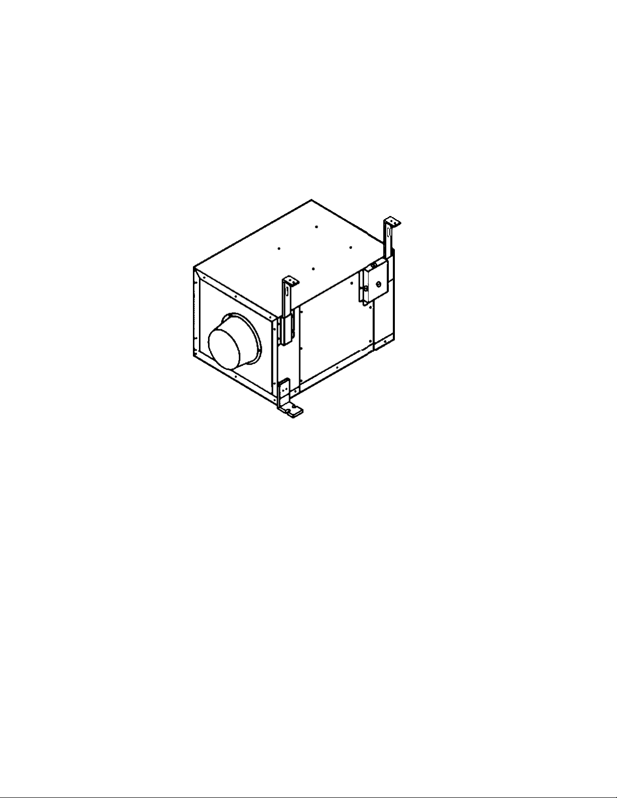
IN-LINE Fan
FV-10NLF1 FV-20NLF1
FV-30NLF1 FV-40NLF1
Panasonic
READ AND SAVE THESE INSTRUCTIONS
Please read the instrix:tkxis carefuly before atteripting to install.operate
or service the Panasonic IN-LINE Fan. Failure to comply with instructions
could result in personal injury and/or property damage. Please retain
for future reference.
Table of Contents
Supplied Accessories
Description__________________________________________________________
Dimensions_________________________________________________________
Specifications________________________________________________________
Unpacking__________________________________________________________
General Safety Information
Installation I (Horizontally Between Joists)
Installation II (On Ceilings/Joists).........................
Installation III (Vertically On Joists Or Pillars).
Mai ntenance
Product Service
_____________________________
__________________________________________________
____________
_________
......
___________________________
Pages
2
2
3
3
3
4
5-6
7
6
9
9
Page 2

SUPPLIED ACCESSORIES
FV-10NLF1 FV-20NLF1 FV40NLF1 FV-40NLF1
Part name
Bracket 2
Hartger 1
Bracket cover
Installation bracket 2
Extension bracket 2
Holder
(AssernOM on body)
Illustration
Quantity
2
2
Long screw
Self-tapping screw
Short screw
ec?
10
12
4
DESCRIPTION
These Panasonic IN-LINE Fan models use a sirocco fan driven by a capacitor motor.
The motor is designed to have an extended service life with reduced energy consumption, and a reduced noise level.
It also incorporates a thermal cutout for safety.
Page 3
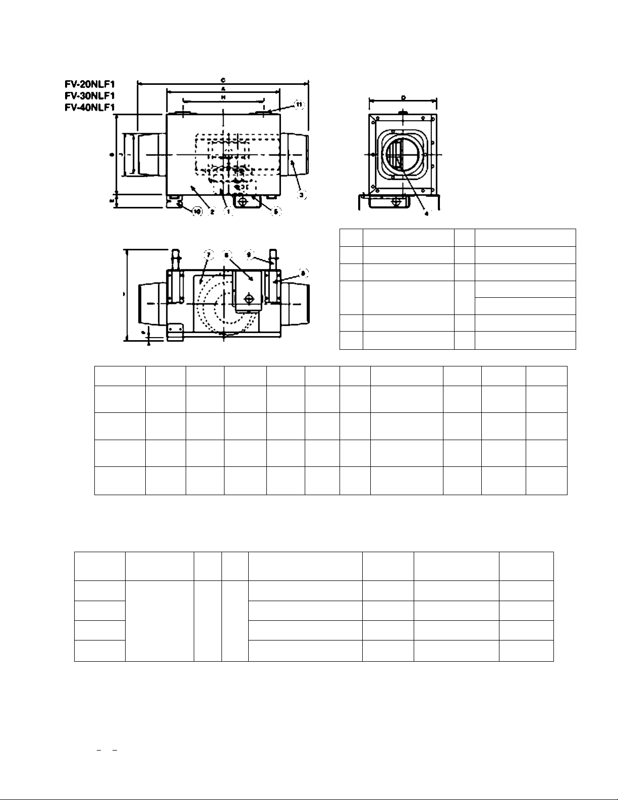
DIMENSIONS
FV-10NLF1
mnotf
Model No.
F\LtONLF1
FV«)NLF1
F>A30NLP1
F\M0NLF1
<13 3«)
<13 3«)
(1511«2)
<16 17«3)
A
340
340
300
430
B c 0 e
240
(9 7/16)
240
(9 7/16)
270
(105«)
340
<13 3«)
440
<17 S/16)
560
(21 21/32)
600
(23 5«)
S60
(221/16)
200
(7 7«)
240
<9 7/1«
260
<11 1/32)
260
(11 1/32)
36.1
(1 1«)
36.1
(1 1/2)
36.1
(1 1/2)
36.1
(1 1/2)
No.
F
8
(S/16)
a
(5/16)
6
(8/16)
6
(5/16)
Part name
Motor inspection panel
Body
Adapter
Ftn
Junction box
Jurtctlon box covor
Q
321^1
(12 5«-22 7«)
321-621
<12 5«-24 7/16)
321-661
(12 5«-26)
321-661
(12S«-26)
No. Pari rtame
Brack«« cov«r
®
installation bracket
Extension bracket
Bracket
Holder
H
242
(917/32)
242
(9 17/32)
242
(9 17/32)
242
(917/32)
<07 11/16)
1 j
097
(43 13^6)
0142
(06 19«)
0142
<06 19«2)
0195
0112
^13«2)
0156
(06 7/32)
0156
(06 7/32)
0211
(065^6)
SPECIFICATIONS
Model No.
FV-10NLF1
FV-20NLF1
FV-30NLF1 96 1340 340
FV-40NLF1
* Power consumption, speed and elr deivery vakiee have been measured at 6mm WQ (0^ WQ).
Air direction
Exhaust
Hz Power consumption
V
120 60
UNPACKING
Unpack and carafully remove unit from carton
Re^er to the eiypfcod accesaonea list to venfy that all parts are preserrt
(W)
36 1590 120 6^13.9)
57 1260 240 7.5(16.5)
132 1150 440 11.9(26.3)
Speed
(RPM)
Air delivery
(CFM)
Weigni
kg (lb.)
10.9(24.1)
Page 4

GENERAL SAFETY INFORMATION
1. Do not install this IN-LINE Fan wt>ere the temperature may exceed 6C ^140 T).
2. Make certain that the service supply voltage is 120V. 6OH2.
3. Follow all local electrical and satety codes as well as the National Electrical Code (NEC) and the
Occupation Safety and Health Act (OSHA).
4. Always switch the power source off before workirtg 00 or near the fan or motor.
3. Protect the elecincal wires from sharp edges, os. grease, hot surlace$. chemicals, or other objects.
6. Do not bend the electrical wires.
7. Do not install the unit where ducts are configured as shown In Fig.A.
8. Provide suctiort parts with proper ventilatioo.
9. This unit is aoceptabid for use over a bathtx^ or shower when installed In a OFCi protected branch
circuit.
CAUTION
1. For genorai veniiiaiing uaa only. Do r>ot usa lo axhaust
hazardous or explosiva maiariais or vapours.
2. Not lor usa in cooking araas.<Pig.B)
Œ
(CoownovM)
Oònoi ir*u0 aboyt
crfMettWMa
FI9.A
9. Thia produci rnuai bo grourtdod.
4. Before insiaitation, confirm ihai the unit is facing the right
direction. <Fig.C)
5. Do not drop the unit, put it on the hanger securely.
WARNING
To reduce the risk of fire, electric shock or personal injury, observe the following;
A. Use this ur^t oniy in the manner intended by the manufacturer, if you have any questions, contact the manu
facturer.
B. Instailation work artd eiectricai wirir>g must be done by quaiified person(s) in accordance with ali appiicabie
codes and starvjards. irKiuding fire-rated construction.
C. Sufficient air is needed tor proper combustion and exhausting of ^ses through the flue (chimney) of fuel burning
equipment to prevent backdratbng. Foftow the heating equipment manufacturei^ guidelines and safety standards
such as those published by the National Fire Protection Association (NFPA), the American Society for Heat
ing Refrigeration and Air Conditioning Engir>eers (ASHRAE) and the local code authorities.
D. When cutting or drilling into a wall or ceiling, do not damage efe:irical wiring and other hidden utilities.
E. Ducted fans must always be vented to the outdoors.
F. If this unit IS to be irtstalled over a tub or shower, it must be marred as intended tor thés application.
0. Do not use this unit with any soM-state oorttrol device.
H. Before servicing or cleaning unit, switch power off at service panel and took the service disconnecting mains to
prevent power from being switched on accidentaffy. When the service disconnecting mains cannot be locked,
securety, fasten a promirtent warning device, such as a tag. to tie service panel.
1. NEVER place a switch where it can be reached from a tub or shower.
Page 5

INSTALLATION I (horizontally between joists)
1. Di$conodct the power to the receptacle before starting
the installation.
2. Fix the hanger to the ceiling joist. Keep distance ’ A "
between the hanger and ceiling board (table 1). Use two
long screws to fasten the hanger. (Flg.1)
Dintension: mm(inch)
MODEL lONLFI 20NLFI MNLR 40NLFI
A
165
(6|)
3. After confirming the direction that the unit will be facing,
attach the bracket and bracket cover to the unit with selftappeig screws. (Rg.2)
165
(6|)
(table 1)
185
(7|)
215
(8|>
CAUTION
The holder was assembled on the back side of the unit,
(no shown in Fig,2)
Attach the unit body hortzontaty to the panel of you choice.
For best results, the bracket ar>d bracket cover should be
attached vertically. The holder and the bracket should be
irtstalled on the same side of the joist.
4. Insert Installation bracket into bracket cover.
If joist space is greater than distance B at the eerier (table
2), attach installation bracket and extension bracket as
shown below.
MODEL lONLFI
B
S.
Insert the holder, located on the unit, into the hanger.
381
(15)
20NLFI
421
(16|) (18|) (18|)
(table 2)
Dimension: mm(inch)
MNLR 40NLFI
461 461
Page 6

INSTALLATION I (horizontally between joists)
6. Attach the IN-LINE Fan to a ioisi or a pillar with the
kmg $crew$. (Fig.4)
7. Remove iunclion box cover and secure cortduii or wire
holder to jurwtion box cover krx>ckout hole. {Fig.S)
8. Usirtg wire rtuts. connect house power wire as shown
in the wictng diagram.
9. Replace junction box cover.
CAUTION
Mount Junction box cover carefully so that wires are
not pinched.
Wiring Diagram
10. Install orcuiar ducts (on both endsj and secure them
with tape or ciampe.
Consult table 3 for the appropriate duct sizes.
Oimertsion: mm{ir>ch)
MODEL 10NLFI 20NLFI 30NLFI 40NLR
duct 0
11. Connect power ine to receptacle after (lnishir>g duct work.
102 152 152
(4)
(6) (6) (8)
(table 3)
203
Page 7

INSTALLATION II (ON CEILINGS/JOISTS)
1. Attach installation bracket and bracket to the unit body.
(Fig.6>
CAUTION
Inserì the installation bracket into the bracket covef
attached to the panel.
2. Extend installation bracket and put the unK on the ceiling
or (oist Secure with long screws. (Fig.7)
OreUarduci
UTQ SOW
3. Remove junction box cover and secure oornkiit or wire
holder to jur>ction box cover knockout hole. (Fig.S)
4. Using wire nuis< connect house power wire as shown in
the wihr^ diagram on page 6.
CAUTION
Mount junction box oovor caretutty so that wires are rxM
pinched.
S. Install circular ducts (on both ends) and secure №em
with tape or clamps.
ConsuR table 3 for the appropriate duct sues.
Olmertsion: mm(ir>ch)
vlortQ icrtw
MODEL
duc t 0
10NLFI
102 1 52 152
(4)
20NLFI 30NLFI
(6) (6) (8)
(table 3)
40NLR
203
Page 8

INSTALLATION III (VERTICALLY ON JOISTS OR PILLARS)
Installing the IN-LINE Fan requires an accessible area (attic or
a«r extraction apparatus)
1. Install the IN-LINE Fan using the first step deechbed in
INSTALLATION II.
2. Extend insialation bracket arxl hang the unit on the joist
or piller. Fix with the long screws. (Fig.8)
CAUTION
Be careful not to drop the unit.
3. Remove junction box cover and secure conduit or wire
holder to junction box cover knockout hole. (Fig.S)
4. Using wire nuts, connect house power wire as shown in
the wiring diagram.
CAUTION
Mount junction box cover carefully so that wires are not
pinched.
wiring Diagram
5. irtstall circular ducts (on both ends) and secise them
with tape or clamps.
Consult table 3 for the appropriate duct sizes.
Dimension: mm(inch
MODEL 10NLR 20NLFI 30NLFI 40NLR
duct 0
102 152 152
(4)
(6) (6) (8)
(table 3)
203
8
Page 9

MAINTENANCE
WARNING
Disconnect power line betcxe procee<)íng with repairs or
maint6r>ance.
CAUTION
1. Never use beniene based thinner or similaf chemicals
lor cleaning the 114-LINE Fan.
2. Do noi alow water to come imo contact with the motor.
3. Do not immerse resin parts in water where the
temperature is over 60^(140
1. Remove inspection panel (take off the screws and pull).
(Rq-S)
2. Clean nspecbon panel (do not immerse In water), wipe dry
w^h cloth.
3. Remove dust and dirt inside the fen’s body using a vacuum
cioonor. (Fig. 10)
4. Using a doth dampened with kitchen detergent, remove
any din from the fan^ body. Wpe dry with a doth (do not wipe
thermal insulation parts inside body with dampened doth).
5. Replace inspection panel.
PRODUCT SERVICE
Warning concerning removal of covers.
The unit should be serviced by qualified techniodns only. No service iniormation is provided for customers. Your product is designed
and manufactured to ensure a minimum of maintenance. However, should ycur unit ever require service, a nationwide system of
factory service centers arxJ AUTHORIZED INDEPENDENT SERVICE CENTf ES is mairvtained to support your product*s warranty.
(In tr>e u.S A.can 1-66^545*2672 to locate the Panasonic Authorired Servtca Center nearest you.)
PANASONIC CONSUMER ELECTRONICS COMPANY
One Panasonic Way. Secaucus, NJ 07094. USA http;//www,panasonlc.com
PANASONIC CANADA INC.
5770 Ambler Drive. Mississauga. Ontario L4W 2T3. CANADA http;//wyw.panasonic.ca
KNLftOrM S0M8-0
 Loading...