

Panasonic EYFLA4A, EYFLA5A, EYFLA5AR, EYFLA5Q, EYFLA5B Operating Instructions Manual
...
Cordless Impact Driver/Cordless Impact Wrench
Akku-Schlagschrauber
Perceuse à impact sans l/Clé de serrage à impact sans l
Avvitatore ad impulsi senza li/Chiave ad impulsi senza li
Snoerloze slagschroevendraaier/Snoerloze slagmoersleutel
Destornillador de impacto inalámbrico/Llave de impacto inalámbrica
Akku-slagboremaskine/Akku-slagnøgle
Sladdlös slagskruvdragare/Sladdlös slagskruvnyckel
Trådløs slagbormaskin/Trådløs slagnøkkel
Langaton iskuruuviavain/Langaton iskuavain
Bezprzewodowa wkrętarka udarowa/Bezprzewodowy klucz udarowy
Kablosuz Darbeli Tornavida/Kablosuz Darbeli Anahtar
Ударный аккумуляторный шуруповерт/Ударный аккумуляторный гайковерт
Ударний акумуляторний шуруповерт/Ударний акумуляторний гайковерт
Bezdrátový elektrický utahovák / Bezdrátový nárazový šroubovák
Before operating this unit, please read these instructions completely and save this manual for future use.
Vor Inbetriebnahme des Gerätes die Betriebsanleitung bitte gründlich durchlesen und diese Broschüre zum späteren Nachschlagen sorgfältig aufbewahren.
Lire entièrement les instructions suivantes avant de faire fonctionner l’appareil et conserver ce mode d’emploi à des fins de consultation ultérieure.
Prima di usare questa unità, leggere completamente queste istruzioni e conservare il manuale per usi futuri.
Lees deze gebruiksaanwijzing aandachtig door voor u het apparaat in gebruik neemt en bewaar de gebruiksaanwijzing voor eventuele naslag.
Antes de usar este aparato por primera vez, lea todas las instrucciones de este manual y guarde el manual para poderlo consultar en el futuro.
Gennemlæs denne betjeningsvejledning før brugen og gem den til fremtidig brug.
Läs igenom hela bruksanvisningen innan verktyget tas i bruk. Spara bruksanvisningen för senare användning.
Før enheten tas i bruk, vennligst les disse alle anvisningene og oppbevar deretter bruksanvisningen for senere bruk.
Lue ohjeet huolella ennen laitteen käyttöönottoa ja säilytä tämä käyttöohje tallessa tulevaa tarvetta varten.
Przed uruchomieniem urządzenia należy przeczytać w całości niniejszą instrukcję i zachować ten podręcznik do użytku w przyszłości.
Bu cihazı kullanmaya başlamadan önce, lütfen bu talimatları tam olarak okuyun ve ileride başvurmak üzere bu kılavuzu saklayın.
Перед эксплуатацией данного устройства, пожалуйста, полностью прочтите данную инструкцию и сохраните данное руководство для использования в будущем.
Перед екплуатацiєю даного пристрою, будь ласка, повнiстю прочитайте дану iнструкцiю i збережiть даний посiбник для використання у майбутньому.
Před použitím tohoto nástroje si, prosím, pročtěte veškeré instrukce a návod k obsluze si uchovejte pro budoucí použití.
Operating Instructions
Bedienungsanleitung
Instructions d’utilisation
Istruzioni per l’uso
Gebruiksaanwijzing
Manual de instrucciones
Brugsvejledning
Driftsföreskrifter
Bruksanvisning
Käyttöohjeet
Instrukcja obsługi
Kullanım Talimatları
Инструкция по эксплуатации
Iнструкцiя з експлуатації
Návod k obsluze
Model No: EYFLA4A / EYFLA4AR
EYFLA5A / EYFLA5AR
EYFLA5Q / EYFLA5QR
EYFLA5B
EYFLA6J / EYFLA6JR
EYFLA6B
EYFMA1J / EYFMA1JR
EYFMA1B
* Pictured: Cordless impact driver
* Abgebildet: Akku-Schlagschrauber
* Image: Perceuse à impact sans l
* Nell’immagine: Avvitatore ad impulsi senza li
* Afgebeeld: Snoerloze slagschroevendraaier
* En la imagen: Destornillador de impacto inalámbrico
* Billedet viser: Akku-slagskruetrækker
* På bild: Sladdlös slagskruvdragare
* Avbildet: Trådløs slagdriver
* Kuvassa: Langaton iskuavain
* Na ilustracji: Bezprzewodowa wkrętarka udarowa
* Resim: Kablosuz darbeli tornavida
*
На рисунке: Ударный аккумуляторный шуруповерт
*
На малюнку: Ударний акумуляторний шуруповерт
* Zobrazení: Bezdrátový elektrický utahovák
-
2 -
Index/Index/Index/Indice/Index/Indice/Indeks/Index/Indeks/Hakemisto/Indeks/Dizin/Индекс/Індекс/Index
English: Page 6 Norsk: Side 119
Deutsch: Seite 20 Suomi: Sivu 133
Français: Page 34 Polski: Strona 146
Italiano: Pagina 48 Türkçe: Sayfa 160
Nederlands: Bladzijde 62 Русский: Страница 173
Español: Página 76 Українська: Сторiнка 187
Dansk: Side 91 Czech: Česky 201
Svenska: Sid 105
FUNCTIONAL DESCRIPTION
FUNKTIONSBESCHREIBUNG
DESCRIPTION DES FONCTIONS
DESCRIZIONE DELLE FUNZIONI
FUNCTIEBESCHRIJVING
DESCRIPCIÓN FUNCIONAL
FUNKTIONSBESKRIVELSE
FUNKTIONSBESKRIVNING
FUNKSJONSBESKRIVELSE
TOIMINTAKUVAUS
OPIS FUNKCJI
İŞLEVSEL AÇIKLAMA
ФУНКЦИОНАЛЬНОЕ ОПИСАНИЕ
ФУНКЦIОНАЛЬНИЙ ОПИС
POPIS FUNKCÍ
(G)(H)
(I)
(M)
(N)
(O)
(L)
(P)
(U)
(T)
(Q)
(S)
(R)
(B)
EYFLA5Q
EYFLA5QR
EYFLA5B
(A)
(C)
(D)
(E)
(F)
(J)
(K)
EYFLA4A
EYFLA4AR
EYFLA5A
EYFLA5AR
Remote control and battery are not included.
Fernbedienung und Batterie werden nicht mitgeliefert.
La télécommande et la batterie ne sont pas incluses.
Telecomando e batteria non in dotazione.
Afstandsbediening en batterij zijn niet bijgeleverd.
El control remoto y la batería no están incluídos.
Fjernbetjening og batteri medfølger ikke.
Fjärrkontroll och batteri medföljer ej.
Fjernkontroll og batteri er ikke inkludert.
Kaukosäädin ja paristo eivät kuulu varusteisiin.
Zestaw nie zawiera zdalnego sterowania i akumulatora.
Uzaktan kumanda ve pil dahil değildir.
Пульт дистанционного управления и батарея не входят в комплект.
Пульт дистанційного управління і батарея не входять до комплекту.
Dálkové ovládání a baterie nejsou obsaženy v balení.
EYFLA6J
EYFLA6JR
EYFLA6B
EYFMA1J
EYFMA1JR
EYFMA1B

-
3 -
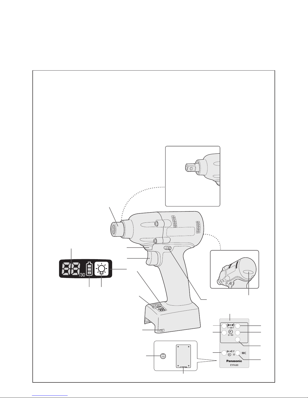
(A)
6.35 mm (1/4") hex quick connect chuck (EYFLA4A, EYFLA4AR, EYFLA5A, EYFLA5AR)/square drive (EYFLA5Q,
EYFLA5QR, EYFLA6J, EYFLA6JR, EYFMA1J, EYFMA1JR/Pin type, EYFLA5B, EYFLA6B, EYFMA1B/Ball detent type)
6,35 mm (1/4") Sechskant-Schnellaufspannfutter (EYFLA4A, EYFLA4AR, EYFLA5A, EYFLA5AR)/Vierkant (EYFLA5Q,
EYFLA5QR, EYFLA6J, EYFLA6JR, EYFMA1J, EYFMA1JR/Stifttyp, EYFLA5B, EYFLA6B, EYFMA1B/Kugelrastentyp)
Mandrin de connexion rapide hexagonal de 6,35 mm (1/4") (EYFLA4A, EYFLA4AR, EYFLA5A, EYFLA5AR)/entraînement carré (EYFLA5Q,
EYFLA5QR, EYFLA6J, EYFLA6JR, EYFMA1J, EYFMA1JR/Type à goujon, EYFLA5B, EYFLA6B, EYFMA1B/Type à détente à bille)
Mandrino esagonale di collegamento rapido da 6,35 mm (1/4") (EYFLA4A, EYFLA4AR, EYFLA5A, EYFLA5AR)/attacco quadro (EYFLA5Q,
EYFLA5QR, EYFLA6J, EYFLA6JR, EYFMA1J, EYFMA1JR/Tipo con piolo, EYFLA5B, EYFLA6B, EYFMA1B/Tipo con sfera di arresto)
6,35 mm zeskantboorkop met snelkoppeling (EYFLA4A, EYFLA4AR, EYFLA5A, EYFLA5AR)/vierkante aandrijving (EYFLA5Q,
EYFLA5QR, EYFLA6J, EYFLA6JR, EYFMA1J, EYFMA1JR/pen-type, EYFLA5B, EYFLA6B, EYFMA1B/Arreteerkogel-type)
Mandril hexagonal de conexión rápida de 6,35 mm (1/4") (EYFLA4A, EYFLA4AR, EYFLA5A, EYFLA5AR)/Excitador cuadrado (EYFLA5Q,
EYFLA5QR, EYFLA6J, EYFLA6JR, EYFMA1J, EYFMA1JR/tipo pasador, EYFLA5B, EYFLA6B, EYFMA1B/tipo parada de bola)
6,35 mm (1/4") hexagonal borepatron til hurtig tilslutning (EYFLA4A, EYFLA4AR, EYFLA5A, EYFLA5AR)/rkantet drev
(EYFLA5Q, EYFLA5QR, EYFLA6J, EYFLA6JR, EYFMA1J, EYFMA1JR/stifttype, EYFLA5B, EYFLA6B, EYFMA1B/Kuglelåstype)
Snabbchuck med 6,35 mm sexkantshylsa (EYFLA4A, EYFLA4AR, EYFLA5A, EYFLA5AR)/fyrkantskoppling (EYFLA5Q,
EYFLA5QR, EYFLA6J, EYFLA6JR, EYFMA1J, EYFMA1JR/stifttyp, EYFLA5B, EYFLA6B, EYFMA1B/typ med kulspärr)
6,35 mm (1/4") hex hurtigtilkoplingschuck (EYFLA4A, EYFLA4AR, EYFLA5A, EYFLA5AR)/rkantdrev (EYFLA5Q, EYFLA5QR,
EYFLA6J, EYFLA6JR, EYFMA1J, EYFMA1JR/pinnetype, EYFLA5B, EYFLA6B, EYFMA1B/Drev med kulelåsing)
6,35 mm (1/4") kuusiopikaistukka (EYFLA4A, EYFLA4AR, EYFLA5A, EYFLA5AR)/neliöavain (EYFLA5Q, EYFLA5QR,
EYFLA6J, EYFLA6JR, EYFMA1J, EYFMA1JR/nastatyyppi, EYFLA5B, EYFLA6B, EYFMA1B/Kuulan pidättimen tyyppi)
6,35 mm (1/4") uchwyt hex (EYFLA4A, EYFLA4AR, EYFLA5A, EYFLA5AR)/Kwadratowa końcówka (EYFLA5Q, EYFLA5QR,
EYFLA6J, EYFLA6JR, EYFMA1J, EYFMA1JR/Typ wtyk, EYFLA5B, EYFLA6B, EYFMA1B/Typ rygiel kulowy)
6,35 mm (1/4") altıgen hızlı bağlantılı başlık (EYFLA4A, EYFLA4AR, EYFLA5A, EYFLA5AR)/kare tornavida (EYFLA5Q,
EYFLA5QR, EYFLA6J, EYFLA6JR, EYFMA1J, EYFMA1JR/Pim tipi, EYFLA5B, EYFLA6B, EYFMA1B/Bilye mekanizmalı tip)
6,35 мм (1/4") шестигранный патрон быстрого подсоединения (EYFLA4A, EYFLA4AR, EYFLA5A, EYFLA5AR)/квадратный хвостовик (EYFLA5Q,
EYFLA5QR, EYFLA6J, EYFLA6JR, EYFMA1J, EYFMA1JR/Штифтового типа, EYFLA5B, EYFLA6B, EYFMA1B/С шариковым фиксатором)
6,35 мм (1/4") шестигранний патрон швидкого приєднання (EYFLA4A, EYFLA4AR, EYFLA5A, EYFLA5AR)/квадратний хвостовик (EYFLA5Q,
EYFLA5QR, EYFLA6J, EYFLA6JR, EYFMA1J, EYFMA1JR/Штифтового типу, EYFLA5B, EYFLA6B, EYFMA1B/З шариковим фіксатором
)
6,35 mm (1/4“) Svěrací šroub s vnějším šestihranným nástavcem (EYFLA4A, EYFLA4AR, EYFLA5A, EYFLA5AR)/ vnitřní čtyřhran (EYFLA5Q,
EYFLA5QR, EYFLA6J, EYFLA6JR, EYFMA1J, EYFMA1JR/ typ s kontaktním kolíkem, EYFLA5B, EYFLA6B, EYFMA1B/ Typ s kuličkovou aretací)
(B)
Tightening conrmation lamp
Anzugsbestätigungslampe
Témoin de conrmation de serrage
Spia conferma serraggio
Aanhaaltoestand-bevestigingslampje
Lámpara de conrmación de apriete
Lampe til bekræftelse af stramning
Lampa för bekräftad åtdragning
Strammebekreftelseslampe
Kiristyksen varmistuslamppu
Lampka potwierdzenia dokręcenia
Sıkma onay lambası
Лампочка подтверждения затяжки
Лампочка підтвердження затяжки
Kontrolka utažení
(C)
Forward/Reverse lever
Vorwärts-/Rückwärtshebel
Levier d’inversion marche avant/marche arrière
Leva di avanzamento/inversione
Links/rechtsschakelaar
Palanca de avance/marcha atrás
Greb til forlæns/baglæns retning
Riktningsomkopplare
Forover-/bakoverbryter
Eteenpäin/taaksepäin vipu
Dźwignia biegu do przodu/wstecznego
İleri/Geri kolu
Рычаг переключения вперед/назад
Важіль перемикання вперед/назад
Spínač předního a zpětného chodu
(D)
Alignment mark
Ausrichtmarkierungen
Marques d’alignement
Marcature allineamento
Uitlijntekens
Marcas de alineación
Flugtemærker
Anpassningsmärken
Opprettingsmerke
Sovitusmerkit
Znak ustawczy
Hizalama işareti
Метки совмещения
Мітки вирівнювання
Značka zarovnání
(E)
Remote control receiver
Fernbedienungsempfänger
Récepteur de la télécommande
Ricevitore telecomando
Afstandsbedieningontvanger
Receptor de control remoto
Fjernbetjeningsmodtager
Fjärrstyrningsgivare
Fjernkontrollmottaker
Kaukosäätimen vastaanotin
Odbiornik zdalnego sterowania
Uzaktan kumanda alıcısı
Датчик дистанционного управления
Датчик дистанційного управління
Přijímač signálu dálkového ovládání

-
4 -
(F)
Control panel
Bedienfeld
Panneau de commande
Pannello di controllo
Bedieningspaneel
Panel de control
Kontrolpanel
Kontrollpanel
Kontrollpanel
Säätöpaneeli
Panel sterowania
Kontrol paneli
Панель управления
Панель управління
Kontrolní panel
(G)
LED light on/off button
LED-Leuchten-EIN/AUS-Taste
Bouton Marche/Arrêt de la lumière DEL
Tasto di accensione e spegnimento della luce LED
Aan/uit-toets (ON/OFF) voor LED-lampje
Botón ON/OFF de luz LED
TÆND/SLUK-knap til LED-lys
Strömbrytare för LED-ljus
PÅ/AV-knapp for LED-lys
LED-valon kytkin/katkaisupainike
Przycisk włączania/wyłączania diody LED
LED ışık açma/kapama düğmesi
Кнопка включения/выключения светодиодной подсветки
Кнопка ввімкнення/вимкнення світлодіодного підсвічування
Spínač zap./vyp. elektroluminiscenční diody LED
(H)
Battery indication lamp
Akku-Anzeigelampe
Témoin indicateur de la batterie
Spia livello batteria
Accu-indicatielampje
Lámpara de indicadora de la batería
Batteriindikatorlampe
Batteriindikator
Batteriindikasjonslampe
Akun osoituslamppu
Wskaźnik poziomu mocy akumulatora
Pil gösterge lambası
Индикаторная лампочка батареи
Індикаторна лампочка батареї
Kotrolka stavu baterie
(I)
Display
Anzeige
Afchage
Display
Display
Visor
Display
Indikeringsfönster
Display
Näyttö
Ekran
Ekran
Дисплей
Дисплей
Displej
(J)
Variable speed control trigger
Variabler Geschwindigkeitskontrollschalter
Gâchette de commande de vitesse
Grilletto di controllo velocità variabile
Startschakelaar met variabele toerentalregeling
Disparador del control de velocidad variable
Kontroludløser for variabel hastighed
Avtryckare med variabel varvtalsreglering
Trinnløs hovedbryter
Nopeudensäätökytkin
Zapadka regulacji prędkości obrotowej
Değişken hız kontrol tetiği
Переключатель регулировки переменной скорости
Перемикач регулювання змінної швидкості
Spoušť rychlostní regulace
(K)
LED light
LED-Leuchte
Lumière DEL
Luce LED
LED-lampje
Luz indicadora
LED-lys
LED-ljus
LED-lys
LED-valo
Dioda LED
LED ışık
Светодиодная подсветка
Світлодіодне підсвічування
Světlo LED
(L)
Remote control
Fernbedienung
Télécommande
Telecomando
Afstandsbediening
Control remoto
Fjernbetjening
Fjärrkontroll
Fjernkontroll
Kaukosäädin
Zdalne sterowanie
Uzaktan kumanda
Пульт дистанционного управления
Пульт дистанційного управління
Dálkové ovládání
(M)
+ button
Taste +
Bouton +
Tasto +
+ toets
Botón +
+ knap
Knapp (+)
+ knapp
+ painike
Przycisk +
+ düğmesi
Кнопка +
Кнопка +
Tlačítko +

-
5 -
(N)
− button
Taste –
Bouton −
Tasto −
− toets
Botón
−
− knap
Knapp (−)
− knapp
− painike
Przycisk −
− düğmesi
Кнопка −
Кнопка −
Tlačítko −
(O)
OK button
Taste OK
Bouton OK
Tasto OK
OK toets
Botón OK (correcto)
OK-knap
Bekräftelseknapp
OK knapp
OK-painike
Przycisk OK
Tamam düğmesi
Кнопка OK
Кнопка OK
Tlačítko OK
(P)
Torque level button
Anzugsmomentstufentaste
Bouton de niveau du couple de serrage
Tasto livello coppia
Aanhaalmoment-niveautoets
Botón de palanca de par de torsión
Knap til stramningsmomentniveau
Väljare för momentnivå
Dreiemomentknapp
Vääntömomentin tasopainike
Przycisk poziomu momentu obrotowego
Tork seviyesi düğmesi
Кнопка уровня крутящего момента
Кнопка рівня крутильного моменту
Tlačítko regulace hladiny točivého momentu
(Q)
Format button
Formattaste
Bouton de format
Tasto formato
Formatteertoets
Botón de formato
Formatknap
Formateringsknapp
Format knapp
Formaatin painike
Przycisk formatu
Biçim düğmesi
Кнопка формата
Кнопка формату
Rázové tlačítko
(R)
Holder
Halter
Support
Supporto
Houder
Retenedor
Holder
Hållare
Holder
Pidin
Uchwyt
Tutucu
Держатель
Держак
Držák
(S)
Battery
Batterie
Batterie
Batteria
Accu
Batería
Batteri
Batteri
Batteri
Akku
Akumulator
Pil
Батарея
Батарея
Baterie
(T)
Interval set button
Intervall-Einstelltaste
Bouton de réglage de l’intervalle
Tasto impostazione intervallo
Interval-insteltoets
Botón de ajuste de intervalo
Intervalindstillingsknap
Intervallinställningsknapp
Intervallinnstillingsknapp
Jakson säätöpainike
Przycisk regulacji interwału
Aralık ayar düğmesi
Кнопка установки интервала
Кнопка встановлення інтервалу
Tlačítko intervalového nastavení
(U)
Torque set button
Anzugsmoment-Einstelltaste
Bouton de réglage du couple de serrage
Tasto impostazione coppia
Aanhaalmoment-insteltoets
Botón de ajuste de par de torsión
Knap til indstilling af stramningsmoment
Momentinställningsknapp
Dreiemomentinnstillingsknapp
Vääntömomentin säätöpainike
Przycisk regulacji momentu obrotowego
Tork ayar düğmesi
Кнопка установки крутящего момента
Кнопка встановлення крутильного моменту
Tlačítko nastavení hladiny točivého momentu

-
6 -
Original instructions: English
Translation of the original instructions:
Other languages
I
. INTENDED USE
This tool is a Cordless Impact Driver/Wrench
and can be used to tighten bolts, nuts, and
screws. Additionally, it provides a torque control function that automatically stops tool operation when a preset load is reached to deliver
consistent tightening torque.
IMPROPER USE
The use of the tool other than INTENDED USE
is dangerous and must be avoided.
The tool must not be used for the purposes such
as the following;
•
to mix paint or building materials,
•
polishing, grinding, sharpening, engraving.
RESIDUAL RISK
Some residual risks remains even with proper
use of the tool such as the following;
•
contact with the rotating bit
•
contact with the sharp edges of material or
something.
Read “the Safety Instructions” booklet
and the following before using.
II
.
ADDITIONAL SAFETY
RULES
1
) Wear ear protectors when using the
tool for extended periods.
2) Be aware that this tool is always in an
operating condition, since it does not have
to be plugged into an electrical outlet.
3) When screwing or driving into walls, floors,
etc., “live” electrical wires may be encountered. DO NOT TOUCH THE HEX QUICK
CHUCK OR ANY FRONT METAL PARTS
OF THE TOOL! Hold the tool only by the
plastic handle to prevent electric shock in
case you screw or drive into a “live” wire.
4) Do NOT operate the Forward/Reverse
lever when the main switch is on. The battery will discharge rapidly and damage to
the unit may occur.
5) During charging, the charger may become
slightly warm. This is normal.
Do NOT charge the battery for a long period.
6) When storing or carrying the tool, set the
Forward/Reverse lever to the center position (switch lock).
7) Do not strain the tool by holding the speed
control trigger halfway (speed control
mode) so that the motor stops.
Symbol Meaning
V
Volts
Direct current
n
0
No load speed
… min
-1
Revolutions or reciprocations
per minutes
Ah
Electrical capacity of battery
pack
III
. ASSEMBLY
Attaching or Removing Bit
NOTE:
•
When attaching or removing a bit, disconnect battery pack from tool or place the
switch in the center position (switch lock).
1. Hold the collar of quick connect chuck and
pull it out from the tool.
2. Insert the bit into the chuck. Release the
collar.
3. The collar will return to its original position
when it is released.
4.
Pull the bit to make sure it does not come out.
5. To remove the bit, pull out the collar in the
same way.
CAUTION:
• If the collar does not return to its origi
nal position or the bit comes out when
pulled on, the bit has not been properly
attached. Make sure the bit is properly
attached before use.
EYFLA4A/EYFLA4AR/EYFLA5A/EYFLA5AR
12 mm
(15/32")
9 mm – 9.5 mm
(23/64" – 3/8")
6.35 mm
(1/4")
-
7 -
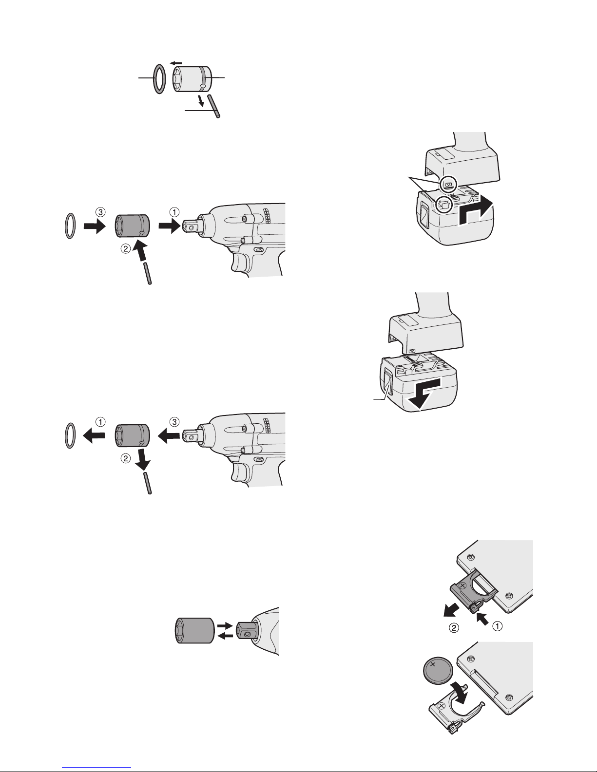
Attaching Socket (Pin type)
• Remove the socket’s rubber ring and pin.
rubber
ring
pin
groove
1 Attach the socket to the tool.
2 Insert the pin. (Taking care to align the pin
holes on the socket and tool.)
3 Attach the rubber ring by sliding it into place
over the groove.
NOTE:
Be sure to attach the rubber ring to prevent
the pin from falling out.
Removing Socket (Pin type)
1 Remove the rubber ring.
2 Remove the pin.
3 Remove the socket from the tool.
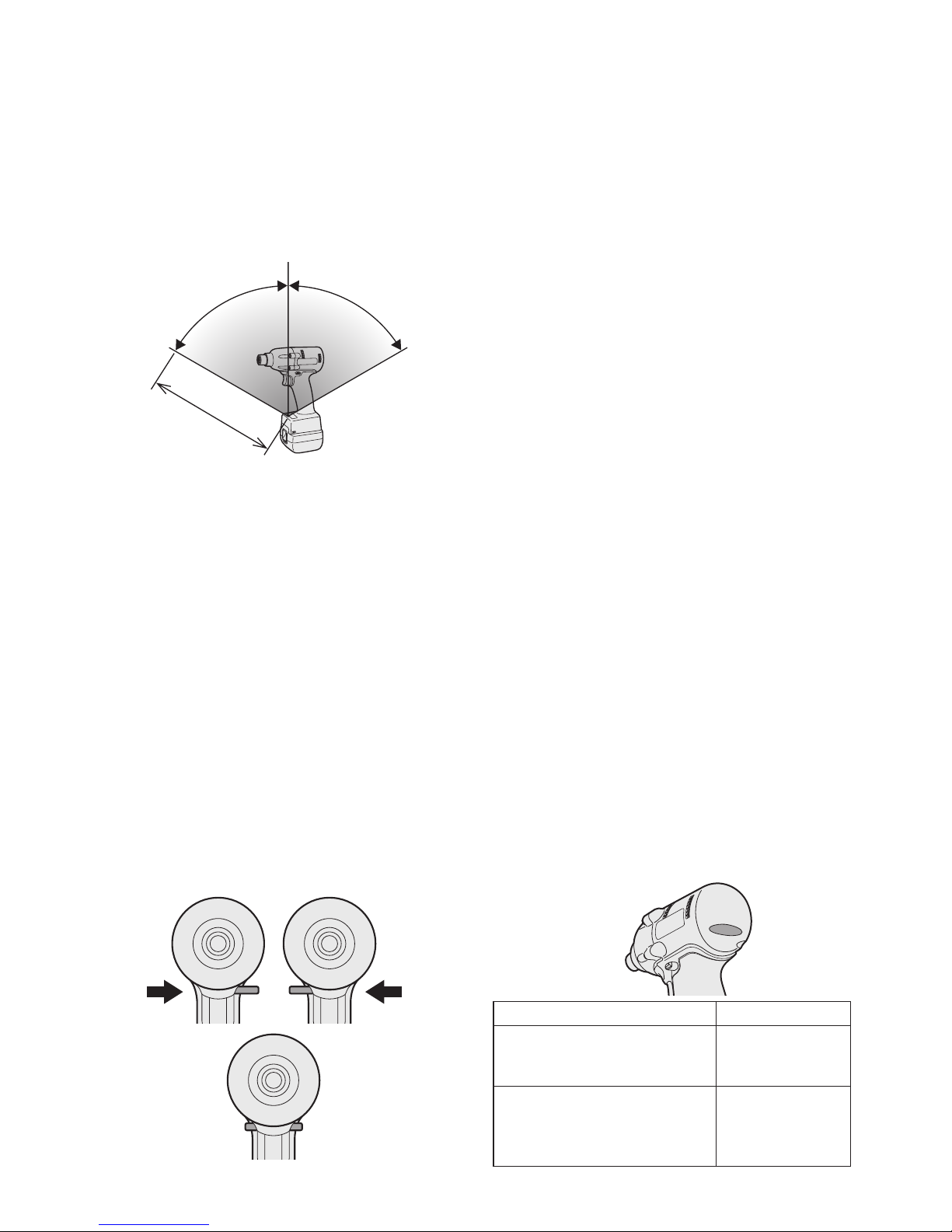
Attaching or Removing
Socket (Ball detent type)
1. Attaching Socket
Attach the socket by sliding the female
detent on the bottom of the socket to the
square drive on the body.
Make sure the
socket is firmly
connected to
the body.
2. Removing Socket
Pull out the socket.
Attaching or Removing Battery Pack
1. To connect the battery pack:
Line up the alignment marks and attach
the battery pack.
•
Slide the battery pack until it locks into
position.
Alignment
marks
2. To remove the battery pack:
Push up on the button from the front to release the battery pack.
Button
IV
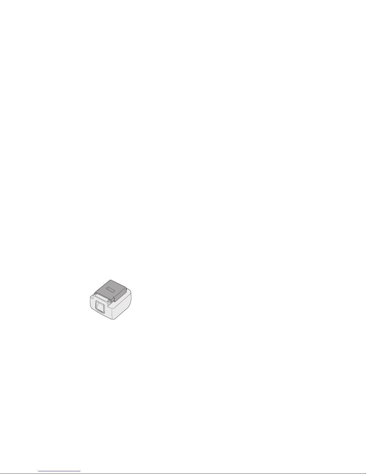
. OPERATION
Before Using the Remote
Control (Available as an
optional accessory)
Insert the battery
1. Pull out the battery holder.
1 Push in on the fas-
tener as indicated by
the arrow.
2 Pull out the holder.
2. Insert the bat
tery and push the
holder back in.
-
8 -
NOTE:
•
If the tool does not respond to the wireless
remote control even when the remote control is
operated close to the tool, the battery (CR2025)
is dead. Replace it with a fresh battery.
• The included battery is provided for sample use and may not last as long as commercially available batteries.
Wireless remote control range
Approx. 50 cm
Vertically
A
p
p
r
o
x
.
6
0
°
A
p
p
r
o
x
.
6
0
°
The remote control should be operated within
approximately 50 cm and approximately 60°
vertically and horizontally of the perpendicular
relative to the infrared receiver on the tool.
•
Under the following circumstances, you may not
be able to operate the tool, even within this range.
• If there is an object between the remote
control’s transmitter and the tool’s receiver.
• Use outdoors or in other environments
where the remote control receiver is
exposed to a strong light source, or when
the remote control transmitter or receiver is
dirty may cause the tool to fail to respond,
even when the remote control is used within
the operating range.
[Main Body]
Switch and Forward/Reverse
Lever Operation
Forward Reverse
Switch lock
CAUTION:
To prevent damage, do not operate
Forward/Reverse lever until the bit comes
to a complete stop.
Forward Rotation Switch
Operation
1. Push the lever for forward rotation.
2. Depress the trigger switch slightly to start
the tool slowly.
3. The speed increases with the amount of
depression of the trigger for efficient tightening of screws. The brake operates and
the bit stops immediately when the trigger
is released.
4. After use, set the lever to its center posi
-
tion (switch lock).
Reverse Rotation Switch
Operation
1.
Push the lever for reverse rotation. Check
the
direction of rotation before use.
2.
Depress the trigger switch slightly to start the
tool slowly.
3. After use, set the lever to its center position (switch lock).
CAUTION:
• To eliminate excessive temperature
increase of the tool surface, do not
operate the tool continuously using two
or more battery packs. Tool needs cool
off time before switching to another
pack.
Tightening confirmation lamp
• The tightening confirmation lamp can be
used to check whether the torque control
function was activated.
Tool status Lamp display
Tightening complete
(with torque control
function operation)
Green
(For approx. 2
seconds)
• Tightening not complete
• Tightening complete
with retightening within 1
second
Red
(For approx. 2
seconds)
-
9 -
The automatic stop
function has been
activated.
Red
(For approx. 5
minutes)
CAUTION:
• When the tool stops automatically after
the switch is released during impactmode tightening and then reengaged
within 1 second, the red lamp will light up
to indicate the risk of excessive torque
application as a result of retightening.
NOTE
• The tightening confirmation lamp will not
turn on under the following conditions:
• When the torque clutch is set to “F”
• During reverse rotation operation
• The lamp turns off when the tool is in
operation.
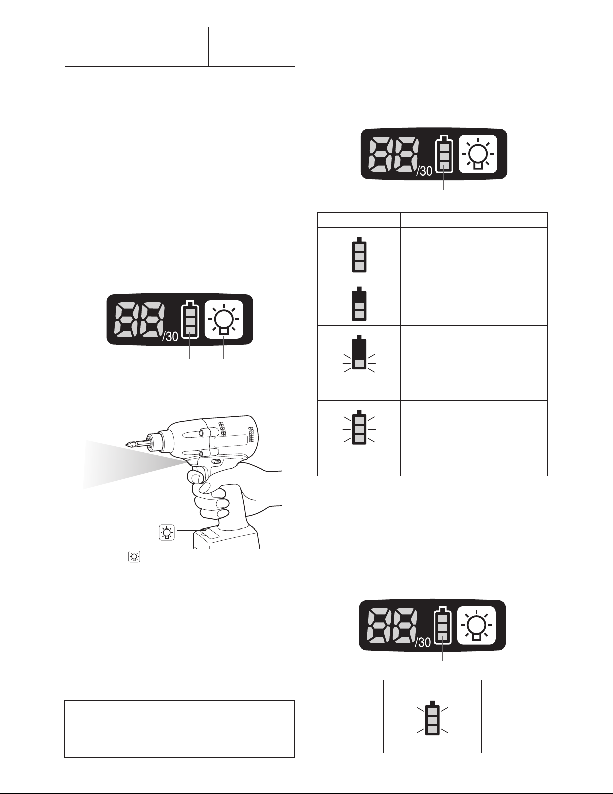
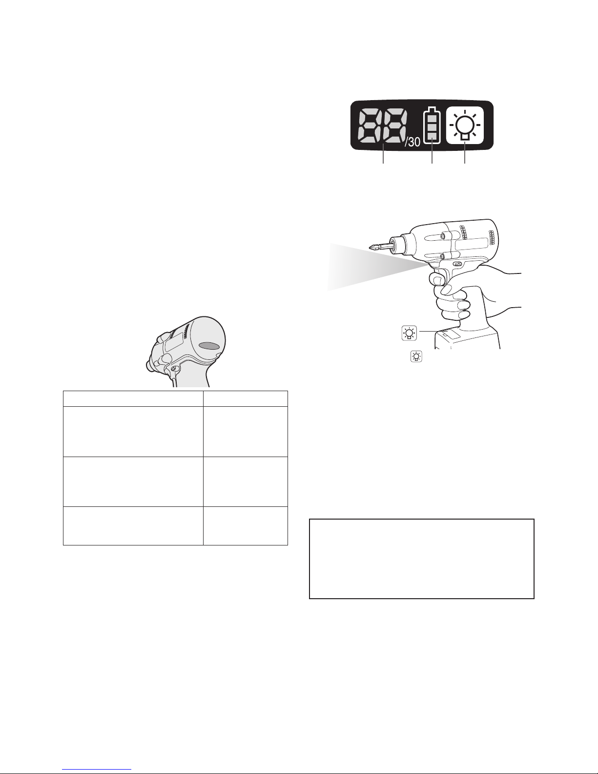
Control Panel
(1) (2) (3)
(1) LED light
Pressing the button toggles the LED light on
and off.
The light illuminates with very low current, and
it does not adversely affect the performance
of
the
tool during use or its battery capacity.
CAUTION:
•
The built-in LED light is designed to illuminate the small work area temporarily.
•
Do not use it as a substitute for a regular
flashlight, since it does not have
enough brightness
.
Caution : DO NOT STARE INTO BEAM.
Use of controls or adjustments or performance
of procedures other than those specied herein
may result in hazardous radiation exposure.
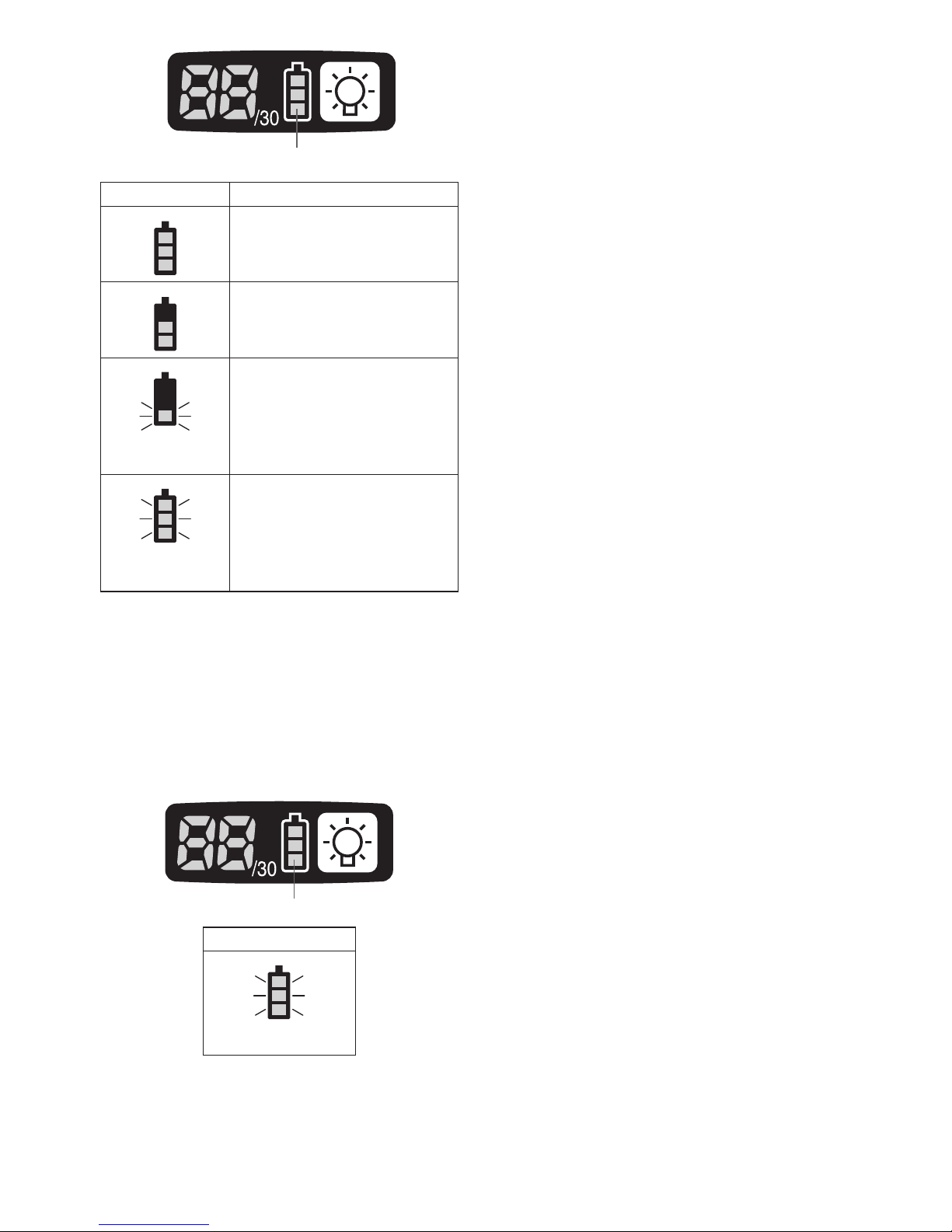
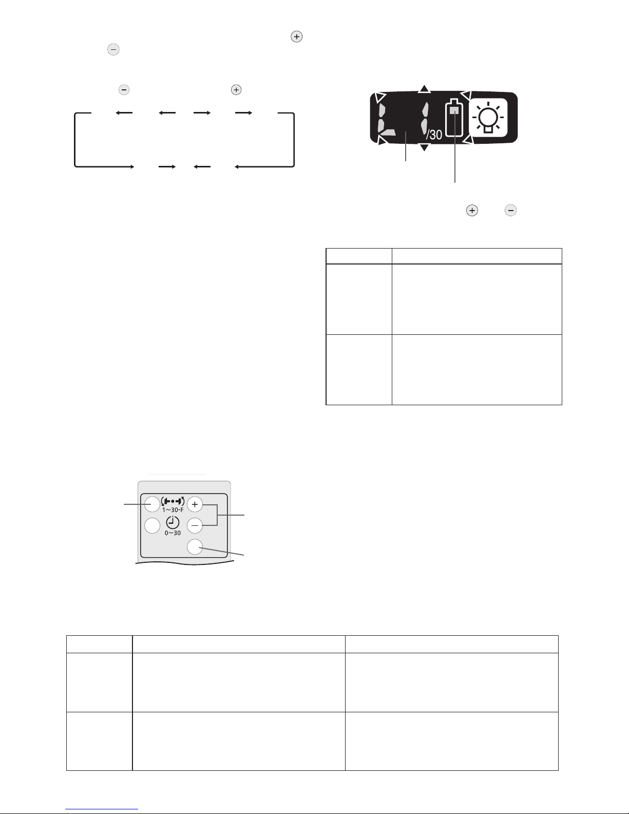
(2) The battery indication lamp
• Use the battery indication lamp to check
how much power is left in the battery.
• Battery life varies slightly with ambient temperature and battery characteristics. The
lamp is designed to provide a rough indication of remaining battery life.
Battery indication lamp
Indicator Battery status
Fully charged
Approx. 40% or less
remaining
Flashing
Flashing
Approx. 20% or less
remaining (indicates need
to recharge battery)
The battery pack will need
to be charged soon.
Flashing
No charge
The battery pack needs to
be charged.
(The tool’s automatic
power-off function will
activate at this stage.)
Automatic power-off function
• The automatic power-off function is designed
to prevent a loss of tightening torque due
to reduced battery voltage. Once it has
been activated, the tool will not operate until
the battery pack has been charged (or replaced with a fresh unit), even if the trigger is
depressed.
Battery indication lamp
Indicator
Flashing
-
10 -
NOTE:
• All 3 bars on the battery indication lamp
will flash when the automatic power-off
function is activated.
• When the battery indication lamp begins
flashing, the battery pack should be
charged (or replaced with a fresh unit)
immediately.
• Be sure to fully charge the battery pack
in question after activation of the automatic power-off function. Failure to do
so may prevent the automatic power-off
function from being properly deactivated.
(3) The torque control function
• The torque control function calculates the
load from the motor’s rotational angle during
the hammer impact and determines that the
bolt has been properly seated when a preset load value is exceeded. Driving is then
automatically stopped after a preset number
of impacts have been delivered to the bolt.
CAUTION:
•
Always check the tool’s tightening torque
before use. The required adjustment is
dependent on the type of threaded connection and can be best determined by practical trials. Check the trial screwings with a
torque wrench. Improper tool operation may
result in excessive or inadequate tightening.
• Always operate the tool with the switch
fully engaged. The torque control function will not operate when the switch is
not sufficiently engaged, preventing the
tool from stopping automatically.
• In work where a heavy load comes to
bear during tightening, the load may be
interpreted as the seating of the bolt,
preventing the bolt from being completely tightened.
• Repeated tightening of the same bolt
may break the bolt or deform the material into which the bolt is being driven as
a result of excessive tightening.
• The tightening torque value and preci
sion vary with factors such as the material into which the bolt is being driven
and the condition of the socket being
used. Adjust the torque as necessary
for the work being performed. Bolt tightening torque varies due to the factors
described below.
1) Bolt
• Bolt diameter: Tightening torque generally increases with bolt diameter.
• Torque coefficient (indicated by the bolt
manufacturer), grade, length, etc.
2) Other
• Bit and socket condition: Material,
amount of play, etc.
• Use of a universal joint or socket
adapter
• User: Manner in which the tool is
applied to the bolt, strength with which
the tool is held, manner in which the
tool’s switch is engaged
• Condition of object being tightened: Material, seating surface finish
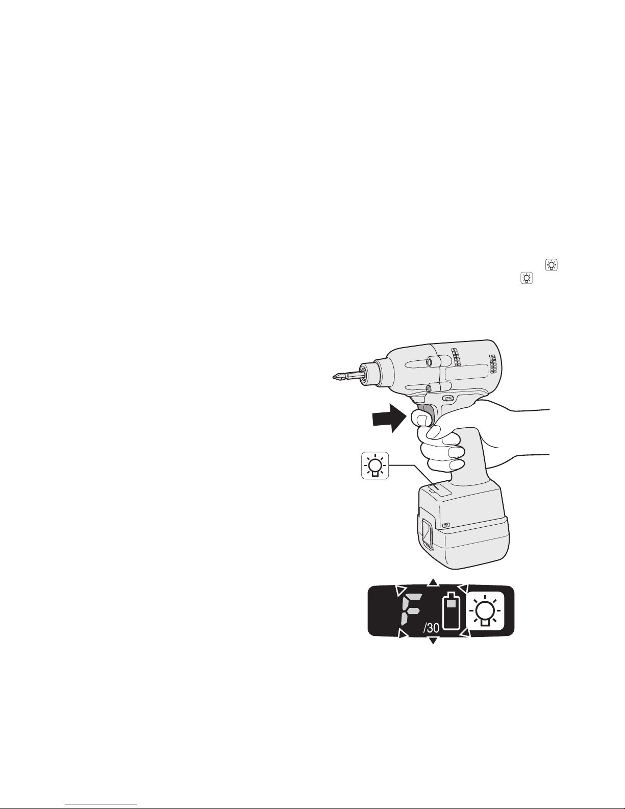
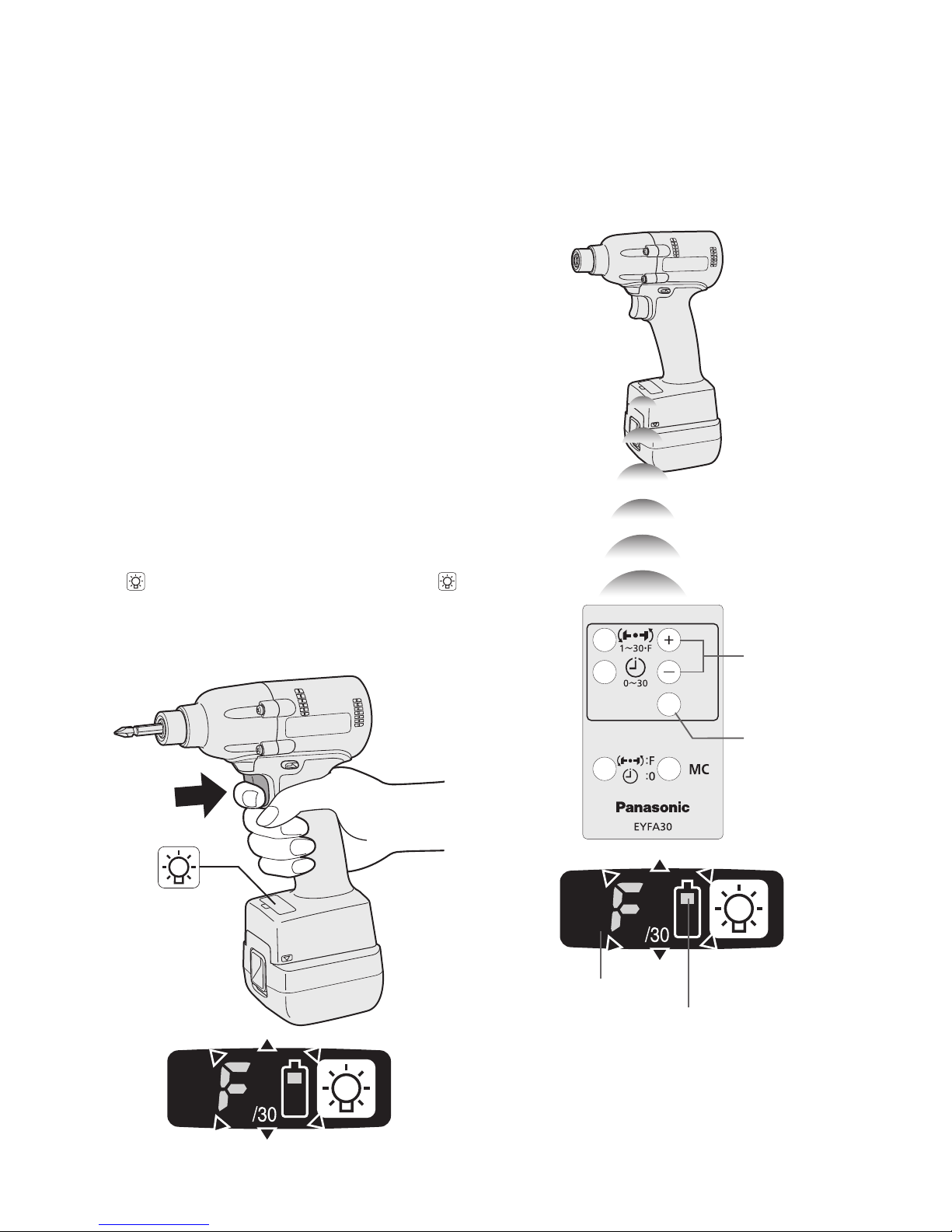
Setting the tool to configuration mode
1. Turn off the control panel.
• If the control panel is on, remove and
then reinsert the battery pack.
2. Engage the switch while pushing the
button and then release both the button and the switch.
• After all the LED lamps have turned off,
the control panel will flash and change
to configuration mode.
NOTE:
• Tools ship from the factory set to “F”
mode (torque control function off).
• The control panel will turn off if the tool
is not operated for a period of 5 minutes.

-
11 -
Configuring the torque clutch setting
(1)
(2)
Display
Battery indication lamp
1. Press the and buttons to select the
clutch setting that is appropriate for the
work being performed.
3…28
1F30 229
As the button
is pressed
As the button
is pressed
• “F” indicates that the torque control function is off.
• You can select from 30 torque clutch
settings (1 to 30).
• Use figures from the Tightening Torque
Chart to guide your selection of torque
clutch setting. (See the following tightening torque chart)
2. Press the OK button to accept the select
-
ed torque clutch setting.
• The control panel will stop flashing and
light up.
CAUTION:
• You must press the OK button in order
for the selected setting to take effect.
• Be sure to verify the new value after
changing the setting.
Setting the snug point detection level
(2)
(3)
(1)
1. Press the torque setting mode button.
• The snug point detection level setting
value will be displayed.
Display
Battery indication lamp
2. Press the and buttons to set the best
snug point detection level for the work
you’re performing.
Display Snug point detection level
L1
Low
(Use for work characterized by
low loads before the snug point
is reached.)
L2
High
(Use for work characterized by
high loads before the snug point
is reached.)
3. Press the OK button to accept the number
of torque stages and the snug point detection level.
• The tool’s panel will flash and then light
up continuously.
-
12 -
CAUTION:
• Set the snug point detection level from
“L1.” Setting the snug point detection level
from “L2” may result in cracking or defor
-
mation of the target material.
• If the tool stops before the snug point at
snug point detection level “L1,” set the
snug point detection level to “L2.”
• Changing the snug point detection level
from “L1” to “L2” may increase the torque.
Set the number of torque stages again
after making this change.
• The setting will not be changed until
you press the OK button.
•
After changing the setting, be sure to check
the new setting value. (See page 13.)
IMPORTANT INFORMATION:
• You can set the snug point detection
level and retightening prevention time at
the same time by changing the retightening prevention time (see page 12)
before pressing the OK button and then
pressing the OK button.
• Pressing the torque setting mode but
ton toggles the display between the
snug point detection level setting value
and the number of torque stages setting value.
• The tool ships with the snug point
detection level set to “L1.”
• When the number of torque stages has
been set as shown below, the snug
point detection level cannot be switched
from “L1” to “L2.”
Model
Number of torque stages
setting
EYFLA4 1 to 8
EYFLA5 1 to 3
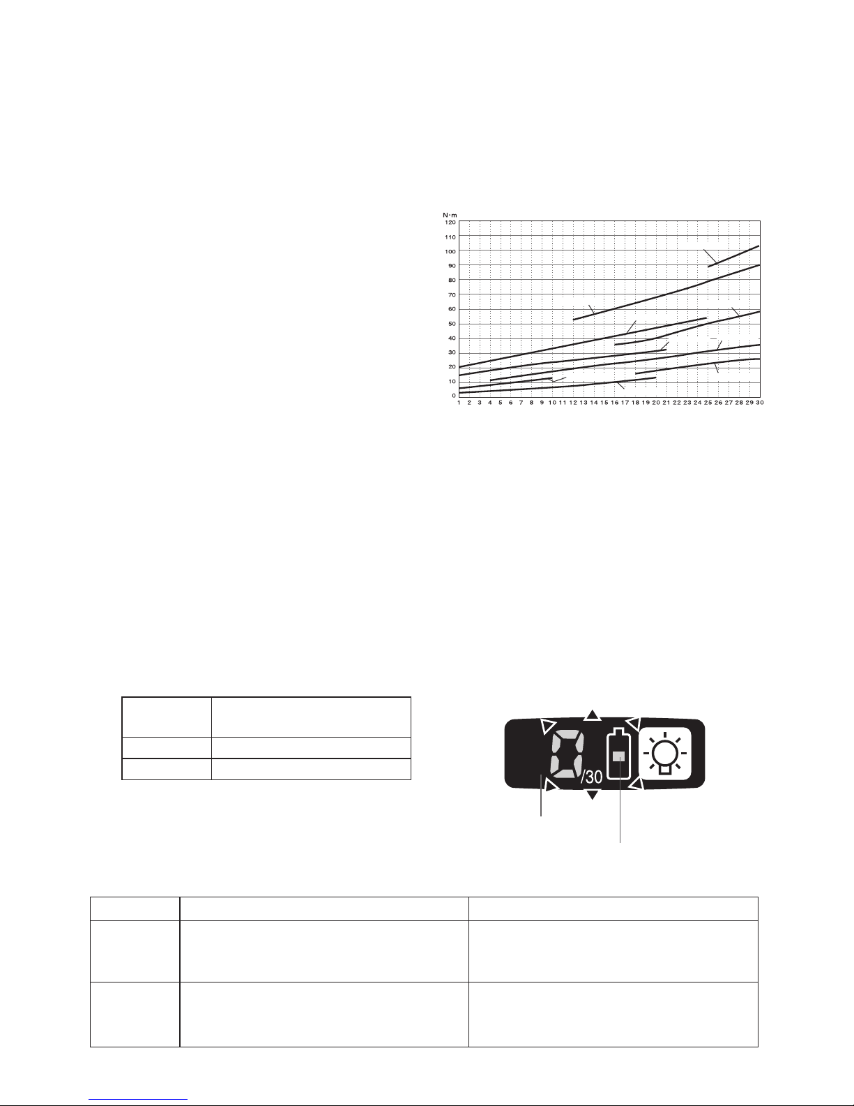
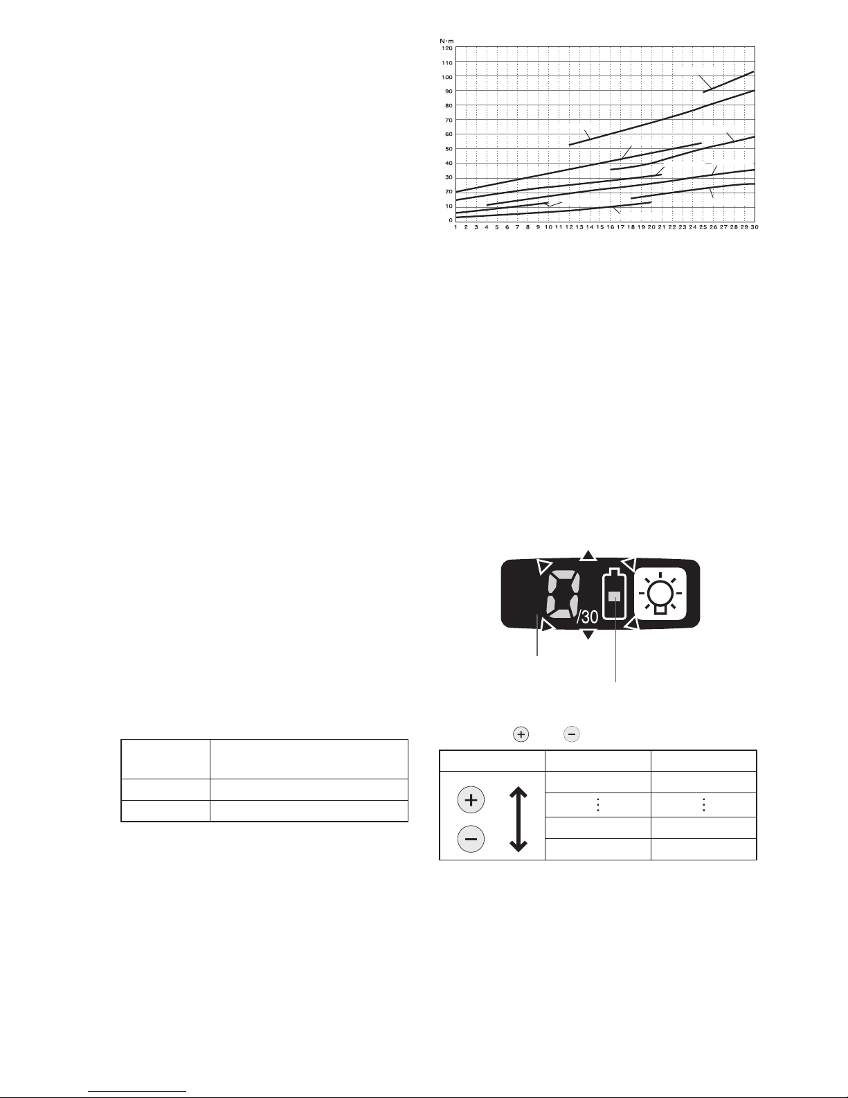
Tightening Torque Chart (for Reference
Use)
The values illustrated on this chart were measured under the conditions described below
and are provided for reference purposes.
Actual tightening torque varies with ambient
conditions (the particular bolt being tightened,
hardware being used, method of holding the
bolt in place, etc.).
EYFLA6(M8)
EYFLA5(M6)
EYFLA4(M6)
EYFLA4(M8)
EYFLA6(M10)
EYFMA1(M10)
EYFMA1(M12)
EYFMA1(M14)
EYFLA5(M8)
Measurement conditions
• Temperature: Room temperature (20°C/68°F)
Using the Interval Set
• The interval set operates to prevent the tool
from operating after it automatically stops as
a result of the torque control function, even if
the switch is engaged.
1. Set the tool to configuration mode.
(See page 10.)
2. Press the interval set button.
• The control panel will begin flashing.
Display: The number 0 ashes on and off.
Battery indication lamp: The middle bar
of the battery ashes on and off.
Display
Battery indication lamp
Snug point detection level guidelines
Display Snug point detection level Applications (reference)
L1
Low
(Use for work characterized by low loads
before the snug point is reached.)
• Tightening bolts in materials that are
easily cracked or deformed, etc.
L2
High
(Use for work characterized by high
loads before the snug point is reached.)
• Tightening bolts in materials with mis
-
aligned holes, etc.
• Tightening self-tapping screws, etc.
-
13 -
3. Press the and buttons to set the
desired time.
Buttons Display Seconds
30 3
1 0.1
0 Off
4. Press the OK button to accept the selected
setting.
• The control panel will stop flashing and
light up, and the torque clutch setting
will be displayed.
CAUTION:
• Be sure to verify the new value after
changing the setting.
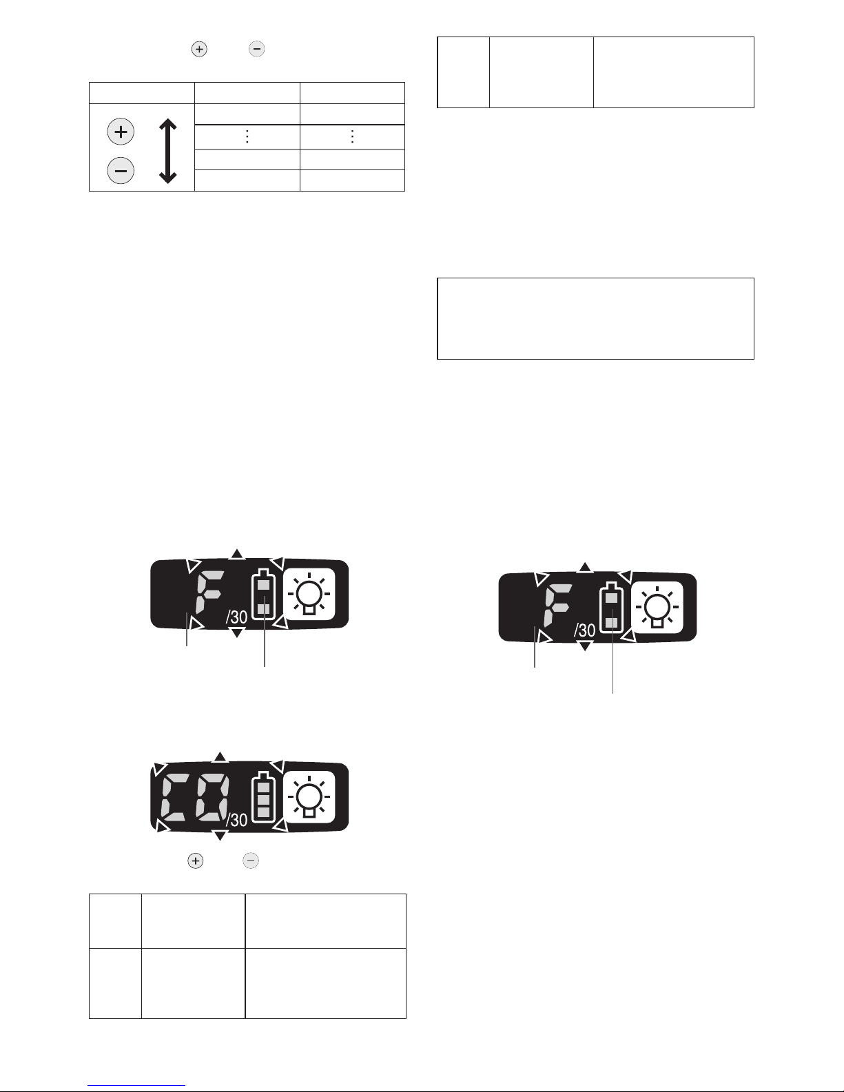
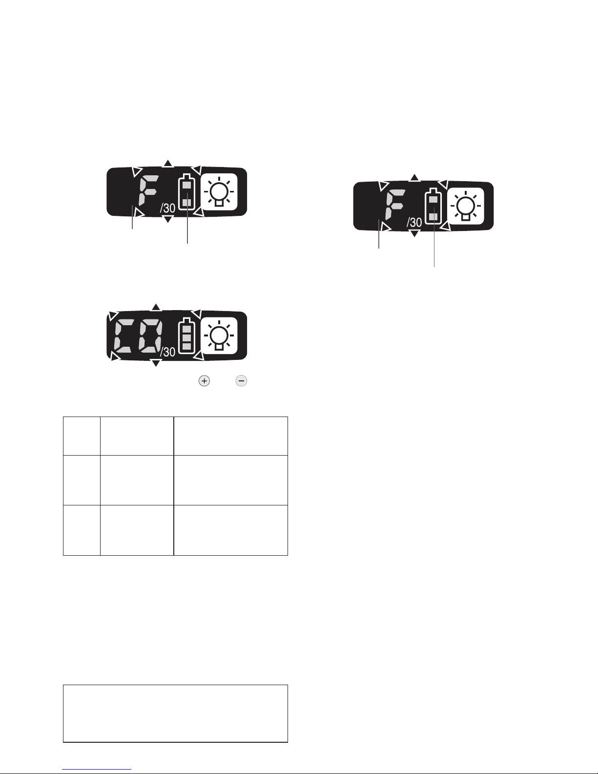
Radio signal range limitation function
on/off setting (EYFLA4AR, EYFLA5AR,
EYFLA5QR, EYFLA6JR, EYFMA1JR)
1. Set the tool to configuration mode.
(See page 10.)
2. Press the format button.
• The control panel will begin flashing.
Display: The letter “F” ashes on and off.
Battery indication lamp: The upper and
lower bars of the battery ash on and off.
Display
Battery indication lamp
3. Press the format button again.
• Radio signal range limitation function
on/off setting value will be displayed.
4. Press the and buttons to set radio
signal range limitation function on/off.
Display
Radio signal
range limitation
function mode
Status
C0 OFF
Tool is operational in the
absence of communications with the Assembly
Qualier.
C1 ON
Tool is not operational
in the absence of communications with the As-
sembly Qualier.
Factory settings
• Radio signal range limitation function
setting: C0 (OFF)
NOTE:
• For more information about how to register
the tool and Assembly Qualifier, see the
Assembly Qualifier instruction manual.
Initializing All Settings
Factory settings
• Torque clutch setting: “F” (torque con
-
trol function off)
• Interval setting: 0 (off)
• This section explains how to revert all tool
settings to their default values at the time of
shipment from the factory.
• The error display will be turned off.
1. Set the tool to configuration mode.
(See page 10.)
2. Press the format button.
• The control panel will begin flashing.
Display: The letter “F” ashes on and off.
Battery indication lamp: The upper and
lower bars of the battery ash on and off.
Display
Battery indication lamp
3. Press the OK button to accept the select-
ed setting.
• The control panel will stop flashing and
light up.
Checking Tool Settings
• This section describes how to have the tool
display current settings for approximately 3
seconds when the tool is stopped.
• You cannot check tool settings when the
control panel is turned off. First, engage
the switch briefly to reactivate the display.
Checking the torque clutch setting
1. Press the torque set button.
• Control panel display
Display: The torque set lights up.
Battery indication lamp: The upper bar of
the battery ashes on and off.
-
14 -
Checking the interval
1. Press the interval set button.
• Control panel display
Display: The interval set lights up.
Battery indication lamp: The middle bar
of the battery ashes on and off.
Checking tool circuits
1. Press the torque level button.
• Control panel display
Display: The torque set display lights up.
Battery indication lamp: The middle and
lower bars of the battery ash on and off.
Display Tool circuit
H6 EYFLA4
H7 EYFLA5
H8 EYFLA6
H9 EYFMA1
NOTE:
• If you engage the switch while a setting
is being displayed, the control panel will
revert to the torque clutch setting display.
CAUTION:
• The torque set display is not intended
to be used to identify the type of drive
component parts (hammer, etc.) used
in a particular tool.
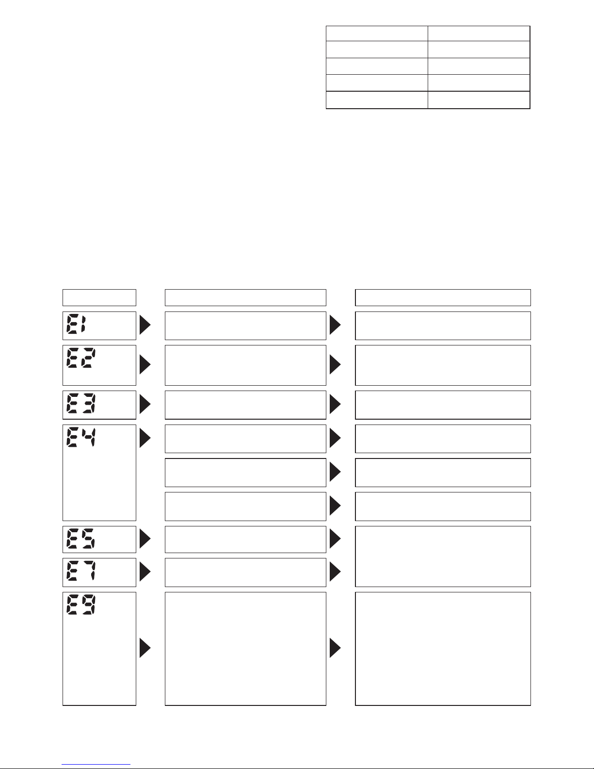
Error Display
In the event of a tool or battery pack malfunction, the control panel will display an error message. Please
check the tool or battery pack as described in the following chart before having them serviced.
Display Likely cause Corrective action
Setting error Re-initialize the tool using the
remote control. (See page 13.)
The battery pack is too hot. Stop work and allow the battery
pack to cool before resuming use
of the tool.
The tool is too hot to operate. Stop work and allow the tool to
cool before resuming use.
The contacts that connect the
battery pack and tool are dirty.
Remove any dirt.
The battery pack has not been
properly inserted into the tool.
Insert the battery pack rmly into
the tool.
The pins on either the tool or
battery pack have worn down.
Replace the battery pack.
Motor failure, etc. Stop using the tool immediately.
Tool circuit malfunction, failure,
etc.
The tool is unable to communicate with the Assembly Quali-
er while the radio signal range
limitation function is on.
• Verify that the tool has been
properly registered to the Assembly Qualifier.
•
Verify that the Assembly Qualifier’s group setting has been configured correctly.
•
Improve the reception state, for
example by moving the Assembly Qualifier closer to the tool.
-
15 -
[Battery Pack]
For Appropriate Use of Bat-
tery Pack
Li-ion Battery Pack
• For optimum battery life, store the Li-ion battery pack following use without charging it.
• When charging the battery pack, confirm
that the terminals on the battery charger
are free of foreign substances such as dust
and water etc. Clean the terminals before
charging the battery pack if any foreign substances are found on the terminals.
The life of the battery pack terminals may be
affected by foreign substances such as dust
and water etc. during operation.
• When battery pack is not in use, keep it
away from other metal objects like: paper
clips, coins, keys, nails, screws, or other
small metal objects that can make a
connection from one terminal to another.
Shorting the battery terminals together may
cause sparks, burns or a fire.
•
When operating the battery pack, make sure
the work place is well ventilated.
•
When the battery pack is removed from the
main body of the tool, replace the battery
pack cover immediately in order to prevent
dust or dirt from contaminating the battery
terminals and causing a short circuit.
Battery Pack Life
The rechargeable batteries have a limited life.
If the operation time becomes extremely short
after recharging, replace the battery pack with
a new one.
Battery Recycling
ATTENTION:
For environmental protection and recycling
of materials, be sure that it is disposed of
at an ofcially assigned location, if there is
one in your country.
[Battery Charger]
Charging
Read the operating manual for Panasonic battery
charger for the battery pack before charging.
Before charging the battery
Charge the battery at a temperature of 5°C
(41°F) to 40°C (104°F).
The battery pack cannot be charged at a temperature of less than 5°C (41°F). If the temperature of the battery pack is less than 5°C
(41°F), rst remove the battery pack from
the charger and allow it to sit for an hour in a
location where the temperature is 5°C (41°F) or
warmer. Then charge the battery pack again.
-
16 -
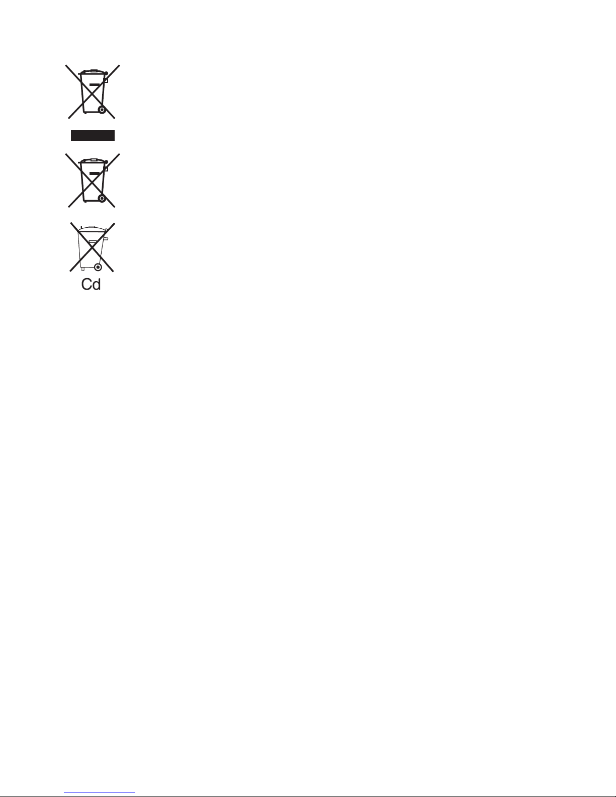
Information for Users on Collection and Disposal of Old Equipment and used Batteries
These symbols on the products, packaging, and/or accompanying documents
mean that used electrical and electronic products and batteries should not be
mixed with general household waste.
For proper treatment, recovery and recycling of old products and used batteries,
please take them to applicable collection points, in accordance with your national
legislation and the Directives 2002/96/EC and 2006/66/EC.
By disposing of these products and batteries correctly, you will help to save valuable
resources and prevent any potential negative effects on human health and the
environment which could otherwise arise from inappropriate waste handling.
For more information about collection and recycling of old products and batteries,
please contact your local municipality, your waste disposal service or the point of
sale where you purchased the items.
Penalties may be applicable for incorrect disposal of this waste, in accordance with
national legislation.
For business users in the European Union
If you wish to discard electrical and electronic equipment, please contact your dealer or
supplier for further information.
[Information on Disposal in other Countries outside the European Union]
These symbols are only valid in the European Union. If you wish to discard these items,
please contact your local authorities or dealer and ask for the correct method of disposal.
Note for the battery symbol (bottom two symbol examples):
This symbol might be used in combination with a chemical symbol. In this case it complies
with the requirement set by the Directive for the chemical involved.
V.
MAINTENANCE
Use only a dry, soft cloth for wiping the unit.
Do not use a damp cloth, thinner, benzine, or
other volatile solvents for cleaning.
VI
. ACCESSORIES
Charger
• EY0L81
Battery pack
• EYFB30
• EYFB40
Remote control
• EYFA30
Protector for tool
• EYFA01-A (Blue)
• EYFA01-Y (Yellow)
• EYFA01-H (Gray)
• EYFA01-G (Green)
Protector for battery
• EYFA02-H
• EYFA04-H
Assembly Qualier
• EYFR02

-
17 -
VII
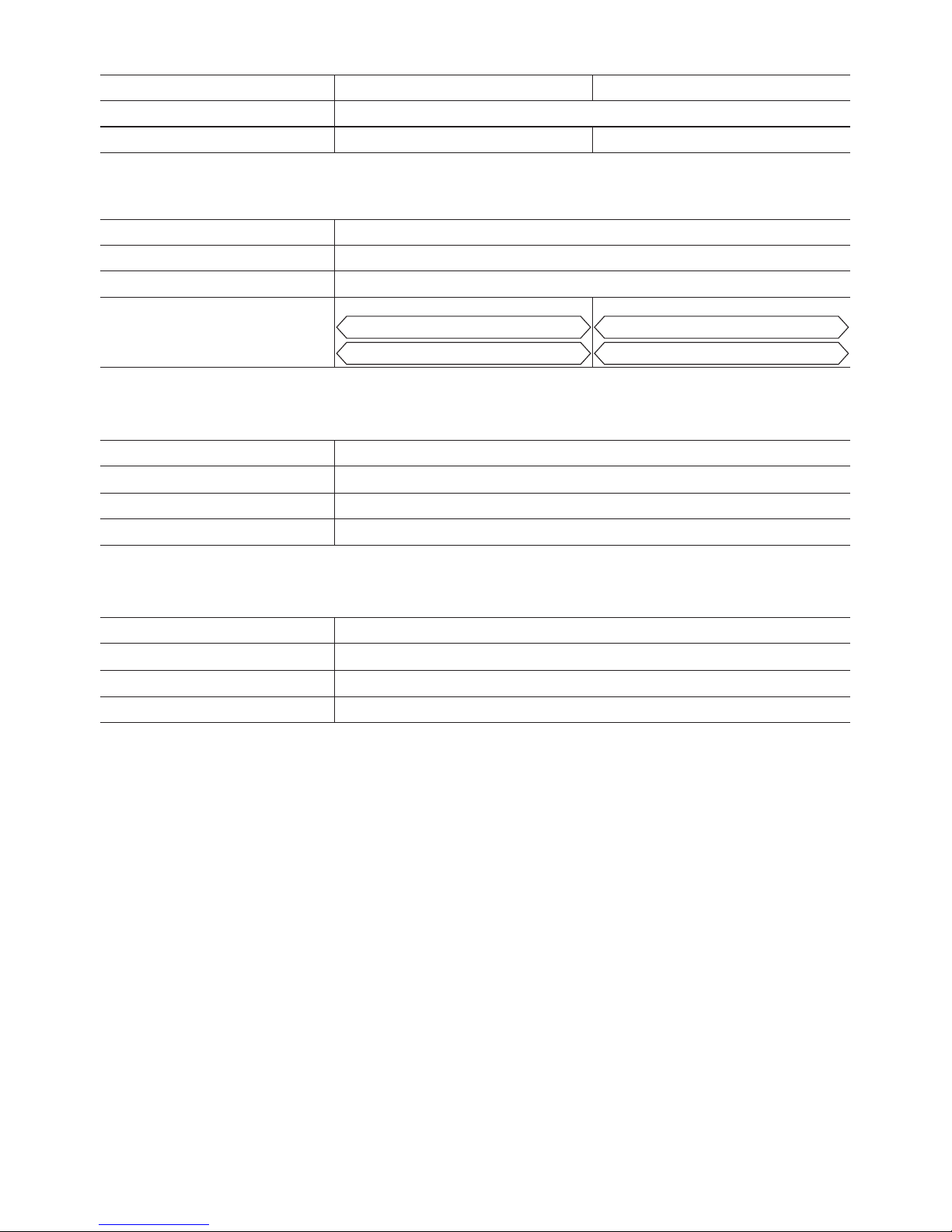
. SPECIFICATIONS
MAIN UNIT
Model EYFLA4 EYFLA5 EYFLA6 EYFMA1
A AR A AR Q• B QR J•B JR J •B JR
Motor 10.8 V DC 14.4 V DC
Chuck
size
Singleended
9 – 9.5 mm
(23/64" – 3/8")
9 – 9.5 mm
(23/64"– 3/8")
□
9.5 mm
(3/8")
□
12.7 mm
(1/2")
□
12.7 mm
(1/2")
Doubleended
12 mm
(15/32")
12 mm
(15/32")
No load
speed
Stage 1
2
3
4 – 8
9 – 30·F
0 – 950
0 – 1300
0 – 1450
0 – 1550
0 – 2300
1
2
3
4 – 30·F
0 – 1300
0 – 1450
0 – 1550
0 – 2300
0 – 2300 0 – 2300
Impact
per
minute
Stage 1
2
3
4 – 8
9 – 30·F
0 – 1900
0 – 2500
0 – 2800
0 – 3000
0 – 4000
1
2
3
4 – 30·F
0 – 2500
0 – 2800
0 – 3000
0 – 3600
0 – 3000 0 – 3200
Maximum torque 40 N·m
(408 kgf-cm,
354 in-lbs)
90 N·m
(918 kgf-cm,
796 in-lbs)
120 N·m
(1224 kgf-cm,
1062 in-lbs)
185 N·m
(1887 kgf-cm,
1637 in-lbs)
Torque control
function operating
range
Approx. 3 – 22 N·m
(31 – 224 kgf-cm,
27 – 195 in-lbs)
Approx. 6 – 30 N·m
(61 – 306 kgf-cm,
53 – 266 in-lbs)
Approx.
16 – 53 N·m
(163 – 540 kgf-cm,
142 – 469 in-lbs)
Approx.
25 – 100 N·m
(255 – 1020 kgf-cm,
310 – 885 in-lbs)
Overall length 158 mm
(6-7/32")
158 mm
(6-7/32")
164 mm
(6-7/16")
172 mm
(6-25/32")
172 mm
(6-25/32")
Weight (with battery
pack: EYFB30)
1.3 kg
(2.8 lbs)
1.3 kg
(2.8 lbs)
1.35 kg
(2.9 lbs)
1.3 kg
(2.8 lbs)
1.35 kg
(2.9 lbs)
1.4 kg
(3.1 lbs)
————
Weight (with battery
pack: EYFB40)
—————————
1.5 kg
(3.3 lbs)
Radio Information:
Indoor/Urban Range 100 ft./30 m
Transmit Power 1 mW (0 dBm)
Receiver Sensitivity -92 dBm (1% packet error)
Channel Frequencies:
Channel 1 2.410 GHz
Channel 2 2.415 GHz
Channel 3 2.420 GHz
Channel 4 2.425 GHz
Channel 5 2.430 GHz
Channel 6 2.435 GHz
Channel 7 2.440 GHz
Channel 8 2.445 GHz
Channel 9 2.450 GHz
Channel 10 2.455 GHz
Channel 11 2.460 GHz
Channel 12 2.465 GHz
-
18 -
BATTERY PACK (not included with shipment)
Model EYFB30 EYFB40
Storage battery Li-ion battery
Battery voltage 10.8 V DC (3.6 V/6 cells) 14.4 V DC (3.6 V/8 cells)
BATTERY CHARGER (not included with shipment)
Model EY0L81
Rating See the rating plate on the bottom of the charger.
Weight 0.93 kg (2.0 lbs)
Charging time
EYFB30
Usable: 40 min.
Full: 65 min.
EYFB40
Usable: 50 min.
Full: 65 min.
Remote control (not included with shipment)
Model EYFA30
Battery voltage 3 V DC
Dimensions 54 mm (2-1/8") × 86 mm (3-3/8") × 10 mm (13/32”)
Weight (with battery) Approximately 29 g (0.6 lbs)
Assembly Qualifier (not included with shipment)
Model EYFR02
Rating See the rating plate on the bottom of the Assembly Qualier.
Dimensions 120 mm (4-3/4") × 260 mm (10-1/4") × 70 mm (2-3/4")
Weight (with battery) 1.1 kg (2.4 lbs)
-
19 -
ONLY FOR U. K.
VIII
.
ELECTRICAL PLUG
INFORMATION
FOR YOUR SAFETY PLEASE READ
THE FOLLOWING TEXT CAREFULLY
This appliance is supplied with a moulded
three pin mains plug for your safety and
convenience.
A 5 amp fuse is tted in this plug.
Should the fuse need to be replaced please
ensure that the replacement fuse has a rating of 5 amp and that it is approved by ASTA
or BSI to BS1362.
Check for the ASTA mark or the BSI mark
on the body of the fuse.
If the plug contains a removable fuse cover
you must ensure that it is retted when the
fuse is replaced.
If you lose the fuse cover the plug must not
be used until a replacement cover is obtained.
A replacement fuse cover can be purchased
from your local Panasonic Dealer.
IF THE FITTED MOULDED PLUG IS UNSUITABLE FOR THE SOCKET OUTLET IN
YOUR HOME THEN THE FUSE SHOULD
BE REMOVED AND THE PLUG CUT OFF
AND DISPOSED OF SAFELY.
THERE IS A DANGER OF SEVERE ELECTRICAL SHOCK IF THE CUT OFF PLUG
IS INSERTED INTO ANY 13 AMP SOCKET.
If a new plug is to be tted please observe
the wiring code as shown below.
If in any doubt please consult a qualied
electrician.
IMPORTANT:
The wires in this mains lead are coloured in accordance with the following
code:
Blue: Neutral
Brown: Live
As the colours of the wire in the mains lead
of this appliance may not correspond with
the coloured markings identifying the terminals in your plug, proceed as follows.
The wire which is coloured BLUE must be
connected to the terminal in the plug which
is marked with the letter N or coloured
BLACK.
The wire which is coloured BROWN must be
connected to the terminal in the plug which is
marked with the letter L or coloured RED.
Under no circumstances should either of
these wires be connected to the earth terminal of the three pin plug, marked with the
letter E or the Earth Symbol .
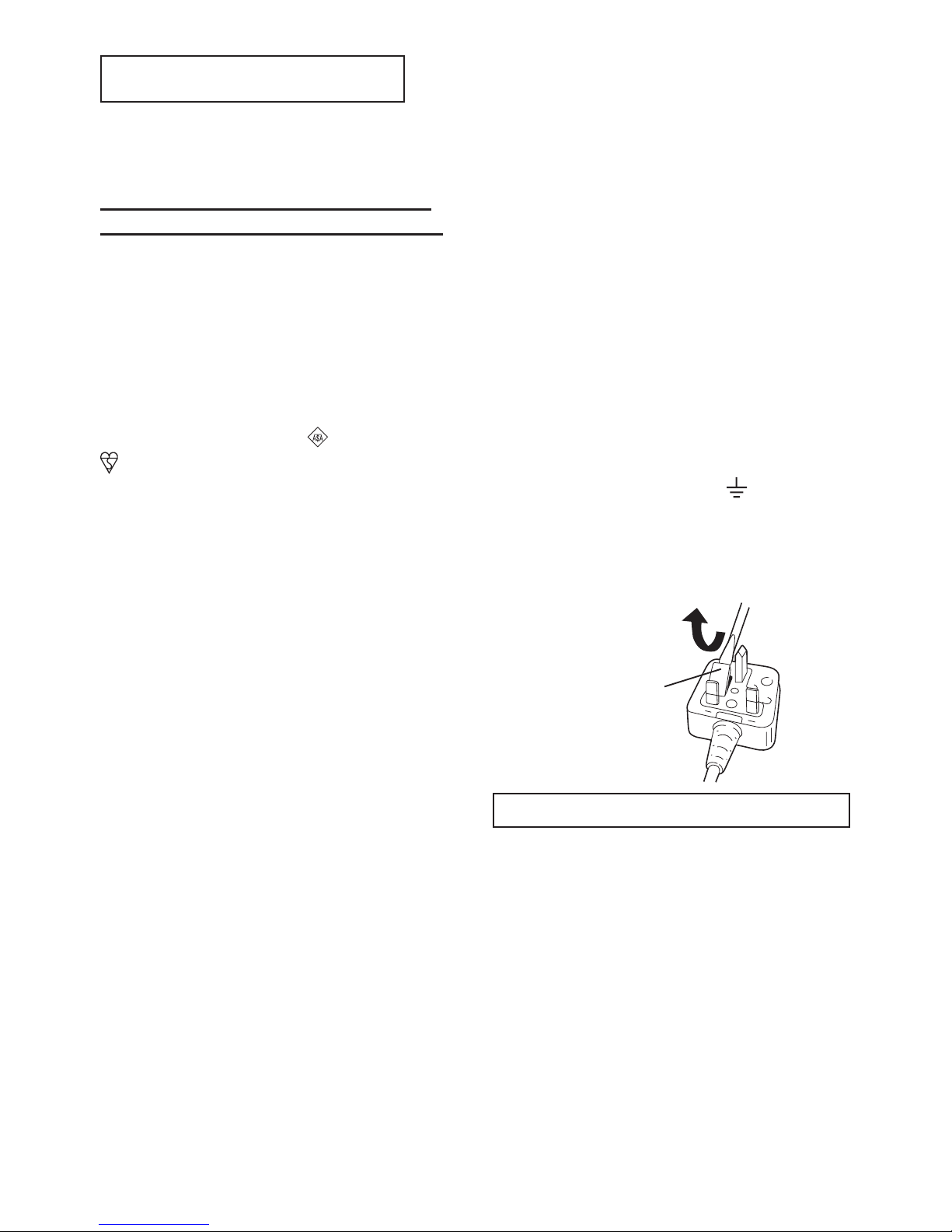
How to replace the fuse: Open the fuse
compartment with a screwdriver and replace
the fuse and fuse cover if it is removable.
Fuse Cover
This apparatus was produced to BS800.

-
20 -
Original-Anleitung: Englisch
Übersetzung der Original-Anleitung:
Andere Sprachen
I
. VERWENDUNGS-
ZWECK
Dieses Werkzeug ist ein Akku-Schlagschrauber
und kann zum Anziehen von Bolzen, Muttern
und Schrauben verwendet werden. Darüber
hinaus bietet es eine Anzugsmoment-Steuerfunktion, die den Werkzeugbetrieb automatisch
stoppt, wenn eine voreingestellte Last erreicht
wird, um ein gleichmäßiges Anzugsmoment
zu liefern.
FALSCHER GEBRAUCH
ZWECKENTFREMDETER GEBRAUCH des
Werkzeugs ist gefährlich und muss vermieden
werden.
Das Werkzeug darf nicht für folgende Zwecke
verwendet werden:
• Mischen von Lackfarben oder Baumaterial,
• Polieren, Schleifen, Schärfen, Gravieren.
RESTRISIKO
Einige Restrisiken wie die folgenden bleiben selbst bei sachgemäßem Gebrauch des
Werkzeugs bestehen:
• Kontakt mit dem rotierenden Einsatz
• Kontakt mit scharfen Kanten des Materials
oder dergleichen.
Lesen Sie bitte vor der ersten Inbetriebnahme dieses Gerätes das separate Handbuch
„Sicherheitsmaßregeln“ sorgfältig durch.
II
.
WEITERE WICHTIGE
SICHERHEITSREGELN
1) Geeigneten Gehörschutz tragen, wenn
das Werkzeug längere Zeit im Betrieb ist!
2) Denken Sie daran, dass das Werkzeug
ständig betriebsbereit ist, da es nicht an
die Steckdose angeschlossen werden
muss.
3) Beim Schrauben in Wände, Fußböden
usw. kön nen s tr om fü hr en de Kabel
berührt werden. DAHER NIE DAS VIERKANTSCHNELLSPANNFUTTER ODER
AND ERE VORDERE M ETA LLT EILE
BE RÜH REN ! Das Wer kz e ug b eim
Schrauben nur am Kunststoffgriff halten,
um in solchen Fällen vor elektrischen
Schlägen geschützt zu sein.
4) Betätigen Sie den Rechts-/LinkslaufUmschalthebel NICHT, wenn der Hauptschalter eingeschaltet ist. Der Akku entlädt
sich sonst schnell, und das Gerät kann
beschädigt werden.
5) Beim Aufladen kann sich das Ladegerät
etwas erhitzen. Dies ist normal.
Den Akku daher NICHT über lange Zeit
aufladen.
6) Stellen Sie den Rechts-/Linkslauf- Umschal
thebel zum Lagern oder Tragen des
Werkzeugs auf die Mittenstellung (Schaltersperre).
7) Belasten Sie das Werkzeug nicht, indem
Sie den Elektronikschalter halb gedrückt
halten (Drehzahlregelmodus), sodass der
Motor stehen bleibt.
Symbol
Bedeutung
V
Volt
Gleichstrom
n
0
Leerlaufdrehzahl
… min
-1
Drehzahl oder Hubzahl pro
Minute
Ah
Akkukapazitat in Ampere
Stunden
III
. BAUGRUPPE
Anbringen oder Abnehmen
des Bits
HINWEIS:
• Trennen Sie vor dem Anbringen oder Abneh-
men eines Bits den Akku vom Werkzeug
ab, oder stellen Sie den Elektronikschalter
auf die Mittelstellung (Schaltersperre).
1. Die Hülse des Schnellspannfutters halten
und vom Werkzeug herausziehen.
2. Den Bit in das Bohrfutter einsetzen. Die
Hülse loslassen.
3. Der Ring springt in seine Ausgangsposition
zurück, wenn er losgelassen wird.

-
21 -
4.
An dem Bit ziehen, um sicherzustellen, das er
nicht abgezogen werden kann.
5. Zum Entfernen des Bits die Hülse auf die
gleiche Weise herausziehen.
VORSICHT:
• Wenn der Ring nicht in seine Ausgangs-
position zurückkehrt oder wenn sich
der Bit löst, wenn an ihm gezogen wird,
wurde der Bit nicht ordnungsgemäß eingesetzt. Vor der Inbetriebnahme sicherstellen, dass der Bit ordnungsgemäß befestigt ist.
EYFLA4A/EYFLA4AR/EYFLA5A/EYFLA5AR
12 mm
(15/32")
9 mm – 9,5 mm
(23/64" – 3/8")
6,35 mm
(1/4")
Anbringen einer Stecknuss
(Stifttyp)
• Den Gummiring und Stift der Stecknuss ent-
fernen.
Gummiring
Stift
Nut
1 Die Stecknuss am Werkzeug anbringen.
2 Den Stift einsetzen. (Die Stiftlöcher in Steck-
nuss und Werkzeug sorgfältig ausrichten.)
3 Den Gummiring durch Aufschieben auf die
Nut anbringen.
HINWEIS:
Bringen Sie unbedingt den Gummiring an,
um Herausfallen des Stifts zu verhüten.
Abnehmen einer Stecknuss
(Stifttyp)
1 Den Gummiring entfernen.
2 Den Stift entfernen.
3 Die Stecknuss vom Werkzeug abnehmen.
Anbringen oder Abnehmen einer
Stecknuss (Kugelrastentyp)
1. Anbringen einer Stecknuss
Bringen Sie die Stecknuss an, indem Sie die
Fassung an der Unterseite der Stecknuss
auf den Vierkant am Werkzeug schieben.
Vergewissern
Sie sich, dass
die Stecknuss
fest mit dem
Werkzeug verbunden ist.
2. Abnehmen einer Stecknuss
Ziehen Sie die Stecknuss ab.
Anbringen oder Abnehmen
des Akkus
1. Zum Anschließen des Akkus:
Die Ausrichtmarkierungen aufeinander
ausrichten, und den Akku anbringen.
• Den Akku einschieben, bis er einrastet.
Ausrichtmarkierungen
2. Zum Entfernen des Akkus:
Zum Abnehmen des Akkus den Knopf an
der Vorderseite hochdrücken.
Knopf

-
22 -
IV
. BETRIEB
Vor Benutzung der Fernbedienung (Als Sonderzubehör erhältlich)
Die Batterie einlegen
1. Den Batteriehalter
herausziehen.
1 Die Raste in Pfeilrich-
tung hineindrücken.
2 Den Halter heraus-
ziehen.
2. Die Batterie ein
legen, und den
Halter wieder einschieben.
HINWEIS:
• Falls das Werkzeug nicht auf die draht
lose Fernbedienung reagiert, selbst wenn
die Fernbedienung nahe am Werkzeug
betätigt wird, ist die Batterie (CR2025)
erschöpft. Ersetzen Sie die Batterie durch
eine neue.
• Die mitgelieferte Batterie ist für Probe
betrieb vorgesehen und hält möglicherweise nicht so lange wie eine im Handel
erhältliche Batterie.
Reichweite der drahtlosen Fernbedienung
ca. 50 cm
Vertikal
c
a
.
6
0
°
c
a
.
6
0
°
Die Fernbedienung sollte innerhalb von etwa
50 cm und 60° vertikal und horizontal zur Senkrechten relativ zum Infrarotempfänger des
Werkzeugs betätigt werden.
• Unter den folgenden Umständen lässt sich
das Werkzeug selbst innerhalb dieses
Bereichs eventuell nicht bedienen.
• Wenn sich ein Gegenstand zwischen dem
Geber der Fernbedienung und dem Empfänger des Werkzeugs befindet.
• Bei Verwendung im Freien oder in anderen
Umgebungen, wo der Fernbedienungsempfänger einer starken Lichtquelle ausgesetzt
ist, oder wenn der Fernbedienungsgeber
oder -empfänger schmutzig ist, reagiert das
Werkzeug eventuell nicht, selbst wenn die
Fernbedienung innerhalb des Wirkungsbereichs benutzt wird.
[Hauptteil]
Umschalten und Betätigung
des Rechts-/Linkslauf- Umschalthebels
Rechts Links
Schaltersperre
VORSICHT:
Nicht den Rechts-/Linkslauf- Umschalthebels betätigen, bevor der Bit vollständig
zur Ruhe gekommen ist, um Schäden zu
verhindern.
Rechtslauf - Schalterbetätigung
1. Für Rechtslauf den Hebel drücken.
2. Drücken Sie den Schalter leicht, um das
Werkzeug langsam zu starten.
3. Die Drehzahl nimmt zu, je stärker der Aus
löser gedrückt wird, um effizientes Anziehen von Schrauben zu ermöglichen. Beim
Loslassen des Auslösers wird die Bremse
betätigt und der Bit sofort angehalten.
4. Nach der Verwendung den Hebel auf die
Mittenposition zurückstellen (Schaltersperre).
-
23 -
Linkslauf - Schalterbetätigung
1.
Für Linkslauf den Hebel drücken. Die Drehrichtung vor dem Betrieb prüfen.
2.
Drücken Sie den Schalter leicht, um das
Werkzeug langsam zu starten.
3. Nach der Verwendung den Hebel auf die
Mittenposition zurückstellen (Schaltersperre).
VORSICHT:
• Um übermäßigen Temperaturanstieg der
Werkzeugoberfläche zu vermeiden, sollte
das Werkzeug nicht kontinuierlich mit
zwei oder mehr Akkus betrieben werden.
Das Werkzeug muss vor dem Anschluss
eines anderen Akkus abkühlen.
Anzugsbestätigungslampe
• Anhand der Anzugsbestätigungslampe kann
festgestellt werden, ob die AnzugsmomentSteuerfunktion aktiviert wurde.
Werkzeugstatus Lampenanzeige
Anziehen beendet
(bei wirksamer
AnzugsmomentSteuerfunktion)
Grün
(Für ca. 2
Sekunden)
• Anziehen unvollständig
• Anziehen beendet mit
Nachziehen innerhalb 1
Sekunde
Rot
(Für ca. 2
Sekunden)
Die automatische
Stoppfunktion ist aktiviert
worden.
Rot
(Für ca. 5
Minuten)
VORSICHT:
• Wenn das Werkzeug automatisch anhält,
nachdem der Schalter während des
Anziehens im Schlagmodus losgelassen
wurde und dann innerhalb 1 Sekunde
wieder betätigt wird, leuchtet die rote
Lampe auf, um auf die Gefahr eines
übermäßigen Anzugsmoments durch
Nachziehen hinzuweisen.
HINWEIS:
• Unter den folgenden Bedingungen
leuchtet die Anzugsbestätigungslampe
nicht auf:
• Wenn die Drehmomentkupplung auf „F“
gesetzt wird
• Während des Linkslaufbetriebs
• Die Lampe erlischt, wenn das Werkzeug
in Betrieb ist.
Bedienfeld
(1) (2) (3)
(1) LED-Leuchte
Durch Drücken von wird die LED-Leuchte
ein- und ausgeschaltet.
Die Leuchte verbraucht nur sehr wenig Strom
und beeinträchtigt weder die Leistung des
Werkzeugs während des Betriebs noch die
Akkukapazität.
VORSICHT:
•
Die eingebaute LED-Leuchte ist für
kurzzeitige Beleuchtung eines kleinen
Arbeitsbereichs ausgelegt.
•
Verwenden Sie sie nicht als Ersatz für
eine normale Taschenlampe, weil sie
nicht hell genug ist.
Vorsicht: SEHEN SIE NICHT IN DEN
STRAHL.
Die Verwendung von Bedienelementen, Einstellungen oder Vorgängen außer den hier beschriebenen kann zur Freisetzung gefährlicher
Strahlung führen.
(2) Akku-Anzeigelampe
• Anhand der Akku-Anzeigelampe können Sie
den Ladezustand des Akkus feststellen.
• Die Nutzungsdauer des Akkus unterliegt je
nach der Umgebungstemperatur und den
Akku-Eigenschaften geringen Schwankungen. Die Lampe dient dazu, eine ungefähre
Anzeige der Restnutzungsdauer des Akkus
zu liefern.
-
24 -
Akku-Anzeigelampe
Anzeige Akkustatus
Voll aufgeladen
ca. 40% oder weniger
Restladung
Blinken
Blinken
ca. 20 % oder weniger
Restladung (Akku muss
aufgeladen werden)
Der Akku muss bald aufgeladen werden.
Blinken
Keine Ladung
Der Akku muss aufgeladen
werden.
(In diesem Stadium wird
die Abschaltautomatik des
Werkzeugs aktiviert.)
Abschaltautomatik
• Die Abschaltautomatik dient dazu, ein mangelhaftes Anzugsmoment durch reduzierte Akkuspannung zu verhüten. Wenn die
Funktion einmal aktiviert worden ist, lässt
sich das Werkzeug nicht benutzen, bis der
Akku aufgeladen (oder durch einen frischen
ersetzt) worden ist, selbst wenn der Auslöser
gedrückt wird.
Akku-Anzeigelampe
Anzeige
Blinken
HINWEIS:
• Alle 3 Balken der Akku-Anzeigelampe
blinken, wenn die Abschaltautomatik
aktiviert wird.
• Wenn die Akku-Anzeigelampe zu blinken
beginnt, sollte der Akku unverzüglich
aufgeladen (oder durch einen frischen
ersetzt) werden.
• Laden Sie den betreffenden Akku nach
der Aktivierung der Abschaltautomatik
voll auf. Anderenfalls wird die Abschaltautomatik eventuell nicht korrekt deaktiviert.
(3) Anzugsmoment-Steuerfunktion
• Die Anzugsmoment-Steuerfunktion berechnet
die Last anhand des Motordrehwinkels
während des Hammerschlags und stellt
fest, dass die Schraube einwandfrei aufsitzt, wenn ein voreingestellter Lastwert
überschritten wird. Der Anziehvorgang wird
dann automatisch gestoppt, nachdem eine
voreingestellte Anzahl von Schlägen auf die
Schraube ausgeübt worden ist.
VORSICHT:
•
Überprüfen Sie stets das Anzugsmoment
des Werkzeugs vor Gebrauch. Die erforderliche Einstellung hängt von der Art der
Gewindeverbindung ab und kann am besten
durch praktische Versuche ermittelt werden.
Überprüfen Sie die Probeverschraubungen
mit einem Drehmomentschlüssel. Falscher
Werkzeugbetrieb kann zu übermäßigem
oder unangemessenem Anziehen führen.
• Betreiben Sie das Werkzeug stets mit
voll eingerücktem Schalter. Die Anzugsmoment-Steuerfunktion ist unwirksam,
wenn der Schalter nicht richtig eingerastet
ist, so dass automatisches Stoppen des
Werkzeugs verhindert wird.
• Wenn Arbeiten ausgeführt werden, bei
denen während des Anziehens eine
große Kraft ausgeübt wird, kann die
Kraft als Aufsitzen der Schraube interpretiert werden, wodurch vollständiges
Anziehen der Schraube verhindert wird.
• Durch wiederholtes Anziehen derselben
Schraube kann infolge übermäßigen
Anziehens die Schraube beschädigt
oder das Material, in das die Schraube
eingedreht wird, verformt werden.
• Der A nzugs momen twert und die
Genauigkeit hängen von solchen
Faktoren wie dem Material, in das die
Schraube eingedreht wird, und dem
Zustand der verwendeten Stecknuss ab.
Passen Sie das Anzugsmoment je nach
Bedarf an die durchgeführte Arbeit an.
Das Schrauben-Anzugsmoment hängt
von den unten beschriebenen Faktoren
ab.
-
25 -
1) Schraube
• Schraubendurchmesser: Das Anzugsmoment nimmt im Allgemeinen mit dem
Schraubendurchmesser zu.
• Drehmomentkoeffizient (vom Schraubenhersteller angegeben), Grad, Länge
usw.
2) Sonstiges
• Zustand von Einsatz und Stecknuss:
Material, Spielbetrag usw.
• Verwendung eines Kreuzgelenks oder
Steckschlüsseladapters
• Benutzer: Art und Weise des Ansetzens
des Werkzeugs an die Schraube, Kraft,
mit der das Werkzeug gehalten wird,
Art und Weise der Betätigung des Werkzeugschalters
• Zustand des zu verschraubenden
Objekts: Material, Verarbeitung der
Sitzfläche
Einstellen des Werkzeugs auf den Konfigurationsmodus
1. Das Bedienfeld ausschalten.
• Falls das Bedienfeld eingeschaltet ist, den
Akku entnehmen und wieder einsetzen.
2. Den Schalter einrücken, während die Taste
gedrückt wird, und dann die Taste
und den Schalter loslassen.
• Nachdem alle LED-Lampen erloschen
sind, blinkt das Bedienfeld und wechselt
zum Konfigurationsmodus.
HINWEIS:
• Das Werkzeug wurde werksseitig auf
den Modus „F“ (Anzugsmoment-Steuerfunktion abgeschaltet) eingestellt.
• Das Bedienfeld schaltet sich aus, wenn
das Werkzeug für die Dauer von 5
Minuten nicht benutzt wird.
Konfigurieren der DrehmomentkupplungsEinstellung
(1)
(2)
Anzeige
Akku-Anzeigelampe
-
26 -
1. Wählen Sie durch Drücken der Tasten
und die für die durchzuführende Arbeit
geeignete Kupplungseinstellung.
3…28
1F30 229
Drücken der
Taste
Drücken der
Taste
• „F“ zeigt an, dass die AnzugsmomentSteuerfunktion abgeschaltet ist.
• 30 Einstellungen der Drehmomentkupplung (1 bis 30) stehen zur Auswahl.
• Treffen Sie Ihre Wahl der Drehmomentkupplungs-Einstellung anhand der Werte
im Anzugsmomentdiagramm. (Siehe
das nachstehende Anzugsmomentdiagramm)
2. Drücken Sie die Taste OK, um die gewählte
Drehmomentkupplungs-Einstellung zu
akzeptieren.
• Das Bedienfeld hört auf zu blinken und
leuchtet auf.
VORSICHT:
• Sie müssen die Taste OK drücken,
damit die gewählte Einstellung wirksam
wird.
• Bestätigen Sie den neuen Wert nach
einer Änderung der Einstellung.
Einstellen des Aufsitzpunkt-Erkennungsniveaus
(2)
(3)
(1)
1. Drücken Sie die Drehmoment-Einstellmodustaste.
• Der Einstellwert des AufsitzpunktErkennungsniveaus wird angezeigt.
Anzeige
Akku-Anzeigelampe
2. Drücken Sie die Tasten und , um das
optimale Aufsitzpunkt-Erkennungsniveau
für die durchzuführende Arbeit einzustellen.
Anzeige Aufsitzpunkt-Erkennungsniveau
L1
Niedrig
(Für Arbeiten verwenden, die
durch niedrige Lasten chara-
kterisiert werden, bevor der
Aufsitzpunkt erreicht wird.)
L2
Hoch
(Für Arbeiten verwenden, die
durch hohe Lasten charak-
terisiert werden, bevor der
Aufsitzpunkt erreicht wird.)
3. Drücken Sie die Taste OK, um die Zahl der
Drehmomentstufen und das AufsitzpunktErkennungsniveau zu akzeptieren.
• Das Bedienfeld des Werkzeugs blinkt
und leuchtet dann ständig.
VORSICHT:
•
Stell e n S i e d a s A u f s itzpunkt Erkennungsniveau ab „L1“ ein. Wird das
Aufsitzpunkt-Erkennungsniveau ab „L2“
eingestellt, kann es zu Rissbildung oder
Verformung des Zielmaterials kommen.
Richtlinien für Aufsitzpunkt-Erkennungsniveau
Anzeige Aufsitzpunkt-Erkennungsniveau Anwendungen (Referenz)
L1
Niedrig
(Für Arbeiten verwenden, die durch
niedrige Lasten charakterisiert werden,
bevor der Aufsitzpunkt erreicht wird.)
• Anziehen von Schrauben in Material,
das anfällig für Rissbildung oder
Verformung usw. ist.
L2
Hoch
(Für Arbeiten verwenden, die durch
hohe Lasten charakterisiert werden,
bevor der Aufsitzpunkt erreicht wird.)
• Anziehen von Schrauben in Material
mit falsch ausgerichteten Löchern usw.
• Anziehen von Schneidschrauben usw.
-
27 -
•
Falls das Werkzeug bei Einstellung auf
das Aufsitzpunkt-Erkennungsniveau
„L1“ vor dem Aufsitzpunkt stehen
bleibt, stellen Sie das AufsitzpunktErkennungsniveau auf „L2“ ein.
• Dur c h Än der n de s Aufs i tzp u n ktErkennungsniveaus von „L1“ auf „L2“
kann sich das Drehmoment erhöhen.
Stellen Sie die Drehmomentstufenzahl
nach dieser Änderung erneut ein.
• Die Einstellung wird erst durch Drücken
der Taste OK geändert.
•
Überprüfen Sie unbedingt den neuen
Einstellwert, nachdem Sie die Einstellung
geändert haben. (Siehe Seite 28.)
WICHTIGE INFORMATION:
• S i e k ö n n e n das A u f s i t z p u n k t E r k e n n u n g s n i v e a u u n d d i e
N a c h z i e h v e r h ü t u n g s z e i t gl e i chzeitig einstellen, indem Sie die
Nachziehverhütungszeit ändern (siehe
Seite 27), bevor Sie die Taste OK
drücken.
• Durch Drücken der DrehmomentEinstellmodustaste wird die Anzeige
z w i s c h e n d e m A u f s i t z p u n kt Erke nn un gs ni veauwert un d d em
Einstellwert der Drehmomentstufenzahl
umgeschaltet.
• Das Aufsitzpunkt-Erkennungsniveau
des Werkzeugs wird werksseitig auf
„L1“ eingestellt.
• Wenn die Drehmomentstufe nzahl
eingestellt worden ist, wie unten
angegeben, kann das AufsitzpunktErkennungsniveau nicht von „L1“ auf
„L2“ umgeschaltet werden.
Modell
Einstellung der
Drehmomentstufenzahl
EYFLA4 1 bis 8
EYFLA5 1 bis 3
Anzugsmomentdiagramm (nur für Referenzzwecke)
Die in diesem Diagramm angegebenen Werte
wurden unter den nachfolgend beschriebenen
Bedingungen gemessen und dienen Referenzzwecken. Das tatsächliche Anzugsmoment
schwankt je nach den Umgebungsbedingungen (anzuziehende Schraube, verwendete
Hardware, Haltemethode der Schraube usw.).
EYFLA6(M8)
EYFLA5(M6)
EYFLA4(M6)
EYFLA4(M8)
EYFLA6(M10)
EYFMA1(M10)
EYFMA1(M12)
EYFMA1(M14)
EYFLA5(M8)
Messbedingungen
• Temperatur: Raumtemperatur (20°C)
Verwendung der Intervalleinstellung
• Die Intervalleinstellung verhindert den Betrieb
des Werkzeugs, nachdem es durch die
Anzugsmoment-Steuerfunktion angehalten
worden ist, selbst wenn der Schalter eingerückt wird.
1. Das Werkzeug in den Konfigurationsmodus
versetzen. (Siehe Seite 25.)
2. Die Intervall-Einstelltaste drücken.
• Das Bedienfeld beginnt zu blinken.
Anzeige: Die Ziffer 0 blinkt.
Akku-Anzeigelampe: Der mittlere Balken
der Akkuanzeige blinkt.
Anzeige
Akku-Anzeigelampe
3. Stellen Sie die gewünschte Zeit mit den
Tasten und ein.
Tasten Anzeige Sekunden
30 3
1 0,1
0 Aus
4. Drücken Sie die Taste OK, um die gewählte
Einstellung zu akzeptieren.
• Das Bedienfeld hört auf zu blinken und
leuchtet auf, und die Einstellung der
Drehmomentkupplung wird angezeigt.
VORSICHT:
• Bestätigen Sie den neuen Wert nach
einer Änderung der Einstellung.
-
28 -
Ein / A u s - E i n s t e l lu ng für F u n k s i g n a l Reichweitenbegrenzung (EYFLA4AR, EYFLA5AR,
EYFLA5QR, EYFLA6JR, EYFMA1JR
)
1. Versetzen Sie das Werkzeug in den Kon
-
figurationsmodus. (Siehe Seite 25.)
2. Drücken Sie die Formattaste.
• Das Bedienfeld beginnt zu blinken.
Anzeige: Der Buchstabe „F“ blinkt.
Akku-Anzeigelampe: Der obere und untere Balken der Akkuanzeige blinken.
Anzeige
Akku-Anzeigelampe
3. Drücken Sie die Formattaste erneut.
• Der Ein/Aus-Einstellwert für FunksignalReichweitenbegrenzung wird angezeigt.
4. Drücken Sie die Tasten und , um die
Funksignal-Reichweitenbegrenzung ein-/
auszuschalten.
Anzeige
Funksignal-
Reichweitenbe-
grenzungsmodus
Status
C0 AUS
Das Werkzeug ist bei fehlender Kommunikation
mit dem Assembly Quali-
er betriebsfähig.
C1 EIN
Das Werkzeug ist bei fehlender Kommunikation
mit dem Assembly Quali-
er nicht betriebsfähig.
Werkseinstellungen
• E i n st e ll u n g d e r F u n ks i g n a l Reichweitenbegrenzung: C0 (AUS)
HINWEIS:
•
Weitere Informationen dazu, wie Sie das
Werkzeug und den Assembly Qualifier registrieren, finden Sie in der Gebrauchsanleitung
des Assembly Qualifier.
Initialisieren aller Einstellungen
Werkseinstellungen
•
Drehmomentkupplungs-Einstellung: „F“
(Anzugsmoment-Steuerfunktion abgeschaltet)
• Intervalleinstellung: 0 (aus)
• Dieser Abschnitt erläutert das Verfahren zur
Rückstellung aller Werkzeugeinstellungen
auf die Werksvorgaben vor dem Versand.
• Die Fehleranzeige wird ausgeschaltet.
1. Das Werkzeug in den Konfigurationsmodus
versetzen. (Siehe Seite 25.)
2. Die Formattaste drücken.
• Das Bedienfeld beginnt zu blinken.
Anzeige: Der Buchstabe „F“ blinkt.
Akku-Anzeigelampe: Der obere und untere
Balken der Akkuanzeige blinken.
Anzeige
Akku-Anzeigelampe
3. Drücken Sie die Taste OK, um die gewählte
Einstellung zu akzeptieren.
• Das Bedienfeld hört auf zu blinken und
leuchtet auf.
Überprüfen der Werkzeugeinstellungen
• Dieser Abschnitt beschreibt, wie die aktuellen
Werkzeugeinstellungen im Stoppzustand des
Werkzeugs für etwa 3 Sekunden angezeigt
werden.
• Die Werkzeugeinstellungen können nicht
überprüft werden, wenn das Bedienfeld
abgeschaltet ist. Betätigen Sie zuerst den
Schalter kurz, um die Anzeige wieder einzuschalten.
Überprüfen der Drehmomentkupplungs-Einstellung
1. Die Drehmoment-Einstelltaste drücken.
• Bedienfeldanzeige
Anzeige: Die Drehmomenteinstellung leuchtet auf.
Akku-Anzeigelampe: Der obere Balken
der Akkuanzeige blinkt.
Überprüfen des Intervalls
1. Die Intervall-Einstelltaste drücken.
• Bedienfeldanzeige
Anzeige: Die Intervalleinstellung leuchtet
auf.
Akku-Anzeigelampe: Der mittlere Balken
der Akkuanzeige blinkt.
Überprüfen der Werkzeugschaltungen
1. Die Drehmoment-Niveautaste drücken.
• Bedienfeldanzeige
Anzeige: Die Drehmomenteinstellung leuchtet auf.

-
29 -
Akku-Anzeigelampe: Der mittlere und untere Balken der Akkuanzeige blinken.
Anzeige Werkzeugschaltung
H6 EYFLA4
H7 EYFLA5
H8 EYFLA6
H9 EYFMA1
Fehleranzeige
Im Falle einer Funktionsstörung des Werkzeugs oder des Akkus zeigt das Bedienfeld eine Fehlermeldung an. Bitte überprüfen Sie das Werkzeug oder den Akku gemäß der Beschreibung in der
folgenden Tabelle, bevor Sie den Kundendienst anrufen.
Anzeige Wahrscheinliche Ursache Abhilfemaßnahme
Einstellungsfehler Das Werkzeug mithilfe der
Fernbedienung neu initialisieren.
(Siehe Seite 28.)
Der Akku ist zu heiß. Die Arbeit stoppen und den Akku
abkühlen lassen, bevor das
Werkzeug weiter benutzt wird.
Das Werkzeug ist zu heiß für
den Betrieb.
Die Arbeit stoppen und das
Werkzeug abkühlen lassen, bevor
es weiter benutzt wird.
Die Verbindungskontakte
zwischen Akku und Werkzeug
sind verschmutzt.
Etwaigen Schmutz entfernen.
Der Akku ist nicht richtig in das
Werkzeug eingesetzt.
Den Akku fest in das Werkzeug
einschieben.
Die Stifte an Werkzeug oder
Akku sind abgenutzt.
Den Akku auswechseln.
Motorausfall usw. Die Benutzung des Werkzeugs
sofort stoppen.
Funktionsstörung, Ausfall der
Werkzeugschaltung usw.
Während die Funksignal-Reichweitenbegrenzung aktiviert ist,
ist das Werkzeug nicht in der
Lage, Verbindung mit dem As-
sembly Qualier aufzunehmen.
• Prüfen Sie, ob das Werkzeug
korrekt im Assembly Qualifier
registriert worden ist.
•
Prüfen Sie, ob die Gruppeneinstellung des Assembly Qualifier
korrekt konfiguriert worden ist.
•
Verbessern Sie den Empfangszustand, indem Sie beispielsweise den Abstand zwischen
dem Assembly Qualifier und dem
Werkzeug verringern.
HINWEIS:
• Wenn Sie den Schalter betätigen, während
eine Einstellung angezeigt wird, erfolgt
eine Umschaltung des Bedienfelds auf
die Anzeige der DrehmomentkupplungsEinstellung.
VORSICHT:
• Die Anzeige der Drehmomenteinstellung
ist nicht dafür vorgesehen, die Art der bei
einem bestimmten Werkzeug verwendeten Antriebskomponententeile (Hammer
usw.) zu identifizieren.
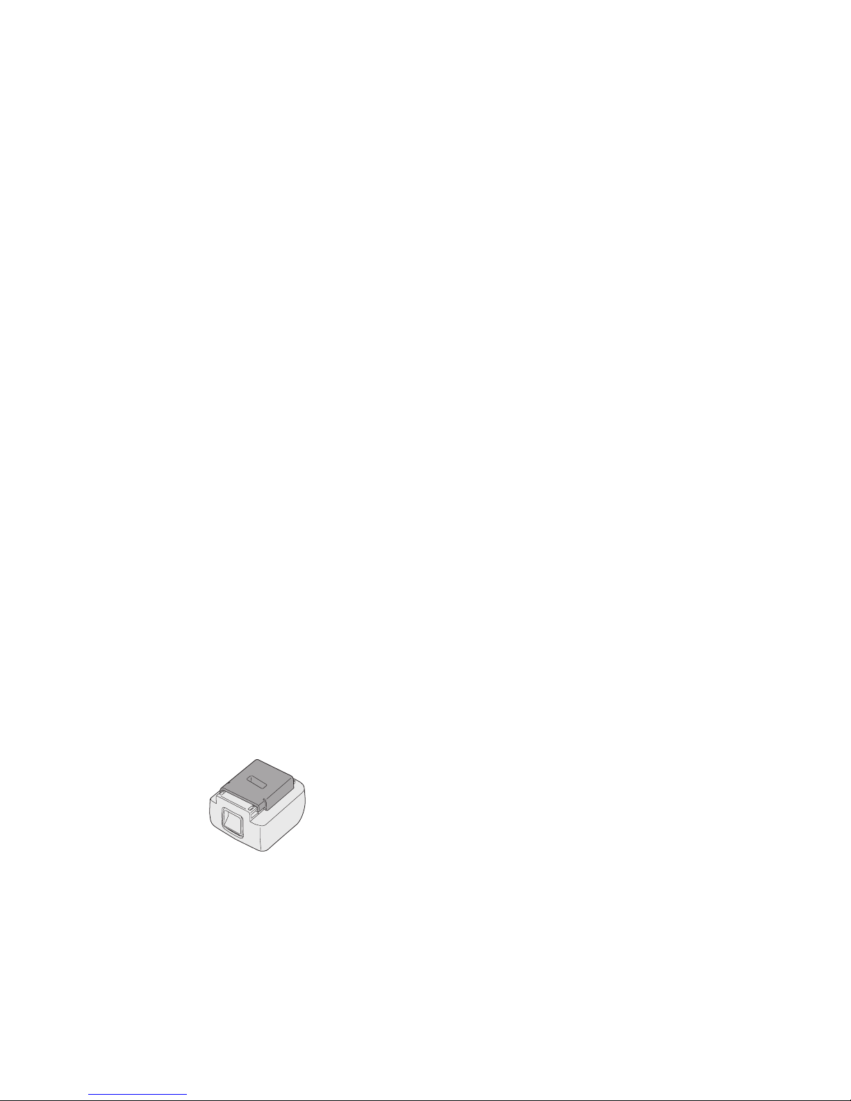
-
30 -
[Akku]
Für richtigen Gebrauch des
Akkus
Li-Ion-Akku
• Um eine möglichst lange Lebensdauer des
Li-Ion-Akkus zu erzielen, lagern Sie ihn
nach dem Gebrauch, ohne ihn aufzuladen.
•
Achten Sie beim Laden des Akkus darauf,
dass die Kontakte am Ladegerät frei von
Fremdstoffen, wie z. B. Staub und Wasser
usw., sind. Reinigen Sie die Kontakte vor
dem Laden des Akkus, falls Fremdstoffe auf
den Kontakten vorhanden sind.
Die Lebensdauer der Akkukontakte kann
durch Anhaften von Fremdstoffen, wie z.
B. Staub und Wasser usw., während des
Betriebs beeinträchtigt werden.
• Wenn Sie den Akku nicht benutzen,
halten Sie ihn von Metallgegenständen
fern: Büroklammern, Münzen, Schlüssel, Nägel, Schrauben oder andere kleine
Metallgegenstände können die Kontakte
kurzschließen.
Das Kurzschließen der Akkukontakte kann
Funken, Verbrennungen oder einen Brand
verursachen.
•
Sorgen Sie bei Benutzung des Akkus
für ausreichende Belüftung des Arbeitsplatzes.
• Wenn der Akku vom Werkzeug-Hauptteil
abgenommen wird, ist die Akkuabdeckung
sofort anzubringen, um zu verhüten, dass
die Akkukontakte durch Staub oder Schmutz
verunreinigt werden und ein Kurzschluss
verursacht wird.
Lebensdauer des Akkus
Der Akku hat nur eine begrenzte Lebensdauer. Wenn auch nach einer ordnungsgemäßen Ladung die Betriebszeit extrem
kurz ist, muss der Akku erneuert werden.
Batterie-Recycling
ACHTUNG:
Um Umweltschutz und Material-Recycling zu gewährleisten, müssen Sie die
Batterie zur örtlichen Entsorgungsstelle
bringen, falls eine solche in Ihrem Land
vorhanden ist.
[Ladegerät]
Laden
Lesen Sie die Gebrauchsanleitung des
Panasonic Ladegerätes durch, bevor Sie den
Akku auaden.
Vor dem Aufladen des
Akkus
Laden Sie den Akku bei einer Temperatur von
5°C bis 40°C.
Bei Temperaturen unter 5°C kann der Akku
nicht geladen werden. Falls die Temperatur des
Akkus unter 5°C liegt, nehmen Sie zuerst den
Akku aus dem Ladegerät heraus, und lassen
Sie ihn eine Stunde lang an einem Ort liegen,
der eine Temperatur von 5°C oder höher hat.
Laden Sie dann den Akku erneut auf.
 Loading...