

Panasonic EY7840X, EY7840LN2S, EY7840 Operating Instructions Manual
Cordless Rotary Hammer Drill & Driver
Perceuse/Visseuse rotative à percussion sans l
Destornillador y martillo de taladro rotatorio sin cables
Operating Instructions
Instructions d'utilisation
Manual de instrucciones
Model No: EY7840
IMPORTANT
This manual contains safety information. Read manual completely before first using this product and save this
manual for future use.
IMPORTANT
Ce mode d’emploi contient des informations sur la sécurité. Lisez-le en entier avant d’utiliser le produit et
conservez-le pour référence.
IMPORTANTE
Este manual contiene información de seguridad. Lea completamente este manual antes de utilizar por primera
vez este producto, y guárdelo para poder consultarlo en el futuro.
-
2 -
Index/Index/Indice
English: Page 4
Français: Page 17
Español: Página 32
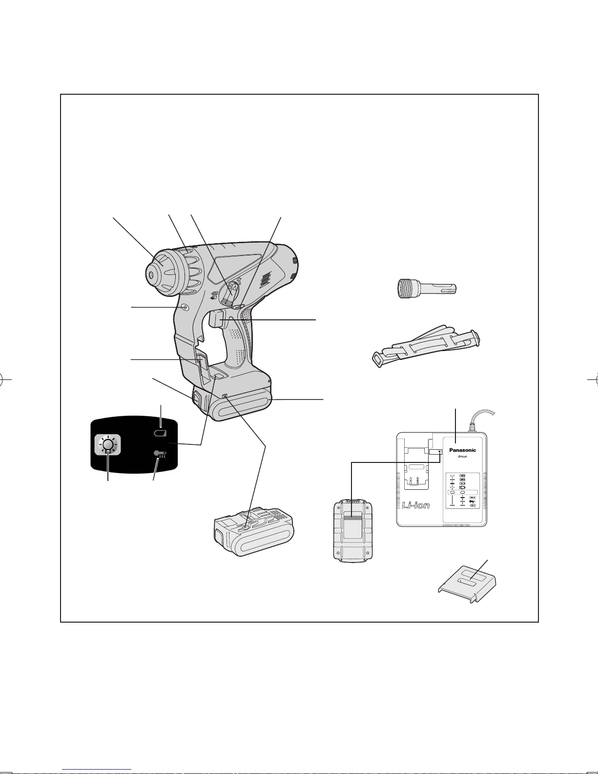
FUNCTIONAL DESCRIPTION
DESCRIPTION DES FONCTIONS
DESCRIPCIÓN FUNCIONAL
(A) (C) (D)
(E)
(F)
(M)
(N)
(L)
(R)
10.8 V ─ 28.8 V
(Q)
(G)
(G)
(H)
(I)
(K)
(J)
(O)
(P)
(B)

-
3 -
(A)
Chuck Mandrin Portabroca
(B)
Clutch handle Poignée de l’embrayage Mango de embrague
(C)
Hammering/drilling switching
lever
Commutateur martelage/
perforation
Palanca de conmutación de
martillo/taladro
(D)
Forward/Reverse lever
Levier d’inversion marche
avant-marche arrière
Palanca de avance/inversión
(E)
Variable speed control trigger
Gâchette de commande de
vitesse
Disparador del control de
velocided variable
(F)
Battery pack Batterie autonome Batería
(G)
Alignment marks Marques d’alignement Marcas de alineación
(H)
Control panel
Panneau de commande Panel de controle
(I)
Overheat warning lamp
(battery)
Témoin d’avertissement de
surchauffe (batterie)
Luz de advertencia de sobrecalentamiento (batería)
(J)
LED light ON/OFF button
Bouton Marche/Arrêt de la
lumière DEL
Botón ON/OFF de luz LED
(K)
Battery low warning lamp
Témoin d’avertissement de
batterie basse
Luz de aviso de baja carga de
batería
(L)
Battery pack release button
Bouton de libération de batterie autonome
Botón de liberación de batería
(M)
Bit adapter holder Porte-adaptateur de mèche Soporte de adaptador de broca
(N)
LED light Lumière DEL Luz indicadora
(O)
Bit adapter (EY9HX403E)
Adaptateur de mèche (EY9HX403E)
Adaptador de broca (EY9HX403E)
(P)
Shoulder strap
Dragonne Correa al hombro
(Q)
Battery charger
Chargeur de batterie Cargador de batería
(R)
Pack cover
Couvercle de la batterie
autonome
Cubierta de batería

-
4 -
This tool, as a complete unit with a battery
pack, satisfies appropriate IP Degrees of Protection based on the IEC regulations.
Definition of IP code
IP5X: Ingress of dust is not totally pre-
vented, but dust shall not penetrate in a
quantity to interfere with satisfactory operation of the tool or to impair safety (In
case that the talcum powder under 75 μm
intrudes inside the tool)
IPX6: Water projected in powerful jets
against the tool from any direction shall
have no harmful effects (In case that, with
a nozzle of 12.5 mm inner diameter, approximately 100 L/min of normal temperature water is injected to the tool for 3 minutes from 3 meter distance)
LIMITED WARRANTY
The rating of IP56 qualifies this tool for
the minimum impact of water or dust, but
not for the assurance of performance in
such conditions. See Safety and Operating Instructions for further details for proper operation.
. INTRODUCTION
This tool is a Rotary Hammer for drilling in concrete. In addition, the tool
has a “rotation only mode” without
hammering. The mode is suitable for
drilling and screw-fastening.
.
GENERAL SAFE-
TY RULES
WARNING! Read all instructions
Failure to follow all instructions listed below
may result in electric shock, fire and/or
serious injury. The term “power tool” in all
of the warnings listed below refers to your
main operated (corded) power tool and
battery operated (cordless) power tool.
SAVE THESE INSTRUCTIONS
Work Area Safety
1) Keep work area clean and well lit.
Cluttered or dark areas invite acci-
dents.
2
) Do not operate power tools in ex-
plosive atmospheres, such as in
the presence of flammable liquids, gases or dust.
P
ower tools create sparks which
may ignite the dust or fumes.
3
)
Keep children and bystanders
away while operating a power tool.
Distractions can cause you to lose
control.
Electrical Safety
1)
Power tool plugs must match the
outlet. Never modify the plug in any
way. Do not use any adapter plugs
with earthed (grounded) power tools.
Unmodified plugs and matching outlets will reduce risk of electric shock.
2)
Avoid body contact with earthed or
grounded surfaces such as pipes,
radiators, ranges and refrigerators.
There is an increased risk of elec-
tric shock if your body is earthed or
grounded.
3
) Do not expose power tools to
rain or wet conditions.
W
ater entering a power tool will in-
crease the risk of electric shock.
4) Do not abuse the cord. Never use
the cord for carrying, pulling or
unplugging the power tool. Keep
cord away from heat, oil, sharp
edges or moving parts.
D
amaged or entangled cords in-
crease the risk of electric shock.
5
)
When operating a power tool outdoors, use an extension cord suitable for outdoor use.
Use of a cord suitable for outdoor use
reduces the risk of electric shock.
Personal Safety
1) Stay alert, watch what you are
doing and use common sense
when operating a power tool. Do
not use a power tool while you
are tired or under the influence of
drugs, alcohol or medication.
A moment of inattention while oper-
ating power tools may result in personal injury.
2) Use safety equipment. Always
wear eye protection.
S
afety equipment such as dust
mask, non-skid safety shoes, hard
hat, or hearing protection used for
appropriate conditions will reduce
personal injuries.
3
) Avoid accidental starting. Ensure
the switch is in the off position
before plugging in.

-
5 -
Carrying power tools with your fin-
ger on the switch or plugging in the
power tools that have the switch on
invites accidents.
4)
Remove any adjusting key or wrench
before turning the power tool on.
A wrench or a key left attached to a
rotating part of the power tool may
result in personal injury.
5
) Do not overreach. Keep proper
footing and balance at all times.
This enables better control of the
power tool in unexpected situations.
6) Dress properly. Do not wear
loose clothing or jewelry. Keep
your hair, clothing and gloves
away from moving parts.
Loose
clothes, jewelry or long hair
can be caught in moving parts.
7
)
If devices are provided for the
connection of dust extraction and
collection facilities, ensure these
are connected and properly used.
Use of these devices can reduce
dust related hazards.
Power Tool Use and Care
1)
Do not force the power tool. Use
the correct power tool for your
application.
The correct power tool will do the
job better and safer at the rate for
which it was designed.
2)
Do not use the power tool if the
switch does not turn it on and off.
Any power tool that cannot be con-
trolled with the switch is dangerous
and must be repaired.
3
)
Disconnect the plug from the power source and/or the battery pack
from the power tool before making
any adjustments, changing accessories, or storing power tools.
Such preventive safety measures
reduce the risk of starting the power tool accidentally.
4)
Store idle power tools out of the
reach of children and do not allow persons unfamiliar with the
power tool or these instructions
to operate the power tool.
Power tools are dangerous in the
hands of untrained users.
5) Maintain power tools. Check for
misalignment or binding of moving parts, breakage of parts and
any other condition that may affect the power tools operation. If
damaged, have the power tool repaired before use.
Many accidents are caused by
poorly maintained power tools.
6
)
Keep cutting tools sharp and clean.
Properly maintained cutting tools with
sharp cutting edges are less likely to
bind and are easier to control.
7) Use the power tool, accessories
and tool bits etc. in accordance
with these instructions and in the
manner intended for the particular type of power tool, taking into
account the working conditions
and the work to be performed.
Use of the power tool for operations
different from those intended could
result in a hazardous situation.
Battery Tool Use and Care
1)
Ensure the switch is in the off position before inserting battery pack.
Inserting battery pack into pow-
er tools that have the switch on invites accidents.
2
) Recharge only with the charger
specified by the manufacturer.
A charger that is suitable for one type
of battery pack may create a risk of fire
when used with another battery pack.
3) Use power tools only with specif-
ically designated battery packs.
Use
of any other battery packs may
create a risk of injury and fire.
4)
When battery pack is not in use,
keep it away from other metal objects like paper clips, coins, keys,
nails, screws, or other small metal
objects that can make a connection
from one terminal to another.
Shorting the battery terminals to-
gether may cause burns, or a fire.
5
) Under abusive conditions, liq-
uid may be ejected from battery;
avoid contact. If contact accidentally occurs, flush with water. If
liquid contacts eyes, additionally
seek medical help.
Liquid
ejected from the battery may
cause irritation or burns.
-
6 -
Service
1) Have your power tool serviced by
a qualified repair person using
only identical replacement parts.
T
his will ensure that the safety of
power tool is maintained.
. SPECIFIC SAFE-
TY RULES
1) Wear ear protectors. Exposure to
noise can cause hearing loss.
2)
Use auxiliary handles supplied
with the tool. Loss of control can
cause personal injury.
3) Hold power tools by insulated grip-
ping surfaces when performing an
operation where the cutting tool
may contact hidden wiring.
Contact with a “live” wire will make
exposed metal parts of the tool
“live” and shock the operator.
4)
Be aware that this tool is always in
an operating condition, since it does
not have to be plugged into an electrical outlet.
5) If the bit becomes jammed, immediately turn the trigger switch off
to prevent an overload which can
damage the battery pack or motor. Use reverse motion to loosen
jammed bits.
6)
Do not operate the Forward/Reverse
lever when the trigger switch is on.
The battery will discharge rapidly
and damage to the unit may occur.
7) When storing or carrying the tool,
set the Forward/Reverse lever to
the center position (switch lock).
8) Do not strain the tool by holding
the speed control trigger halfway
(speed control mode) so that the
motor stops. The protection circuit will activate and may prevent
speed control operation. If this happens, release the speed control
trigger and squeeze again for normal operation.
9) Be careful not to get dust inside the
chuck.
10) Do not touch the rotating parts to
avoid injury.
11)
Do not use the tool continuously for a
long period of time. Stop using the tool
from time to time to avoid temperature
rise and heat overload of the motor.
12) Do not drop the tool.
13)
Do not put the tool on the place
where the chuck is depressed. The
bit may come off from the chuck
and fall down when the chuck is depressed. It may cause injuries.
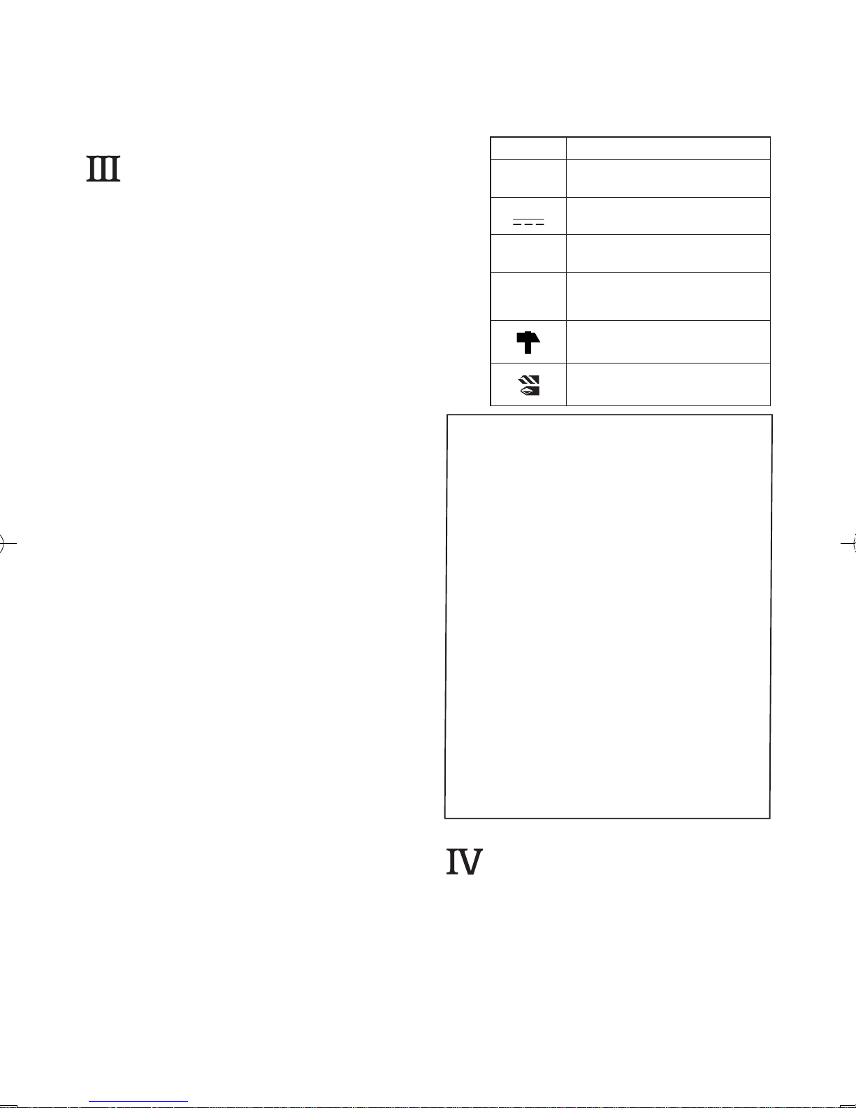
Symbol meaning
V Volts
Direct current
n
0
No load speed
… min
-1
Revolutions or
reciprocation per minutes
Rotation with hammering
Rotation only
WARNING:
Some dust created by power sanding, sawing, grinding, drilling, and
other construction activities contains chemicals known to the State
of California to cause cancer, birth
defects or other reproductive harm.
Some examples of these chemicals are:
*
Lead from lead-based paints
* Crystalline silica from bricks and
cement and other masonry products
*
Arsenic and chromium from chem-
ically-treated lumber.
To reduce your exposure to these
chemicals: work in a well ventilated
area, and work with approved safety equipment, such as dust masks
that are specially designed to filter
the microscopic particles.
. FOR BATTERY
CHARGER &
BATTERY PACK
Important Safety Instructions
1)
SAVE THESE INSTRUCTIONS -
This manual contains important
safety and operating instructions
for battery charger .

-
7 -
2) Before using battery charger, read
all instructions and cautionary markings on (1) battery charger, (2) battery pack.
3
) CAUTION
- To reduce the risk of injury, charge only Panasonic Battery
Pack as shown in last page.
Other types of batteries may burst
causing personal injury and damage.
4) Do not expose charger to rain or
snow.
5
) To reduce the risk of damaging the
electric plug and cord, pull by plug
rather than cord when disconnecting charger.
6
) Make sure cord is located so that it
will not be stepped on, tripped over,
or otherwise subjected to damage
or stress.
7
) An extension cord should not be
used unless absolutely necessary.
U
se of improper extension cord
could result in a risk of fire and
electric shock. If extension cord
must be used, make sure:
a.
that pins on plug of extension
cord are the same number, size
and shape as those of plug on
charger.
b.
that extension cord is proper-
ly wired and in good electrical
condition.
c.
that wire size is large enough
for ampere rating of charger as
specified below.
RECOMMENDED MINIMUM AWG SIZE OF
EXTENSION CORDS FOR
BATTERY CHARGERS
AC Input Rating.
Amperes
AWG Size of Cord
Equal to or
greater than
But less
than
Length of Cord, Feet
25 50 100 150
0 2 18 18 18 16
8) Do not operate charger with damaged cord or plug
replace them
immediately.
9
) Do not operate charger if it has re-
ceived a sharp blow, been dropped,
or otherwise damaged in any way;
take it to a qualified serviceman.
1
0) Do not disassemble charger; take
it to a qualified serviceman when
service or repair is required. Incorrect reassembly may result in a risk
of electric shock or fire.
1
1) To reduce the risk of electric shock,
unplug charger from outlet before
attempting any maintenance or
cleaning.
1
2) The charger and battery pack are
specifically designed to work together. Do not attempt to charge any
other cordless tool or battery pack
with this charger.
1
3) Do not attempt to charge the battery
pack with any other charger.
14) D
o not attempt to disassemble the
battery pack housing.
1
5) Do not store the tool and battery
pack in locations where the temperature may reach or exceed 50°C (122°F)
(such a metal tool shed, or a car in
the summer), which can lead to deterioration of the storage battery.
1
6) Do not charge battery pack when the
temperature is BELOW 0°C (32°F)
o
r ABOVE 40°C (104°F). This is very
important.
1
7) Do not incinerate the battery pack.
It can explode in a fire.
1
8) Avoid dangerous environment. Do not
use charger in damp or wet locations.
1
9) The charger is designed to operate
on standard household electrical
power only. Do not attempt to use it
on any other voltage!
2
0) Do not abuse cord. Never carry charger by cord or yank it to disconnect from outlet. Keep cord away
from heat, oil and sharp edges.
2
1) Charge the battery pack in a well
ventilated place, do not cover the
charger and battery pack with a
cloth, etc., while charging.
2
2) Use of an attachment not recommended may result in a risk of fire,
electric shock, or injury to persons.
2
3) Do not short the battery pack. A battery short can cause a large current
flow, over heating and burns.
24) N
OTE: If the supply cord of this appliance is damaged, it must only be replaced by a repair shop appointed by
the manufacturer, because special
purpose tools are required.
2
5) TO REDUCE THE RISK OF ELECTRIC SHOCK, THIS APPLIANCE
HAS A POLARIZED PLUG (ONE
BLADE IS WIDER THAN THE
OTHER).
-
8 -
This plug will fit in a polarized outlet
only one way. If the plug does not fit
fully in the outlet, reverse the plug. If
it still does not fit, contact a qualified
electrician to install the proper outlet.
Do not change the plug in any way.
WARNING:
• Do not use other than the Panasonic
battery packs that are designed for
use with this rechargeable tool.
• Panasonic is not responsible for any
damage or accident caused by the
use of the recycled battery pack and
the counterfeit battery pack.
•
Do not dispose of the battery pack in
a fire, or expose it to excessive heat.
•
Do not drive the likes of nails into the
battery pack, subject it to shocks,
dismantle it, or attempt to modify it.
•
Do not allow metal objects to touch
the battery pack terminals.
•
Do not carry or store the battery
pack in the same container as nails
or similar metal objects.
•
Do not charge the battery pack in a
high-temperature location, such as
next to a fire or in direct sunlight.
Otherwise, the battery may overheat, catch fire, or explode.
•
Never use other than the dedicated
charger to charge the battery pack.
Otherwise, the battery may leak,
overheat, or explode.
•
After removing the battery pack from
the drill or the charger, always reattach the back cover. Otherwise, the
battery contacts could be shorted,
leading to a risk of fire.
• When the Battery Pack Has Deteriorated, Replace It with a New One.
Continued use of a damaged battery
pack may result in heat generation, ignition or battery rupture.
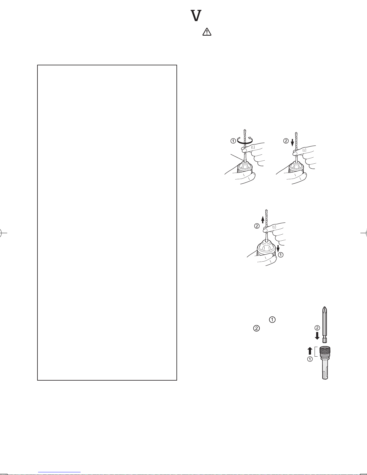
. ASSEMBLY
CAUTION:
Use of a concrete drill bit larger than
the recommended size may cause
damage to the tool.
1. To insert the bit
1
-1. Insert a bit into the mounting hole, and
turn it slightly to locate an engaged
position.
1
-2. At the engaged position, push the bit
as far as it goes. Make sure that the
bit is fixed by pulling it.
2. To remove the bit
2-1.
Depress the chuck and pull the bit.
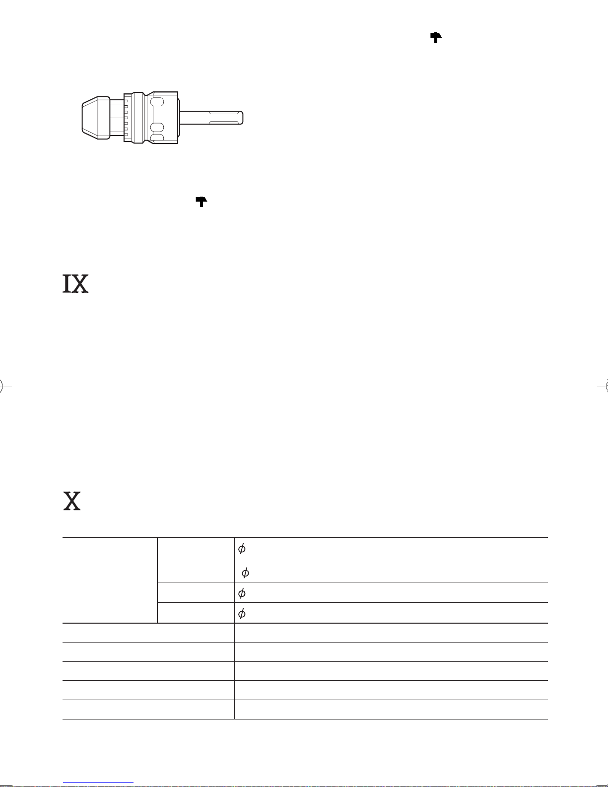
Bit adapter
Use a bit adapter (O) and bit.
1. Remove the bit adapter from
the bit adapter holder on the
main unit.
2.
Pull the bit holder. (
)
3. Insert the bit. (
)
Bit
holder
4. Make sure the bit is inserted
firmly by pulling it lightly.
5.
Insert the bit adapter into the
mounting hole and turn to
locate an engaged position.
6.
At the engaged position,
push in as far as it goes.
•
Make sure it does not move by
pulling it lightly.
SDS PLUS type
shank
-
9 -
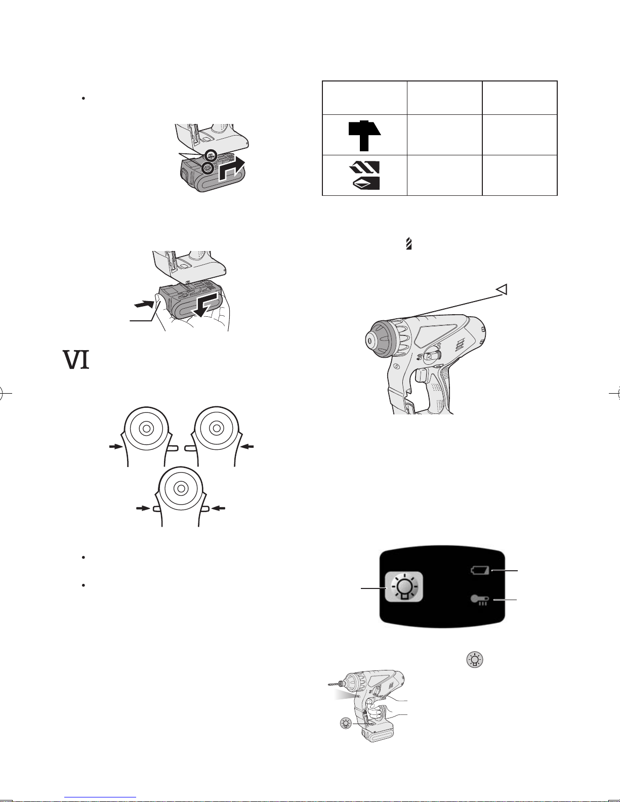
Attaching or Removing Battery Pack
1.
To connect the battery pack:
Line up the alignment marks and attach
the battery pack.
Slide the battery pack until it locks into
position.
Alignment marks
2.
To remove the battery pack:
Push on the button from the front to re-
lease the battery pack.
Button
. OPERATION
Forward/Reverse Lever
ReverseForward
Lock
Be sure to set the lever in the center
to lock it after use.
Operate the Forward/Reverse lever
after the motor rotation is completely
stopped.
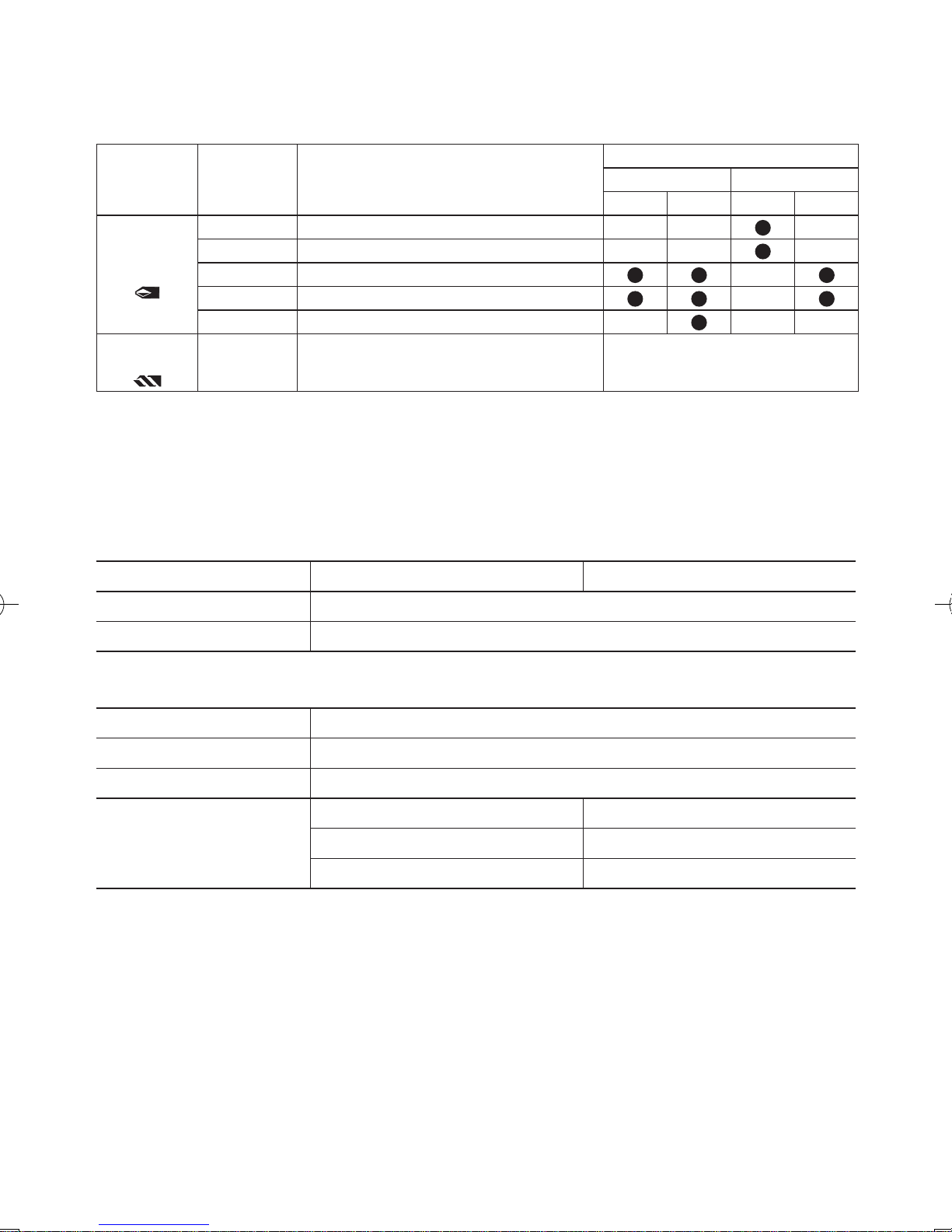
Hammering/Drilling Switching Lever
NOTE: Operate the mode change after
the motor rotation is completely
stopped.
Position of
switching lever
Action mode Operation
Rotation with
hammering
Concrete
Drilling,
Block Drilling
Rotation only
Screw
Fastening,
Drilling
Clutch Torque Setting
Adjust the torque to one of the 5 clutch
settings or “
” position.
CAUTION:
Test the setting before actual operation.
Set the scale at this mark ( ).
Variable Speed Control Trigger
To set the center of a hole, pull the
trigger slightly to start the drill rotation
slowly.
The more the speed control trigger is
pulled, the higher the speed becomes.
Control Panel
(1)
(2)
(3)
(1) LED light
Pressing toggles the
LED light on and off.
The light illuminates with
very low current, and it
does not adversely affect the performance of
the driver during use or its
battery capacity.
-
10 -
CAUTION:
• The built-in LED light is designed to
illuminate the small work area temporarily.
•
Do not use it as a substitute for a
regular
flashlight, since it does not
have enough brightness
.
This product has the built-in LED light.
This product is classified into “Class 1
LED Product” to IEC (EN) 60825-1:2001.
LED RADIATION
DO NOT STARE INTO BEAM
CLASS 1 LED PRODUCT
Use of controls or adjustments or performance of procedures other than those speci-
ed herein may result in hazardous radiation
exposure.
(2) Overheat warning lamp
Off
(normal
operation)
Flashing: Overheat
Indicates operation has
been halted due to battery
overheating.
The overheating protection feature
halts tool operation to protect the
b
attery pack in the event of overheating. The overheat warning lamp
on the control panel flashes when
this feature is active.
•
If the overheating protection feature
activates, allow the tool to cool
thoroughly (at least 30 minutes).
The driver is ready for use when the
overheat warning lamp goes out.
•
Avoid using the tool in a way that
causes the overheating protection
feature to activate repeatedly.
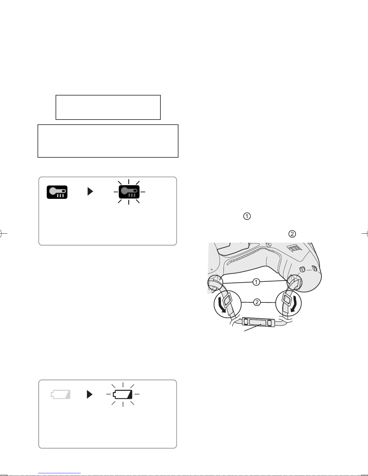
(3)
Battery low warning lamp
Off
(normal
operation)
Flashing
(No charge)
Battery protection
feature active
The battery protection feature activates immediately before the battery
loses its charge, causing the battery
low warning lamp to flash.
•
If you notice the battery low warning
lamp flashing, charge the battery
pack immediately.
Installing the Shoulder Strap
CAUTION:
• Install the shoulder strap firmly to
the main unit of the tool and check
the length of the strap before use.
•
Check the condition of the strap
and do not use if it is cut or torn
etc.
There
is a risk of injury or damage
if used while improperly installed.
•
Please wear the shoulder strap se-
curely on the shoulder.
There
is a risk of injury or damage
if it is accidentally dropped.
1
. Pass the strap through the strap
holders. (
)
2. Pass the strap through the buckles
and adjust the length. (
)
Shoulder pad
• The shoulder strap can be adjusted
according to the individual.
• Adjust the shoulder pad to the
shoulder.
•
Pull the shoulder strap to make
sure it is firmly attached to the main
unit of the tool.

-
11 -
[Battery Pack]
For Appropriate Use of Bat-
tery pack
• For optimum battery life, store the Liion battery pack following use without
charging it.
• When charging the battery pack, confirm that the terminals on the battery charger are free of foreign substances such as dust and water etc.
Clean the terminals before charging
the battery pack if any foreign substances are found on the terminals.
The life of the battery pack terminals
may be affected by foreign substances
such as dust and water etc. during
operation.
• When battery pack is not in use,
keep it away from other metal objects
like: paper clips, coins, keys, nails,
screws, or other small metal objects
that can make a connection from one
terminal to another.
Shorting the battery terminals togeth-
er may cause sparks, burns or a fire.
• When operating the battery pack,
make sure the work place is well ventilated.
• When the battery pack is removed
from the main body of the tool, replace
the battery pack cover immediately in
order to prevent dust or dirt from contaminating the battery terminals and
causing a short circuit.
Battery Pack Life
The rechargeable batteries have a
limited life. If the operation time becomes extremely short after recharging, replace the battery pack with a
new one.
Battery Recycling
ATTENTION:
FOR Li-ion Battery Pack
A Li-ion battery that is recyclable powers
the product you have purchased. Please
call 1-800-8-BATTERY for information on
how to recycle this battery.
[Battery Charger]
Charging
Cautions
• The ambient temperature range is between 0°C (32°F) and 40°C (104°F).
If the battery pack is used when the
battery temperature is below 0°C
(32°F), the tool may fail to function
properly.
• Use the charger at temperatures between 0°C and 40°C, and charge the
battery at a temperature similar to that
of the battery itself. (There should be
no more than a 15°C difference between the temperatures of the battery
and the charging location.)
• When charging a cool battery pack
(below 0°C (32°F)) in a warm place,
leave the battery pack at the place
and wait for more than one hour to
warm up the battery to the level of
the ambient temperature.
•
Cool down the charger when charging
more than two battery packs consecutively.
• Do not insert your fingers into contact
hole, when holding charger or any
other occasions.
To prevent the risk of fire or damage
to the battery charger.
• Do not use power source from an
engine generator.
• Do not cover vent holes on the
charger and the battery pack.
• Unplug the charger when not in
use.
-
12 -
Li-ion Battery Pack
NOTE:
Your battery pack is not fully charged at the time of purchase. Be sure
to charge the battery before use.
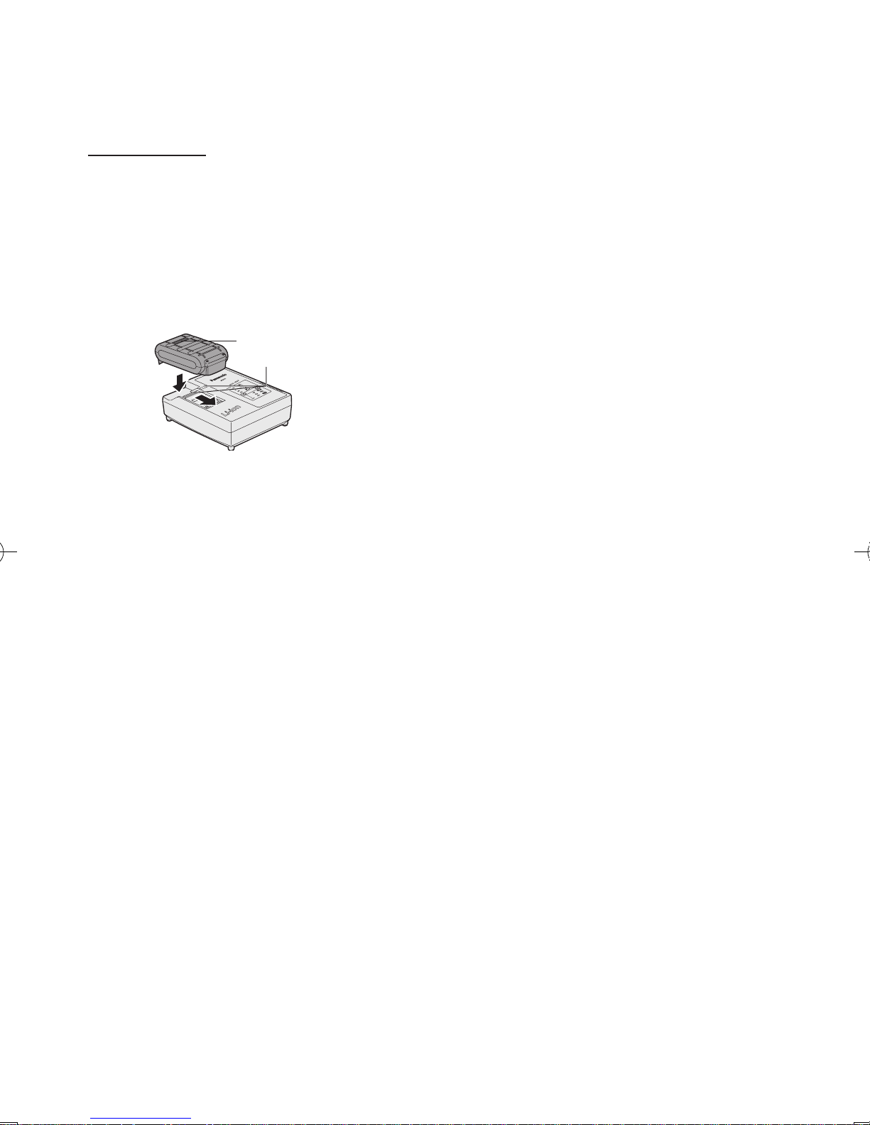
Battery charger
1. Plug the charger into the AC outlet.
2.
Insert the battery pack firmly into the
charger.
1 Line up the alignment marks and
place the battery onto the dock on
the charger.
2 Slide
forward in the direction of the
arrow.
Alignment marks
3.
During charging, the charging lamp will
be lit.
When charging is completed, an internal electronic switch will automatically
be triggered to prevent overcharging.
• Charging will not start if the battery
pack is warm (for example, immediately after heavy-duty operation).
The orange standby lamp will be
flashing until the battery cools down.
C
harging will then begin automati-
cally.
4
. The charge lamp (green) will flash
slowly once the battery is approximately 80% charged.
5
. When charging is completed, the
charging lamp in green color will turn
off.
6.
If the temperature of the batter pack is
0°C or less, charging takes longer to
fully charge the battery pack than the
standard charging time.
Even when the battery is fully charged,
it will have approximately 50% of the
power of a fully charged battery at normal operating temperature.
7.
Consult an authorized dealer if the
charging lamp (green) does not turn off.
8. If a fully charged battery pack is inserted into the charger again, the charging
lamp lights up. After several minutes,
the charging lamp in green color will
turn off.
-
13 -
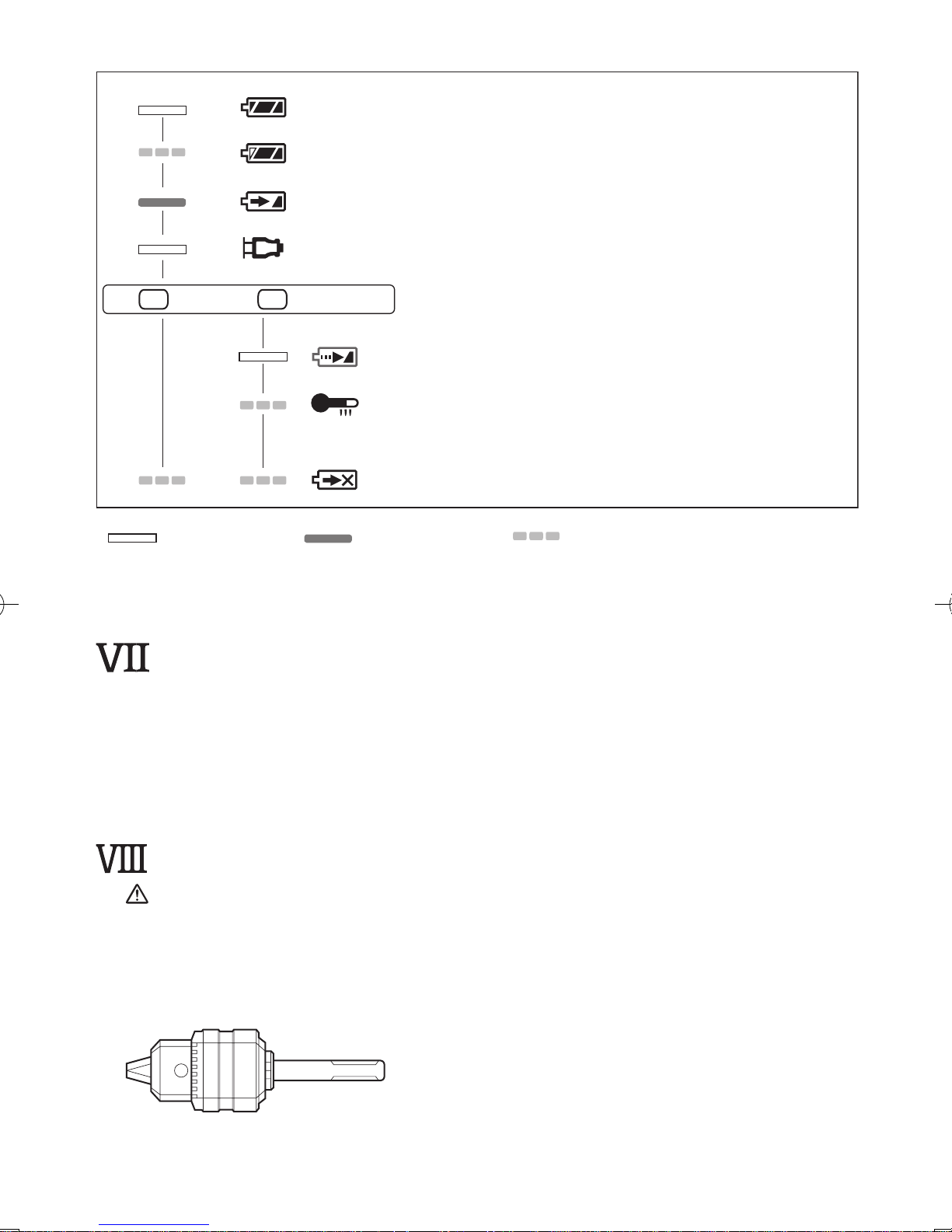
LAMP INDICATIONS
Charging is completed. (Full charge.)
Battery is approximately 80% charged.
Now charging.
Charger is plugged into the AC outlet. Ready to charge.
Charging Status Lamp.
Left: green Right: orange will be displayed.
Battery pack is cool.
The battery pack is being charged slowly to reduce the load on the battery.
Battery pack is warm.
Charging will begin when temperature of battery pack drops. If the temperature of the
battery pack is -10° or less, the charging status lamp (orange) will also start flashing .
Charging will begin when the temperature of the battery pack goes up"
Charging is not possible. Clogged with dust or malfunction of the battery pack.
Turn off Lit Flashing
(Green) (Orange)
. MAINTENANCE
• Use only a dry, soft cloth for wiping the unit. Do not use a damp cloth, thinner,
benzine, or other volatile solvents for cleaning.
• In the event that the inside of the tool or battery pack is exposed to water, drain
and allow to dry as soon as possible. Carefully remove any dust or iron filings
that collect inside the tool. If you experience any problems operating the tool,
consult with a repair shop.
. ACCESSORIES
CAUTION:
To prevent the risk of injury, only use accessory or attachment for its stated purpose.
Bit adapter (included)
•EY9HX
403E
Drill chuck (Optional accessory)
•EY9HX
400E
-
14 -
Use with wood drill bit or metal drill bit with shank of 1.5 mm to 13 mm diameter.
Do not use the drill chuck in “Rotation with hammering mode” (
). Use in "Rotation
with hammering mode" may cause break of chuck or bit and result in injury.
Hammer chuck (Optional accessory)
•EY9HX
401E
Use with concrete drill bit, wood drill bit or metal drill bit with straight shank of 2.5 mm
to 13 mm diameter.
Do not use the hammer chuck with wood drill bit or metal drill bit in “Rotation with
hammering mode” (
). Use in “Rotation with hammering mode” may cause break of
bit and result in injury.
If you need any assistance for more details regarding these accessories, ask your
local service center.
. USAGE SUGGESTION
1. If there isn’t enough force pushing down on the bit, the tool may not be able to
blow in hammering mode.
This is to prevent the hammering mode from operating with no load. Press down
harder on the bit to engage the tool and cause it to blow.
Always be sure to press down with enough force when working.
2. In winter or in other situations where the temperature of the unit is low (5°C (41°F)
or below), the blow of the hammering mode may be weaker than normal at the
beginning stage.
This is because the grease becomes stiffer in low temperatures, increasing fric-
tion.
If this should happen, operating hammering mode with no load for approximately
30 seconds and repeat this 3 times. This will restore its blowing power.
. SPECIFICATIONS
MAIN UNIT
Maximum drilling
diameter
Concrete
16.5 mm (21/32")*
*For work that can be completed with one battery pack.
( 12.5 mm (15/32") - 16.5 mm (21/32"))
Steel
13 mm (33/64")
Wood
18 mm (23/32")
Motor voltage 1
4.4 V DC
Speed at no load (RPM) 0-1000 min
-1
(rpm)
Blows rate per minute (BPM) 0-3800 min
-1
(bpm)
Weight (with battery pack) 2.
4 kg (5.3 lbs)
Overall length 2
49 mm (9-51/64")
-
15 -
GUIDELINE TABLE
• Select the torque for fastening screws with the clutch handle.
• Guide for the selection of torque
Depending on the job, adjustments are possible in five levels by approximately 1 N•m
(10 kgf-cm) increments.
Setting Torque
Guide Depending on Material
Concrete Block
(A) (B) (A) (B)
Fastening
Screws
1 Approximately 1.5 N•m (15 kgf-cm)
2 Approximately 2.5 N•m (25 kgf-cm)
3 Approximately 3.4 N•m (35 kgf-cm)
4 Approximately 4.4 N•m (45 kgf-cm)
5 Approximately 5.4 N•m (55 kgf-cm)
Drilling
Holes (Drill Mark) Approximately 10.5 N•m (107 kgf-cm)
Drilling holes in wood and
metal
(A) For fastening screws into plastic anchor which requires dia. 6.0 mm (1/4") prehole in the concrete.
(B) For directly fastening screws into concrete (like topcon) with dia. 3.5 mm (1/8") prehole.
NOTE: This is only a rough guide. Required torque is different depending on the
shape, material, and application of the screws.
Set according to the work environment of the site.
BATTERY PACK
Model EY9L41 EY9L42
Storage battery Li-ion Battery
Battery voltage 14.4 V DC (3.6 V x 4 cells)
BATTERY CHARGER
Model EY0L81
Electrical rating See the rating plate on the bottom of the charger.
Weight 0.93 kg (2 lbs)
Charging time
EY9L41 EY9L42
Usable: 45 min. Usable: 30 min.
Full: 60 min. Full: 35 min.
NOTE: This chart may include models that are not available in your area.
Please refer to the latest general catalogue.
 Loading...