

Page 1
Cordless Impact Wrench
Destornillador de impacto inalámbrico
Perceuse à impact sans l
Operating Instructions
Instructions d’utilisation
Manual de instrucciones
Model No : EY7552
IMPORTANT
Before operating this unit, please read these instructions completely and save this manual for future use.
IMPORTANT
Lire entièrement les instructions suivantes avant de faire fonctionner l’appareil et conserver ce mode d’emploi
à des fins de consultation ultérieure.
IMPORTANTE
Antes de usar este aparato por primera vez, lea todas las instrucciones de este manual y guarde el manual
para poderlo consultar en el futuro.
Register online at www.panasonic.com/register
Page 2
Index/Index/Indice
English: Page 3 Français: Page 17 Español: Página 31
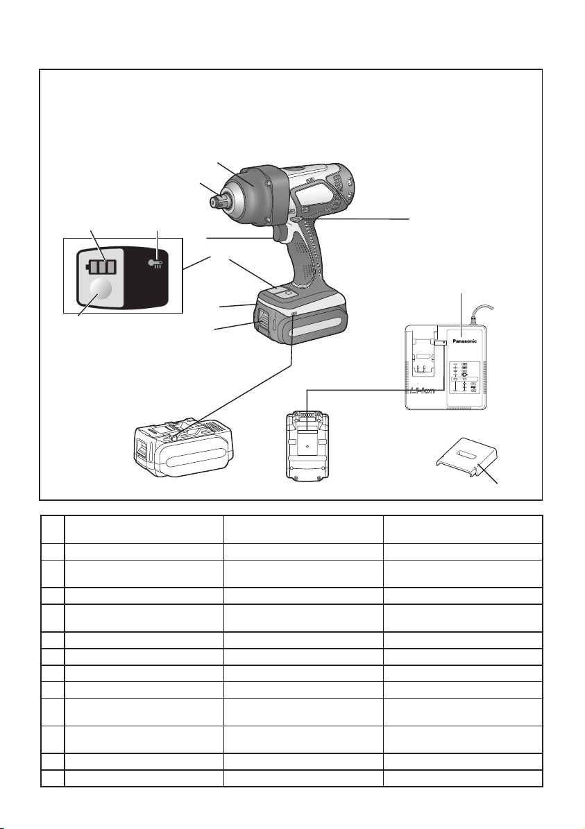
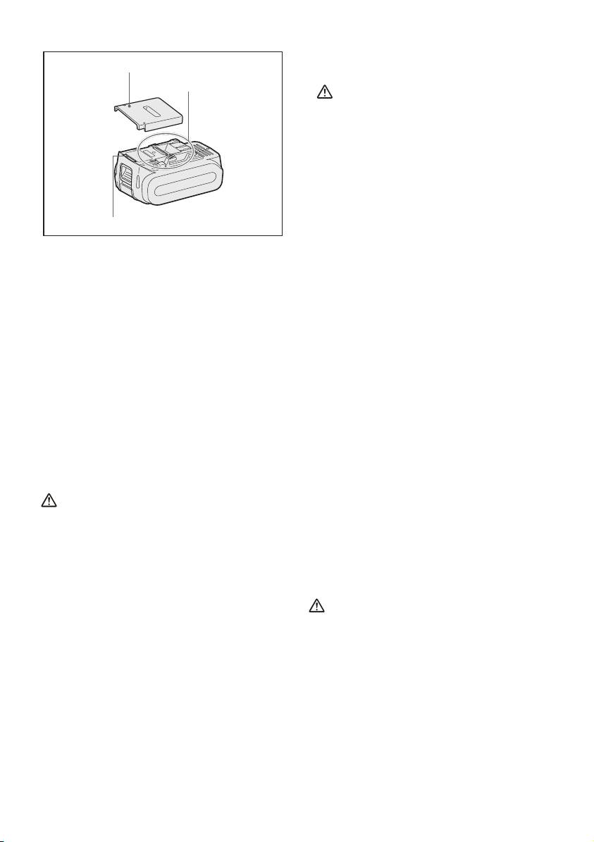
FUNCTIONAL DESCRIPTION
DESCRIPTION DES FONCTIONS
DESCRIPCIÓN FUNCIONAL
(B)
(A)
(I)
(J)
(C)
(K)
(G)
(L)
(F)
(H)
(E)
10.8 V ─ 28.8 V
(D)
Square drive (retainer ring and pin) Embout carré (bague et goupille de
(A)
Nose protector Protection du bec Protector del morro
(B)
Forward/Reverse lever Levier d’inversion marche avant/
(C)
Alignment marks Marques d’alignement Marcas de alineación
(D)
Battery pack release button Bouton de libération de batterie
(E)
Battery pack Batterie autonome Batería
(F)
Indication panel Panneau indicateur Panel de indicación
(G)
Battery level button Bouton du niveau de la batterie Botón de nivel de batería
(H)
Battery level indicator Indicateur du niveau de la batterie Indicador de nivel de batería
(I)
Overheat warning lamp (motor/
(J)
battery)
Variable speed control trigger Gâchette de commande de vitesse Disparador del control de velocidad
(K)
Battery charger Chargeur de batterie Cargador de batería
(L)
Pack cover Couvercle de la batterie autonome Cubierta de batería
(M)
retenue)
marche arrière
autonome
Témoin d’avertissement de
surchauffe (moteur/batterie)
Adaptador para puntas (anillo de
retención y pasador)
Palanca de avance/marcha atrás
Botón de liberación de batería
Luz de advertencia de
sobrecalentamiento (motor/batería)
variable
(M)
-
2 -
Page 3
This tool, as a complete unit with a battery
pack, satises appropriate IP Degrees of
Protection based on the IEC regulations.
Definition of IP code
IP5X: Ingress of dust is not totally
prevented, but dust shall not penetrate
in a quantity to interfere with satisfactory
operation of the tool or to impair safety (In
case that the talcum powder under 75 μm
intrudes inside the tool).
IPX6: Water projected in powerful jets
against the tool from any direction shall
have no harmful effects (In case that,
with a nozzle of 12.5 mm inner diameter,
approximately 100 L/min of normal
temperature water is injected to the tool for
3 minutes from 3 meter distance).
LIMITED WARRANTY
The rating of IP56 qualifies this tool for
the minimum impact of water or dust, but
not for the assurance of performance in
such conditions. See Safety and Operating
Instructions for further details for proper
operation.
I. GENERAL
SAFETY RULES
WARNING! Read all instructions
Failure to follow all instructions listed below
may result in electric shock, re and/or
serious injury. The term “power tool” in all
of the warnings listed below refers to your
mains operated (corded) power tool and
battery operated (cordless) power tool.
SAVE THESE INSTRUCTIONS
Work Area Safety
1) Keep work area clean and well lit.
Cluttered or dark areas invite accidents.
2) Do not operate power tools in explosive
atmospheres, such as in the presence of
flammable liquids, gases or dust.
Power tools create sparks which may ignite
the dust or fumes.
3) Keep children and bystanders away while
operating a power tool.
Distractions can cause you to lose control.
Electrical Safety
1) Power tool plugs must match the outlet.
Never modify the plug in any way. Do
not use any adapter plugs with earthed
(grounded) power tools.
Unmodified plugs and matching outlets will
reduce risk of electric shock.
2) Avoid body contact with earthed or
grounded surfaces such as pipes,
radiators, ranges and refrigerators.
There is an increased risk of electric shock if
your body is earthed or grounded.
3) Do not expose power tools to rain or wet
conditions.
Water entering a power tool will increase the
risk of electric shock.
4) Do not abuse the cord. Never use the
cord for carrying, pulling or unplugging
the power tool. Keep cord away from
heat, oil, sharp edges or moving parts.
Damaged or entangled cords increase the
risk of electric shock.
5) When operating a power tool outdoors,
use an extension cord suitable for
outdoor use.
Use of a cord suitable for outdoor use
reduces the risk of electric shock.
6) If operating a power tool in a damp
location is unavoidable, use a residual
current device (RC D) protected supply.
Use of RCD reduces the risk of electrical
shock.
Personal Safety
1) Stay alert, watch what you are doing and
use common sense when operating a
power tool. Do not use a power tool while
you are tired or under the influence of
drugs, alcohol or medication.
A moment of inattention while operating
power tools may result in personal injury.
2) Use safety equipment. Always wear eye
protection.
Safety equipment such as dust mask, non-
skid safety shoes, hard hat, or hearing
protection used for appropriate conditions
will reduce personal injuries.
3) Avoid accidental starting. Ensure the
switch is in the off position before
plugging in.
Carrying power tools with your finger on the
switch or plugging in the power tools that
have the switch on invites accidents.
-
3 -
Page 4

4) Do not overreach. Keep proper footing
and balance at all times.
This enables better control of the power
tool in unexpected situations.
5) Dress properly. Do not wear loose
clothing or jewellery. Keep your hair,
clothing and gloves away from moving
parts.
Loose clothes, jewellery or long hair can be
caught in moving parts.
6) If de vices are pr ovided for the
connection of dust extraction and
collection facilities, ensure these are
connected and properly used.
Use of these devices can reduce dust
related hazards.
Power Tool Use and Care
1) Do not force the power tool. Use the
correct power tool for your application.
The correct power tool will do the job
better and safer at the rate for which it was
designed.
2) Do not use the power tool if the switch
does not turn it on and off.
Any power tool that cannot be controlled
with the switch is dangerous and must be
repaired.
3) Disconnect the plug from the power
source and/or the battery pack from
the power tool before making any
adjustments, changing accessories, or
storing power tools.
Such preventive safety measures reduce the
risk of starting the power tool accidentally.
4) Store idle power tools out of the reach
of children and do not allow persons
unfamiliar with the power tool or these
instructions to operate the power tool.
Power tools are dangerous in the hands of
untrained users.
5) Maintain power tools. Check for
misalignment or binding of moving parts,
breakage of parts and any other condition
that may affect the power tools operation.
If damaged, have the power tool repaired
before use.
Many accidents are caused by poorly
maintained power tools.
6) Keep cutting tools sharp and clean.
Properly maintained cutting tools with sharp
cutting edges are less likely to bind and are
easier to control.
7) Use the power tool, accessories and
tool bits etc. in accordance with these
instructions and in the manner intended
for the particular type of power tool, taking
into account the working conditions and
the work to be performed.
Use of the power tool for operations different
from those intended could result in a
hazardous situation.
Battery Tool Use and Care
1) Ensure the switch is in the off position
before inserting battery pack.
Inserting battery pack into power tools that
have the switch on invites accidents.
2) Recharge only with the charger specified
by the manufacturer.
A charger that is suitable for one type of
battery pack may create a risk of fire when
used with another battery pack.
3) Use power tools only with specifically
designated battery packs.
Use of any other battery packs may create a
risk of injury and fire.
4) When battery pack is not in use, keep it
away from other metal objects like paper
clips, coins, keys, nails, screws, or other
small metal objects that can make a
connection from one terminal to another.
Shorting the battery terminals together may
cause burns, or a fire.
5) Under abusive conditions, liquid may
be ejected from battery; avoid contact.
If contact accidentally occurs, flush with
water. If liquid contacts eyes, additionally
seek medical help.
Liquid ejected from the battery may cause
irritation or burns.
Service
1) Have your power tool serviced by a
qualified repair person using only
identical replacement parts.
This will ensure that the safety of power tool
is maintained.
-
4 -
Page 5
II. SPECIFIC
SAFETY RULES
1) Wear ear protection. Exposure to noise can
cause hearing loss.
2) Be aware that this tool is always in an
operating condition, since it does not have to
be plugged into an electrical outlet.
3) Hold power tools by insulated gripping
surfaces when performing an operation
where the cutting tool may contact hid
den wiring.
Contact with a “live” wire will make exposed
metal parts of the tool “live” and shock the
operator.
4) If the socket becomes jammed, immediately
turn the trigger switch off to prevent an
overload which can damage the battery
pack or motor. Use reverse motion to loosen
jammed sockets.
5) Do NOT operate the Forward/Reverse lever
when the trigger switch is on. The battery
will discharge rapidly and damage to the unit
may occur.
6) When storing or carrying the tool, set the
Forward/Reverse lever to the center position
(switch lock).
7) Do not strain the tool by holding the speed
control trigger halfway (speed control mode)
so that the motor stops. The protection circuit
will activate and may prevent speed control
operation. If this happens, release the speed
control trigger and squeeze again for normal
operation.
8) Be careful not to get dust inside the chuck.
9) Do not touch the rotating parts to avoid injury.
10) Do not use the tool continuously for a long
period of time. Stop using the tool from time
to time to avoid temperature rise and heat
overload of the motor.
11) Do not drop the tool.
Symbol Meaning
V
n
0
… min
Revolutions or reciprocations
-1
Volts
Direct current
No load speed
per minutes
Ah
Electrical capacity of battery
pack
To reduce the risk of
injury user must read and
understand instruction
manual.
WARNING!
Some dust created by power sanding,
sawing, grinding, drilling, and other
construction activities contains chemicals
known to the State of California to cause
cancer, birth defects or other reproductive
harm. Some examples of these chemicals
are:
• Lead from lead-based paints
• Crystalline silica from bricks and cement
and other masonry products
• Arsenic and chromium from chemicallytreated lumber.
To reduce your exposure to these
chemicals: work in a well ventilated area,
and work with approved safety equipment,
such as dust masks that are specially
designed to lter out microscopic particles.
III. FOR BATTERY
CHARGER &
BATTERY PACK
Important Safety Instructions
1) SAVE THESE INSTRUCTIONS -This
manual contains important safety and
operating instructions for battery charger.
2) Before using battery charger, read all
instructions and cautionary markings on
battery charger, battery pack, and product
using battery pack.
3) CAUTION -To reduce the risk of injury,
charge only Panasonic Battery Pack as
shown in last page.
Other types of batteries may burst causing
personal injury and damage.
4) Do not expose charger and battery pack to
rain or snow.
5) To reduce risk of damaging the electric plug
and cord, pull by plug rather than cord when
disconnecting charger.
6) Make sure cord is located so that it will not
be stepped on, tripped over, or otherwise
subjected to damage or stress.
-
5 -
Page 6

7) An extension cord should not be used unless
absolutely necessary.
Use of improper extension cord could result
in a risk of fire and electric shock. If extension
cord must be used, make sure that:
a. pins on plug of extension cord are the
same number, size and shape as those of
plug on charger.
b. extension cord is properly wired and in
good electrical condition.
c. wire size is large enough for ampere rating
of charger as specified below.
RECOMMENDED MINIMUM AWG SIZE
OF EXTENSION CORDS FOR BATTERY
AC Input Rating. Amperes
Equal to or
greater than
0 2 18 18 18 16
CHARGERS
But less
than
AWG Size of Cord
Length of Cord,
Feet
25 50 100 150
8) Do not operate charger with damaged cord
or plug-replace them immediately.
9) Do not operate charger if it has received
a sharp blow, been dropped, or otherwise
damaged in any way; take it to a qualified
service personnel.
10) Do not disassemble charger; take it to a
qualified service personnel when service or
repair is required. Incorrect reassembly may
result in a risk of electric shock or fire.
11) To reduce the risk of electric shock, unplug
charger from outlet before attempting any
maintenance or cleaning.
12) The charger and battery pack are specifically
designed to work together. Do not attempt
to charge any other cordless tool or battery
pack with this charger.
13) Do not attempt to charge the battery pack
with any other charger.
14) Do not attempt to disassemble the battery
pack housing.
15) Do not store the tool and battery pack in
locations where the temperature may reach
or exceed 50°C (122°F) (such as a metal
tool shed, or a car in the summer), which can
lead to deterioration of the storage battery.
16) Do not charge battery pack when the
temperature is BELOW 0°C (32°F) or
ABOVE 40°C (104°F). This is very important
in order to maintain optimal condition of the
battery pack.
17) Do not incinerate the battery pack. It can
explode in a fire.
18) Avoid dangerous environment. Do not use
charger in damp or wet locations.
19) The charger is designed to operate on
standard household electrical power only. Do
not attempt to use it on any other voltage!
20) Do not abuse cord. Never carry charger by
cord or yank it to disconnect from outlet.
Keep cord away from heat, oil and sharp
edges.
21) Charge the battery pack in a well ventilated
place, do not cover the charger and battery
pack with a cloth, etc., while charging.
22) Use of an attachment not recommended
may result in a risk of fire, electric shock, or
personal injury.
23) Do not short the battery pack. A battery short
can cause a large current flow, over heating
and create the risk of fire or personal injury.
24) NOTE: If the supply cord of this appliance
is damaged, it must only be replaced by a
repair shop authorized by the manufacturer,
because special purpose tools are required.
25) TO REDUCE THE RISK OF ELECTRIC
SHOCK, THIS APPLIANCE HAS A
POLARIZED PLUG (ONE BLADE IS WIDER
THAN THE OTHER).
This plug will fit in a polarized outlet only one
way. If the plug does not fit fully in the outlet,
reverse the plug. If it still does not fit, contact
a qualified electrician to install the proper
outlet. Do not change the plug in any way.
-
6 -
Page 7
WARNING!
• Do not use other than the Panasonic
battery packs that are designed for use with
this rechargeable tool.
• Panasonic is not responsible for any
damage or accident caused by the use of
the recycled battery pack and the counterfeit
battery pack.
• Do not dispose of the battery pack in a fire,
or expose it to excessive heat.
• Do not drive the likes of nails into the battery
pack, subject it to shocks, dismantle it, or
attempt to modify it.
• Do not allow metal objects to touch the
battery pack terminals.
• Do not carry or store the battery pack in the
same container as nails or similar metal
objects.
• Do not charge the battery pack in a hightemperature location, such as next to a fire
or in direct sunlight. Otherwise, the battery
may overheat, catch fire, or explode.
• Never use other than the dedicated charger
to charge the battery pack. Otherwise, the
battery may leak, overheat, or explode.
• After removing the battery pack from the
tool or the charger, always reattach the
pack cover. Otherwise, the battery contacts
could be shorted, leading to a risk of fire.
• When the Battery Pack Has Deteriorated,
Replace It with a New One.
Continued use of a damaged battery pack
may result in heat generation, ignition or
battery rupture.
IV. ASSEMBLY
Attaching or Removing
Sock et
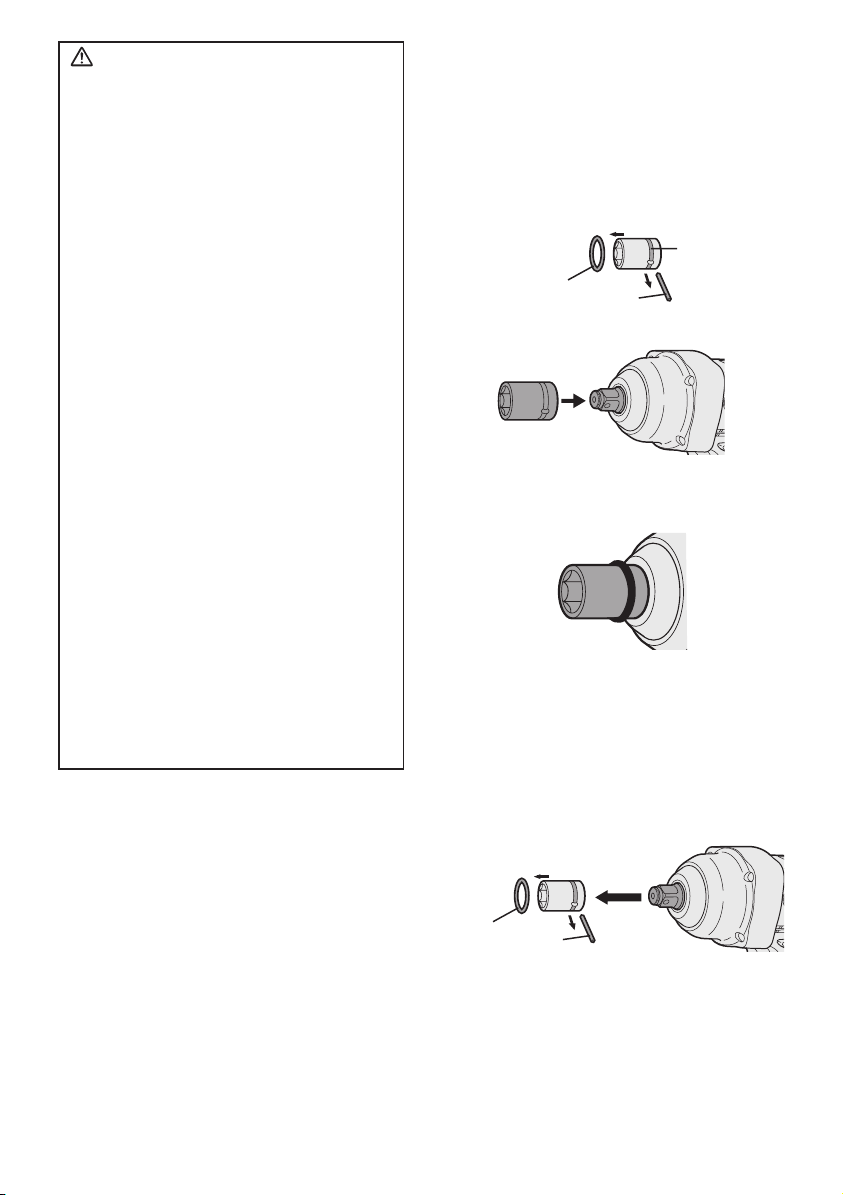
1. Attaching Socket
1) Remove the rubber ring and pin.
groove
rubber ring
pin
2) Attach the socket putting each holes.
3) Attach the rubber ring and pin in reverse
order of 1).
NOTE:
Attach socket firmly by using pin and
rubber ring.
Retainer ring is only for temporary
fixing.
2. Removing Socket
1) Remove the rubber ring and pin.
-
7 -
rubber
ring
pin
Page 8
Attaching or Removing
Bat tery Pack
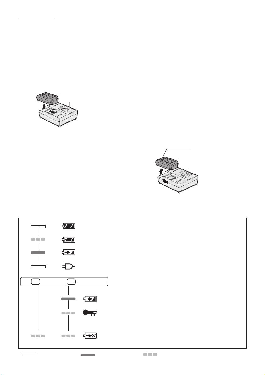
1. To connect the battery pack:
Align the highlighted marker points and
attach battery pack.
• Slide the battery pack until it locks into
position.
Alignment
marks
2. To remove the battery pack:
Push the button and slide the battery pack
forward.
V. OPERATION
WARNING!
• Do not inhale any smoke emitted from the
tool or battery pack as it may be harmful.
[Main unit]
Switch and Forward/
Reverse Lever Operation
Forward Reverse
Button
Switch lock
CAUTION:
To prevent damage, do not operate
Forward/Reverse lever until the socket
comes to a complete stop.
-
8 -
Page 9
Forward Rotation Switch
Operation
1. Push the lever for forward rotation.
2. Depress the trigger switch slightly to start
the tool slowly.
3. The speed increases with the amount
of depression of the trigger for efficient
tightening of bolts. The brake operates and
the socket stops immediately when the
trigger is released.
4. After use, set the lever to its center position
(switch lock).
Reverse Rotation Switch
Operation
1. Push the lever for reverse rotation. Check
the direction of rotation before use.
2. Depress the trigger switch slightly to start the
tool slowly.
3. After use, set the lever to its center position
(switch lock).
CAUTION:
• To eliminate excessive temperature
increase of the tool surface, do not
operate the tool continuously using two
or more battery packs. Tool needs cool
off time before switching to another pack.
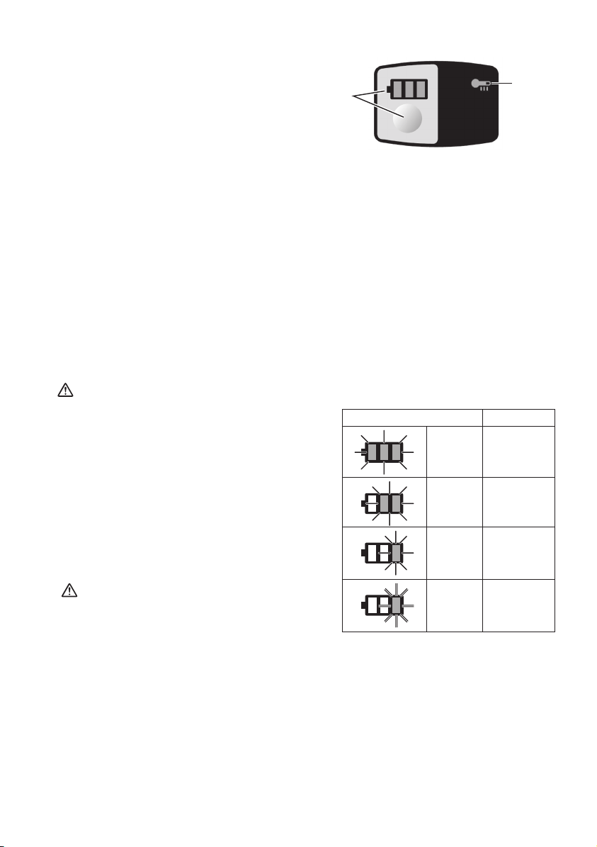
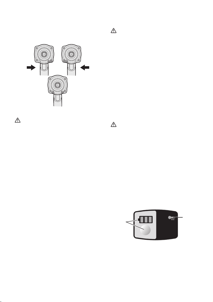
Indication panel
(1)
(1) Battery level indicator and button
• Press the battery level button.
Battery level indicator shows battery level
for approx. 10 seconds.
NOTE:
The indicator will not show the battery
level even the button is pushed in the
following cases.
• The main unit is powered off.
• Just after attaching the battery pack
• The main unit or battery level button is
not operated for approx. one minute.
Push the battery level button again after
depressing the trigger switch.
• The battery temperature is high.
Stop the operation and wait until the
battery temperature is low.
Indicator Battery status
3 lamps
illuminated
(2)
Charged
enough
Variable Speed Control
Trigger
To set the center of a hole, pull the trigger
slightly to start the socket rotation slowly.
The more the speed control trigger is
pulled, the higher the speed becomes.
CAUTION:
When operating the tool by depressing
the trigger, there may be a momentary lag
before rotation starts. This does not signal
a malfunction.
• This lag occurs as the tool’s circuitry
starts up when the trigger is pulled for
the first time after installing a new battery
pack or after the tool has not been
used for at least 1 minute. Rotation will
start without any lag during second and
subsequent operations.
-
2 lamps
illuminated
One lamp
illuminated
One lamp
ashing
Battery level indication is just guide.
The indication may change due to the
condition of battery or ambient temperature.
9 -
Approx. 50%
remaining
Battery level
is low.
Need to be
charged soon
Empty
Need to be
charged
immediately
Page 10
(2) Overheat warning lamp
[Battery Pack]
For Appropriate Use of
Bat tery Pack
Off
(normal
operation)
To protect the motor or battery, be sure to
note the following when carrying out this
operation.
• If the motor or battery becomes hot, the
protection function will be activated and
the motor or battery will stop operating.
The overheat warning lamp on the
indication panel illuminates or flashes
when this feature is active.
• If the overheating protection feature
activates, allow the tool to cool
thoroughly (at least 30 minutes). The
tool is ready for use when the overheat
warning lamp goes out.
• Avoid using the tool in a way that causes
the overheating protection feature to
activate repeatedly.
• If the tool is operated continuously under
high-load conditions or if it is used in hottemperature conditions (such as during
summer), the overheating protection
feature may activate frequently.
• If the tool is used in cold-temperature
conditions (such as during winter) or if
it is frequently stopped during use, the
overheating protection feature may not
activate.
Illuminated:
Overheat
(motor)
Indicates operation has
been halted due to motor
or battery overheating.
Flashing:
Overheat
(battery)
Recommended Grip
Use the grip to hold and operate the
driver with one hand. If the job requires
additional force, you can push against the
rear end of the driver with your other hand.
Li-ion Battery Pack
•
For optimum battery life, store the Li-ion
battery pack following use without charging it.
• When charging the battery pack, confirm
that the terminals on the battery charger
are free of foreign substances such as dust
and water etc. Clean the terminals before
charging the battery pack if any foreign
substances are found on the terminals.
The life of the battery pack terminals may be
affected by foreign substances such as dust
and water etc. during operation.
• When battery pack is not in use, keep it
away from other metal objects like: paper
clips, coins, keys, nails, screws, or other
small metal objects that can make a
connection from one terminal to another.
Shorting the battery terminals together
may cause sparks, burns or a fire.
• When operating the battery pack, make
sure the work place is well ventilated.
• When the battery pack is removed from the
main unit of the tool, replace the battery
pack cover immediately in order to prevent
dust or dirt from contaminating the battery
terminals and causing a short circuit.
Battery Pack Life
The rechargeable batteries have a
limited life. If the operation time becomes
extremely short after recharging, replace
the battery pack with a new one.
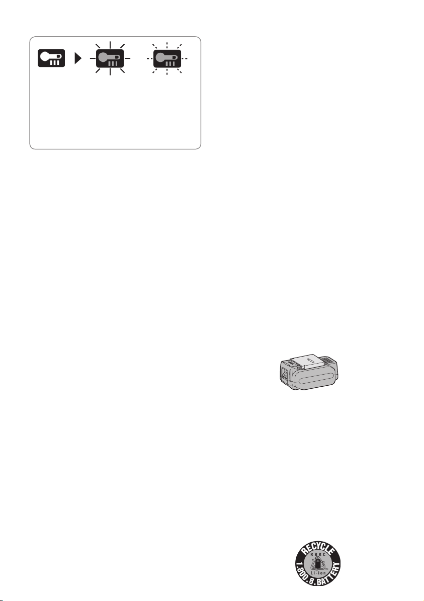
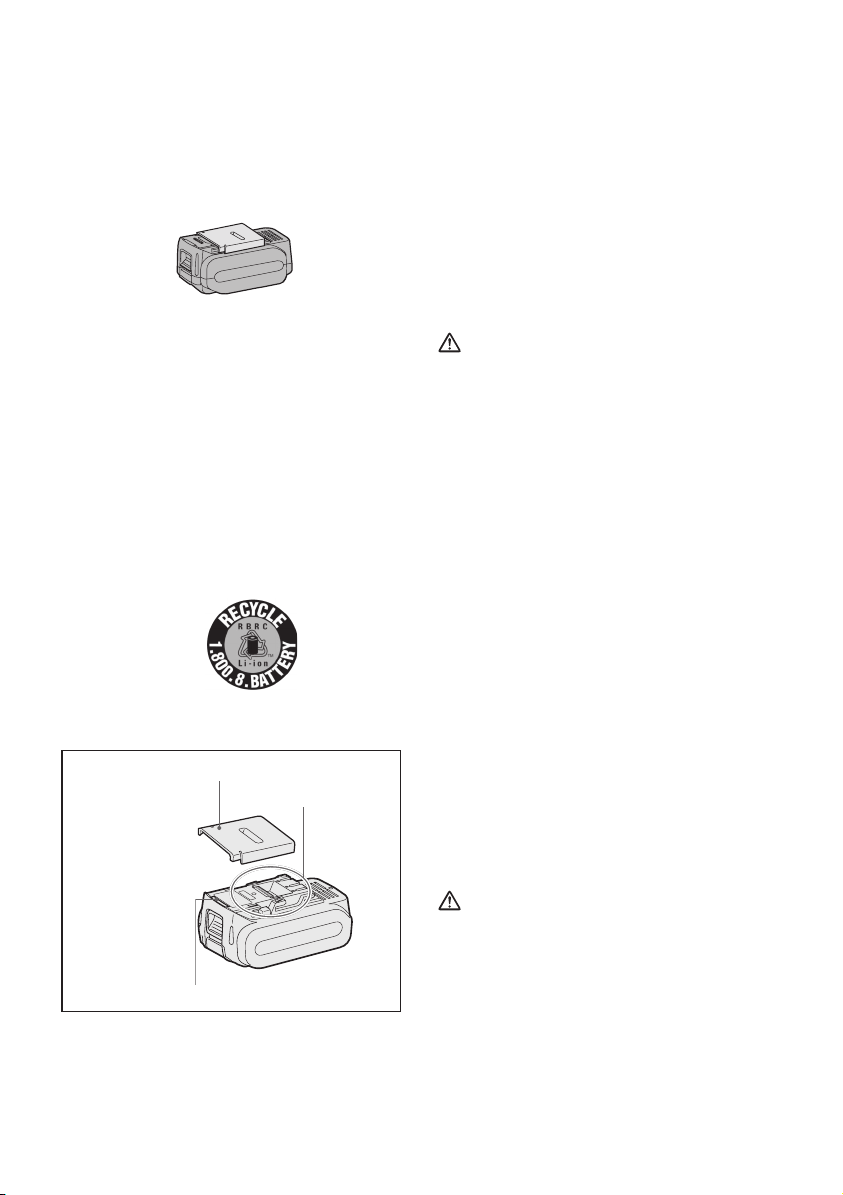
Battery Recycling
ATTENTION:
FOR Li-ion Battery Pack
A Li-ion battery that is recyclable powers
the product you have purchased. Please
call 1-800-8-BATTERY for information on
how to recycle this battery.
-
10 -
Page 11
Recommendations for use
Pack cover
Terminals
Label
Be sure to use the Pack cover
When the battery pack is not being used,
store the battery in a way that foreign
substances such as dust and water etc. do
not contaminate the terminals. Be sure to
attach the battery pack cover to protect the
battery terminals.
When charging the battery pack, conrm
that the terminals on the battery charger
are free of foreign substances such as
dust and water etc. Clean the terminals
before charging the battery pack if any
foreign substa nces a re fou nd on the
terminals.
The life of the battery pack terminals may be
affected by foreign substances such as dust
and water etc. during operation.
CAUTION:
To protect the motor or battery, be sure
to note the following when carrying out
operation.
If the motor and battery becomes hot, the
protection function will be activated and the
motor and battery will stop operating.
For safe use
The battery pack is designed to be installed
by proceeding two steps for safety. Make
sure the battery pack is installed properly to
the main unit before use.
If the battery pack is not connected rmly
when the switch is switched on, the overheat
warning lamp and the battery low warning
lamp will ash to indicate that safe operation
is not possible, and the main unit will not
rotate normally. Connect the battery pack
into the unit of the tool until the red or yellow
label disappears.
[Battery Charger]
Charging
CAUTION:
• The charger is designed to operate on
standard domestic electrical power only as
stated in the rating plate. Charge only on
the voltage indicated on the rating plate of
unit. e.g.230v / 50Hz.
• Do not attempt to use it on any other
voltage or frequency rating!
• If the temperature of the battery pack
falls approximately below −10°C (14°F),
charging will automatically stop to prevent
degradation of the battery.
• The ambient temperature range is
between 0°C (32°F) and 40°C (104°F).
If the battery pack is used when the battery
temperature is below 0°C (32°F), the tool
may fail to function properly.
• Use the charger at temperatures between
0°C and 40°C, and charge the battery at
a temperature similar to that of the battery
itself. (There should be no more than a
15°C difference between the temperatures
of the battery and the charging location.)
• When charging a cool battery pack (below
0°C (32°F)) in a warm place, leave the
battery pack at the place and wait for more
than one hour to warm up the battery to the
level of the ambient temperature.
• Cool down the charger when charging
more than two battery packs consecutively.
• Do not insert your fingers into contact
hole, when holding charger or any other
occasions.
CAUTION:
To prevent the risk of re or damage to the
battery charger.
• Do not cover vent holes on the charger and
the battery pack.
• Unplug the charger when not in use.
NOTE:
Your battery pack is not fully charged at
the time of purchase. Be sure to charge
the battery before use.
-
11 -
Page 12
How to charge
1. Plug the charger into the AC outlet.
NOTE:
Sparks may be produced when the plug
is inserted into the AC power supply, but
this is not a problem in terms of safety.
2. Connect the battery pack firmly into the
charger.
1 Line up the alignment marks and place
the battery onto the dock on the charger.
2 Slide forward in the direction of the arrow.
Alignment marks
3. During charging, the charging lamp will be
Illuminated.
When charging is completed, an internal
electronic switch will automatically be
triggered to prevent overcharging.
• Charging will not start if the battery pack
is warm (for example, immediately after
heavy-duty operation).
The orange standby lamp will be flashing
until the battery cools down.
Charging will then begin automatically.
4. The charge lamp (green) will flash slowly
once the battery is approximately 80%
charged.
5. When charging is completed, the charging
lamp in green color will turn off.
6. If the temperature of the batter pack is
0°C or less, charging takes longer to fully
charge the battery pack than the standard
charging time.
Even when the battery is fully charged,
it will have approximately 50% of the
power of a fully charged battery at normal
operating temperature.
7. Consult an authorized dealer if the charging
lamp (green) does not turn off.
8. If a fully charged battery pack is inserted
into the charger again, the charging
lamp lights up. After several minutes, the
charging lamp in green color will turn off.
9. Remove the battery pack while the battery
pack release button is held up.
Battery pack
release button
LAMP INDICATIONS
Charging is completed. (Full charge.)
Battery is approximately 80% charged.
Now charging.
Charger is plugged into the AC outlet. Ready to charge.
(Green) (Orange)
Turn off Illuminated Flashing
Charging Status Lamp.
Left: green Right: orange will be displayed.
Battery pack is cool.
The battery pack is being charged slowly to reduce the load on the battery.
Battery pack is warm.
Charging will begin when temperature of battery pack drops. If the temperature of the
battery pack is -10° or less, the charging status lamp (orange) will also start flashing .
Charging will begin when the temperature of the battery pack goes up"
Charging is not possible. Clogged with dust or malfunction of the battery pack.
-
12 -
Page 13
N・m
3.0
VI. MAINTENANCE
N・m
3.0
• Use only a dry, soft cloth for wiping the unit.
Do not use a damp cloth, thinner, benzine, or
other volatile solvents for cleaning.
• In the event that the inside of the tool or
battery pack is exposed to water, drain and
allow to dry as soon as possible. Carefully
remove any dust or iron filings that collect
inside the tool. If you experience any
problems operating the tool, consult with a
repair shop.
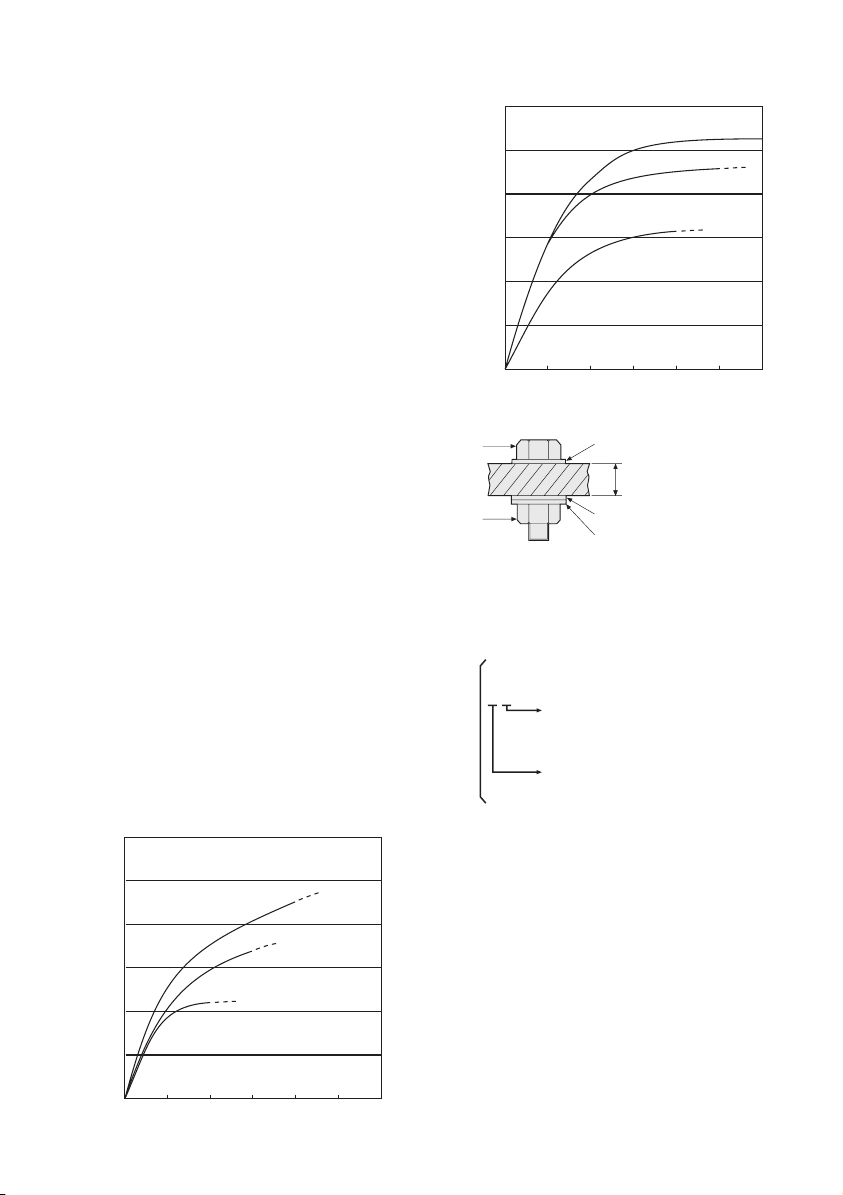
VII. TIGHTENING
TORQUE
The power required for tightening a bolt will
vary, according to bolt material and size, as
well as the material being bolted. Choose
the length of tightening time accordingly.
Reference values are provided below.
(They may vary according to tightening
conditions.)
Factors Affecting Tightening Torque
The tightening torque is affected by a wide
variety of factors including the followings.
After tightening, always check the torque
with a torque wrench.
1) Voltage
When the battery pack becomes nearly
discharged, the voltage decreases and the
tightening torque drops.
M16, M20, M24 x 45 mm
(㎏f-cm)
M16,M20,M24×45mm
600
(6122)
500
(5102)
400
(4082)
300
(3061)
200
Tightening torque
(2041)
100
(1020)
0.50.0 1.0 1.5 2.0 2.5
M24
M20
M16
Tightening time (Sec.)
Standard bolt
(㎏f-cm)
M16,M20,M24×45mm
600
(6122)
500
(5102)
400
(4082)
300
(3061)
200
Tightening torque
(2041)
100
(1020)
0.50.0 1.0 1.5 2.0 2.5
Tightening time (Sec.)
Bolt
Nut
Tightening conditions
• The following bolts are used.
Standard bolts: Strength type 4.8
High tensile type 12.9
Explanation of the strength type
4.8
Bolt yield point
(
80% of tensile strength)
32 kgf/mm
Bolt tensile strength
40 kgf/mm
2) Tightening time
Longer tightening time results in increased
tightening torque. Excessive tightening,
how ever, adds no value and reduces the
life of the tool.
3) Different bolt diameters
The size of the bolt diameter affects the
tight ening torque.
Generally, as the bolt diameter increases,
tightening torque rises.
4) Tightening conditions
• Tightening torque will vary, even with the
same bolt, according to grade, length, and
torque coefficient (the fixed coefficient indicated by the manufacturer upon production).
13 -
-
M16, M20, M24 x 45 mm
High tensile bolt
M24
M20
M16
Washer
Steel plate
thickness 10 mm
Washer
Spring washer
2
(45000 psi)
2
(56000 psi)
Page 14

• Tightening torque will vary, even with
the same bolting material (e.g. steel),
accord ing to the surface finish.
• Torque is greatly reduced when the bolt
and nut start turning together.
5) Socket play
Torque is lowered as the six-sided configu-
ration of the socket of the wrong size is
used to tighten a bolt.
6) Switch (Variable speed control trigger)
Torque is lowered if the unit is used with
the switch not fully depressed.
7) Effect of Connecting Adaptor
The tightening torque will be lowered
through the use of a universal joint or a
connecting adaptor.
VIII. ACCESSORIES
Use only suitable size of socket.
IX. APPENDIX
MAXIMUM RECOMMENDED CAPACITIES
Model
Bolt fastening
Standard bolt : M12 - M20
High tensile bolt : M12 - M18
EY7552
WARRANTY SUPPLEMENT
The breakdown and damage caused by usage consistent for a long time (e.g.: factory work on
the assembly line, etc.) is out of warranty.
X. SPECIFICATIONS
MAIN UNIT
Model
Motor voltage 18 V DC
No load speed 0 - 1550 min
Maximum torque 470 N·m
Impact per minute 0 - 2400 min
Overall length 214 mm
Weight
(with battery pack: EY9L50)
Weight
(with battery pack: EY9L51)
Noise,Vibration See the included sheet
EY7552
-1
-1
2.6 kg
-
14 -
Page 15

BATTERY PACK
Model EY9L50 EY9L51
Storage battery Li-ion Battery
Battery voltage 18 V DC (3.6 V x 10 cells)
BATTERY CHARGER
Model EY0L81
Electrical rating See the rating plate on the bottom of the charger
Weight 0.93 kg
EY9L50 EY9L51
Charging time
Model EY0L82
Electrical rating See the rating plate on the bottom of the charger
Weight 0.93 kg
Charging time
NOTE: This chart may include models that are not available in your area.
Please refer to the latest general catalogue.
NOTE: For the dealer name and address, please see the included warranty card.
Usable: 50 min Usable: 65 min
Full: 65 min Full: 80 min
EY9L50 EY9L51
Usable: 40 min Usable: 55 min
Full: 55 min Full: 70 min
-
15 -
Page 16

Federal Communication Commission Interference Statement
This equipment has been tested and found to comply with the limits for a Class B digital
device, pursuant to Part 15 of the FCC Rules. These limits are designed to provide reasonable
protection against harmful interference in a residential installation. This equipment generates,
uses and can radiate radio frequency energy and, if not installed and used in accordance with
the instructions, may cause harmful interference to radio communications. However, there is
no guarantee that interference will not occur in a particular installation. If this equipment does
cause harmful interference to radio or television reception, which can be determined by turning
the equipment off and on, the user is encouraged to try to correct the interference by one of
the following measures:
• Reorient or relocate the receiving antenna.
• Increase the separation between the equipment and receiver.
• Connect the equipment into an outlet on a circuit different from that to which the receiver is
connected.
• Consult the dealer or an experienced radio/TV technician for help.
FCC Caution: To assure continued compliance, install and use in accordance with provided
instructions. Use only the battery pack specified in the instructions. Any changes or
modifications not expressly approved by the party responsible for compliance could void the
user’s authority to operate this equipment.
This device complies with part 15 of the FCC Rules. Operation is subject to the following two
conditions: (1) This device may not cause harmful interference, and (2) this device must accept
any interference received, including interference that may cause undesired operation.
This Class B digital apparatus complies with Canadian ICES-003.
-
16 -
Page 17

Cet outil, en tant qu'unité complète avec sa
batterie autonome, répond aux Degrés de
Protection IP appropriés selon les normes IEC.
Définitions des codes IP
IP5X: L’entrée de poussière n’est pas
complètement empêchée maisl a poussière
ne doit pas pénétrer au point de perturber le
fonctionnement satisfaisant de l’outil ou d’en
affecter la sécurité (Au cas où de la poudre
de talc de moins de 75 μm s’introduirait à
l’intérieur de l’outil).
IPX6: L’eau projetée en jets puissants
contre l’outil de n’importe quelle direction
ne doit pas avoir d’effets nuisibles (Au cas
où approximativement 100 L/min d’eau à
température normale est projetée sur l’outil a
3 mètre de distance pendant 3 minutes avec
une lance de 12,5 mm de diamètre intérieur).
GARANTIE LIMITÉE
Le code IP56 rend possible un impact
minimum d’eau et de poussière sur cet outil
mais il n’en garantit pas les performances
dans de telles conditions. Veuillez lire la
notice d’utilisation et de sécurité pour plus de
détails quant à un fonctionnement approprié.
I. CONSIGNES
DE SECURITE
GENERALES
AVERTISSEMENT! Veuillez lire
toutes les instructions.
Si les instructions détaillées ci-dessous
ne sont pas observées, cela peut
entraîner une électrocution, un incendie
et/ou des blessures graves. Le terme
“outil mécanique” utilisé dans tous les
avertissements ci-dessous se réfère aux
outils mécaniques opérés par cordons
d'alimentation et par batterie (sans l).
CONSERVEZ CES INSTRUCTIONS
Sécurité de la zone de travail
1) Gardez la zone de travail propre et bien
aérée.
Les endroits encombrés et sombres invitent
les accidents.
2) Ne faites pas fonctionner les outils
mécaniques dans des atmosphères
explosives, comme en présence de
liquides inflammables, de gaz ou de
poussière.
Les outils mécaniques génèrent des étincelles
qui peuvent enflammer la poussière ou les
vapeurs.
3) Gardez les enfants et les spectateurs
éloignés lors du fonctionnement d’un
outil mécanique.
Les distractions peuvent en faire perdre le
contrôle.
Sécurité électrique
1) La fiche des outils mécaniques doit
correspondre aux prises secteur.
Nemodifiez la fiche sous aucun prétexte.
N’utilisez pas de fiche adaptatrice avec
les outils mécaniques mis à la terre.
Des fiches non modifiées et des prises
secteur correspondant réduisent les risques
d’électrocution.
2) Evitez tout contact physique avec les
surfaces mises à la terre telles que tuyaux,
radiateurs, micro-ondes et réfrigérateurs.
Il y a un risque d’électrocution supplémentaire
si votre corps est mis à la terre.
3) N’exposez pas les outils mécaniques à la
pluie ou à des conditions humides.
De l’eau pénétrant dans un outil mécanique
augmente le risque d’électrocution.
4) Ne malmenez pas le cordon. N’utilisez
jamais le cordon pour transporter,
pour tirer ou pour débrancher l’outil
mécanique. Gardez le cordon éloigné de
la chaleur, de l’huile, d’objets aux bords
coupants ou de pièces en mouvement.
Les cordons endommagés on emmêlés
augmentent le risque d’électrocution.
5) Lors du fonctionnement des outils
mécaniques à l’extérieur, utilisez une
rallonge adaptée à l’utilisation à l’extérieur.
L’utilisation d’un cordon adapté à l’utilisation à
l’extérieur réduit les risques d’électrocution.
6) Si le fonctionnement d’un outil mécanique
dans un endroit humide est inévitable,
utilisez une alimentation électrique pour
dispositif protégé contre le courant
résiduel (RC D).
L’utilisation d’un RCD réduit les risques
d’électrocution.
Sécurité personnelle
1) Restez alerte, regardez ce que vous faites
et faites preuve de bon sens lorsque vous
utilisez un outil mécanique. N’utilisez
-
17 -
Page 18

pas un outil mécanique alors que vous
êtes fatigué ou sous les effets de drogue,
d’alcool ou de médicaments.
Un moment d’inattention pendant que vous
faites fonctionner l’outil mécanique peut
entraîner des blessures graves.
2) Utilisez des équipements de sécurité.
Portez toujours des protection pour vos
yeux.
Des équipements de sécurité comme
masque antipoussière, chaussures de
sécurité non glissantes, casque de protection
ou protections d’oreilles, utilisés dans
des conditions appropriées réduisent les
blessures corporelles.
3) Evitez tout démarrage accidentel.
Assurez-vous que l’interrupteur est en
position d’arrêt avant de brancher l’outil.
Le transport d’outils mécaniques avec le
doigt sur l’interrupteur ou le branchement
d’outils mécaniques dont l’interrupteur est sur
la position de marche invite les accidents.
4) Ne vous mettez pas en déséquilibre.
Gardez une bonne prise au sol et votre
équilibre à tout moment.
Ceci permet un meilleur contrôle de l’outil
mécanique dans des situations inattendues.
5) Habillez-vous correctement. Ne portez
pas de vêtements lâches ou de bijoux.
Gardez vos cheveux, vêtements et gants
éloignés des pièces en mouvement.
Des vêtements lâches, des bijoux ou des
cheveux longs peuvent se faire prendre dans
les pièces en mouvement.
6) Si des dispositifs pour la connexion d’ap
pareils d’extraction et de ramassage de
la poussière sont fournis, assurez-vous
qu’ils sont connectés et correctement
utilisés.
L’utilisation de ces dispositifs peut réduire les
risques concernés.
Utilisation et soins de l’outil
méca nique
1) Ne forcez pas l’outil mécanique. Utilisez
l’outil mécanique correct pour votre
application.
L’outil mécanique correct exécute mieux
le travail dans de meilleurs conditions de
sécurité s’il est utilisé à l’allure pour laquelle il
a été conçu.
2) N’utilisez pas l’outil mécanique si
l’interrupteur ne le met pas en marche ou
ne l’arrête pas.
Tout outil mécanique qui ne peut pas être
contrôlé par son interrupteur est dangereux
et doit être réparé.
3) Débranchez la fiche de la source
d’alimentation et/ou du bloc d e
batterieavant d’effectuer tout ajustement,
de changer d’accessoire ou de ranger
l’outil mécanique.
De telles mesures de sécurité préventives
réduisent les risques de faire démarrer l’outil
mécanique accidentellement.
4) Rangez les outils mécaniques inutilisés
hors de la portée des enfantset ne laissez
personne qui n’est pas familiarisé avec
l’outil mécanique ou ses instructions faire
fonctionner l’outil mécanique.
Les outils mécaniques sont dangereux
dans les mains des utilisateurs manquant
d’entraînement.
5) Entretenez bien les outils mécaniques.
Vérifiez l’alignement ou l’emboîtage
des pièces en mouvement, l’intégrité
des pièces et toute autre condition
pouvant affecter le fonctionnement de
l’outil mécanique. S’il est endommagé,
faites réparer l’outil mécanique avant de
l’utiliser.
De nombreux accidents sont provoqués par
des outils mécaniques mal entretenus.
6) Maintenez les outils de coupe affûtés et
propres.
Les outils de coupe bien entretenus avec des
lames bien affûtées ont moins de chances de
gripper et sont plus faciles à contrôler.
7) Utilisez l’outil mécanique, les accessoires,
les mèches, etc., conformément à ces
instructions et de la façon pour laquelle
l’outil particulier a été conçu en tenant
compte des conditions de travail et de la
tâche à exécuter.
L’utilisation de l’outil mécanique à des fins
autres que celles pour lesquelles ila été
conçu peut présenter une situation à risque.
Utilisation et soins de la
batterie de l’outil
1) Assurez-vous que l’interrupteur est dans
la position d’arrêt avant d’insérer le bloc
de batterie.
L’insertion du bloc de batterie dans un
outil mécanique dont l’interrupteur est sur
la position de marche peut provoquer des
accidents.
-
18 -
Page 19

2) N’effectuez la recharge qu’avec le
chargeur spécifié par le fabricant.
Un chargeur convenant à un bloc de batterie
peut entraîner un risque d’incendie lorsqu’un
autre bloc de batterie est utilisé.
3) N’utilisez les outils mécaniques qu’avec
les bloc de batterie spécialement conçus
pour eux.
L’utilisation de tout autre bloc de batterie peut
entraîner un risque de blessure et d’incendie.
4) Lorsqu’un bloc de batterie n’est pas
utilisé, gardez-le éloigné d’objets
métalliques comme agrafes, pièces de
monnaie, clés, clous, vis ou tout autre
petit objet métallique pouvant établir une
connexion entre les deux bornes.
Si les bornes de la batterie sont mises en
court-circuit, cela peut entraîner des brûlures
ou un incendie.
5)
Si elle est malmenée, du liquide peut
s’échapper de la batterie. Evitez tout
contact. Si un contact accidentel se produit,
rincez à l’eau. Si du liquideentre en contact
avec les yeux, consultez un médecin.
Le liquide éjecté de la batterie peut entraîner
des irritations ou des brûlures.
Réparation
1) Faites réparer votre outil mécanique par
du personnel de réparation qualifié en
n’utilisant que des pièces de rechange
identiques.
Ceci assure le maintien de la sécurité de
l’outil mécanique.
II. REGLES DE
SECURITE
PARTICULIERES
Le contact avec un fil sous tension fera
passer le courant dans les pièces métalliques
exposées et électrocutera l’opérateur.
4) Si la douille est coincée, mettez
immédiatement le commutateur de la
gâchette hors tension afin de prévenir une
surcharge pouvant endommager la batterie
autonome ou le moteur. Dégagez la douille
en inversant le sens de rotation.
5) NE manoeuvrez PAS le levier d’inversion
marche avant - marche arrière lorsque le
commutateur principal est sur la position
de marche. La batterie se déchargerait
rapidem ent et la perce use serait
endommagée.
6) Lorsque vous rangez ou transportez l’outil,
mettez le levier d’inversion marche avant -
marche arrière sur la position centrale
(verrouillage du commutateur).
7) Ne forcez pas l’outil en maintenant la gâchette
de contrôle de vitesse enfon cée à moitié
(mode de contrôle de la vitesse) de sorte que
le moteur s’arrête. Le circuit de protection
s’activera et pourra empêcher le contrôle de
la vitesse. Dans ce cas, relâchez la gâchette
de contrôlede la vitesse, puis serrez-la à
nouveau pour le fonc tionnement normal.
8) Evitez la pénétration de poussière dans le
mandrin.
9) Ne touchez pas les pièces rotatives pour
éviter toute blessure.
10) N’utilisez pas l’outil continuellement pendant
une longue période. Arrêtez d’utiliser l’outil de
temps en temps pour éviter une augmentation
de la température et de surchauffer le moteur.
11) Ne laissez pas tomber l’outil.
Symbole Signication
V
Volts
1) Portez des lunettes lorsque vous utilisez
l’outil pendant de longues périodes.
L’exposition prolongée à du bruit de haute
densité peut entraîner la perte de l’ouïe.
2) N’oubliez pas que cet appareil est toujours
prêt à fonctionner, parce qu’il ne doit pas être
branché dans une prise électrique.
3) Tenez l’outil par les surfaces de prise
isolées lorsque vous effectuez une
opération lors de laquelle l’outil decoupe
risque d’entrer en contact avec des
câblages cachés.
-
19 -
n
0
… min
Ah
Courant continu
Vitesse sans charge
Tours ou mouvements
-1
alternatifs par minute
Capacité électrique de la
batterie autonome
An de réduire le risque de
blessure, il est nécessaire
que l’utilisateur lise et
comprenne lemode d’emploi.
Page 20

AVERTISSEMENT!
La poussière résultant de ponçage, sciage,
meulage, perçage à haute pression et
de toute autre activité de construction,
contient des produits chimiques réputés
être causede cancer, de malformations
congénita l e s ou a ut r e s pr o b l èm e s
reproductifs. Ces produits chimiques sont,
par exemple :
• Le plomb contenu dans les peintures à
base de plomb
• La silice cristalline, contenue dans les
briques, le ciment et autres produits de
maçonnerie; et
• L’arsenic et le chrome provenant du bois
traité chimiquement.
Pour réduire l’exposition à ces produits
chimiques, il faut travailler dans un lieu
bienaéré et porter un équipement de
sécurité approprié tel que certains masques
antipoussière conçus spécialement pour
ltrer les particules microscopiques.
III. CHARGEUR DE
BATTERIE ET
BATTERIE AUTO
NOME
In st ru ct ions de sécurité
importantes
1) CONSERVEZ CES INSTRUCTIONS -
La présente notice contient des instructions
de sécurité et d’utilisation importantes pour le
chargeur de batterie.
2) Avant d’utiliser le chargeur de batterie,
lisez toutes les instructions et les marques
d’avertissement figurant sur le chargeur de
batterie, la batterie autonome et le produit
utilisant la batterie autonome.
3) MISE EN GARDE -Pour réduire le risque
de blessures, chargez la batterie autonome
Panasonic seulement comme indiqué à la
dernière page.
Les autres types de batteries risquent
d’exploser et de causer des blessures
corporelles et des dommages matériels.
4) N’exposez pas le chargeur à la pluie ou à la
neige.
5) Pour réduire les risques de dommages à la
fiche et au cordon secteur, débranchez le
chargeur en tirant la fiche et non le cordon.
6) Veillez à acheminer le cordon de façon
que personne ne risque de le piétiner, de
trébucher dessus, d’endommager ou d’étirer
le cordon.
7) N’utilisez une rallonge qu’en cas de nécessité
absolue.
Si vous utilisez une rallonge inadéquate, vous
risquez de causer un incendie ou une électrocution.
Si vous devez absolument utiliser une rallonge,
veillez à respecter les points suivants:
a. Le nombre, la taille et la forme des broches
de la fiche de la rallonge doivent être
identiques à ceux de la fiche du chargeur
de batterie.
b. La rallonge doit avoir des conducteurs en
bon état et être elle-même en bon état
d’utilisation.
c. La taille des conducteurs doit être suffisante
pour les normes d’intensité en ampères du
chargeur, comme indiqué ci-dessous.
TAILLE AWG MINIMUM RECOMMANDÉE DES
RALLONGES POUR CHARGEURS
Norme d’entrée CAAmpères
Egal ou
supérieur à
0 2 18 18 18 16
8) N’utilisez pas un chargeur dont la fiche ou
le cordon est endommagé – remplacez-les
immédiatement.
9) N’utilisez pas le chargeur s’il a reçu un choc
violent, s’il a subi une chute ou s’il a été
endommagé de quelque manière que ce soit;
confiez-le à un technicien qualifié.
10) Ne démontez pas le chargeur; si des travaux
d’entretien ou de réparation sont nécessaires,
confiez-le à un technicien qualifié. Si vous le
remontez incorrectement, vous risquez de
causer une électrocution ou un incendie.
11) Pour réduire le risque d’électrocution,
débranchez le chargeur de la prise de courant
avant d’entreprendre des travaux d’entretien
ou de nettoyage.
12) Le chargeur et la batterie autonome ont été
conçus spécifiquement pour fonctionner
ensemble.
DE BATTERIES
Mais
inférieur à
Taille AWG du
cordon
Longueur du
cordon, pieds
25 50 100 150
-
20 -
Page 21

Ne tentez pas de charger un autre outil
àbatterie ou une autre batterie autonome
avec ce chargeur.
13) Ne tentez pas de charger la batterie
autonome avec un autre chargeur.
14) Ne tentez pas de démonter le logement de la
batterie autonome.
15) Ne rangez pas l’outil ou la batterie autonome
à des endroits où la température est
susceptible d’atteindre ou de dépasser 50°C
(122°F) (par exemple dans une remise
d’outils électriques, ou dans une voiture en
été), car ceci risquerait d’abîmer la batterie
stockée.
16) Ne chargez pas la batterie autonome lorsque
la température est INFÉRIEUREÀ 0°C (32°F)
ou SUPÉRIEURE à 40°C(104°F). Ceci est
très important pour conserver le bon état de
fonctionnement de la batterie autonome.
17) N’incinérez pas la batterie autonome. Elle
risquerait d’exploser dans les flammes.
18) Evitez toute utilisation dans un environnement
dangereux. N’utilisez pas le chargeur à un
endroit humide ou mouillé.
19) Le chargeur a été conçu pour fonctionner
uniquement sur des prises secteur
domestiques standard. Ne l’utilisez passous
des tensions différentes!
20) Ne manipulez pas brutalement le cordon
secteur. Ne transportez jamais le chargeur
en le tenant par le cordon, ou ne le tirez pas
brutalement pour le débrancher de la prise.
Gardez le cordon à l’abri de la chaleur, de
l’huile et de bords coupants.
21) Chargez la batterie autonome à un endroit
bien ventilé; ne couvrez pas le chargeur et
la batterie autonome avec un chiffon, etc.,
pendant la charge.
22) Si vous utilisez un accessoire non
recommandé, un incendie, une électrocution,
des blessures risqueraient de s’ensuivre.
23) Ne court-circuitez pas la batterie autonome.
Un court-circuit de la batterie risquerait de
faire passer un courant deforte intensité, et
une surchauffe, un incendie ou des blessures
risqueraient de s’ensuivre.
24) REMARQUE: Si le cordon secteur de cet
appareil est endommagé, il doit être remplacé
exclusivement dans un atelier agréé par le
fabricant, car ces travaux exigent l’utilisation
d’outils spéciaux.
25) POUR RÉ D U I RE LES RISQUES
D’ÉLECTROCUTION, CET APPAREIL EST
ÉQUIPÉ D’UNE FICHE POLARI-SÉE (UNE
LAME EST PLUS LARGE QUE L’AUTRE).
Cette fiche ne pourra être insérée que d’une
seule façon dans une prise polarisée. Si la
fiche ne peut pas être insérée à fond dans la
prise, insérez lafiche sens dessus dessous.
Si vous ne parvenez toujours pas à insérer la
fiche, adressez-vous à un électricien qualifié
pour installer une prise de courant adéquate.
Ne modifiez la fiche en aucune façon.
AVERTISSEMENT:
• N’utilisez que la batterie autonome
Panasonic conçue pour l’utilisation avec cet
outil rechargeable.
• Panasonic décline toute responsabilité
en cas de dommage ou d’accident causé
par l’utilisation d’une batterie autonome
recyclée et d’une batterie autonome de
contrefaçon.
• Ne mettez pas la batterie autonome au
rebut dans un feu ou ne l’exposez pas à
une chaleur excessive.
• N’enfoncez pas de clous ou autres dans
la batterie autonome, ne la soumettez
pas à des chocs, ne la démontez pas ou
n’essayez pas de la modifier.
• Ne laissez pas d’objets métalliques entrer
en contact avec les bornes de la batterie
autonome.
• Ne transportez pas ou ne rangez pasla
batterie autonome dans un récipient
contenant des clous ou tout autre objet
métallique.
• Ne chargez pas la batterie autonome dans
un endroit où la température est élevée
comme à proximité d’un feu ou à la lumière
directe du soleil. Sinon la batterie peut
surchauffer, prendre feu ou exploser.
• N’utilisez que le chargeur dédié pour
charger la batterie autonome. Sinon, la
batterie peut fuir, surchauffer ou exploser.
-
21 -
Page 22

• Après avoir retiré la batterie autonome de
l’outil ou du chargeur, remettez toujours le
couverclede la batterie autonome en place.
Sinon, les contacts de la batteriepeuvent se
mettre en court-circuit, entraînant le risque
d’un incendie.
• Si la batterie autonome s’est détériorée,
la remplacer par une batterie neuve.
L’utilisation prolongée d’une batterie
autonome endommagée peut provoquer
des dégagements de chaleur, un départ de
feu ou l’explosion de la batterie.
IV. MONTAGE
Fixation ou retrait de la douille
1. Fixation de la douille
1) Retirez la bague en caoutchouc et la
goupille
Bague en
caoutchouc
Goupille
2) Fixez la douille en l’alignant avec chaque
orifice
Encoche
2. Retrait de la douille
1) Retirez la bague en caoutchouc et la
goupille.
Bague en
caoutchouc
Goupille
Fixation ou retrait de la
bat terie autonome
1. Pour raccorder la batterie autonome:
Alignez les marques d'alignement mises en
valeur et fixez la batterie autonome.
• Faites glisser la batterie autonome jusqu’à ce qu’elle se verrouille en position.
Marques
d’alignement
2. Pour retirer la batterie autonome:
Appuyez sur le bouton et faites glisser la
batterie autonome vers l’avant.
3) Fixez la bague en caoutchouc et la
goupille en suivant la séquence 1) dans
l’ordre inverse.
REMARQUE:
Fixez fermement la douille à l’aide de la
goupille et de la bague en caoutchouc.
La bague de retenue doit uniquement
être utilisée pour une fixation temporaire.
-
Button
V. FONCTIONNEMENT
AVERTISSEMENT!
•
Ne respirez pas la fumée dégagée par l’outil
ou la batterie, car elle pourrait être nocive.
22 -
Page 23
[Unité principale]
Utilisation du commutateur et
du levier d’inversion marche
avant-marche arrière
Rotation en
sens normal
Verrouillage du
commutateur
MISE EN GARDE:
Pour prévenir tout dégât, n’actionnez
pas le levier d’inversion marche avantmarche arrière tant que la douille n’a pas
complètement terminé de tourner.
Rotation en
sens inverse
Utilisation du commutateur
pour une rotation en sens
normal
1. Poussez le levier pour obtenir une rota tion
en sens normal.
2. Appuyez légèrement sur la gâchette pour
que l’outil commence à tourner lentement.
3. La vitesse augmente à mesure où la
gâchette est enfoncée pour un vissage
efficace des boulons. Le frein fonctionne et
la douille s’arrête immédiatement dès que
la gâchette est relâchée.
4. Ramenez le levier en position centrale
lorsque vous n’utilisez plus l’outil (ver rouillage du commutateur).
3. Ramenez le levier en position centrale
lorsque vous n’utilisez plus l’outil (verrouillage du commutateur).
MISE EN GARDE:
• Pour empêcher toute élévation excessive de la température de la surface
de l’outil, n’utilisez pas l’outil de façon
continue en utilisant deux batteries
autonomes ou plus. L’outil a besoin de
se refroidir pendant un certain temps
avant d’être connecté à une autre
batterie autonome.
Gâchette de commande
de vitesse
Pour ajuster le centre du trou, tirez
légèrement sur la gâchette pour démarrer
lentement la rotation de douille.
Plus vous appuyez sur la gâchette de
contrôle de vitesse, plus la vitesse est
grande.
MISE EN GARDE:
Lorsque vous faites fonctionner l’outil en
appuyant sur la gâchette, il peut y avoir un
décalage momentané avant le début de la
rotation. Cela ne signifie pas qu’il y a un
dysfonctionnement.
• Ce décalage se produit alors que les
circuits de l’outil sont activés quand on
appuie sur la gâchette pour la première
fois après l’installation d’un nouveau
bloc batterie ou après que l’outil n’a pas
été utilisé pendant au moins 1 minute.
La rotation démarrera sans décalage
lors du second fonctionnement et des
suivants.
Panneau indicateur
(2)
(1)
Utilisation du commutateur
de rotation en sens inverse
1. Poussez le levier pour obtenir une rotation
en sens inverse. Avant d’utiliser l’outil,
vérifiez le sens de rotation.
2. Appuyez légèrement sur la gâchette pour
que l’outil commence à tourner lentement.
-
23 -
(1)
Indicateur et bouton du niveau de la batterie.
•
Appuyez sur le bouton du niveau de la batterie.
Le niveau de la batterie s’affiche pendant
environ 10 secondes sur l’indicateur du
niveau de la batterie.
REMARQUE:
L’indicateur n’affiche pas le niveau de la
batterie, même si le bouton est enfoncé,
dans les cas suivants :
Page 24

• L’unité principale est en position off.
Juste après la fixation de la batterie autonome
•
• Lorsque l’unité principale ou le bouton
du niveau de la batterie ne sont pas
utilisés pendant environ une minute.
Poussez à nouveau sur le bouton du
niveau de la batterie après avoir appuyé
sur commutateur de la gâchette.
• La température de la batterie est élevée.
Arrêtez toute utilisation et attendez que
la température de la batterie ait diminué.
Indicateur
3 voyants
allumés
2 voyants
allumés
Un voyant
allumé
Un voyant
clignotant
Statut de la
batterie
Sufsamment
chargée
Environ 50 %
restants
Niveau de la
batterie faible
Doit être
bientôt
chargée
Vide
Doit être
chargée
immédiatement
L’indication du niveau de la batterie a une
valeur de guide uniquement.
Elle peut varier en fonction de l’état de la
batterie ou de la température ambiante.
(3) Témoin d’avertissement de surchauffe
Arrêt
Off
(fonction-
(normal
nement
normal)
operation)
Allumé:
Illuminated:
Surchauffe
Overheat
(moteur)
(motor)
Indique que le fonctionnement
Indicates operation has
a été arrêté à la suite d’une
surchauffe du moteur ou de la
been halted due to motor
batterie.
or battery overheating.
Clignotant:
Flashing:
Surchauffe
Overheat
(batterie)
(battery)
Pour protéger le moteur ou la batterie,
veillez à bien noter les points suivants
lorsque vous effectuez cette opération.
• Si le moteur ou la batterie deviennent
chauds, la fonction de protection sera
activée et le moteur ou la batterie
cesseront de fonctionner. Le témoin
d’avertissement de surchauffe sur le
panneau indicateur s’allume ou clignote
lorsque cette fonctionnalité est active.
• Si la caractéristique de protection contre
la surchauffe s’active, laissez l’outil se
refroidir complètement (au moins 30
minutes). L’outil est prêt à être utilisé
lorsque le témoin d’avertissement de
surchauffe s’éteint.
Evitez d’utiliser l’outil d’une façon qui
•
activerait de façon répétée la caractéristique
de protection contre la surchauffe.
• Si l’outil est utilisé de façon continue
sous haute charge, ou s’il est utilisé
dans un environnement chaud (en été
par exemple), il est possible que la
caractéristique de protection contre la
surchauffe s’active fréquemment.
• Si l’outil est utilisé dans un environnement
froid (en hiver par exemple), ou s’il est
arrêté fréquemment pendant l’utilisation,
il est possible que la caractéristique
de protection contre la surchauffe ne
s’active pas.
Recommandation pour la
prise en main
Utilisez la poignée pour tenir la perceuse t
l’utiliser d’une main. Si la tâche nécessite
plus de force, vous pouvez pousser
l’arrière de la perceuse de l’autre main.
[Batterie]
Pour une utilisation correcte
de la batterie autonome
Batterie autonome Li-ion
• Pour une longévité optimale de la batterie,
rangez la batterie autonome Li-ion sans la
charger après l’avoir utilisée.
• Lors de la charge de la batterie autonome,
assurez-vous que les bornes du chargeur
de batterie sont libres de tout corps étranger
comme de la poussière et de l’eau, etc.
Nettoyez les bornes avant de charger la batterie
autonome si des corps étrangers se trouvent
sur les bornes.
La durée de vie des bornes de la batterie
autonome peut être affectée par des corps
étrangers comme de la poussière et de l’eau,
etc. pendant le fonctionnement.
• Lorsque vous n’utilisez pas la batterie autonome,
éloignez-la d’autres objets métalliques tels que :
trombones, pièces de monnaie, clés, clous, vis
et autres petits objets métalliques susceptibles
de connecter les bornes entre elles.
Si vous court-circuitez les bornes de la batterie,
vous risquez de causer des étincelles, de vous
-
24 -
brûler ou de provoquer un incendie.
Page 25
• Lors de l’utilisation de la batterie autonome,
assurez-vous de la bonne ventilation du lieu de
travail.
• Lorsque la batterie autonome est retirée
de l’unité principale de l’outil, replacez
immédiatement le couvercle de la batterie
autonome afin d’empêcher la poussière ou la
crasse de contaminer les bornes de la batterie
et de provoquer un court-circuit.
Longévité des batteries autonomes
Les batteries rechargeables ont une
longévité limitée. Si le temps de fonction nement devient très court après la
recharge, remplacez la batterie auto nome
par une neuve.
Recyclage de la batterie autonome
ATTENTION:
Pour une batterie autonome Li-ion
La batterie Li-ion que vous vous êtesprocurée
est recyclable. Pour desrenseignements
sur le recyclagede la batterie, veuillez
composer le1-800-8-BATTERY.
Recommandations concernant
l’utilisation
Couvercle de la batterie autonome
Bornes
étranger comme de la poussière et de l’eau
ne contamine les bornes. Veillez à xer le
couvercle de la batterie autonome an de
protéger les bornes de la batterie.
Lors de la charge de la batterie autonome,
assurez-vous que les bornes du chargeur
de batterie sont libres de tout corps étranger
comme de la poussière et de l’eau, etc.
Nettoyez les bornes avant de charger la
batterie autonome si des corps étrangers se
trouvent sur les bornes.
La durée de vie des bornes de la batterie
autonome peut être affectée par des corps
étrangers comme de la poussière et de l’eau,
etc. pendant le fonctionnement.
MISE EN GARDE:
Pour protéger le moteur ou la batterie,
veillez à bien noter les points suivants
lorsque vous utilisez la machine.
Si le moteur et la batterie deviennent chauds,
la fonction de protection sera activée et le
moteur et la batterie cesseront de fonctionner.
Pour un usage sans risque
La batterie est conçue pour être installée en
deux étapes pour des raisons de sécurité.
Assurez-vous que la batterie est installée
correctement dans l’unité principale avant
toute utilisation.
Lorsque la batterie autonome n’est pas
connectée fermement à la mise sous
tension, le témoin d’avertissement de
surchauffe et le témoin d’avertissement
de faible batterie clignotent pour indiquer
qu’un fonctionnement sans danger n’est
pas possible et l’unité principale ne tourne
pas normalement. Branchez la batterie
autonome dans l’unité de l’outil jusqu’à ce
que l’indicateur rouge ou jaune disparaisse.
rouge
Veillez à utiliser le couvercle de la
batterie autonome
Lorsque le c o u ve r c l e d e l a b at t e r ie
autonome n’est pas utilisé, rangez la
batterie de façon à ce qu’aucun corps
-
[Chargeur de batterie]
Recharge
MISE EN GARDE:
• Le chargeur est conçu pour fonctionner
uniquement sur une prise électrique
domestique standard conformément aux
indications de la plaque signalétique. Le
chargement doit uniquement être effectué à la
tension indiquée sur la plaque signalétique de
l’appareil (par ex : 230 V / 50Hz).
• Ne tentez pas de l’utiliser à une autre tension
ou fréquence !
25 -
Page 26

• Si la température de la batterie autonome
descend en dessous de -10ºC (14ºF) environ,
la charge s’arrête automatiquement afin de
prévenir la dégradation de la batterie.
• Le niveau de température ambiante moyenne
se situe entre 0°C (32°F) et 40°C (104°F).
Si la batterie autonome est utilisée alors que sa
température est inférieure à 0°C (32°F), l’outil
pourrait ne pas fonctionner correctement.
• Utilisez le chargeur à des températures
comprises entre 0°C et 40°C, et chargez la
batterie à une température identique à celle
de la batterie elle-même. (Il ne doit pas y
avoir plus de 15°C de différence entre la
température de la batterie et celle de l’endroit
où vous chargez.)
• Lorsqu’une batterie autonome froide
(en-dessous de 0°C (32°F)) doit être rechargée
dans une pièce chaude, laissez la batterie
autonome dans la pièce pendant une heure
au moins et rechargez-la quand elle a atteint la
température ambiante.
• Laissez refroidir le chargeur quand vous
rechargez plus de deux batteries autonomes à
la suite.
• Ne mettez pas vos doigts dans les trous
des connecteurs lorsque vous prenez les
chargeurs ou à n’importe quelle occasion.
MISE EN GARDE:
Pour éviter les risques d’incendie ou d’en
dommagement du chargeur de batterie.
• Ne bouchez pas les trous d’aération du
chargeur et de la batterie autonome.
• Débranchez le chargeur lorsque vous ne
l’utilisez pas.
REMARQUE:
Vot re batte rie auto nome n’est pas
complètement chargée au moment de
l’achat. Veillez à bien charger complètement
la batterie avant son utilisation.
Comment charger
1. Branchez le cordon d’alimentation du
chargeur dans une prise secteur.
REMARQUE:
Des étincelles peuvent être produites
lorsque la fiche est introduite dans la prise
d’alimentation secteur; toutefois, ceci ne
pose aucun problème de sécurité.
2. Connectez fermement la batterie autonome
sur le chargeur.
1 Alignez les marques d’alignement et placez
la batterie dans le poste d’accueil sur le
chargeur.
2 Faites glisser vers l’avant dans le sens de
la flèche.
Marques d’alignement
3. Le témoin s’allume pendant la charge.
Lorsque la charge est terminée, un inter-
rupteur électronique s’actionne pour pro téger
la batterie.
La charge ne peut pas être réalisée si la
•
batterie autonome est chaude (par exemple,
à la suite d’un long travail de perçage).
Le témoin d’attente orange clignote jusqu’à
ce que la batterie se soit refroidie. La
charge com mence alors automatiquement.
4. Le témoin de charge (vert) clignote lentement
dès que la batterie est chargée à environ 80%.
5. Lorsque la charge est terminée, le témoin de
charge se met à clignoter rapidement en vert.
6. Lorsque la température de la batterie
autonome est de 0ºC ou moins, la batterie
autonome prend plus longtemps à charger
que la durée standard.
Même lorsque la batterie est complètement
chargée, elle n’aura qu’environ 50% de la
puissance d’une batterie complètement chargée
à une température de fonctionnement normale.
7. Lorsque le témoin d’alimentation ne s’allume
pas immédiatement après avoir branché le
chargeur, ou si après la durée de charge
standard, le témoin de charge ne clignote
pas rapidement en vert, consultez un
concessionnaire autorisé.
8. Si une batterie complètement chargée est à
nouveau insérée dans le chargeur, le témoin
de charge s’allume. Après quelques minutes,
le voyant de charge risque de clignoter
rapidement pour indiquer que la charge est
terminée.
9. Retirez la batterie lorsque le bouton de
dégagement de la batterie est en position
haute.
Bouton de dégagement
de la batterie
-
26 -
Page 27

INDICATION DU VOYANT
N・m
Chargement terminé. (Pleine charge)
La batterie est chargée à environ 80%.
Chargement en cours.
Le chargeur est branché dans la prise secteur.
Prêt pour la charge.
(Vert)
(Orange)
Témoin de l’état de charge
Gauche: vert Droite: orange s’afchent.
La batterie autonome est froide.
La batterie autonome est chargée lentement pour réduire l’effort de la batterie.
La batterie autonome est chaude.
La charge commence lorsque la température de la batterie autonome
descend. Lorsque la température de la batterie autonome est de –10ºC ou
moins, le témoin de charge (orange) se met également à clignoter. La charge
commence lorsque la température de la batterie autonome augmente.
Impossible de charger. Colmatage par la poussière ou mauvais
fonctionnement de la batterie autonome.
Éteint Allumé
VI. ENTRETIEN
Nettoyez l’appareil au moyen d’un chif fon
sec et propre. N’utilisez ni eau, ni solvant,
ni produit de nettoyage volatile.
VII. COUPLE DE
SER RAGE
La puissance nécessaire pour serrer un
boulon dépendra du matériau et de la taille
du boulon, ainsi que du matériau sur lequel
doit être mis le boulon. Choisissez le temps
de serrage en conséquence.
Des valeurs de référence sont indiquées
ci-dessous.
(Elles peuvent varier en fonction des
conditions de serrage.)
Facteurs affectant le couple
de serrage
Le couple de serrage est affecté par une
grande variété de facteurs incluant les
suivants. Après le serrage, vérifiez toujours
le couple avec une clé dyna mométrique.
Clignote
1) Tension
Lorsque la batterie autonome est presque
déchargée, la tension diminue et le couple
de serrage également.
(㎏f-cm)
M16,M20,M24×45mm
600
(6122)
500
(5102)
400
(4082)
300
(3061)
200
Couple de serrage
(2041)
100
(1020)
0.50.0 1.0 1.5 2.0 2.5 3.0
M16, M20, M24 x 45 mm
Boulon standard
M24
M20
M16
Temps de serrage (s)
-
27 -
Page 28

N・m
(㎏f-cm)
3.0
(80% de la résistance à la traction)
M16,M20,M24×45mm
600
(6122)
500
(5102)
400
(4082)
300
(3061)
200
Couple de serrage
(2041)
100
(1020)
0.50.0 1.0 1.5 2.0 2.5
M16, M20, M24 x 45 mm
Boulon haute résistance
M24
M20
M16
Temps de serrage (s)
Boulon
Ecrou
Rondelle
Tôle d’acier de
10 mm d’épaisseur
Rondelle
Rondelle élastique
Conditions de serrage
• Les boulons suivants sont utilisés.
Boulon standard: Type de résistance 4,8
Type à haute résistance 12,9
Explication du type de résistance
4.8
Limite d’élasticité du boulon
32 kgf/mm2 (45000 psi)
Limite d’élasticité du boulon
40 kgf/mm
2
(56000 psi)
2) Temps de serrage
Un temps de serrage plus long entraîne un
couple de serrage plus élevé. Cependant,
un serrage excessif n’ajoute pas de valeur
et réduit la longévité de l’outil.
3) Différents diamètres de boulons
La taille du diamètre du boulon affecte le
couple de serrage.
Généralement, lorsque le diamètre du
boulon augmente, le couple de serrage
augmente également.
4) Conditions de serrages
• Le couple de serrage variera, même si
l’on garde le même boulon, en fonction
du degré, de la longueur et du coefficient
de couple (le coefficient fixe indiqué par
le fabricant à la production).
• Le couple de serrage variera, même si
l’on garde le même matériau à boulonner
(ex: acier), en fonction de la finition de la
surface.
• Le couple est grandement réduit lorsque le boulon et l’écrou commencent à
tourner ensemble.
5) Jeu de douille
Le couple diminue lorsque la confi guration
à six côtés d’une douille de mauvaise taille
est utilisée pour serrer un boulon.
6) Commutateur (Gâchette de contrôle de
vitesse)
Le couple de serrage est diminué si
l’appareil est utilisé lorsque le commutateur
n’est pas complètement enfoncé.
7) Effet de l’utilisation d’un adaptateur de
raccordement
VIII. ACCESSOIRES
Utilisez uniquement une taille de douille adaptée.
IX. APPENDICE
CAPACITES MAXIMUM RECOMMANDEES
Modèle
Serrage de boulons
Boulon standard: M12 – M20
Boulon à traction élevée: M12 – M18
COMPLÉMENT DE GARANTIE
Les pannes et dégradations dues à une utilisation intense prolongée (par ex : usinage sur ligne
d’assemblage etc.) ne sont pas couvertes par la garantie.
-
28 -
EY7552
Page 29

X. CARACTERISTIQUES TECHNIQUES
UNITE PRINCIPALE
Modèle
Moteur 18 V DC
Vitesse sans charge 0 - 1550 min
Couple maximum 470 N·m
Percussions par minute 0 - 2400 min
Longueur totale 214 mm
Poids (avec la batterie autonome: EY9L50)
Poids (avec la batterie autonome: EY9L51)
Bruit, Vibration Reportez-vous à la che incluse
BATTERIE AUTONOME
Modèle EY9L50 EY9L51
Stockage de la batterie Batterie Li-ion
Tension de la batterie 18 V CC (3,6 V x 10 piles)
CHARGEUR DE BATTERIE
Modèle EY0L81
Puissance nominale
Poids 0,93 kg
Voir la plaque signalétique se trouvant sur le côté inférieur
du chargeur
EY7552
-1
-1
2,6 kg
EY9L50 EY9L51
Durée de chargement
Modèle EY0L82
Puissance nominale
Poids 0,93 kg
Durée de chargement
REMARQUE: Ce tableau peut inclure des modèles non disponibles dans votre région. Veuillez
vous reporter au catalogue général le plus récent.
REMARQUE: Pour obtenir le nom et l’adresse du revendeur, veuillez consulter la carte de
garantie incluse.
Utilisable: 50 minutes
Plein: 65 minutes
Voir la plaque signalétique se trouvant sur le côté inférieur
EY9L50 EY9L51
Utilisable: 40 minutes
Plein: 55 minutes
-
29 -
du chargeur
Utilisable: 65 minutes
Plein: 80 minutes
Utilisable: 55 minutes
Plein: 70 minutes
Page 30

Déclaration sur le brouillage de la Commission Fédérale des
Communications
Cet équipement a été testé et déclaré conforme aux limites des appareils numériques
de classe B, conformément a la section 15 du règlement de la FCC. Ces limites
ont été définies pour fournir une protection raisonnable contre les brouillages
préjudiciables dans une installation résidentielle. Cet équipement produit, utilise et
peut émettre des énergies de fréquence radio et s’il n’est pas installé conformément
aux instructions, il pourra provoquer des brouillages préjudiciables aux communications
radio. Il n’y a toutefois aucune garantie que ces brouillages ne se produisent
pas lors d’une installation particulière. Si cet équipement provoque des brouillages
préjudiciables à la réception de la radio ou de la télévision, ce qui peut être vérifié
en mettant en marche puis en arrêtant l’équipement, l’utilisateur est encouragé à éliminer
le brouillage selon l’une des mesures suivantes :
• Réorienter ou déplacer l’antenne réceptrice.
• Augmenter l’espacement entre l’équipement et le récepteur.
• Brancher l’équipement à une prise d’un circuit différent de celui auquel le récepteur est
branché.
• Consulter un distributeur ou un technicien de radio télévision expérimenté pour obtenir une
aide.
Avertissement de la FCC : afin d’assurer la continuité de la conformité, installer et utiliser selon
les instructions données. Utiliser seulement les blocs batteries spécifiés dans les instructions.
Tout changement ou modification non expressément approuvé par les parties responsables de
la conformité pourraient faire perdre à l’utilisateur le droit de faire fonctionner cet équipement.
Cet appareil est conforme au chapitre 15 du règlement de la FCC. Le fonctionnement est
soumis aux deux conditions suivantes : (1) cet appareil ne peut pas provoquer de brouillage
préjudiciable et (2) cet appareil doit pouvoir accepter n’importe quel brouillage reçu incluant
ceux qui pourraient provoquer un fonctionnement non désiré.
Cet appareil numérique de la classe B est conforme à la norme NMB-003 du Canada.
-
30 -
Page 31
Esta herramienta, como una unidad completa
con un paquete de pilas, satisface los grados
de protección IP basados en las normas IEC.
Definición del código IP
IP5X: El ingreso de polvo no está totalmente
sellado, pero el polvo no penetrará en
cantidades que interfieran con el buen
funcionamiento de la herramienta o
afecten la seguridad. (Para el caso en que
entre talco de polvo en la herrameinta, de
menos de 75 μm).
IPX6: El agua dispersada en chorros
potentes hacia la herramienta desde
diferentes direcciones no la dañará. (En
caso de usar un aspersor de 12,5 mm de
diámetro interior, aproximadamente 100
lts./min. agua a temperatura normal es
inyectada hacia la herramienta durante 3
minutos desde 3 metros de distancia).
GARANTÍA LIMITADA
La clasificación IP5 6 calific a esta
herramienta para un mínimo impacto
del agua o polvo, pero no asegura el
rendimiento en dichas condiciones. Vea
el Manual de Seguridad e Instrucciones
para una mayor información para un
funcionamiento apropiado.
I. REGLAS DE
SEGURIDAD
GENERALES
¡ADVERTENCIA! Lea todas las
instrucciones.
Si no cumple con todas las siguientes
instrucciones puede recibir una descarga
eléctrica, incendio y/o heridas graves. El
término “herramienta eléctrica” en todas
las advertencias a continuación se reere
a su herramienta eléctrica conectada al
tomacorriente (cableado) y a la herramienta
eléctrica que funciona con batería (sin
cable).
GUARDE ESTAS INSTRUCCIONES
Seguridad del lugar de trabajo
1) Mantenga el lugar de trabajo limpio y bien
iluminado.
Un área desprolija u oscura es una causa de
accidentes.
-
2) No haga funcionar herramientas
eléctricas en un ambiente explosivo
como en lugares donde hay líquidos
inflamables cajas o polvo.
Las herramientas eléctricas producen
chispas que pueden encender el polvo o el
vapor.
3) Mantenga a los niños y personal no
relacionado lejos mientras haga
funcionar la herramienta eléctrica.
Una distracción puede hacer que pierda el
control.
Seguridad eléctrica
1) Los enchufes de herramientas elé ctricas
deben coincidir con el tomacorriente.
Nunca modifique el enchufe. No
utilice ningún adaptador de enchufe
con herramientas eléctricas con tierra
(conexión a tierra).
Un enchufe no modificado y tomacorrientes
que coincidan reducirán el riesgo de
descarga eléctrica.
2) Evite el contacto de su cuerpo con
una superficie de tierra o conectado a
una tierra tales como tubos, radiadores,
microondas y refrigeradores.
Existe un mayor riesgo de descarga eléctrica
si su cuerpo queda conectado a una tierra.
3) No exponga herramientas eléctricas a la
lluvia o condiciones de hume dad.
El agua que entra en una herramienta
eléctrica aumentará el riesgo de descarga
eléctrica.
4) No abuse del cable. Nunca utilice el cable
para transportar, tirar de o desenchufar la
herramienta eléctrica. Mantenga el cable
lejos de fuentes de calor, aceite, bordes
afilados o piezas móviles.
Un cable dañado o enredado puede
aumentar el riesgo de descarga eléctrica.
5) Cuando haga funcionar una herramienta
eléctrica en exteriores, utilice un cable
de extensión adecuado para uso en
exteriores.
El uso de un cable adecuado para uso en
exteriores reduce el riesgo de descarga
eléctrica.
6) Si la operación de una herramienta de
poder en una localización húmeda es
inevitable, use una alimentación eléctrica
protegida por un dispositivo de corriente
residual (RCD).
El uso del RCD reduce el riesgo de choques
eléctricos.
31 -
Page 32

Seguridad personal
1) Manténgase alerta, vigile lo que haga
y utilice sentido común cuando haga
funcionar la herramienta eléctrica. No
utilice una herramienta eléctrica mientras
está cansado o bajo la influencia de drogas,
alcohol o medicamentos.
Un descuido instantáneo mientras hace
funcionar las herramientas eléctricas puede
provocar una herida personal de gravedad.
2) Utilice equipo de seguridad. Utilice siempre
gafas protectoras.
Un equipo de seguridad como máscara
antipolvo, zapatos antideslizamiento, casco
duro o protección contra los oídos utilizado
en condiciones adecuadas reducirá heridas
personales.
3) Evite un arranque por accidente. Asegúrese
que el interruptor está en la posición de
desconexión antes de desenchufar.
El transporte de las herramientas eléctricas con
su dedo en el interruptor o el desenchufado de
las herramientas eléctricas que tengan el
interruptor conectado puede provocar un
accidente.
4) No fuerce su cuerpo. Mantenga sus pies
bien apoyados en el piso y su equilibrio en
todo momento.
Esto permite un mejor control de la herramienta
eléctrica en situaciones inespe radas.
5) Vístase correctamente. No utilice ropa
floja o joyas. Mantenga su cabello, ropa y
guantes lejos de piezas móviles.
Una ropa floja, joyas o cabello largo puede
quedar atrapado en piezas móviles.
6) Si se entregan dispositivos para recolección
y extracción de polvo, asegúrese que estén
conectados y se utilicen bien.
El uso de estos dispositivos puede reducir los
peligros relacionados con el polvo.
Uso y cuidados de herramientas
eléctricas
1)
No fuerce la herramienta eléctrica. Utilice
la herramienta eléctrica correcta según su
aplicación.
Una herramienta eléctrica correcta hará el
trabajo mejor y más seguro a la velocidad para
la que fue diseñada.
2) No utilice la herramienta eléctrica si el
interruptor no se conecta y desconecta.
Cualquier herramienta eléctrica que no pueda
controlarse con el interruptor es peligroso y
debe repararse.
-
3) Desconecte el enchufe del tomacorriente
y/o paquete de bate ría de la herramienta
eléctrica antes de hacer un ajuste, cambio
de acce sorios o guardado de herramien tas
eléctricas.
Estas medidas de seguridad preventiva reducen
el riesgo de que la herramienta eléctrica
arranque por accidente.
4) Guarde las herramientas eléctricas
apagadas en un lugar fuera del alcance de
los niños y no permita que personas que
no saben el uso de la herramienta eléctrica
o estas instrucciones hagan funcionar la
herramienta eléctrica.
Las herramientas eléctricas son peligrosas en
manos de usuarios no entrena dos.
5) Mantenga las herramientas eléctricas.
Verifique por mala alineación o atascado
de piezas móviles, rotura de piezas
y otras condiciones que puedan afectar
el funcionamiento de las herramientas
eléctricas. Si está dañada, haga reparar la
herramienta eléc trica antes de utilizar.
Muchos accidentes se deben a her ramientas
eléctricas mal mantenidas.
6) Mantenga las herramientas de corte afiladas
y limpias.
Las herramientas de corte bien mantenidas
con bordes de corte afilados tienen menos
posibilidades de atascarse y son más fáciles de
controlar.
7) Utilice la herramienta eléctrica, accesorios y
brocas de herramienta, etc. de acuerdo con
estas instrucciones y la forma especificada
para el tipo particular de herramienta
eléctrica, teniendo en cuenta las condiciones
de trabajo y el trabajo a hacer.
El uso de la herramienta eléctrica para un
funcionamiento diferente del especificado
puede traducirse en una situación peligrosa.
Uso y cuidado de la herramienta
a batería
1) Asegúrese que el interruptor está
desconectado antes de insertar el
paquete de batería.
La colocación del paquete de batería en
las herramientas eléctricas que tienen el
interruptor activado es causa de accidentes.
2) Recargue s ólo con el cargador
especificado por el fabricante.
Un cargador que es adecuado para un tipo
de paquete de batería puede provocar el
riesgo de incendio cuando se utiliza con otro
paquete de batería.
32 -
Page 33

3) Utilice herramientas eléctricas sólo con
los paquetes de batería especificados.
El uso de otros paquetes de batería puede
provocar el riesgo de heridas e incendio.
4) Cuando no se utilice el paquete de
batería, mantenga alejado de otros
objetos metálicos como ganchos de
papel, monedas, llaves, clavos, tornillos
u otros objetos pequeños que puedan
crear una conexión de un termi nal a otro.
El cortocircuito de terminales de batería
puede provocar quemaduras o un incendio.
5) En condiciones de uso abusivo, el líquido
puede salir de la batería; evite el contacto.
Si se produce un contacto por accidente,
lave con agua. Si el líquido entra en
contacto con los ojos, solicite además
ayuda médica.
El líquido que sale de la batería puede
provocar irritación o quemaduras.
Servicio
1) Solicite el servicio de la herramienta
eléctrica a un técnico cualificado
utilizando sólo repuestos idénticos.
Esto mantendrá la seguridad de la
herramienta eléctrica.
II. NORMAS DE
SEGURIDAD
ESPECÍFICAS
1) Utilice protectores auditivos cuando
deba usar la herramienta por períodos
prolongados.
Una exposición prolongada a ruidos de
alta intensidad puede provocar pérdida de
audición.
2) Recuerde que esta herramienta puede
funcionar en cualquier momento ya que no
necesita enchufarse al tomacorriente para
hacerlo funcionar.
3) Mantenga la herramienta por las super
ficies de empuñadura aisladas cuando
haga una operación donde la her ramienta
de corte pueda entrar en contacto con
cables ocultos.
El contacto con un cable “vivo” puede hacer
que las piezas de metal expuestas de
la herramienta descarguen electricidad al
operador.
4) Si el adaptador para puntas se atasca,
desconecte inmediatamente el disparador
para evitar una sobrecarga que pudiera
dañar la batería o el motor.
Utilice la marcha atrás para aflojar las puntas
atascadas.
5) NO haga funcionar la palanca de avance/
marcha atrás cuando esté conectado el
interruptor principal. La batería se descargará
rápidamente y la unidad puede dañarse.
6) Cuando guarde o transporte la herramienta,
coloque la palanca de avance/marcha
atrás en la posición central (bloqueo del
interruptor).
7) No fuerce la herramienta apretando el gatillo
de control de velocidad a la mitad (modo de
control de velocidad) para que se pare el
motor. El circuito de protección se activará
haciendo que deje de funcionar el control
de velocidad. Si esto sucediera, suelte el
gatillo de control de velocidad y vuelva a
apretar nuevamente para que funcione
normalmente.
8) Utilice la herramienta con cuidado para que
no entre polvo por el porta broca.
9) No toque las piezas giratorias para evitar
herirse.
10) No utilice la herramienta continuamente
durante un largo período de tiempo. Deje de
utilizar la herramienta de vez en cuando para
evitar que suba la temperatura y se caliente
excesivamente el motor.
11) No deje caer la herramienta.
Símbolo Signi cado
V
n
0
… min
Ah
Revoluciones o reciprocaciones
-1
Capacidad eléctrica del bloque
Para reducir el riesgo de
lesiones, el usuario deberá
leer y entender el manual de
Voltios
Corriente continua
Velocidad sin carga
por minuto
de batería
instrucciones.
-
33 -
Page 34

¡ADVERTENCIA!
Algunos tipos de polvo creados al lijar,
serrar, pulir, taladrar y al hacer otras
actividades de construcción contienen
productos químicos que el Estado de
Cali fornia sabe que producen cáncer,
defectos de nacimiento y otros daños en
la reproducción. Entre estos productos
químicos se encuentran:
• El plomo de pinturas con base de plomo.
• El sílice cristalino de ladrillos, cemento y
otros productos de albañilería.
• El arsénico y el cromo de la madera tratada
químicamente.
Para reducir la exposición a estos
productos químicos: Trabaje en un lugar
bien ventilado y con el equipo de seguridad
aprobado como, por ejemplo, máscaras
contra el polvo que han sido diseñadas
especialmente para no dejar pasar las
partículas microscópicas.
III. PARA EL
CARGADOR DE
BATERIA Y LA
BATERIA
Instrucciones de seguridad
importantes
1) GUARDE ESTAS INSTRUCCIONES
-Este manual contiene instrucciones de
seguridad importantes y de funcionamiento
para el cargador de batería.
2) Antes de utilizar el cargador de batería,
lea tods las instrucciones y marcas de
precaución en el cargador de batería, la
batería y el producto que utilice la batería.
3) PRECAUCIÓN -Para reducir el riesgo de
heridas, cargue sólo la batería de Panasonic
indicada en la última página. Los otros tipos
de baterías pueden explotar provocando
heridas personales y daños.
4) No exponga el cargador a la lluvia o nieve.
5) Para reducir el riesgo de dañar el enchufe
y cable eléctrico, tire del enchufe y no del
cable cuando desconecte el cargador.
6) Cerciórese que el cable está instalado de tal
forma que nadie lo pise o enriede en los pies
o esté expuesto a otros daños o tensión.
7) No debe utilizar un cable de extensión a
menos que sea absolutamente necesario.
El uso de un cable de extensión incorrecto
puede provocar un riesgo de fuego o
descarga eléctrica. Si debe utilizar un cable
de extensión, cerciórese de que:
a. las patas en el enchufe del cable de
extensión son del mismo número, tamaño
y forma que los del enchufe en el cargador.
b. el cable de extensión está bien enchufado
y en buenas condiciones eléctricas.
c. el tamaño del cable es lo suficientemente
grande para las especificaciones de
amperios del cargador, tal como se
especifica a continuación.
TAMAÑO PROMEDIO MINIMO RECOMENDADO
PARA LOS CABLES DE EXTENSION DE LOS
CARGADORES DE BATERIA
Espec. entrada
de CA
Igual o mayor
que
0 2 18 18 18 16
8) No haga funcionar el cargador con un
cable o enchufe dañado – cámbielos
inmediatamente.
9) No haga funcionar el cargador si recibió
un golpe fuerte, se cayó o está dañado
de alguna otra forma; lleve al personal de
servicio calificado.
10) No desarme el cargador, llévelo al personal
de servicio calificado cuando sea necesario
un servicio o reparación. Un rearmado
incorrecto puede traducirse en un riesgo de
descarga eléctrica o fuego.
11) Para reducir el riesgo de descarga eléctrica,
desenchufe el cargador del tomacorriente
antes de proceder a un mantenimiento o
limpieza.
12) El cargador de batería y la batería fueron
diseñados específicamente para funcionar
uno con el otro.
No trate de cargar cualquier otra herramienta
inalámbrica o la batería con este cargador.
13) No trate de cargar la batería con ningún otro
cargador.
14) No trate de desarmar la caja de la batería.
Amperios
Pero menosdeLongitud de cable
Tamaño promedio
de cable
Pies
25 50 100 150
-
34 -
Page 35

15) No guarde la herramienta y la ba tería en
ambientes donde la temperatura pueda
alcanzar o superar los 50ºC (122ºF) (tales
como galpón de herramientas para metal
o un coche en verano), ya que puede
deteriorar la batería guardada.
16) No cargue la batería cuando la temperatura
está por DEBAJO de 0ºC (32ºF) o por
ENCIMA de 40ºC (104ºF). Esto es muy
importante para mantener en condiciones
óptimas la batería.
17) No incinere la batería. Puede explotar en el
fuego.
18) Evite ambientes peligrosos. No utilice el
cargador en lugares húmedos o mojados.
19) El cargador fue diseñado para funcionar sólo
con la corriente eléctrica normal del hogar.
¡No trate de utilizar con otro voltaje!
20) No abuse del cable. Nunca transporte el
cargador por el cable o tire del cable para
desconectarlo del tomacorriente. Mantenga
el cable lejos del calor, aceite y bordes
agudos.
21) Cargue la batería en un lugar con buena
circulación de aire, no cubra el cargador de
batería y la batería con un paño, etc. durante
la carga.
22) No se recomienda el uso de un enchufe triple
ya que puede provocar el riesgo de fuego,
descarga eléctrica o heridas personales.
23) No cortocircuite la batería. Una batería
cortocircuitada puede provocar un gran flujo
de corriente, calentamiento excesivo y el
riesgo de fuego o heridas personales.
24) NOTA: Si el cable de alimentación de
este aparato está dañado debe cambiarlo
en un taller de reparaciones autorizado
por el fabricante porque son necesarias
herramientas de uso especial.
25) PARA REDUC IR EL RIES GO DE
DESCARGA ELECTRICA, ESTE APARATO
TIENE UN ENCHUFE POLARIZADO (UNA
PATA ES MAS ANCHA QUE LA OTRA).
Este enchufe entrará en el tomacorriente
polarizado sólo de una forma. Si el enchufe
no entra completamente en el tomacorriente,
invierta el en chufe. Si no entra incluso
de esta forma, hable con un electricista
calificado para que le instale un toma
corriente adecuado.
No cambie el enchufe de ninguna forma.
ADVERTENCIA:
• Solamente use paquetes de baterías
Panasonic que están diseñados para uso
con esta herramienta recargable.
• P a na s on ic no a su m e ni ngu na
responsabilidad por daños o accidentes
provocados por el uso de un paquete
de baterías recicladas y un paquete de
baterías no originales.
• No elimine el paquete de baterías en el
fuego,ni lo exponga al calor excesivo.
• No permita que los objetos metálicos
toquen los terminales del paquete de
baterías.
• No permita que los objetos metálicos
toquen los terminales del paquete de
baterías.
• No transporte ni almacene el paquete
de baterías en el mismo contenedor que
clavos u otros objetos metálicos similares.
• No entierre clavos ni similares en el paquete
de baterías, no lo someta a golpes, no lo
desarme, ni intente modificarlo.
• No cargue el paquete de baterías en un
lugar a alta temperatura, como por ejemplo
cerca de una fuente de fuego o bajo la luz
solar directa. De otra manera, la batería
podría sobrecalentarse, encenderse o
explotar.
• Solamente use el cargador dedicado
para cargar el paquete de baterías. De
otra manera, la batería podría filtrarse,
sobrecalentarse o explotar.
• Después de extraer el paquete de baterías
de la herramienta o el cargador, siempre
reinstale la cubierta del paquete. De otra
manera, los contactos de la batería podrían
ser cortados, causando el riesgo de fuego.
• Cuando el paquete de pilas se deteriora,
reemplácelo con uno nuevo. El uso
continuo de un paquete de pilas dañado
puede ser causa de la generación de calor,
ignición o rotura de batería.
-
35 -
Page 36
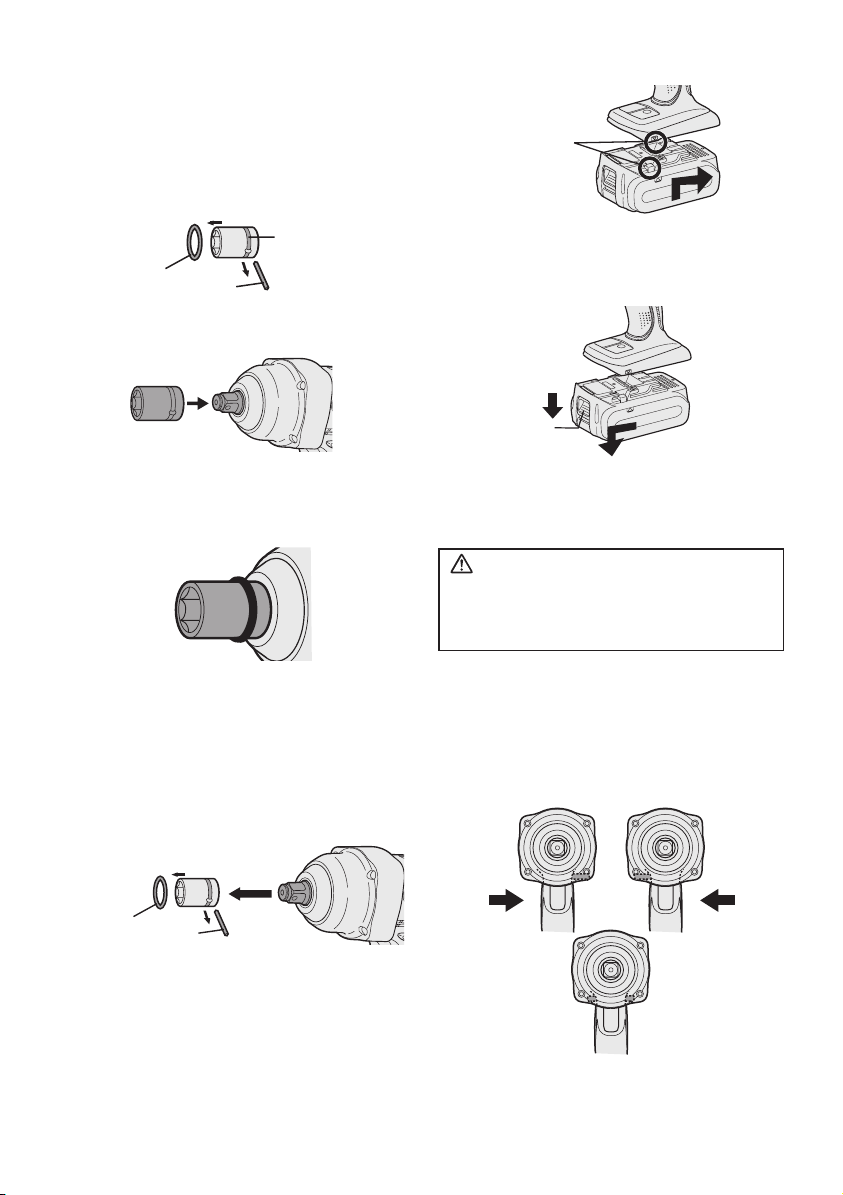
IV. MONTAJE
Instalación o desmontaje
del cubo
1. Instalación del cubo
1) Retire el anillo de caucho y el pasador.
• Deslice la batería hasta que se blo quee
en su posición.
Marcas de
alineación
muesca
anillo de
caucho
2) Acople el cubo colocando los elementos
en cada orificio.
3) Acople el anillo de caucho y el pasador
siguiendo el orden expuesto en 1) de
forma inversa.
NOTA:
Acople el cubo con firmeza utilizando el
pasador y el anillo de caucho.
El anillo de retención está destinado
únicamente a fijación temporal.
2. Desmontaje del cubo
1) Retire el anillo de caucho y el pasador.
pasador
2. Para extraer la batería:
Presione el botón y deslice el paquete de
baterías hacia delante.
Botón
V
.
FUNCIONAMIENTO
¡ADVERTENCIA!
• No respire el humo emitido por la
herramienta o el paquete de baterías, ya
que podría ser nocivo.
[Unidad principal]
Funcionamiento del inter-
ruptor y de la palanca de
avance/marcha atrás
anillo de
caucho
pasador
Colocación y extracción
de la batería
1. Para conectar la batería:
Alinee las marcas de alineación resaltadas
y acople el paquete de baterías.
-
Avance Marcha
atrás
Bloqueo del interruptor
36 -
Page 37

PRECAUCIÓN:
Para impedir que se produzcan daños,
no utilice la palanca de avance/marcha
atrás hasta que la punta esté totalmente
parada.
Funcionamiento del interruptor de rotación de
avance
1. Empuje la palanca para que se produzca
una rotación de avance.
2. Apriete ligeramente el gatillo del disparador para iniciar la herramienta con
lentitud.
3. La velocidad aumenta con la presión del
disparador para un apriete eficiente de
tornillos. El freno funciona y la punta se
detiene inmediatamente cuando suelta el
disparador.
4. Tras utilizarlo, coloque la palanca en su
posición central (bloqueo del interruptor).
Funcionamiento del interruptor de rotación inversa
1. Empuje la palanca para que se pro duzca
una rotación inversa. Compruebe la dirección de la rotación antes de utilizarlo.
2.
Apriete ligeramente el gatillo del dis parador
para iniciar la herramienta con lentitud.
3. Tras utilizarlo, coloque la palanca en su
posi ción central (bloqueo del inter ruptor).
PRECAUCIÓN:
•
Para evitar un aumento excesivo de
tem pe ratura en la superficie de la
herramienta, no haga funcionar continuamente la herramienta utili zando dos o más
baterías. La her ramienta debe enfriarse
antes de cambiar por otra bate ría.
Disparador del control de
velocidad variable
Para determinar el centro de un orificio,
apriete ligeramente el gatillo para que
empiece la rotación lenta de la punta.
Cuanto más se tira del gatillo, mayor es la
velocidad.
PRECAUCIÓN:
Al accionar la herramienta pulsando el
gatillo puede que la rotación tarde unos
instantes en comenzar. Esto no es señal
de un malfuncionamiento.
• Este intervalo ocurre cuando se inicia el
sistema de circuitos de la herramienta
cuando se tira del disparador por
primera vez después de instalar un
nuevo paquete de batería o después
de que la herramienta no ha sido usada
por al menos 1 minuto. La rotación se
iniciará sin ningún intervalo durante
segundas y subsiguientes operaciones.
Panel de indicación
(2)
(1)
(1) Indicador y botón de nivel de batería
• Pulse el botón de nivel de batería.
El indicador de nivel de batería mostrará el
nivel de batería durante aproximadamente
10 segundos.
NOTA:
El indicador no mostrará el nivel de
batería en los siguientes casos, ni siquiera
aunque se pulse el botón.
• La unidad principal se encuentra apagada.
• Justo después de acoplar el paquete de
batería.
• La unidad principal o el botón de nivel
de batería no se acciona durante
aproximadamente un minuto.
Pulse de nuevo el botón de nivel de
batería tras pulsar el gatillo del disparador.
• La temperatura de la batería es elevada.
Detenga el funcionamiento y espere
hasta que disminuya la temperatura de la
batería.
-
37 -
Page 38
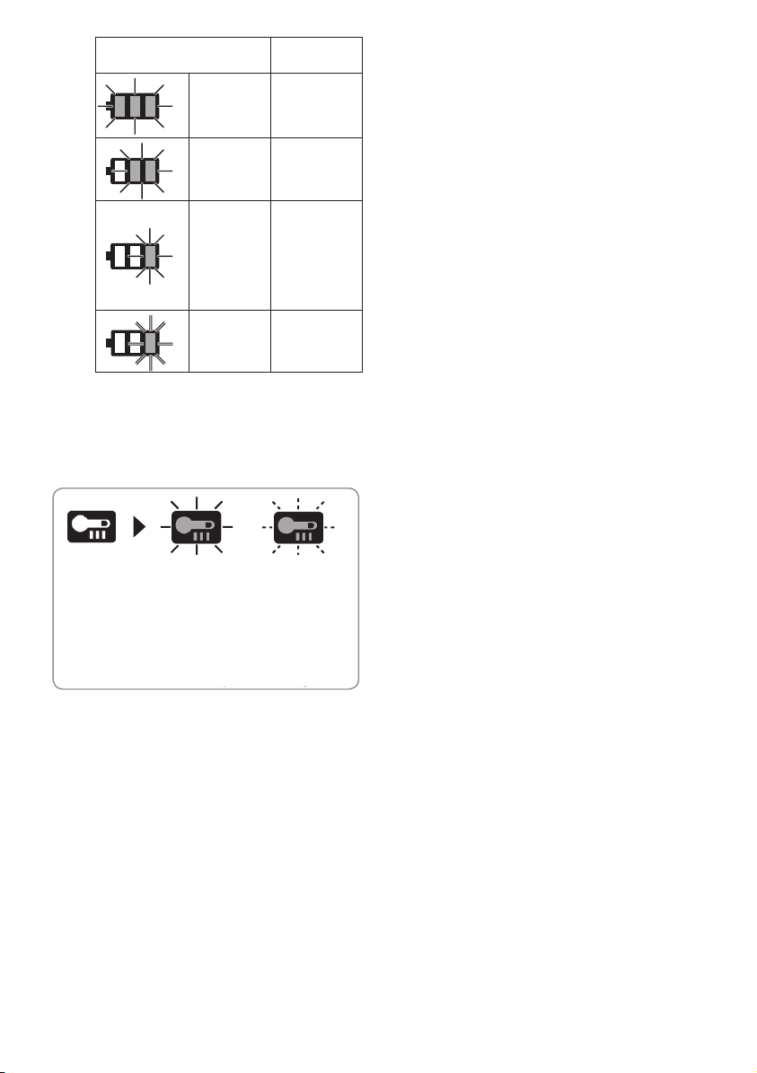
Indicador
3 lámparas
iluminadas
2 lámparas
iluminadas
Una lámpara
iluminada
Una lámpara
parpadeando
Estado de la
batería
Carga
suciente
Queda aprox.
el 50%
El nivel de
carga de la
batería es
bajo.
Debe
cargarse en
breve.
Agotada
Debe cargarse
inmediatamente
La indicación del nivel de batería es
meramente una guía.
La indicación podría cambiar debido al estado
de la batería o la temperatura ambiente.
(3)
Luz de advertencia de sobrecalentamiento
Apagado
Off
(funcionamiento
(normal
normal)
operation)
Iluminado:
Illuminated:
Sobrecalentamiento
Overheat
(motor)
(motor)
Indica que se detuvo el
Indicates operation has
funcionamiento por un
sobrecalentamiento de la
been halted due to motor
batería o el motor.
or battery overheating.
Destella:
Flashing:
Sobrecalentamiento
Overheat
(batería)
(battery)
Para proteger el motor o la batería,
asegúrese de observar lo siguiente
cuando efectúe esta operación.
• Si el motor o la batería se calienta,
se activará la función de protección
y el motor o la batería dejará de
funcionar. La luz de advertencia de
sobrecalentam iento del pane l de
indicación se ilumina o parpadea cuando
esta función está activa.
• Si se activa la función de protección
de sobrecalentamiento, espere hasta
que la herramienta se haya enfriado
completamente (por lo menos 30
minutos). La herramienta está lista
para usar cuando se apaga la luz de
advertencia de sobrecalentamiento.
• Evite utilizar la herramienta de tal
forma que la función de protección
de sobrecal entamie nto se activ e
repetidamente.
• Si la herramienta funciona continuamente
bajo condiciones de carga pesada o si se
usa en condiciones de alta temperatura
(tal como du rante el verano), la
protección contra sobrecalentamiento
puede activarse frecuentemente.
• Si la herramienta se usa en condiciones
de temperatura fría (tal como durante el
invierno) o si se detiene con frecuencia
durante el uso, la protección contra
sobrecalentamiento quizás no se active.
Agarre recomendado
Utilice la empuñadura para sostener y
accionar la herramienta con una sola
mano. Si el trabajo requiere fuerza
adicional, podrá empujar la parte trasera
de la herramienta con la otra mano.
[Bloque de pilas]
Para un uso adecuado de
la batería
Batería de Li-ión
• Para una vida óptima de la batería, guarde
la batería de Li-ión siguiendo el uso sin
carga.
• Cuando cargue la caja de batería, confirme
que los terminales en el cargador de
batería estén libres de materias extrañas
tales como polvo y agua, etc. Limpie los
terminales antes de cargar la caja de
batería si hay materias extrañas en los
terminales.
La vida de los terminales de la caja de
batería puede verse afectada por materias
extrañas tales como polo y agua, etc.
durante su funcionamiento.
• Cuando no se utiliza la batería, manténgala separada de otros objetos metálicos, como: clips de papel, monedas,
llaves, clavos, tornillos u otros objetos
metálicos pequeños que pueden actuar de
conexión entre un terminal y el otro.
Un cortocircuito entre los terminales de
la batería pueden ocasionar chispas,
quemaduras o incendios.
• Cuando haga funcionar con la batería,
asegúrese que el lugar de trabajo está
bien ventilado.
-
38 -
Page 39

• Cuando saque la batería de la unidad
principal de la herramienta, vuelva a cerrar
inmediatamente la cubierta de batería,
para evitar que el polvo o la suciedad
puedan ensuciar los terminales de batería
y provocar un cortocircuito.
Vida útil de la batería
Las baterías recargables tienen una vida
útil limitada. Si el tiempo de funcionamiento se acorta mucho tras la recarga,
sustituya la batería por una nueva.
Reciclado de la batería
ATENCIÓN:
PARA batería Li-ión
La batería de Li-ión que compró es reciclable.
Llame a 1-800-8-BATTERY para información
sobre el reciclado de esta batería.
Recomendaciones de uso
Cubierta de batería
Terminales
materias extrañas tales como polvo y
agua, etc. Limpie los terminales antes de
cargar la caja de batería si hay materias
extrañas en los terminales.
La vida de los terminales de la caja
de batería puede verse afectada por
materias extrañas tales como polo y
agua, etc. durante su funcionamiento.
PRECAUCIÓN:
Para proteger el motor o la batería,
asegúrese de observar lo siguiente
cuando efectúe esta operación.
Si el motor o la batería se calienta, se
activará la función de protección y la
batería dejará de funcionar.
Para un uso más seguro
La batería está diseñada para conectarse
siguiendo dos pasos por motivos de
seguridad. Compruebe que la batería está
conectada correctamente en la unidad
principal antes de utilizar la herramienta.
Si la batería n o ha que d a d o bien
conectada, al activa r el interruptor
parpadearán la lámpara de aviso de
sobrecalentamiento y la lámpara de
aviso de bajo nivel de carga de batería,
para indicar que no es posible un
funcionamiento seguro, y la unidad
principal no girará con normalidad.
Conecte la batería a la unidad de la
herramienta hasta que el indicador rojo o
amarillo desaparezca.
[Cargador de la batería]
rojo
Asegúrese de utilizar la cubierta de
la caja de batería
Cuando no utilice la caja de batería,
guarde la batería de tal forma que las
materias extrañas tales como polvo
y agua, etc. ensucien los terminales.
Asegúrese de colocar la cubierta de la
caja de batería de tal forma de proteger
los terminales de la batería.
Cuando cargue la caja de batería,
confirme que los t e r minales e n e l
cargador de batería estén libres de
-
39 -
Carga
PRECAUCIÓN:
• El cargador está diseñado para funcionar
con alimentación eléctrica doméstica
estándar únicamente tal y como se indica
en la placa de características. Realice la
carga únicamente con la tensión indicada
en la placa de características de la unidad.
P. ej. 230 V/50 Hz.
• No intente utilizarlo con ninguna otra
tensión o frecuencia nominal.
• Si la temperatura del paquete de baterías
cae aproximadamente bajo −10°C (14°F),
la carga se detendrá automáticamente
para evitar la degradación de la batería.
• La variación de temperatura ambiente es
de entre 0°C (32°F) y 40°C (104°F). Si la
batería se utiliza cuando la temperatura
de la batería es inferior a 0°C (32°F),
la herramienta puede no funcionar
correctamente.
Page 40
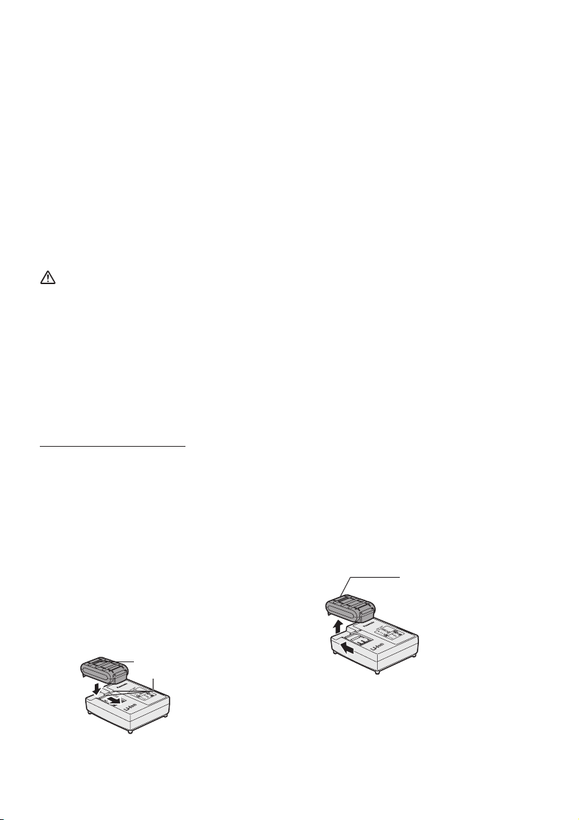
• Utilice siempre el cargador a una
temperatura entre 0°C y 40°C y cargue la
batería a una temperatura similar a la de
la propia batería. (Procure que no haya
una diferencia superior a 15°C entre la
temperatura de la batería y la del lugar
donde se realiza la carga.)
• Cuando se vaya a cargar una batería fría
(unos 0°C (32°F) o menos) en un cuarto
cálido, deje la batería en la habitación
durante al menos una hora y cárguela
cuando se haya calentado a la temperatura
de la habitación.
• Deje que se enfríe el cargador al cargar
más de dos baterías de forma consecutiva.
• No introduzca sus dedos dentro del hueco
del contacto, cuando esté sujetando el
cambiador o en ninguna otra ocasión.
PRECAUCIÓN:
Para impedir el riesgo de incendio o daños
del cargador de batería.
• No tapone los orificios de ventilación del
cargador y la bate ría.
• Desenchufe el cargador cuando no lo
utilice.
NOTA:
Su batería no está totalmente cargada
al momento de comprarla. Asegúrese
de cargar la batería antes de utilizarla.
Cómo cargar el dispositivo
1. Enchufe el cargador en la fuente de
alimentación de CA.
NOTA:
Se pueden producir chispas cuando se
inserta el enchufe en la alimentación
eléctrica de CA pero este no es un
problema en términos de seguridad.
2. Conecte el paquete de batería con firmeza
al cargador.
1 Alinee las marcas de alineación y
coloque la batería en el enchufe del
cargador.
2 Deslice hacia adelante en el sen tido de
la flecha.
Marcas de alineación
3. Durante el proceso de carga la lámpara de
carga permanecerá iluminada.
Cuando haya terminado la carga, se ac cionará automáticamente un conmutador
electrónico interno para impedir cualquier
sobrecarga.
• No podrá cargar la batería si ésta está
todavía caliente (por ejemplo, inmediatamente después de haber trabajado
mucho).
La luz de espera naranja seguirá deste-
llando hasta que se enfríe la batería.
La carga comenzará automáticamente.
4. La luz de carga (verde) destellará lentamente
cuando la batería se haya cargado a un
80%.
5. Cuando se completa la carga, la luz de carga
empezará a destellar rápidamente en color
verde.
6.
Si la temperatura de la batería es de 0°C o
menos, la batería demora más en cargarse
completamente que el tiempo de carga normal.
Incluso cuando la batería esté completamente
cargada, tendrá aproximadamente 50% de
la carga de una batería totalmente cargada
a la temperatura de funcionamiento normal.
7. Si la luz de carga no se enciende
inmediatamente después de enchufar el
cargador o si la luz de carga no empieza a
destellar rápidamente en verde después del
tiempo de carga normal, consulte con un
concesionario autorizado.
8. Si se vuelve a colocar una batería totalmente
cargada en el cargador, se encen derá la
luz de carga. Luego de algunos minutos, la
lámpara de carga destellará rápidamente
para indicar que la carga se ha completado.
9. Extraiga la batería mientras mantiene
levantado el botón de desbloqueo de la
batería.
Botón de desbloqueo
de la batería
-
40 -
Page 41

INDICACIÓN DE LA LÁMPARA
N・m
La carga ha sido completada. (Carga completa.)
La batería se cargó en aproximadamente 80%.
Ahora cargando.
Se ha enchufado el cargador en la fuente de alimentación
de CA. Está preparado para cargar.
(Verde)
Apagada Encendida
(Naranja)
Luz de estado de carga
Aparecerá Izquierda: verde Derecha: naranja
La batería está fría.
La batería se esta cargando lentamente para reducir la carga de la batería.
La batería está caliente.
La carga comenzará cuando baje la temperatura de la batería. Si la temperatura
de la batería es de –10°C o menos, la luz de carga (naranja) también empezará a
destellar. La carga empezará cuando sube la temperatura de la batería.
No es posible realizar la carga. Existe un bloqueo de polvo o una
falla de la batería.
Parpadeando
VI. MANTENIMIENTO
Utilice sólo un paño suave y seco para
limpiar la herramienta. No utilice paños
húmedos, bencina, diluyentes u otros
disolventes volátiles de limpieza.
VII. PAR DE APRIETE
La potencia necesaria para apretar un
perno variará en función del material y el
tamaño del perno, así como del material
que se está acoplando. Elija la duración
del tiempo de apriete en consecuencia.
Se facilitan a continuación los valores de
referencia.
(Pueden variar según las condiciones de
apriete.)
Factores que afectan al par
de apriete
El par de apriete resulta afectado por una
amplia variedad de factores, incluidos los
siguien tes. Tras el apriete, compruebe
siempre el par con una llave de tuercas
de par.
-
41 -
1) Tensión
Cuando la batería se ha prácticamente
descargado, la tensión decrece y el par de
apriete baja.
(㎏f-cm)
M16,M20,M24×45mm
600
(6122)
500
(5102)
400
(4082)
300
(3061)
200
Par de apriete
(2041)
100
(1020)
0.50.0 1.0 1.5 2.0 2.5 3.0
M16, M20, M24 x 45 mm
Perno estándar
M24
M20
M16
Tiempo de apriete (s.)
Page 42

N・m
(㎏f-cm)
3.0
(80% de resistencia de ductilidad)
M16,M20,M24×45mm
600
(6122)
500
(5102)
400
(4082)
300
(3061)
200
Par de apriete
(2041)
100
(1020)
0.50.0 1.0 1.5 2.0 2.5
Perno de alta ductilidad
M20
M16
Tiempo de apriete (s.)
M16, M20, M24 x 45 mm
Perno
Tuerca
Arandela
Placa de acero
grosor 10 mm
Arandela
Arandela de resorte
Condiciones de apriete
• Se utilizan los siguientes pernos.
Perno estándar: Tipo de resistencia 4,8
Tipo de alta ductilidad 12,9
Explicación del tipo de resistencia
4.8
Límite de elasticidad del perno
32 kgf/mm2 (45000 psi)
Resistencia dúctil del perno
40 kgf/mm
2
(56000 psi)
M24
2) Tiempo de apriete
Un tiempo de apriete mayor da como
resultado un par de apriete incrementado.
Un apriete excesivo, no obstante, no
añade valor y reduce la vida útil de la
herramienta.
3) Diámetros diferentes de perno
El tamaño del diámetro de perno afecta al
par de apriete.
En general, al aumentar el diámetro de
perno, asciende el par de apriete.
4) Condiciones de apriete
• El par de apriete variará, incluso con el
mismo perno, según el coeficiente del
tipo, longitud y par (el coeficiente fijo
indicado por el fabricante en el proceso
de producción).
• El par de apriete variará, incluso con el
mismo material del perno (ej. acero), en
función del acabado de la superficie.
• El par se reduce mucho cuando el perno
y la tuerca empiezan a girar juntos.
5) Juego del enchufe
El par disminuye en la medida en que
se utiliza para apretar un perno la
configuración de seis caras del enchufe de
tamaño incorrecto.
6) Interruptor (disparador de control de
velocidad variable)
La torsión baja cuando se utiliza la
unidad con un interruptor no presionado
completamente.
7) Efecto del adaptador de conexión
El par de apriete disminuirá a través del
uso de una junta universal o un adaptador
de conexión.
VIII. ACCESORIOS
Utilice sólo puntas de tamaño adecuado.
IX. ANEXO
MÁXIMAS CAPACIDADES RECOMENDADAS
Modelo
Apriete de perno
Perno normal: M12 – M20
Perno de gran tracción: M12 – M18
INFORMACIÓN ADICIONAL SOBRE LA GARANTÍA
La rotura y los daños provocados por un uso continuado durante un periodo de tiempo prolongado
(por ejemplo trabajos en líneas de montaje de fábricas, etc.) no están cubiertos por la garantía.
-
42 -
EY7552
Page 43

X. ESPECIFICACIONES
UNIDAD PRINCIPAL
Modelo
Motor 18 V DC
Sin velocidad de carga 0 - 1550 min
Torsión máxima 470 N·m
Impactos por minuto 0 - 2400 min
Longitud total 214 mm
Peso (con batería: EY9L50)
Peso (con batería: EY9L51)
Ruido, Vibración Consulte la hoja incluida
EY7552
-1
-1
2,6 kg
BATERÍA
Modelo EY9L50 EY9L51
Batería de almacenaje Batería Li-ión
Tensión de batería 18 V CC (3,6 V x 10 celdas)
CARGADOR DE BATERÍA
Modelo
Régimen
Peso
Vea la placa de especicaciones en la parte inferior del cargador
EY9L50 EY9L51
EY0L81
0,93 kg
Tiempo de carga
Modelo
Régimen
Peso
Tiempo de carga
NOTA: Este cuadro puede contener modelos no disponibles en su país.
Consulte el más reciente catálogo general.
NOTA: Puede consultar el nombre y la dirección del concesionario en la tarjeta de garantía
que se incluye.
Utilizable: 50 min Utilizable: 65 min
Completa: 65 min Completa: 80 min
EY0L82
Vea la placa de especicaciones en la parte inferior del cargador
0,93 kg
EY9L50 EY9L51
Utilizable: 40 min Utilizable: 55 min
Completa: 55 min Completa: 70 min
43 -
-
Page 44

Declaración de interferencias con radiofrecuencias de la
Comisión Federal de Comunicaciones
Este equipo ha sido probado y se ha determinado que cumple con las limitaciones de un
dispositivo digital de Clase B, de conformidad con el Apartado 15 de las regulaciones de FCC.
Estas limitaciones están diseñadas para brindar protección razonable contra las interferencias
perjudiciales en un entorno residencial. Este equipo genera, utiliza y puede irradiar energía
de radiofrecuencia y, si no se instala y utiliza de acuerdo a las instrucciones, puede provocar
interferencias perjudiciales en las comunicaciones de radio. Sin embargo, no existe ninguna
garantía de que no se produzcan interferencias en una instalación concreta. Si este equipo
provoca interferencias perjudiciales en la recepción de radio o televisión, lo que se puede
determinar apagando y encendiendo el equipo, se recomienda al usuario intentar corregir la
interferencia adoptando una de las siguientes medidas:
• Cambie la orientación o posición de la antena receptora.
• Aumente la separación entre el equipo y el receptor.
• Conecte el equipo en una toma de corriente de un circuito que no sea el mismo en el que
está conectado el receptor.
• Consulte por ayuda a un proveedor o un técnico de radio/televisión con experiencia.
Precaución de FCC: Para asegurar un cumplimiento continuo, instale y use el equipo según
las instrucciones provistas. Utilice solamente el paquete de pilas especificado en el manual
de instrucciones. Cualquier cambio o modificación no aprobada expresamente por el grupo
responsable de su certificación puede anular el derecho del usuario sobre el uso del equipo.
Este dispositivo cumple con el Apartado 15 de las regulaciones de FCC. La operación está
sujeta a las siguientes dos condiciones (1) Este dispositivo no puede ocasionar interferencias
que ocasionen daños y (2) este dispositivo debe aceptar cualquier interferencia, incluida una
interferencia que pueda ocasionar una operación no deseada.
Este aparato digital de Clase B cumple con la norma canadiense ICES-003.
-
44 -
Page 45

-
MEMO
-
Page 46

-
MEMO
-
Page 47

-
MEMO
-
Page 48

EN, FR, ES
Two Riverfront Plaza, Newark, NJ 07102
5770 Ambler Drive, Mississauga, Ontario, L4W 2T3
www.panasonic.ca
anihC ni detnirPEY981075521 2013.09
 Loading...