

Panasonic EY7542 User Manual [en, es, fr]
Multi-Impact & Drill Driver
Entraînement perceuse & percussions multiples
Pistola taladradora y múltiples impactos
Operating Instructions
Instructions d’utilisation
Manual de instrucciones
Model No: EY7542
IMPORTANT
This manual contains safety information. Read manual completely before first using this product and save this
manual for future use.
IMPORTANT
Ce mode d’emploi contient des informations sur la sécurité. Lisez-le en entier avant d’utiliser le produit et
conservez-le pour référence.
IMPORTANTE
Este manual contiene información de seguridad. Lea completamente este manual antes de utilizar por primera
vez este producto, y guárdelo para poder consultarlo en el futuro.

Index/Index/Indice
Ni-MH
Ni-Cd
English: Page 3
Français: Page 17 Español: Página 33
FUNCTIONAL DESCRIPTION
DESCRIPTION DES FONCTIONS
DESCRIPCIÓN FUNCIONAL
(A)
(B)
(C)
(O)
(N)(M)
(J)
(D)
(P)
(L) (K)
(H)
(I)
(E)
(F)
(S)
(G)
(G)
(R)
6.35 mm (1/4") hex quick connect chuck
(A)
Clutch handle Poignée de l’embrayage Mango de embrague
(B)
(C)
Impact/Drill driver switch
Forward/Reverse lever
(D)
Belt hook lock lever
(E)
Belt hook Crochet de ceinture Gancho del cinturón
(F)
Alignment marks Marques d’alignement Marcas de alineación
(G)
Battery pack release button Bouton de libération de batterie autonome Botón de liberación de la batería
(H)
Battery pack (EY9L40) Batterie autonome (EY9L40) Batería (EY9L40)
(I)
Control panel Panneau de commande Panel de control
(J)
Overheat warning lamp (battery)
(K)
LED light on/off button Bouton Marche/Arrêt de la lumière DEL Botón ON/OFF de luz LED
(L)
LED light Lumière DEL Luz indicadora
(M)
Battery low warning lamp Témoin d’avertissement de batterie basse Luz de aviso de baja carga de batería
(N)
Variable speed control trigger Gâchette de commande de vitesse
(O)
Battery charger (EY0L80) Chargeur de batterie (EY0L80) Cargador de la batería (EY0L80)
(P)
(Q)
Pack cover
Ni-MH/Ni-Cd battery pack dock
(R)
Li-ion battery pack dock
(S)
Mandrin de connexion rapide hexagonal de 6,35 mm (1/4")
Commutateur de l’entraînement perceuse/percussion
Levier d’inversion marche avant/marche arrière
Levier de verrouillage du crochet de ceinture Palanca de bloqueo del gancho de cinturón
Témoin d’avertissement de surchauffe (batterie)
Couvercle de la batterie autonome Cubierta de batería
Poste d’accueil de la batterie autonome Ni-MH/Ni-Cd
Poste d’accueil de la batterie autonome Li-ion
Mandril hexagonal de conexión rápida de 6,35 mm (1/4")
Interruptor de pistola taladradora/impactos
Palanca de avance/marcha atrás
Luz de advertencia de sobrecalentamiento (batería)
Disparador del control de velocidad variable
Enchufe de carga de batería Ni-MH/Ni-Cd
Enchufe de carga de batería Li-ión
(Q)
-
2 -

-
3 -
I
. INTRODUCTION
This tool is the Multi-Impact & Drill
driver that has 2 operation modes,
“Impact Driver mode” and “Drill Driver
mode”. The modes can be selected by
sliding the impact/drill driver switch.
II
.
GENERAL SAFETY RULES
WARNING! Read all instructions
Failure to follow all instructions listed
below may result in electric shock, fire
and/or serious injury. The term “power
tool” in all of the warnings listed below
refers to your main operated (corded)
po we r to ol and ba tt e ry op er at e d
(cordless) power tool.
SAVE THESE INSTRUCTIONS
Work Area Safety
1) Keep work area clean and well lit.
Cluttered or dark areas invite accidents.
2) Do not operate power tools in explo-
sive atmospheres, such as in the
presence of flammable liquids,
gases or dust.
Power tools create sparks which may
ignite the dust or fumes.
3)
Keep chil dren an d byst ander s
away while operating a power tool.
Distractions can cause you to lose
control.
Electrical Safety
1) Power tool plugs must match the
outlet. Never modify the plug in
any way. Do not use any adapter
plugs with earthe d (groun de d)
power tools.
Unm odif ied plu gs and mat chin g
outlets will reduce risk of electric
shock.
2)
Avoid body contact with earthed or
grounded surfaces such as pipes,
radiators, ranges and refrigerators.
There is an increased risk of electric
shock if you r body is ear th ed or
grounded.
3)
Do not expose power tools to rain
or wet conditions.
Wat er ente ring a po we r tool will
increase the risk of electric shock.
Do not abuse the cord. Never use
4)
the cord for carrying, pulling or
unplugging the power tool. Keep
cord away from heat, oil, sharp
edges or moving parts.
Damaged or entangled cords increase
the risk of electric shock.
When operating a power tool out-
5)
doors, use an extension cord suitable for outdoor use.
Use of a cord suitable for outdoor use
reduces the risk of electric shock.
Personal Safety
1) Stay alert, watch what you are doing
and use common sense when operating a power tool. Do not use a
power tool while you are tired or
under the influence of drugs, alcohol
or medication.
A moment of inattention while operating
power tools may result in personal
injury.
2)
Use safety equipment. Always wear
eye protection.
Safety equipment such as dust mask,
non-skid safety shoes, hard hat, or
hearing protection used for appropriate
conditions will reduce personal injuries.
3)
Avoid accidental starting. Ensure the
switch is in the off position before
plugging in.
Carrying power tools with your finger
on the switch or plugging in the power
tools that have the switch on invites
accidents.
4)
Remove any adjusting key or wrench
before turning the power tool on.
A wrench or a key left attached to a
rotating part of the power tool may
result in personal injury.
5)
Do not overreach. Keep proper
footing and balance at all times.
This enables better control of the
power tool in unexpected situations.
6)
Dress properly. Do not wear loose
clothing or jewellery. Keep your
hair, clothing and gloves away from
moving parts.
Loose clothes, jewellery or long hair
can be caught in moving parts.

-
4 -
7) If device s are provide d for the
connection of dust extraction and
collection facilities, ensure these
are connected and properly used.
Use of these devices can reduce dust
related hazards.
Power Tool Use and Care
1) Do not force the power tool. Use the
correct power tool for your application.
The correct power tool will do the job
better and safer at the rate for which it
was designed.
2)
Do not use the power tool if the
switch does not turn it on and off.
Any power tool that cannot be controlled with the switch is dangerous and
must be repaired.
3)
Disconnect the plug from the power
source and/or the battery pack from
the power tool before making any
adjustments, changing accessories,
or storing power tools.
Such preventive safety measures
reduce the risk of starting the power
tool accidentally.
4)
Store idle power tools out of the
reach of children and do not allow
persons unfamiliar with the power
tool or these instructions to operate
the power tool.
Power tools are dangerous in the
hands of untrained users.
5)
Maintain power tools. Check for
misalignment or binding of moving
parts, breakage of parts and any
other condition that may affect the
power tools operation. If damaged,
have the power tool repaired before
use.
Many accidents are caused by poorly
maintained power tools.
6)
Keep cutting tools sharp and clean.
Properly maintained cutting tools with
sharp cutting edges are less likely to
bind and are easier to control.
7)
Use the power tool, accessories
and tool bits etc. in accordance
with these instructions and in the
manner intended for the particular
type of power tool, taking into
account the working conditions
and the work to be performed.
Use of the power tool for operations
different from those intended could
result in a hazardous situation.
Battery Tool Use and Care
1) Ensure the switch is in the off
position before inserting battery
pack.
Inserting battery pack into power
tools that have the switch on invites
accidents.
2)
Recharge only with the charger
specified by the manufacturer.
A charger that is suitable for one type
of battery pack may create a risk of fire
when used with another battery pack.
3) Use power tools only with specifi-
cally designated battery packs.
Use of any other battery packs may
create a risk of injury and fire.
4)
When battery pack is not in use, keep
it away from other metal objects like
paper clips, coins, keys, nails, screws,
or other small metal objects that can
make a connection from one terminal
to another.
Shorting the battery terminals together
may cause burns, or a fire.
5)
Under abusive conditions, liquid
may be ejected from battery; avoid
contact. If contact accidentally
occurs, flush with water. If liquid
contacts eyes, additionally seek
medical help.
Liquid ejected from the battery may
cause irritation or burns.
Service
1) Have your power tool serviced by a
qualified repair person using only
identical replacement parts.
This will ensure that the safety of
power tool is maintained.
III
.
SPECIFIC SAFETY RULES
1)
Hold power tools by insulated grip-
ping surfaces when performing an
operation where the cutting tool
may contact hidden wiring.
Contact with a “live” wire will make ex-
posed metal parts of the tool “live” and
shock the operator.
-
5 -
2) Wear ear protectors. Exposure to
noise can cause hearing loss.
3)
Be aware that this tool is always in an
operating condition, since it does not
have to be plugged into an electrical
outlet.
4) If the bit becomes jammed, immediately turn the trigger switch off to prevent
an overload which can damage the battery pack or motor. Use reverse motion
to loosen jammed bits.
5)
Do NOT operate the Forward/Reverse
lever when the trigger switch is on.
The battery will discharge rapidly and
damage to the unit may occur.
6)
When storing or carrying the tool, set
the Forward/Reverse lever to the center position (switch lock).
7)
Do not strain the tool by holding the
speed control trigger halfway (speed
control mode) so that the motor stops.
The protection circuit will activate and
may prevent speed control operation.
If this happens, release the speed
control trigger and squeeze again for
normal operation.
8) Be careful not to get dust inside the
chuck.
9) Do not touch the rotating parts to
avoid injury.
10) Do not use the tool continuously for a
long period of time. Stop using the tool
from time to time to avoid temperature
rise and heat overload of the motor.
11)
Do not drop the tool.
Symbol Meaning
V
n
0
… min
Ah
Revolutions or reciprocations
-1
Electrical capacity of battery
Volts
Direct current
No load speed
per minutes
pack
Rotation only
Impact driver mode
WARNING!
Some dust created by power sanding,
sawing, grinding, drillin g , and other
construction activities contains chemicals
known to the State of California to cause
cancer, birth defects or other reproductive
harm. Some examples of these chemicals
are:
• Lead from lead-based paints
• Crys tall i ne si lica fro m bri cks and
cement and other masonry products
• Arsenic and chromium from chemicallytreated lumber.
To re duc e yo u r ex pos ur e to th es e
chemicals: work in a well ventilated area,
and work with approved safety equipment,
such as dust masks that are specially
designed to filter out microscopic particles.
IV
.
FOR BATTERY CHARGER
& BATTERY PACK
Important Safety Instructions
1) SAVE THESE INSTRUCTIONS -This
manual contains important safety
and operating instructions for battery
charger EY0L80.
2) Before using battery charger, read all
instructions and cautionary markings
on battery charger, battery pack, and
product using battery pack.
3) CAUTI ON -To reduce the risk of
injury, charge only Panasonic Battery
Pack as shown in last page.
Other types of batteries may burst
causing personal injury and damage.
4) Do not expose charger and battery
pack to rain or snow.
5)
To reduce risk of damaging the electric
plug and cord, pull by plug rather than
cord when disconnecting charger.
6)
Make sure cord is located so that it
will not be stepped on, tripped over,
or otherwise subjected to damage or
stress.
7) An extension cord should not be used
unless absolutely necessary.
Use of improper extension cord could
result in a risk of fire and electric
shock. If extension cord must be used,
make sure that:

-
6 -
a. pins on plug of extension cord are
the same number, size and shape
as those of plug on charger.
b. extension cord is properly wired
and in good electrical condition.
wire size is large enough for ampere
c.
rating of charger as specified below.
RECOMMENDED MINIMUM AWG SIZE OF
EXTENSION CORDS FOR
BATTERY CHARGERS
AC Input Rating. Amperes
Equal to or
greater than
0 2 18 18 18 16
8) Do not operate charger with damaged
cord or plug-replace them immediately.
9) Do not operate charger if it has received a sharp blow, been dropped, or
otherwise damaged in any way; take it
to a qualified service personnel.
10
) Do not disassemble charger; take it
to a qualified service personnel when
service or repair is required. Incorrect
reassembly may result in a risk of
electric shock or fire.
11)
To reduce the risk of electric shock,
unplug charger from outlet before
attempting any maintenance or cleaning.
12)
The charger and battery pack are
specifically designed to work together.
Do not attempt to charge any other
cordless tool or battery pack with this
charger.
13)
Do not attempt to charge the battery
pack with any other charger.
14)
Do not attempt to disassemble the
battery pack housing.
15)
Do not store the tool and battery pack
in locations where the temperature
may reach or exceed 50°C (122
(such as a metal tool shed, or a car
in the summer), which can lead to
deterioration of the storage battery.
16)
Do not charge battery pack when the
temperature is BELOW 0°C (32°F)
or ABOVE 40°C (104°F). This is very
important in order to maintain optimal
condition of the battery pack.
17)
Do not incinerate the battery pack. It
can explode in a fire.
But less
than
AWG Size of Cord
Length of Cord,
Feet
25 50 100 150
°F)
18)
Avoid dangerous environment. Do not
use charger in damp or wet locations.
19)
The charger is designed to operate
on standard household electrical
power only. Do not attempt to use it
on any other voltage!
20)
Do not abuse cord. Never carry charger
by cord or yank it to disconnect from
outlet. Keep cord away from heat, oil
and sharp edges.
21)
Charge the battery pack in a well ven-
tilated place, do not cover the charger
and battery pack with a cloth, etc., while
charging.
22)
Use of an attachment not recommend-
ed may result in a risk of fire, electric
shock, or personal injury.
23)
D o not short the batter y pac k. A
battery short can cause a large current
flow, over heating and create the risk
of fire or personal injury.
24)
NOTE: If the supply cord of this appli-
ance is damaged, it must only be
replaced by a repair shop authorized
by the manufacturer, because special
purpose tools are required.
25)
TO REDUCE THE RISK OF ELEC-
TRIC SHOCK, THIS APPLIANCE HAS
A POLARIZED PLUG (ONE BLADE IS
WIDER THAN THE OTHER).
This plug will fit in a polarized outlet
only one way. If the plug does not fit
fully in the outlet, reverse the plug. If
it still does not fit, contact a qualified
electrician to install the proper outlet.
Do not change the plug in any way.
V
. ASSEMBLY
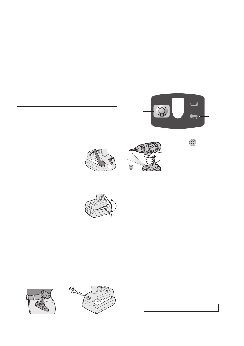
Attaching or Removing Bit
NOTE:
When attaching or removing a bit,
•
disconnect battery pack from tool or
place the switch in the center position
(switch lock).
1. Hold the collar of quick connect chuck
and pull it out from the driver.
2. Insert the bit into the chuck. Release
the collar.
3. The collar will return to its original
position when it is released.
-
7 -
4.
Alignment marks
Button
Forward
Reverse
Switch lock
Pull the bit to make sure it does not come
out.
5. To remove the bit, pull out the collar in
the same way.
CAUTION:
• If the collar does not return to its
original position or the bit comes out
when pulled on, the bit has not been
properly attached. Make sure the bit
is properly attached before use.
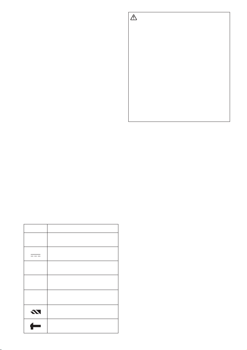
Use 6.35 mm (1/4") hexagonal bits.
To ensure proper securement of the
bit, use only hexagonal bits with 9.5
mm (3/8") detent.
6.35 mm (1/4")
9.5 mm (3/8")
VI
. OPERATION
[Main Body]
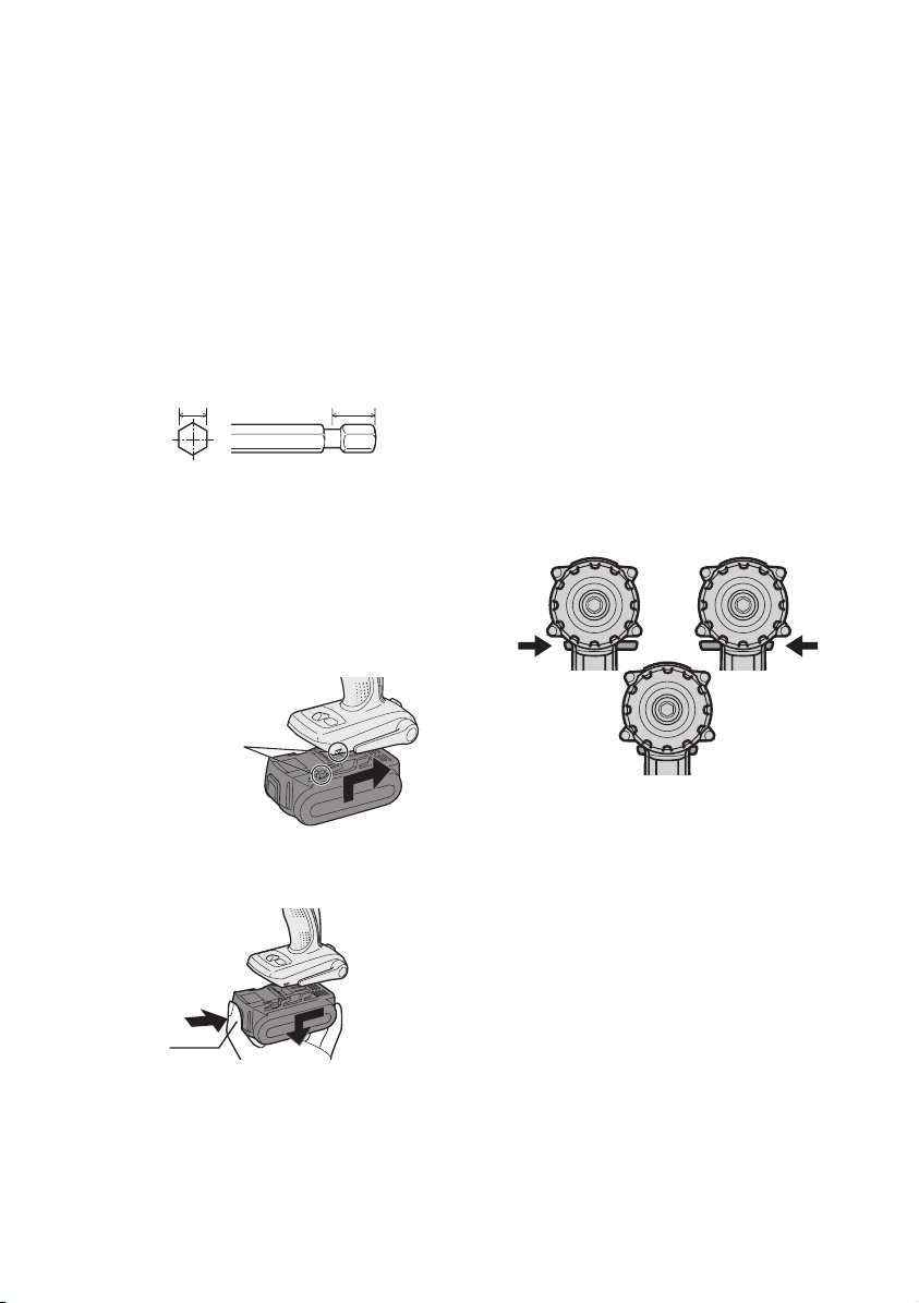
Switch Operation
1. The speed increases with the amount
of depression of the trigger. When
beginning work, depress the trigger
slightly to start the rotation slowly.
2. A feedback electronic controller is
used to give a strong torque even in
low speed.
3. The brake operates when the trig
ger is released and the motor stops
immediately.
NOTE:
When the brake operates, a braking
sound may be heard. This is normal.
-
Attaching or Removing Battery Pack
1. To connect the battery pack:
Line up the alignment marks and attach the battery pack.
Slide the battery pack until it locks
•
into position.
2. To remove the battery pack:
Push on the button from the front to
release the battery pack.
Switch and Forward/Reverse
Lever Operation
CAUTION:
To prevent damage, do not operate
Forward/Reverse lever until the bit
comes to a complete stop.
Forward Rotation Switch
Operation
1. Push the lever for forward rotation.
2. Depress the trigger switch slightly to
start the tool slowly.
3. The speed increases with the amount
of depression of the trigger for efficient tightening of screws and drilling.
The brake operates and the chuck
stops immediately when the trigger is
released.
4. After use, set the lever to its center
position (switch lock).
-
8 -
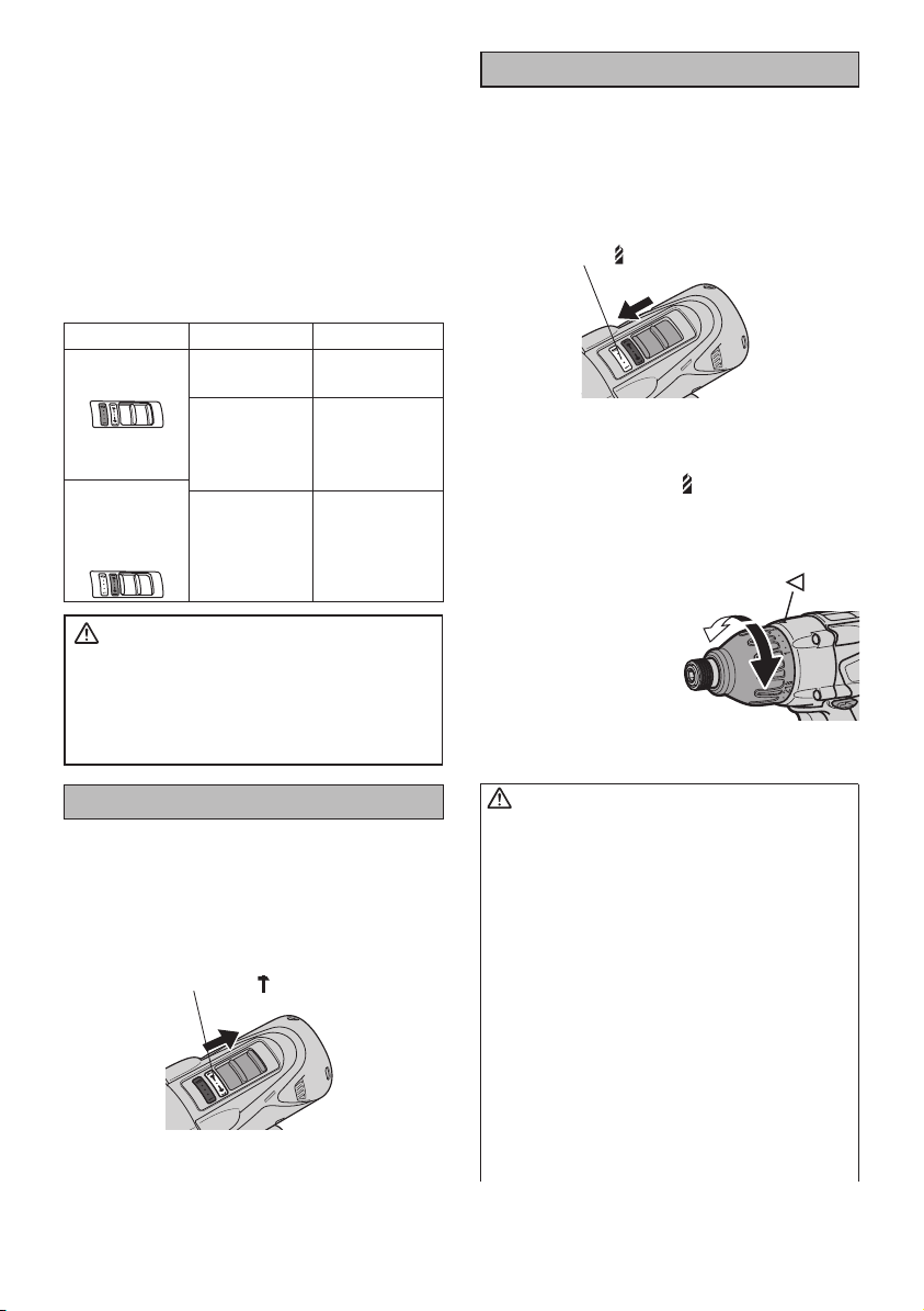
Reverse Rotation Switch
Operation
1. Push the lever for reverse rotation.
Check the direction of rotation before use.
2. Depress the trigger switch slightly to
start the tool slowly.
3. After use, set the lever to its center
position (switch lock).
Selecting Mode
Select mode Intended use Work material
Fastening Bolt
Impact driver
Driving
Drill driver
mode with
clutch function
Drilling
WARNING!
This tool must not be used as a drill in
“Impact Driver mode”. During drilling in
steel, the drill bit may break in case of
blocking and this may cause dangerous
cut wounds.
Impact Driver Operation
Select Impact Driver with the impact/
drill driver switch.
•
Switch to the impact/drill driver position only when the tool has completely
stopped rotating. Damage may be
caused if the tool is rotating.
The impact driver ( mark) display will turn
Nut
Wood screw
Metal screw
Self-driving
screw
Wood
Metal
silver.
Drill Driver Operation
Select Drill Driver with the impact/drill
driver switch.
•
Switch to the impact/drill driver position only when the tool has completely
stopped rotating. Damage may be
caused if the tool is rotating.
The drill driver ( mark) display will turn silver.
Clutch Torque Setting
Adjust the torque to one of the 21
clutch settings or “
CAUTION:
Test the setting before actual operation.
Set the scale at this mark ( ).
How to Use the Belt Hook
WARNING!
• Be sur e to at tach the belt hoo k
securely to the main unit with the
screw firmly fastened. When the belt
hook is not firmly attached to the main
unit, the hook may disconnect and the
main unit may fall.
This may result in an accident or
injury.
• Periodically check screw for tight
ness. If found to be loose, tighten
firmly.
•
Be sure to attach the belt hook firmly
and securely onto a waist belt or other
belt. Pay attention that the unit does not
slip off the belt.
accident or injury.
” position.
-
This may result in an
-
9 -
• When the main unit is held by the
belt hook, avoid jumping or running
with it. Doing so may cause the hook
to slip and the main unit may fall.
This may result in an accident or
injury.
• When the belt hook is not used, be
sure to return it to the storing position. The belt hook may catch on
something.
This may result in an accident or
injury.
•
When the unit is hooked onto the
waist belt by the belt hook, do not
attach driver bits to the unit. A sharp
edge object, such as a drill bit, may
cause injury or an accident.
To Set the Belt Hook Angle
Position
1. Slide the belt hook lock lever 1 and
hold it to unlock the belt hook.
2. Pu ll the be lt hoo k
from storing position
2 and set it.
Release the belt hook
3.
lock lever to
angle of belt hook.
Make sure the belt hook is firmly
4.
locked. Also make sure the belt hook
is firmly locked into position 3.
• The belt hook cannot be locked in this
position. Firmly lock
it into position before
use.
To return the belt hook to the storing
position, follow step 1. and 2. above,
then lower the belt hook.
To secure the lock, follow 3 and 4
above.
lock the
2
1
3
To Change the Belt Hook
Location Side
The belt hook can be attached to
either side of the unit.
1. Set the belt hook at storing position.
2. Loosen the screw turning it coun
ter-clockwise, using a flat metal or
a flat blade screw driver.
3. Take out the belt hook and insert
into the other side of the slot on the
main unit.
4. Fasten the screw firmly, turning it
clockwise.
The belt hook can be taken out from
the main unit only when it is at storing
position.
Control Panel
(1)
(1) LED light
Pressing toggles the
LED light on and off.
The light illuminates with
very low current, and it
does not adversely affect
the performance of the
driver during use or its
battery capacity.
CAUTION:
The built-in LED light is designed to
•
illuminate the small work area temporarily.
Do not use it as a substitute for a
•
regular
flashlight, since it does not
have enough brightness
• Po wer au tom ati cal ly tur ns off
immediately after the battery pack
is installed or when the LED light
is on and the driver has not been
used for 5 minutes or more or when
the LED light is turned off and the
driver has not used for 1 minute or
more. Please depress the switch to
operate the drill again.
This product has the built-in LED light.
This product is classified into “Class 1
LED Product” to IEC (EN) 60825-1:2001.
Class 1 LED Product
.
-
(3)
(2)
-
10 -
Caution : DO NOT STARE INTO BEAM.
Use of controls or adjustments or performance
of procedures other than those specied herein
may result in hazardous radiation exposure.
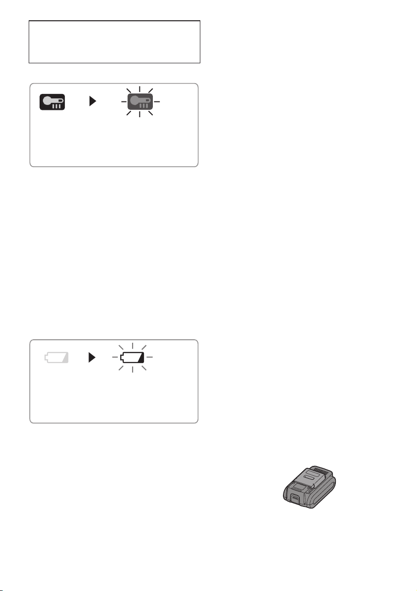
(2) Overheat warning lamp
Off
(normal
operation)
Flashing: Overheat
Indicates operation has
been halted due to battery
overheating.
The overheating protection feature
halts driver operation to protect the
battery pack in the event of overheating. The overheat warning lamp
on the control panel flashes when
this feature is active.
•
If the overheating protection feature
activates, allow the driver to cool
thoroughly (at least 30 minutes).
The driver is ready for use when the
overheat warning lamp goes out.
•
Avoid using the driver in a way that
causes the overheating protection
feature to activate repeatedly.
(3) Battery low warning lamp
Off
(normal
operation)
Flashing
(No charge)
Battery protection
feature active
Excessive (complete) discharging
of lithium ion batteries shortens their
service life dramatically. The driver
includes a battery protection feature
designed to prevent excessive discharging of the battery pack.
• The battery protection feature acti
vates immediately before the battery loses its charge, causing the
battery low warning lamp to flash.
• If you notice the battery low warning
lamp flashing, charge the battery
pack immediately.
Recommended Grip
Use the grip to hold and operate
the driver with one hand. If the job
requires additional force, you can
push against the rear end of the
driver with your other hand.
[Battery Pack]
For Appropriate Use of Bat-
tery pack
Li-ion Battery pack (EY9L40)
• For optimum battery life, store the
Li-ion battery pack following use without charging it.
• When charging the battery pack, con
firm that the terminals on the battery charger are free of foreign substances such as dust and water etc.
Clean the terminals before charging
the battery pack if any foreign substances are found on the terminals.
The life of the battery pack terminals
may be affected by foreign substances
such as dust and water etc. during
operation.
• When battery pack is not in use,
keep it away from other metal objects
like: paper clips, coins, keys, nails,
screws, or other small metal objects
that can make a connection from one
terminal to another.
Shorting the battery terminals togeth-
er may cause sparks, burns or a fire.
• When operating the battery pack,
make sure the work place is well ventilated.
• When the battery pack is removed
from the main body of the tool, replace
the battery pack cover immediately in
order to prevent dust or dirt from contaminating the battery terminals and
causing a short circuit.
-
-
-
11 -
Battery Pack Life
The rechargeable batteries have a
limited life. If the operation time becomes extremely short after recharging, replace the battery pack with a
new one.
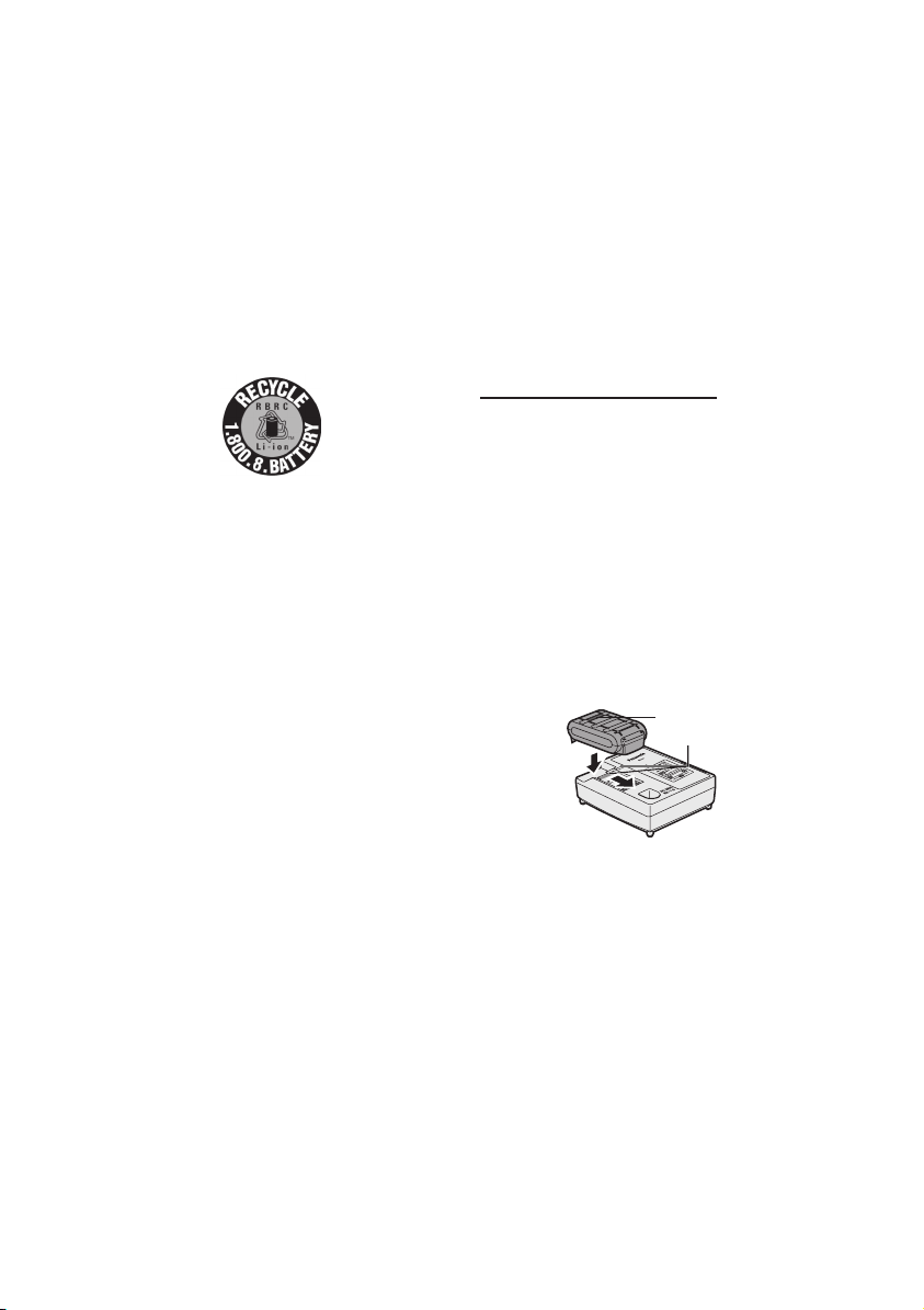
Battery Recycling
ATTENTION:
FOR Li-ion Battery Pack, EY9L40
A Li-ion battery that is recyclable powers
the product you have purchased. Please
call 1-800-8-BATTERY for information on
how to recycle this battery.
[Battery Charger]
Charging
Cautions for the Li-ion Battery
Pack
• If the temperature of the battery pack
falls approx i m a t el y belo w −10°C
(14°F), charging will automatically
stop to prevent degradation of the
battery.
CAUTION:
To prevent the risk of fire or damage
to the battery charger.
• Do not use power source from an
engine generator.
• Do not cover vent holes on the
charger and the battery pack.
• Unplug the charger when not in use.
Li-ion Battery Pack
NOTE:
Your battery pack is not fully charged at the time of purchase. Be sure
to charge the battery before use.
Battery charger (EY0L80)
1. Plug the charger into the AC outlet.
NOTE:
Sparks may be produced when the
plug is inserted into the AC power
supply, but this is not a problem in
terms of safety.
2. Insert the battery pack firmly into the
charger.
1. Line up the alignment marks and
place the battery onto the dock on
the charger.
2. Slide forward in the direction of the
arrow.
Alignment marks
Common Cautions for the Liion/Ni-MH/Ni-Cd Battery Pack
• The ambient temperature range is
between 0°C (32°F) and 40°C (104°F).
If the battery pack is used when the battery temperature is below 0°C (32°F),
the tool may fail to function properly.
• When charging a cool battery pack
(below 0°C (32°F)) in a warm place,
leave the battery pack at the place
and wait for more than one hour to
warm up the battery to the level of the
ambient temperature.
•
Cool down the charger when charging
more than two battery packs consecutively.
• Do not insert your fingers into contact
hole, when holding charger or any
other occasions.
3.
During charging, the charging lamp will
be lit.
When charging is completed, an internal electronic switch will automatically
be triggered to prevent overcharging.
• Charging will not start if the battery
pack is warm (for example, immediately after heavy-duty operation).
The orange standby lamp will be
flashing until the battery cools down.
Charging will then begin automati-
cally.
4. The charge lamp (green) will flash
slow ly on ce wh en th e bat t ery is
approximately 80% charged.
5. When charging is completed, the
charging lamp will start flashing quickly
in green color.

-
12 -
6. If the temperature of the battery pack
is 0°C or less, charging takes longer to
fully charge the battery pack than the
standard charging time.
Even when the battery is fully charged,
it will have approximately 50% of the
power of a fully charged battery at normal operating temperature.
7.
If the power lamp does not light immediately after the charger is plugged
in, or if after the standard charging
time the charging lamp does not flash
quickly in green, consult an authorized
service center.
8. If a fully charged battery pack is inserted into the charger again, the
charging lamp lights up. After several minutes, the charging lamp may
flash quickly to indicate the charging
is completed.
Ni-MH/Ni-Cd Battery Pack
NOTE:
When you charge the battery pack
for the first time, or after prolonged
storage, charge it for about 24
hours to bring the battery up to full
capacity.
Battery charger (EY0L80)
1. Plug the charger into the AC outlet.
NOTE:
Sparks may be produced when the
plug is inserted into the AC power
supply, but this is not a problem in
terms of safety.
2.
Insert the battery pack firmly into the
charger.
Charging will then begin automatically.
4.
When cha r gi ng is compl et e d, the
charging lamp will start flashing quickly
in green color.
5.
If the charging lamp does not light immediately after the charger is plugged in,
or if after the standard charging time the
charging lamp does not flash quickly
in green, consult an authorized service
center.
6. If a fully charged battery pack is inserted into the charger again, the
charging lamp lights up. After several minutes, the charging lamp may
flash quickly to indicate the charging
is completed.
3. During charging, the charging lamp
will be lit.
When charging is completed, an internal electronic switch will automatically
be triggered to prevent overcharging.
• Charging will not start if the battery
pack is warm (for example, immediately after heavy-duty operation).
The orange standby lamp will be
flashing until the battery cools down.
-
13 -
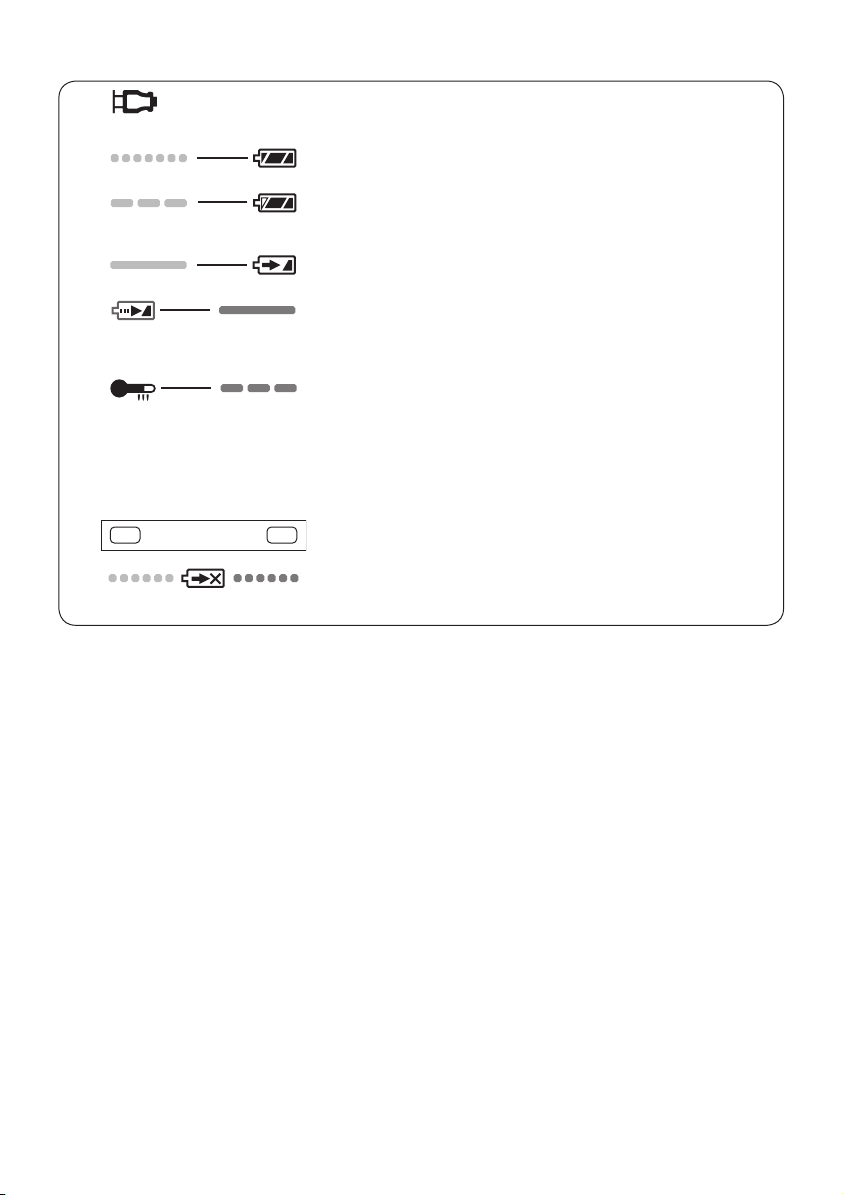
LAMP INDICATIONS
Green Lit
Charger is plugged into the AC outlet.
Ready to charge.
Green Flashing Quickly
Charging is completed. (Full charge.)
Green Flashing
Battery is approximately 80% charged. (Usable charge.
Li-ion only.)
Green Lit
Now charging.
Orange Lit
Battery pack is cool.
The battery pack is being charged slowly to reduce the load
on the battery. (Li-ion only.)
Orange Flashing
Battery pack is warm. Charging will begin when temperature
of battery pack drops.
If the temperature of the battery pack is –10°C (14°F) or less,
the charging status lamp (orange) will also start flashing.
Charging will begin when the temperature of the battery pack
goes up (Li-ion only).
Charging Status Lamp
Left: green Right: orange will be displayed.
Both Orange and Green Flashing Quickly
Charging is not possible. Clogged with dust or malfunction of
the battery pack.
VII
. MAINTENANCE
Use only a dry, soft cloth for wiping the unit. Do not use a damp cloth, thinner, benzine, or other volatile solvents for cleaning.
VIII
.
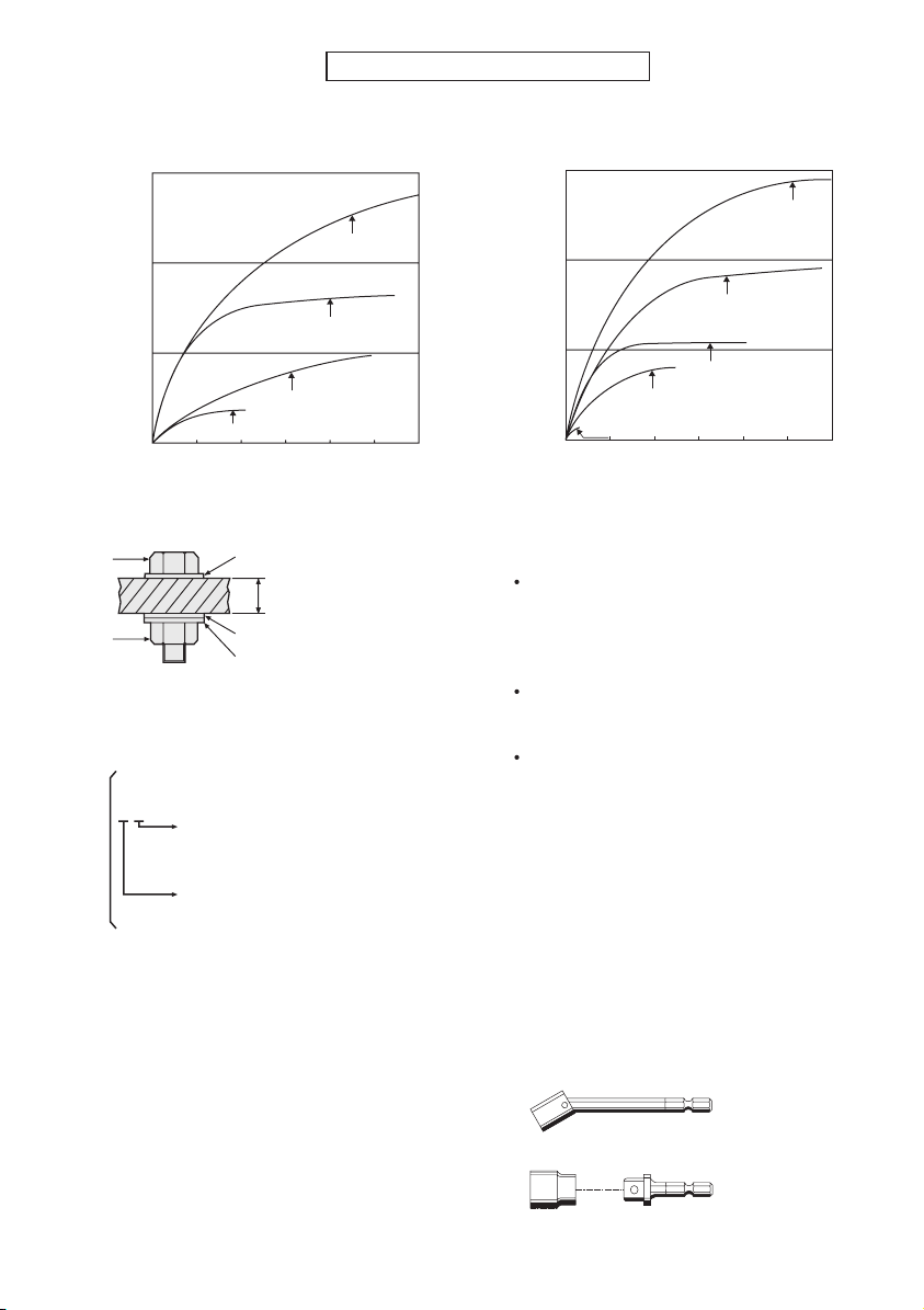
TIGHTENING TORQUE
The power required for tightening a bolt will vary, according to bolt material and size,
as well as the material being bolted. Choose the length of tightening time accordingly.
Reference values are provided below.
(
They may vary according to tightening conditions.
)
Factors Affecting Tightening Torque
The tightening torque is affected by a wide variety of factors including the followings. After tightening, always check the torque with a torque wrench.
1) Voltage
When the battery pack becomes nearly discharged, the voltage decreases and the
tightening torque drops.
-
14 -
Bolt Tightening Conditions
0.50.0 1.0 1.5 2.0 3.02.5
M6
M12
M8
M10
50
100
150
N⋅m
(kgf-cm)
0.50.0 1.0 1.5 2.0 3.02.5
M6
M12
M14
M8
M10
50
100
150
N⋅m
(kgf-cm)
4.8
Explanation of the strength type
Bolt yield point
(80% of tensile strength)
32 kgf/mm2 (45000psi)
Bolt tensile strength
40 kgf/mm2 (56000psi)
M8, M10 x 35mm. M12 x 45mm
High tensile bolt
(Bolt size: Millimeters)
M10 x 35mm. M12, M14, M16 x 45mm
Standard bolt
Tightening torque
Tightening time (Sec.)
Bolt
Nut
Washer
Washer
Spring washer
Tightening conditions
• The following bolts are used.
Standard bolts: Strength type 4.8
High tensile type 12.9
2) Tightening time
Longer tightening time results in in-
creased tightening torque. Excessive
tightening, however, adds no value
and reduces the life of the tool.
3) Different bolt diameters
The size of the bolt diameter affects
the tightening torque.
Generally, as the bolt diameter increases, tightening torque rises.
Steel plate
thickness10 mm (3/8")
Tightening torque
Tightening time (Sec.)
4) Tightening conditions
Tightening torque will vary, even with
the same bolt, according to grade,
length, and torque coefficient (the fixed
coefficient indicated by the manufac
turer upon production).
Tightening torque will vary, even with
the same bolting material (e.g. steel),
according to the surface finish.
Torque is greatly reduced when the
bolt and nut start turning together.
5) Socket play
Torque is lowered as the six-sided configuration of the socket of the
wrong size is used to tighten a bolt.
6) Switch (Variable speed control trigger)
Torque is lowered if the unit is used
with the switch not fully depressed.
7) Effect of Connecting Adapter
The tightening torque will be lowered
through the use of a universal joint or
a socket adapter.
•
Universal joint
• Socket adapter
-
-
15 -
IX
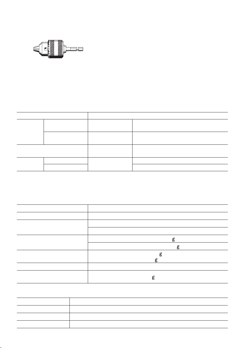
. ACCESSORIES
Drill chuck
• EY9HX409E
Use with screw driver bit, wood drill bit or metal drill bit with straight shank of 1.5
mm to 10 mm diameter.
Universal Joint (Available on the market)
Socket Adapter (Available on the market)
X
.
MAXIMUM RECOMMENDED CAPACITIES
Model EY7542
Screw
driver
Bolt fastening Impact mode
Drill
Wood screw
Self-drilling screw
Steel
Wood ø 21 mm (53/64")
Impact mode
Drill driver mode
Impact mode
Drill driver mode
Drill driver mode
ø 9.5 mm (3/8")
ø 6.2 mm (1/4")
ø 6 mm (15/64")
ø 6 mm (15/64")
Standard bolt: M14
High tensile bolt: M12
ø 10 mm (25/64")
XI
. SPECIFICATIONS
MAIN UNIT
Model EY7542
Motor 14.4 V DC
No load speed
Maximum torque
Clutch torque
Overall length 193 mm (7-1/2")
Weight
(with battery pack: EY9L40)
Drill driver mode: 14.0 N·m (143 k f-cm, 124 in-lbs)
Impact mode: 0 – 2350 min
Drill driver mode: 0 – 700 min-1 (rpm)
Impact mode: 140 N·m (1430 k f-cm, 1239 in-lbs)
Approx. 0.7 N·m (7 k f-cm, 6.2 in-lbs) –-
4.4 N·m (45 k f-cm, 39 in-lbs)
1.65 k (3.61 lbs)
BATTERY PACK
Model EY9L40
Storage battery Li-ion Battery
Battery voltage 14.4 V DC (3.6 V × 4 cells)
Capacity 3 Ah
-1
(rpm)
 Loading...