

Page 1
Operating Instructions
Bedienungsanleitung
Instructions d'utilisation
Istruzioni per I'uso
Gebruiksaanwijzing
Manual de instrucciones
BrugsveJIedning
Driftsföreskrifter
Bruksanvisning
Käyttöohjeet
Инструкция по эксплуатации
1нструкц1я 3 експлуатац1Т
Panasonic
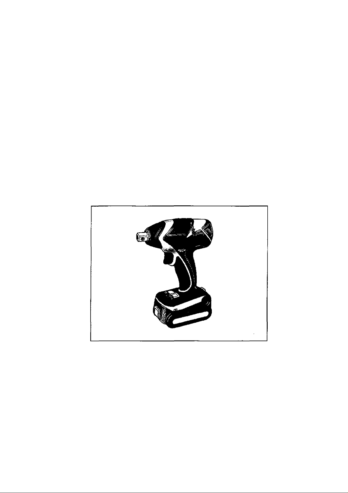
Cordless Impact Wrench
Akku-Schlagschrauber
Ctéà chocs sans fi!
Chiave ad impulsi senza fili
Snoerloze slagsieutel
Llave de impacto inalámbrica
Akku-slagnogle
Sladdlös slagskruvnyckel
Trádios slagskrunokkel
Ladattava pyöröiskuväännin
Ударный аккумуляторный гайковерт
Ударний акумуляторний гайковерт
Model No: EY7541
Before operating this unit, please read these ihstruclions completely and save this manual for future use.
Ver Inbetriebrtahme des Gerätes de Betîebsanleiiiiig bitte gündlich dürdileser und dese Broschüre am ^täieren Nachschiagen soi^äl^ eufbEMahren.
lie enüÈfemenl les rstiucsioins suivantes awantde faire fottcüontœr fapparei et conserver ce mode cfeoploi h des finsde constâalion ultérieure.
Prima di usare questo apparecchio, leggere completamente queste istruzioni e conservare il manuale per usi futuri.
Lees deze gebruiksaanwgiig aandadtig door voor u het apparaat h gebruk neemt en bewaar de gebruiksaanwpjng voor evenLiele naslag.
Antes de usar este aplato por primera vez lea todas las instrucciones de este manual y guarde el manual para poderlo consultar en el futuro.
Gennemlæs denne beyeningsvejiedníng for brugen og gern den til fremtidig brug.
Läs igenom hela bruksanvisningen innan produkten tas i bruk. Spara bruksanvisningen för señare användning.
Feir anhelen las i bruk, venrligst les disse alle anvisningene og oppbevar bruksanvisningen for senere bruk.
Lue ohjeet huolella ennen lartteen käyttöönottoa ja sáilyta tämä käyttöohje tallessa tulevaa tarvetta varíen.
Перецэнллуаш^данногоустрайсгз^ гшагуйсш, псшхлъю прочапв;^»ую инстгуп^и» и сйсфагиш дагте руюкдаво дгя roiuitaoeamn абудуир*.
Парад аишуатецею даного [фистрою, будь ласка, повнело rvxxknaíire дану ¡жлрукц1)° i эбервштъ ïï для виюристання у майбулньому.
Page 2
Index/Index/Index/Indice/Index/Indice/Indeks/Index/Indeksyi-lakemisto/MHAeKc/lHAeKc
English: Page 5 Dansk: Side
Deutsch: Seite
Français: Page 0 Norsk:
Italiano: Pagina
Nederlands:
Español: Página
Bladzijde
0
0 Suomi: Sivu
0
0
Svenska:
Русский:
УкраТнська:
Sid 0
Side 0
Страница 0
СторЫка 0
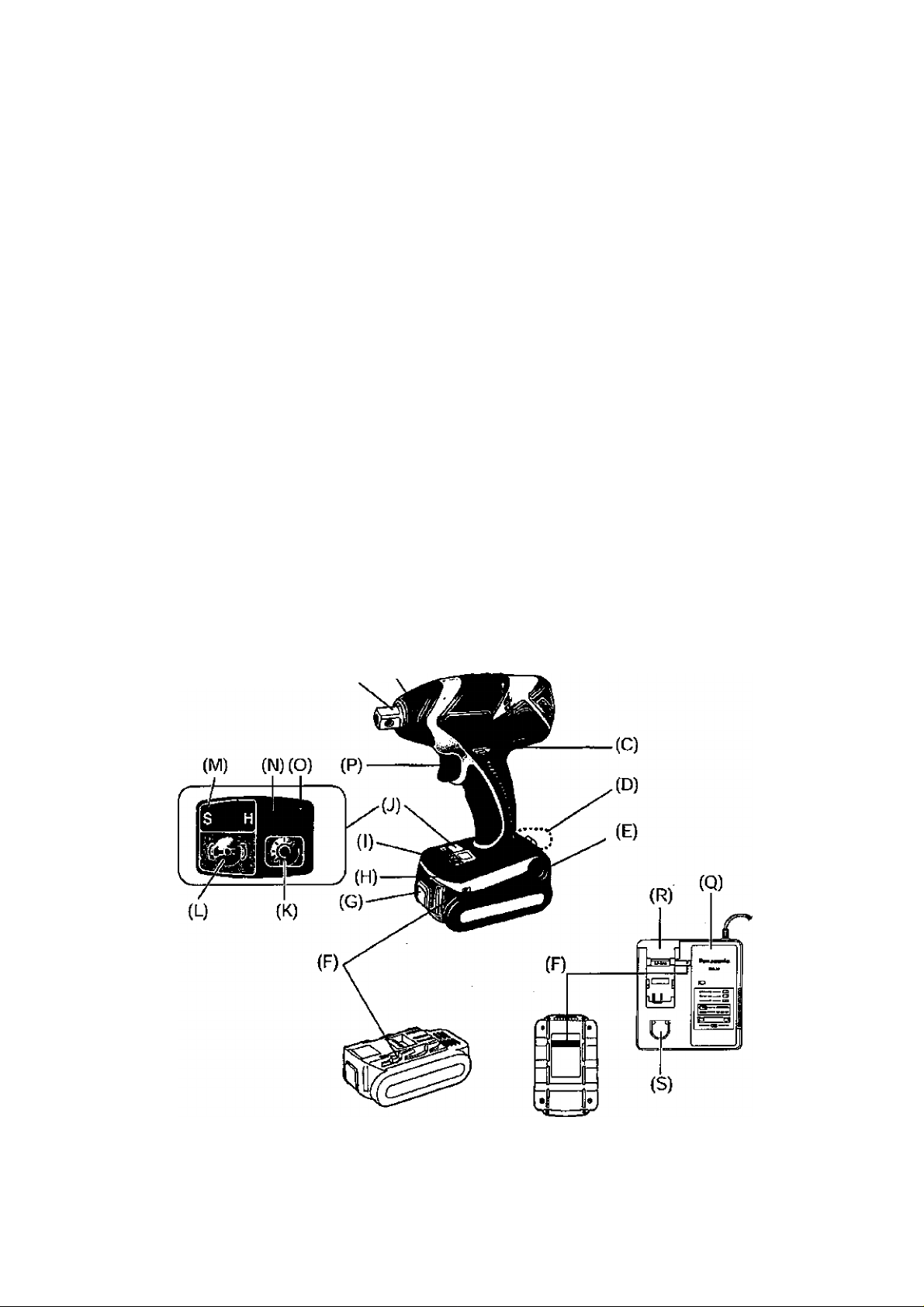
FUNCTIONAL DESCRIPTION
FUNKTIONSBESCHREIBUNG
DESCRIPTION DES FONCTIONS
DESCRIZIONE DELLE FUNZIONI
FUNCTIEBESCHRIJVING
DESCRIPCIÓN FUNCIONAL
FUNKTIONSBESKRIVELSE
FUNKTIONSBESKRIVNING
FUNKSJONSBESKRIVELSE
TOIMINTOJEN KUVAUS
0
0
ФУНКЦИОНАЛЬНОЕ ОПИСАНИЕ
ФУНКЦЮНАЛЬНИЙ ОПИС
(А) (В)
-г-
Page 3

Square drive (bail deten0
Putter
Mandiin
A
Forward/Reverse lever
Vorwarts/Rückwártshebel Riemenhaken-Verríegelungshebel
Levier d’inversion marche avant/marche arrière
Leva di avanzamento^nversione
Links/rechisscKakclaar
Palanca de avance/marcha atrás
С
Greb til forlaens/bagleens retning Lâsehàndtag til bæltekrog
Riktningsomkopplare
Porover-Ли ко ver bryte г Lâsespak for beltekrok
Eteenpain/taaksepaìn vípu
Рычаг переключения вперед/назад
Важ1ль леремикання вперед/нааад Важшь ф1ксацП' поясного хрюка
Belt hook
Ríemenhaken
Crochet de ceinture
Gando da cintura
Riemclip
Gancho del cinturón
F
Baeitekrog
Baiteskrok
Beltekrok
VyOlenkki
Поясной крюк
Поясняй хрюк
Battery pack release button
AkkU'Entriegelungsknopf Akku (EY9L40)
Bouton de liberation de batterie autonome Batterie autonome (EY9L40)
Tasto di rilascio pacco batteria Pacco batteria (EY9L4Û)
Леей- ontgre ndeltoets Accu (EY9L40)
Botón de liberación de batería
Udioserknap til batteri pakning
FrigOringsknapp fOr batteri
utleserknapp for batteripakke Batteripakke (EY9L40]
Akkupaketin irrotuspainike
Кнопка освобождвкия батарейного блока
Кнопка вившьнання батарейного блоку Батарейний блок (EY9L40)
LED light
LED-LeueJite
Lumière DEL
Luce LED
LED-lampJe
Luz indicadora
t
LED-lys Kontrolpanel
LED-t¡us
LED lys
LED-valo
Сееггаднодная подсветка
СвЬглоо1ацне п1дсв1чування
Nose protector
Frontabdeckung
Protection du bec
Protezione frontale
Neusbeschermer
Protector del morro
В
Næsebeskytter
Nosskydd
Nés ebesky Iter
Kâtjen suojus
Респиратор
Pecnlparop
Вей hodt lock lever
Levier de verrouillage du crochet de ceinture
Leva di blocco gancio da cintura
Borland el voor riemclip
Palanca de bloqueo del gancho de cinturón
п
Lâsknapp fûr bSIteskrok
Vyólenkin lukkusvlpu
Рычаг фиксации поясного крюка
Alignment marks
Ausrichtmarkier ungen
FR
IT
NL
ES
Р
DK
SE
NO
FI
RU
Ukr
Battery pack (EY9L4Û)
Batería (EY9L40)
И
Batleripakning (EY9L40)
Batteri (EY9L40)
Akku (EY9L40)
Батарейный блок (EYGL40)
Control panel
Bedienfeld
Panneau de commande
Pannello di controllo
Bedieningspaneel
Panel de control
1
Kontrollpanel
Kontro II panel
saatópaneeli
Панель управления
Панель упраалЫня
- 3 -
Page 4

LED light OM/oOFF button
LED-Leuchten-EIN/AUS-Taste
Bouton Marche/Arrél de la lumifere DEL
Tasto di accensione e spegnirrento della luce LED
Aan/uit-toets (ON/OFF) voor LED-lampje
Beton ON/OFF de lui LED
к
T/END/SLUK-knaptil LED-Iys
Stròmbrytare ftìr LED-Ijus
PA/AV'knapp for LED-Iys
LED-valon kytkin/katkaìsupainikc
Кнопка вилняения/выклкмениясеегодмщной пещеветки
Кнопка вб1ы>1нення/вимкненш1 [»¡П1ОД|однаго п|дс^нування
Impact power mode display
Schlagkraftmodusanzeige
FR
IT
NL
ES
M
DK
SE
NO
Fl
RU
Ukr
Overheat warning lamp (motor/battery)
Ü berhitzungs-Warn lampe (Motor/Akku)
FR
IT
NL
ES
DK
SE
NO
Fl
RU
Ukr
Ваиету charger (EYOL80)
Ladegerät (EY0L8OJ
Chargeur de batterie (EY0L80)
Caricabatteria (EY0L8O)
Acculader (EY0L80)
Cargador de baterías (EYOL80)
Batterioplader (EYOL80)
Batteriladdare (EYOLSO)
Battefilader (EYOLSO)
Akkulaturi (EYOLSO)
Зарядное устройство (EY0L80)
Зарядний npMCTpiñ (EYPLeO)
Ni-MH/Ni-Cd battery pack dock
Ni-MH/Ni-Cd-Akkudock
FR
IT
NL
ES
DK
SE
NO
Fl
RU
Ukr
Impact power mode button
Schlagkraftmodus-Wa hitaste
FR
IT
NL
ES
DK
SE
NO
FI
RU
Ukr
Battery low warning lamp
Akkuladungs-Warnlampe
FR
IT
NL
ES
N
DK
SE
NO
Fi
RU
Ukr
Variable speed control trigger
Elektronikschalter
Gâchette de commande de vitesse
Grilletto di controllo velocità variabile
Slartschakeiaar met variabele toerentalregeiing
Disparador del control de velocidad variable
Kontroludloser for variabei hastighed
Avtryckare med variabel varvtalsreglering
Hovedbryter, trinnios
Nopeudensââtükytkin
Переключатепь регулировки переменной скорости
Перамикан регупювання зм1нноТ швидкрст!
Li-ion battery pack dock
Li-lon-Akkudock
FR
IT
NL
ES
R
DK
SE
NO
Fl
RU
Ukr
- 4 -
Page 5

Read “the Safety Instructions” booklet
and the following before using.
Symbol
Meaning
I. ADDITIONALSAFETY
RULES
1) Wear ear protectors when using the
tool for extended periods.
2) Be aware that this too! is always in an
operating condition, since it does not have
to be plugged into an electrical outlet.
3) When screwing or driving into walls, floors,
etc., live” electrical wires may be encountered. DO NOT TOUCH THE HEX QUICK
CHUCK OR ANY FRONT METAL PARTS
OF THE TOOL! Hold the tool only by the
plastic handle to prevent electric shock in
case you screw or drive into a “live" wire.
4) Do NOT operate the Forward/Reverse
lever when the main switch is on. The bat
tery will discharge rapidly and damage to
the unit may occur.
5) During charging, the charger may become
slightly warm. This is normal.
Do NOT charge the battery for a long peri
od.
6) When storing or carrying the tool, set the
Forward/Reverse lever to the center posi
tion (switch lock).
7) Do not strain the tool by holding the speed
control trigger halfway (speed control
mode) so that the motor stops.
8) Young children should be supervised to
ensure that they do not play with the appli
ance.
V
—
Ho
.../min
Ah
|ui|A|
Revolutions or reciprocations per
Electrical capacity of battery
Read the operating instructions
For indoor use only.
Volts
Direct current
No load speed
minutes
pack
before use.
n. ASSEMBLY
NOTE:
When attaching or removing a bit or
socket, disconnect battery pack from
tool or place the trigger switch in the
center position (switch lock).
Attaching or Removing Socket
1, Attaching Socket
Attach the socket by sliding the female
detent on the bottom of the socket to
the square drive on the body.
Make sure the
socket is firm
ly connected
to the body.
2. Removing Socket
Pull out the socket.
-5 -
Page 6

Attaching or Removing Bat
tery Pack
1, To connect the battery pack:
Line up the alignment marks and attach
the battery pack.
■ Slide the battery pack until it locks into
position.
Aiignment
marks
Forward Rotation Switch Operation
1. Push the lever for forward rotation.
2. Depress the trigger switch slightly to start
the tool slowly.
3. The speed increases with the amount of
depression of the trigger for efficient tight
ening of screws. The brake operates and
the bit stops immediately when the trigger
is released.
4. After use, set the lever to its center posi
tion (switch lock).
2. To remove the battery pack:
Push on the button from the front to re-
iease the battery pack.
Button
III. OPERATION
[Main Body]
Switch and Forward/Reverse
Lever Operation
CAUTION:
To prevent damage, do not operate
Forward/Reverse lever until the bit
comes to a complete stop.
Reverse Rotation Switch
Operation
1. Push the lever for reverse rotation. Check the
direction of rotation before use.
2. Depress the trigger switch slightly to start the
tool slowly
3. After use, set the lever to its center posi
tion {switch lock).
CAUTION:
■ To eliminate excessive temperature
increase of the tool surface, do not
operate the tool continuously using two
or more battery packs. Tool needs cool
off time before switching to another
pack.
How to Use the Beit Hook
A WARNING!
• Be sure to attach the belt hook securely to
the main unit with the screw firmly fastened.
When the belt hook is not firmly attached to
the main unit, the hook may depart and the
main unit may fall.
This may result in an accident or injury.
• Periodicaiiy check screw for tightness. If
found to be loose, tighten firmly.
• Be sure to attach the belt hook firmly arx)
securely orio a waist belt or other belt. Pay
attention to the unit not slipping off from the
belt. This may result in an accident or injury.
• When the main unit is held by the belt
hook, avoid jumping or running with it.
Doing so may cause the hook to slip and
the main unit may fall.
This may result in an accident or injury.
- 6 -
Page 7

• When the belt hook is not used, be sure
to return it to the storing position. The belt
hook may catch on something.
This may result in an accident or injury.
• When the unit is hooked onto the waist beit
by the belt hook, do not attach driver bits to
the unit. A sharp edge object, such as a drill
bit, may cause injury or an accident.
____
To Set the Belt Hook Angle
Position
1. Slide the belt hook lock lever i and hold
it to unlock the belt hook.
2. Pull the belt hook from
storing position 2 and
set it.
3. Release the belt hook
lock lever to lock the
angle of belt hook.
4. Make sure the belt hook is firmly locked.
Also make sure the belt hook is firmly
locked into position 3.
• The belt hook cannot
be locked in this posi
tion. Firmly lock it into
position before use. \s
To return the belt hook to the storing position,
Follow step 1. and 2. above, then lower the
belt hook.
To secure the lock, follow 3 and 4 above.
To Change the Belt Hook
Location Side
The belt hook can be attached to either
side of the unit.
1. Set the belt hook at storing positon.
2. Loosen the screw turning it counter
clockwise, using a flat metal or a flat
blade screw driver.
3. Take out the belt hook and insert into
the other side of the slot on the main
unit.
4. Fasten the screw firmly, turning it clock
wise.
The belt hook can be taken out from the
main unit only when it is at storing posi
tion.
Control Panel
(4) (3)
Impact Power Mode Select
(1)
Selecting the impact power among 3
modes {Soft, Medium, Hard),
Press the impact power mode button to set
it. The mode changes to hard, medium, or
soft each time the button is pressed.
The driver is preset to "hard" impact mode
setting when shipped from the manufac
turer.
Recommended work guideline table
Impact
Power mode
Display
Approx.
3000 b.p.m.
(Max.)
Approx.
Z800 b.p.m,
(Max.)
Approx.
ZOOD b.p.m.
(Max.)
Recommended Application
Jobs requiring a high level
of torque where there is
no possibility of the screw
breaking, its lop shearing off,
or the bit coming loose. (This
setting provides maximum
torque.) Suitable applications
include:
• Tightening M8 and larger
bolts
• Tightening long screws
during interior finishing work
Jobs requiring limited torque
where there b a possibi% oi
the screw breaking or ib top
shearing off. (This setting limits
torque.) Suitable applications
include:
• Tightening bolts with
smaller diameters (M5)
• Tightening metalwork
screws when installing
fixuires
Jobs requiring limited torque
where there is a possibility
of the screw breaking, its
top shearing off. or the bit
coming loose and damaging
a finieiied exterior surface.
(This setting limits torque.)
Suitable applications indude:
• Tightening bolls smaller
than MB that may shear
easily
• Tightening screws into
molded pfastic
• Installing gypsum wallboard
- 7 -
Page 8

(2) LED light
Pressing the @ button tog
gles the LED light on and off.
The light illuminates with
very low current, and it
does not adversely affect
the performance of the
driver during use or its battery capacity.
CAUTION:
• The built-in LED light is designed to illu
minate the small work area temporarily.
• Do not use it as a substitute for a regu
lar flashlight, since it does not have
enough brightness.
This product has the built-in LED light.
This product is classified into "Class 1 LED
Product" to EN 60825-1
Excessive (complete) discharging of Li-
ion batteries shortens their service life
dramatically. The driver includes a battery
protection feature designed to prevent
excessive discharging of the battery pack.
• The battery protection feature activates
immediately before the battery loses its
charge, causing the battery low warning
lamp to flash.
• If you notice the battery low warning
lamp flashing, charge the battery pack
immediately.
[Battery Pack]
For Appropriate Use of Bat
tery Pack
Class 1 LED Product
Caution : DO NOT STARE INTO BEAM,
(3) Overheat warning lamp
• m-
y I ^
Off (normal
operation)
The overheating protection feature halts
driver operation to protect the motor and
battery pack in the event of overheating.
The overheat warning lamp on the control
panel flashes when this feature is active.
* If the overheating protect'ion feature acti
vates, allow the driver to cool thoroughly
(at least 30 minutes), The driver is ready
for use when the overheat warning lamp
goes out.
• Avoid using the driver in a way that
causes the overheating protection fea
ture to activate repeatedly,
(4) Battery low warning lamp
----------------------------—
Off (normal
operation)
Flashing: Overheat
Indicates operation has
been halted due to motor
or battery overheating.
________________________,
\ 1 /
► -a-
1 ^
Flashing (No charge)
Battery protection
feature active
Li-ion Battery Pack (EY9L40)
• For optimum battery life, store the Li-ion
battery pack following use vwthout charg
ing it.
• The ambient temperature range is
between 0"C (32*F) and 40*C (104"F).
If the battery pack is used when ffie battery
temperatLffe is below 0"C (32°F), the tool
may fail to function properly. In that case,
charge the battery until charging is complet
ed for appropriate functioning of the battery.
• When battery pack is not in use. keep it
away from other metai objects like: paper
clips, coins, keys, nails, screws, or other
small metal objects that can make a con
nection from one terminal to another.
Shorting the battery terminals together
may cause sparks, bums or a fire.
•When operating the battery pack, make
sure the work place is welt ventilated.
Battery Pack Life
The rechargeable batteries have a lim
ited life. If the operation time becomes
extremely short after recharging, replace
the battery pack with a new one.
Battery Recycling
ATTENTION:
For environmental protection and recy
cling of materials, be sure that it is dis
posed of at an officially assigned loca
tion, if there is one in your country.
- 8 -
Page 9

[Battery Charger]
Charging
Common Cautions for the Liion/Ni-MH/Ni-Cd Battery Pack
NOTE;
• When charging a cool battery pack
(below 0‘C (32°F)} in a warm place,
leave the battery pack at the place and
wait for more than one hour to warm up
the battery to the level of the ambient
temperature. Otherwise battery pack
may not be fully charged.
• Cool down the charger when charging
more than two battery packs consecutively
• Do not insert your fingers into contact
hole, when holding charger or any other
occasions.
CAUTION:
To prevent the risk of fire or damage to
the battery charger.
• Do not use power source from an
engine generator,
- Do not cover vent holes on the charger
and the battery pack.
• Unplug the charger when not in use.
Li-ion Battery Pack
NOTE:
Your battery pack is not fully charged at
the time of purchase. Be sure to charge
the battery before use.
Battery charger fEYOLSOi
1. Plug the charger into the AC outlet.
NOTE:
Sparks may be produced when the plug
is inserted into the AC power supply, but
this is not a problem in terms of safety.
2, Insert the battery pack firmly into the charger,
1 Une up the alignment marks and place ttie
battery onto the dock on the charger.
2 Slide forward in the direction of the arrow.
Alignment marks
When charging is completed, an internal
electronic switch will automatically be trig
gered to prevent overcharging.
• Charging will not start if the battery
pack is warm {for example, immediately
after heavy-duty operation).
The orange standby lamp will be flash
ing until the battery cools down.
Charging will then begin automatically.
4. The charge lamp (green) will flash slowly
once the battery is approximately 80%
charged.
5. When charging is completed, the charging
lamp will start flashing quickly in green color.
6. When in any of the conditions that battery
pack is too cool, charging takes longer
to fully charge the battery pack, than the
standard charging time.
Even when the battery is fully charged, U
will have approximately 50% of the power
of a fully charged battery at normal operat
ing temperature.
7. If the power lamp does not light immediately
after the charger is plugged in, or if after the
standard charging time the charging lamp
does not flash quickly in green, consult an
authorized dealer.
8. if a fully charged battery pack is inserted
into the charger again, the charging lamp
lights up. After several minutes, the charg
ing lamp may flash quickly to indicate the
charging is completed.
Ni-MH/Ni-Cd Battery Pack
NOTE:
When you charge the battery pack for
the first time, or after prolonged stor
age, charge it for about 24 hours to
bring the battery up to full capacity.
Battery charger fEYOLSOi
1. Plug the charger into the AC outlet,
NOTE:
Sparks may be produced when the plug
is inserted into the AC power supply, but
this is not a problem in terms of safety.
2, Insert the battery pack firmly into the charger.
3, During charging, the charging lamp will be
lit.
- 9 -
Page 10

3. During charging, the charging lamp will be
lit.
When charging is completed, an internal
electronic switch will automadcally be trig
gered to prevent overcharging.
• Charging will not start if the battery
pack is warm (for example, immediately
after heavy-duty operation).
The orange standby lamp will be
flashing until the battery cools down.
Charging will then begin automatically,
4. When charging is completed, the charging
lamp will start flashing quickly in green color.
LAMP INDICATIONS
If the charging lamp does not light imme
5.
diately after the charger is plugged in, or if
after the standard charging time the charg
ing lamp does not flash quickly in green,
consult an authorized dealer.
If a fully charged battery pack is inserted
6.
into the charger again, the charging lamp
lights up. After several minutes, the charg
ing lamp may flash quickly to indicate the
charging is completed.
to
Green Lit
Green Flashing Quickly
Green Flashing
>. — I ij^Jl
Green Lit
Orange Lit
Orange Flashing
o CD
Charging status lamp
□ aniasQ ij^xl
Both Orange and
Green Flashing Quickly
Charger is plugged into the AC outlet.
Ready to charge.
Charging is completed. (Full charge.)
Battery is approximately 80% charged (Usable charge. Liion only).
Now charging
Battery pack is cool.
The battery pack is being charged slowly to reduce the
load on the battery.
Battery pack is warm. Charging will begin when tempera
ture of battery pack drops.
If the temperature of the battery pack is -10°C or less, the
charging lamp (orange) will also start flashing. Charging
will begin when the temperature of the battery pack goes
up (Li-ion only).
Left: green Right: orange will be displayed.
Charging is not possible. Clogged with dust or malfunc
tion of the battery pack.
- 10 -
Page 11

Information on Disposal for
Users of Waste Electrical &
Electronic Equipment (Private
Households)
-----
/ This symbol on the
products and/or accompanying documents
1 I means that used elec-
JÍ jjL trical and electronic
products should not
be mixed with general
household waste.
For proper treatment,
recovery and recycling, please take these
products to designated collection points,
where they will be accepted on a free
of charge basis. Alternatively, in some
countries you may be able to return your
products to your local retailer upon the pur
chase of an equivalent new product.
Disposing of this product correctly will
help to save valuable resources and
prevent any potential negative effects on
human health and the environment which
could otherwise arise from inappropriate
waste handling. Please contact your local
authority for further details of your nearest
designated collection point.
Penalties may be applicable for Incorrect
disposal of this waste, in accordance with
national legislation.
IV. MAINTENANCE
Use only a dry, soft cloth for wiping the unit.
Do not use a damp cloth, thinner, benzine,
or other volatile solvents for cleaning.
V. TIGHTENING
TORQUE
The power required for tightening a bolt will
vary, according to bolt material and size, as
welt as the material being bolted. Choose
the length of tightening time accordingly.
Reference values are provided below.
{They may vary according to tightening ooncfitions.)
Factors Affecting Tighten
ing Torque
The tightening torque is affected by a wide
variety of factors including the followings.
After tightening, always check the torque
with a torque wrench.
1) Voltage
When the battery pack becomes near
ly discharged, the voltage decreases and
the tightening torque drops.
Bolt Tightening Conditions
Nth
Ckif-tm) M10, M12, M14, M16 Standard bolt
For Business Usera in the Euro
pean Union
If you wish to discard electrical and
electronic equipment, please contact your
dealer or supplier for further information.
Information on Disposal in Other
Countries Outside the European
Union
This symbol is only valid in the European
Union.
If you wish to discard this product, please
contact your local authorities or dealer and
ask for the correct method of disposal.
- 11 -
Tightening time (Sec.)
Page 12

N-JT
(ktf-cm) M8, MIO. M12, MU High tensile boll
Tightening time (Sec.)
Bolt-
Nut
Tighteriing conditions
• The following ix>lls are used. .
Standard bolts; Strength type 4.8
High tensile type 12.9
cnv-
7777 Steel plate
nfX'Was
LJ ' Sorf
'^Explanation of the strength type
4.8
;—- Bolt yield point
—, Bolt tensile strength
Washer
thicknesslO mm (3/8")
Washer
Spring washer
(80% of tensile strength)
32 kgf/mm2 (45000psi)
40 kgf/mm^ (seOOOpsi)
4) Tightening conditions
• Tightening torque vwli vary, even with the
same bolt, according to grade, length, and
torque coefficient (the fixed coefficient indi
cated by the manufacturer upon produc
tion),
* Tightening torque will vary, even with the
same bolting material (e.g. steel), accord
ing to the surface finish,
•Torque is greatly reduced when the bolt
and nut start turning together.
5} Socket play
Torque is lowered as the six-sided configu
ration of the socket of the wrong size is
used to tighten a bolt.
6) Switch (Variable speed control trigger)
Torque is lowered if the unit is used with
the switch not fully pulled out.
7) Effectof Connecting Adaptor
The tightening torque will be lowered
through the use of a universal joint or a
connecting adaptor.
VI. ACCESSORIES
Use only bits suitable for size of drill's chuck.
Use Panasonic original Optional Quick change
chuck (EY9HX110E) for maximum performance.
2) Tightening time
Longer tightening time results in increased
tightening torque. Excessive tightening,
however, adds no value and reduces the
iffe of the tool.
3) Different bolt diameters
The size of the bolt diameter affects the
tightening torque.
Generally, as the bolt diameter increases,
tightening torque rises.
- 12 -
Page 13

I. APPENDIX
MAXIMUM RECOMMENDED CAPACITIES
Model
Screw driving
Bolt fastening
Wood screw
Seif-drilling screw
03.5-09.5 mm (1/8"-3/8")
03.5 - 06 mm (1/8" -1/4")
Standard bolt : M6 - M16
High tensile bolt : M5 - M12
EY7541
I. SPECIFICATIONS
MAIN UNIT
Model
Motor 14.4 V DC
soft mode 0 -1000 /min (rpm)
No load speed
Maximum torque 165 N m (1680 kgf-cm,l460in-lbs.)
Impact per minute
Overail length
Weight (with battery pack : EY9L40)
medium mode 0 -1400 /min (rpm)
hard mode 0 - 2300 /min (rpm)
soft mode 0 - 2000/min (bpm)
medium mode 0 - 2800 /min (bpm)
hard mode 0 - 3000 /min (bpm)
EY7541
158 mm (6-1/4")
1.45 kg (3.1 lbs)
BATTERY PACK
Model EY9L40
Storage battery Li-ion Battery
Battery voltage 14.4 V DC (3.6 Vx 4 cells)
BATTERY CHARGER
Model EY0L80
Rating See the rating plate on the bottom of the charger.
Weight 0.95 kg (2.1 lbs)
- 13 -
Page 14

[Li-ion battery pack]
14.4 V
Charging time
3Ah
<
c
EY9L40
Usable; 35 min.
Full; 50 min.
[Ni-Cd/Ni-MH battery pack]
12 V
EY9001
EY9101
EY9103
nin. y
EY9106
EY9107
EY9108
EY9Z00
< 45 r
EY9201
15.6 V 18 V
>
EY9136
>
EY9230
nin. < 90 min. >
EY9231 EY9251
55 min. ]>
65 min. y
Charging time
1.2 Ah
1.7 Ah
2 Ah
3Ah
3.5 Ah
7,2 V 9.6 V
EY9065
EY9066
<
EY9168 EY9188
c .
EY9080
EY9086
20 min.
EY9180
EY9182
< Wi
30 min.
NOTE: This chart may include models that are not available in your area,
Please refer to the catalogue.
3
>
24 V
EY9116
EY9117
■C 60 min. y
EY9210
- 14 -
Page 15

ONLY FOR U. K.
IX. ELECTRICAL PLUG
INFORMATION
FOR YOUR SAFETY PLEASE READ
THE FOLLOWING TEXT CAREFULLY
This appliance is supplied with a moulded
three pin mains plug for your safety and
convenience.
A 3 amp fuse Is fitted in this plug.
Should the fuse need to be replaced please
ensure that the replacement fuse has a rat
ing of 3 amp and that it is approved by ASIA
or BSI to BS1362,
Check for the ASIA mark ^ or the BSI
mark ^ on the body of the fuse.
If the plug contains a removable fuse cover
you must ensure that it Is refitted when the
fuse is replaced.
If you lose the fuse cover the plug must
not be used until a replacement cover is
obtained.
Areplacement fuse cover can be purchased
from your local Panasonic Dealer,
IF THE FITTED MOULDED PLUG IS UN
SUITABLE FORTHE SOCKET OUTLET IN
YOUR HOME THEN THE FUSE SHOULD
BE REMOVED AND THE PLUG CUT OFF
AND DISPOSED OF SAFELY.
THERE IS A DANGER OF SEVERE
ELECTRICAL SHOCK IF THE CUT OFF
PLUG IS INSERTED INTO ANY 13 AMP
SOCKET.
If a new plug is to be fitted please observe
the wiring code as shown below.
If in any doubt please consult a qualified
electrician.
IMPORTANT:
The wires in this mains lead are
coloured in accordance with the follow
ing code:
Blue: Neutral
Brown: Live
As the colours of the wire in the mains lead
of this appliance may not correspond with
the coloured markings identifying the termi
nais in your plug, proceed as follows.
The wire which is coloured BLUE must be
connected to the terminal in the plug which
is marked with the letter N or coloured
BLACK.
The wire which is coloured BROWN must be
connected to the terminal in the plug which is
marked with the letter L or coloured RED,
Under no circumstances should either of
these wires be connected to the earth ter
minal of the three pin plug, marked with the
letter E or the Earth Symbol
How to replace the fuse; Open the fuse
compartment with a screwdriver and replace
the fuse and fuse cover if it is removable.
Fuse Cover
This apparatus was produced to BS800.
- 15 -
Page 16

Matsushita Electric Works, Ltd.
Osaka, Japan
No.l EN. GR. FR. IT. ND. ES, DN. SW. NR. FN. RUS. Uk
EY971075401 HI809
- 27 -
Printed in China
 Loading...