

Page 1
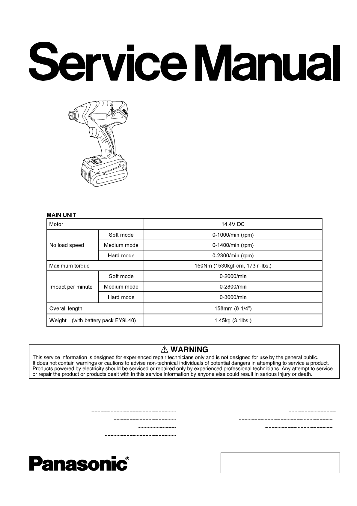
Cordless Impact Driver
EY7540-U1
ORDER NO. PTD0609U42CE
F16
SPECIFICATIONS
CONTENTS
Page Page
1 SCHEMATIC DIAGRAM 2
2 WIRING CONNECTION DIAGRAM
3 DISASSEMBLY/ASSEMBLY INSTRUCTIONS
4 TROUBLESHOOTING GUIDE
5 CHECK PARTS IDENTIFY PROCEDURE 9
2
6 EXPLODED VIEW
7 REPLACEMENT PARTS LIST
3
7
© 2006 Matsushita Electric Works Ltd. All rights
reserved. Unauthorized copying and distribution is a
violation of law.
11
12
Page 2
EY7540-U1 /
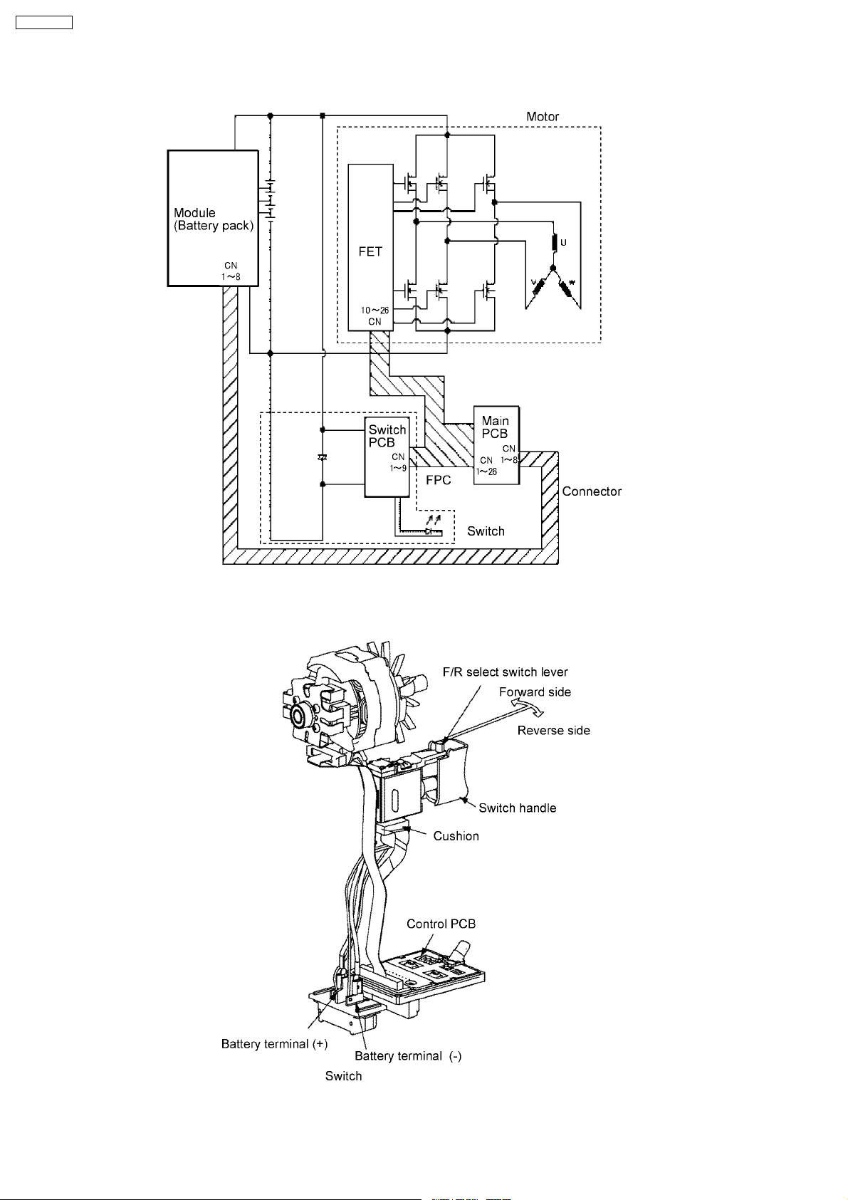
1 SCHEMATIC DIAGRAM
2 WIRING CONNECTION DIAGRAM
2
Page 3
3 DISASSEMBLY/ASSEMBLY INSTRUCTIONS
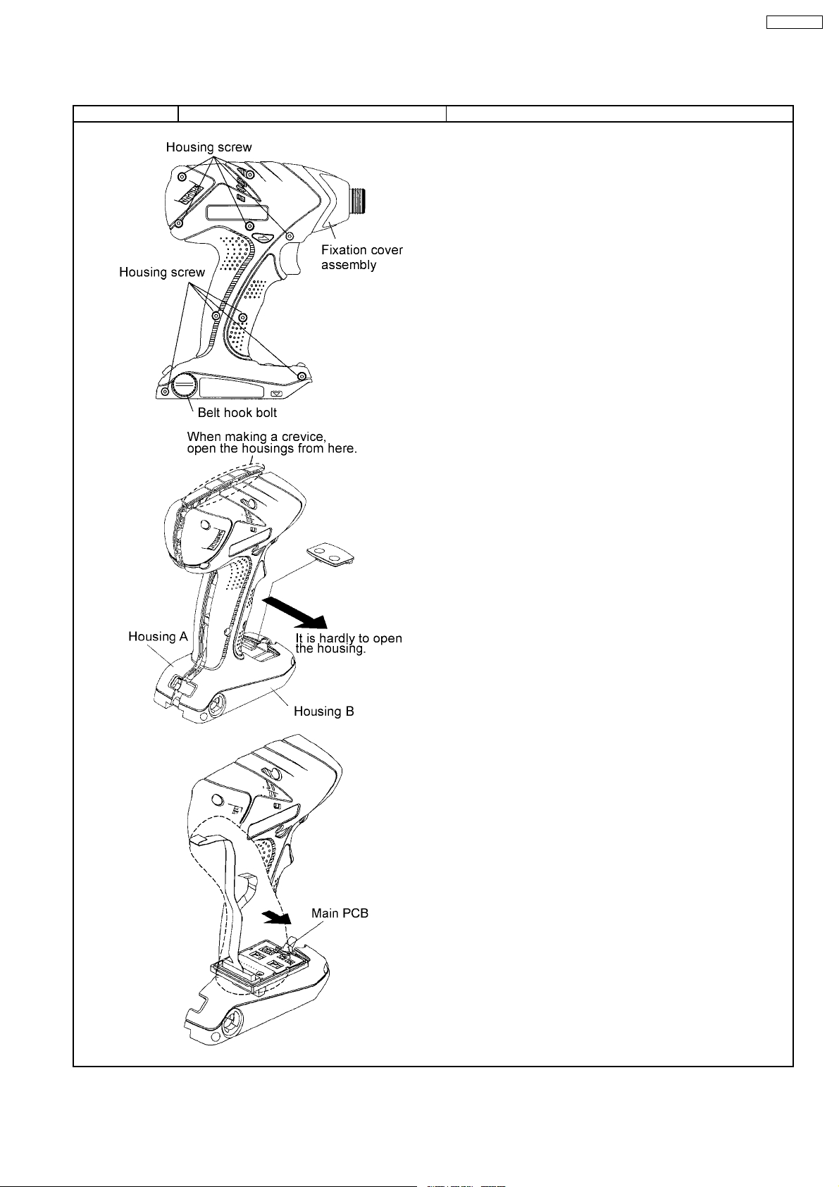
Ref. No. 1A Procedure 1A Removal and attachment of the Housings.
1. Loosen the belt hook bolt turning it counterclockwise, using a
coin or a flat blade screwdriver.
2. Take out the belt hook.
3. Remove nine housing screws.
4. Open the housing B.
NOTE :
The housing A and B is tightened as the motor mounting base
is joint fitting.
Hold the housing B and take it out vertically.
5. Take out the fixation cover, protectors and anvil block.
(Removal)
NOTE :
When opening the housings, make sure that the main PCB is
on the housing A.
If the main PCB sticks in the housing B and pull it out from the
housing A, the ribbon cable may be defected.
EY7540-U1 /
3
Page 4
EY7540-U1 /
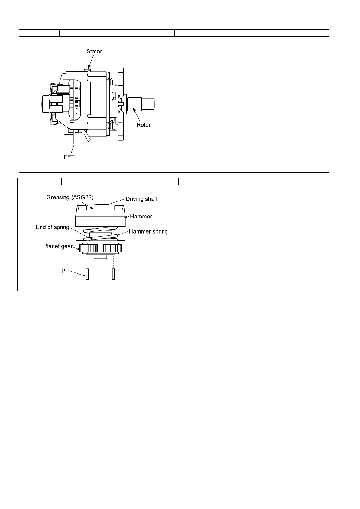
Ref. No. 1B Procedure 1A →→→→ 1B Removal and attachment of the Motor.
(Removal)
1. Take out the motor with the driving block from housing.
2. Separate the motor assembly from the driving block.
3. Take out the motor rotor assembly from the motor stator.
NOTE :
Make sure not to damage the magnet by motor rotor.
(Attachment)
1. Insert the motor rotor assembly into the stator with care of hitching
FET.
NOTE :
Make sure that there is no metal powder around the motor rotor.
Ref. No. 1C Procedure 1A →→→→ 1B →→→→ 1C Removal of the Driving Block.
1. Take out the planet gears and pins slightly tapping the driving
block on the table.
4
Page 5

Ref. No. 1D Procedure 1A →→→→ 1B →→→→ 1C→→→→1D Removal and attachment of the Switch.
1. Take out the switch assembly from the housing.
(Attachment)
1. Connect the motor lead wires.
2. Insert the connectors into the FET, the main PCB and the motor
stator.
NOTE :
Make sure to handle the ribbon cable gently in order to avoid the
breakage.
Apply the grease (FLOIL) on the places where insert into the
connectors.
EY7540-U1 /
5
Page 6

EY7540-U1 /
Ref. No. 1E Procedure 1A →→→→ 1B →→→→ 1C→→→→ 1D→→→→ 1E Assembly of the Driving Block.
1. Press fit the lead wires firmly.
2. Place the ribbon cable properly without getting caught in the lead
wires.
6
Page 7

4 TROUBLESHOOTING GUIDE
(Refer to WIRING CONNECTION DIAGRAM)
EY7540-U1 /
7
Page 8

EY7540-U1 /
8
Page 9

5 CHECK PARTS IDENTIFY PROCEDURE
EY7540-U1 /
9
Page 10

EY7540-U1 /
10
Page 11

6 EXPLODED VIEW
EY7540-U1 /
11
Page 12

EY7540-U1 /
7 REPLACEMENT PARTS LIST
NOTE:
*B=only available as set
*C=available individually
Ref.No. Part No. Part Name & Description Remarks Per Unit
1 WEY7540K3078 HOUSING AB SET 1
2 WEY7540K4058 FIXATION COVER ASSEMBLY 1
3 WEY6507K1166 C-TYPE RING 1
4 WEY6507L0856 THRUST PLATE 1
5 WEY6507L0196 BIT HOLDER SPRING 1
6 WEY7540K3717 BIT HOLDER 1
7 WEY7540K3107 NOSE PROTECTOR 1
8 WEY7540L3137 FIXATION COVER 1
9 WEY6505L0866 SLIDER 1
10 WEY6507L6976 STEEL BALL *B 5/32 (2PCS/PK) 2
11 WEY7540L1128 ANVIL 1
12 WEY7540L1067 DRIVING SHAFT ASSEMBLY 1
13 WEY7201L6966 STEEL BALL *B 7/32 (2PCS/PK) 2
14 WEY7540L1377 HAMMER 1
15 WEY7300L6956 STEEL BALL *B (27PCS/PK) 27
16 WEY6505L0896 THRUST PLATE 1
17 WEY7540L0217 HAMMER SPRING 1
18 WEY6508L1146 SPRING FIXING PLATE 1
19 WEY7540L1137 DRIVING SHAFT 1
20 WEY6504L1357 PLANET GEAR *B (2PCS/PK) 2
21 WEY6506L1346 PIN *B (2PCS/PK) 2
22 WEY7540L0028 MOTOR MOUNTING PLATE ASSEMBLY 1
23 WEY7201L4956 BEARING 1
24 WEY7201L0986 O-RING 1
25 WEY7201L3746 MOTOR MOUNTING PLATE 1
26 WEY7540L1467 MOTOR ROTOR ASSEMBLY 1
27 WEY7540L1187 STATOR 1
28 WEY7540L2108 MODULE ASSEMBLY 1
29 WEY7540L2128 CONTROL PCB 1
30 WEY7540L2067 RIBBON CABLE 1
31 WEY7540K2007 SWITCH ASSEMBLY (SH) 1
32 WEY7540L2157 BATTERY TERMINAL BLOCK 1
33 WEY7540K3217 BELT HOOK SET 1
34 WEY6470K3186 BELT HOOK BOLT 1
35 WEY7540H0407 HOOK RELEASE LEVER 1
36 WEY7540L0167 SPRING FOR RELEASE LEVER 1
37 WEY7540K3338 OPERATION PANEL 1
38 WEY7540H3247 F/R SELECTOR HANDLE 1
39 WEY6230K9216 TORX TAPPING SCREW *C K3-20 9
- WEY9633K7018 TOOL CASE (SH) 1
- WEY7540K8108 OPERATING INSTRUCTIONS (SH) 1
**Battery Pack is available as an optional accessory. See the neares t sales dealer for details.
***For replacement parts of charger, see the charger service manual.
Charger complete set is available as an optional accessory. See the nearest sales dealer for details.
12
 Loading...