

Panasonic EY7540LN2L, EY7540 Operating Instructions Manual
Model No: EY7540
IMPORTANT
This manual contains safety information. Read manual completely before first using this product and save this
manual for future use.
IMPORTANT
Ce mode d’emploi contient des informations sur la sécurité. Lisez-le en entier avant d’utiliser le produit et
conservez-le pour référence.
IMPORTANTE
Este manual contiene información de seguridad. Lea completamente este manual antes de utilizar por primera
vez este producto, y guárdelo para poder consultarlo en el futuro.
Cordless Impact Driver
Perceuse à impact sans l
Destornillador de impacto inalámbrico
Operating Instructions
Instructions d’utilisation
Manual de instrucciones
-
2 -
Index/Index/Indice
English: Page 3 Français: Page 15 Español: Página 30
FUNCTIONAL DESCRIPTION
DESCRIPTION DES FONCTIONS
DESCRIPCIÓN FUNCIONAL
Ni-MH
Ni-Cd
(Q)
(S)
(T)
(F)
(F)
(O)
(N)(M)
(H)
(A)
(B)
(C)
(D)
(E)
(G)
(K)
(P)
(I)
(J)
(L)
(R)
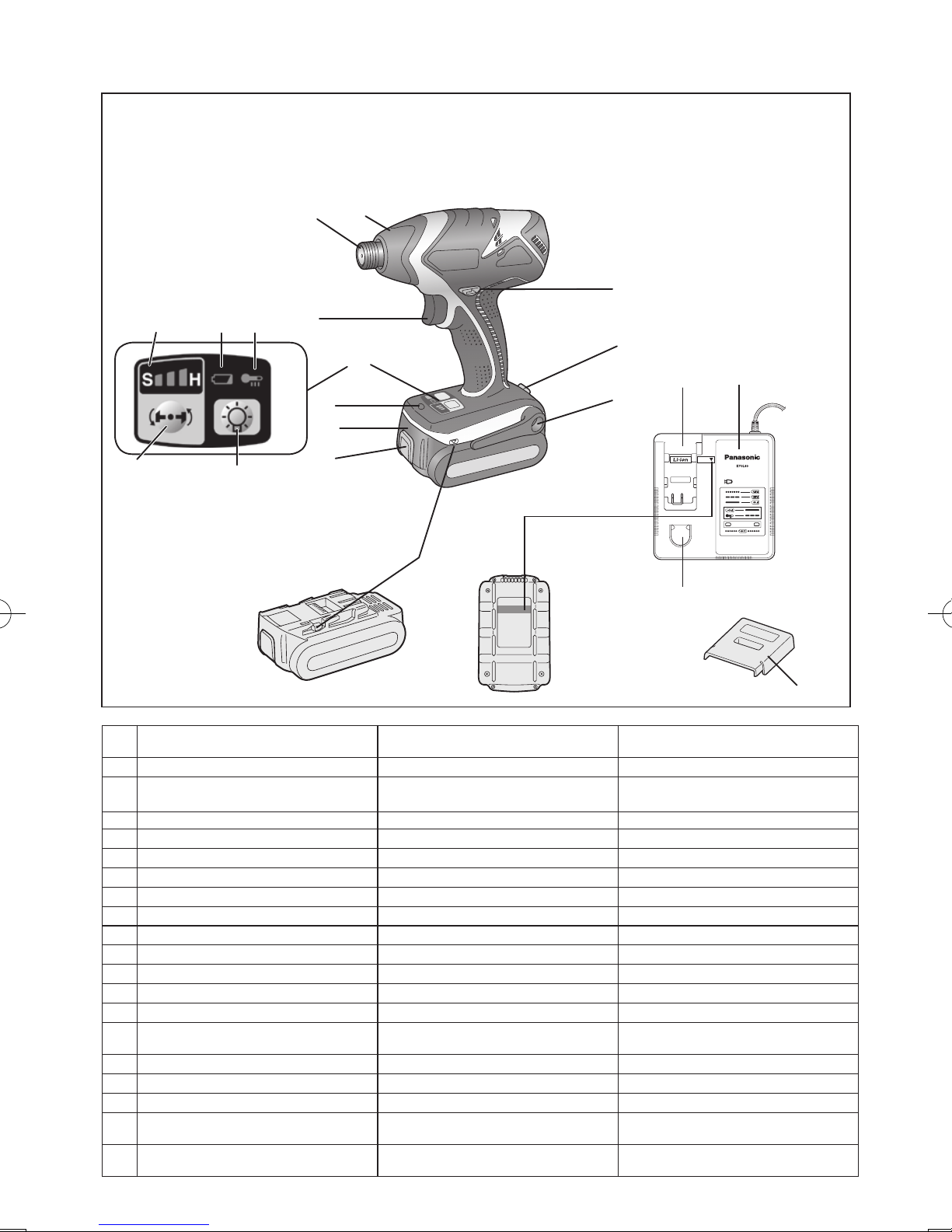
(A) 6.35 mm (1/4") hex quick connect chuck
Mandrin de connexion rapide hexagonal
de 6,35 mm (1/4")
Mandril hexagonal de conexión rápida de
6,35 mm (1/4")
(B) Nose protector Protection du bec Protector del morro
(C) Forward/Reverse lever Levier d’inversion marche avant/
marche arrière
Palanca de avance/marcha atrás
(D) Belt hook lock lever
Levier de verrouillage du crochet de ceinture
Palanca de bloqueo del gancho de cinturón
(E) Belt hook Crochet de ceinture Gancho del cinturón
(F) Alignment marks
Marques d’alignement Marcas de alineación
(G) Battery pack release button
Bouton de libération de batterie autonome
Botón de liberación de batería
(H) Battery pack (EY9L40) Batterie autonome (EY9L40) Batería (EY9L40)
(I) LED light Lumière DEL Luz indicadora
(J) Control panel Panneau de commande Panel de control
(K) LED light on/off button Bouton Marche/Arrêt de la lumière DEL Botón ON/OFF de luz LED
(L) Impact power mode button
Bouton du mode de puissance de percussion
Botón de modo de potencia de impacto
(M) Impact power mode display
Afchage du mode de puissance de percussion
Indicación de modo de potencia de impacto
(N) Battery low warning lamp
Témoin d’avertissement de batterie basse
Luz de aviso de baja carga de batería
(O) Overheat warning lamp (motor/battery) Témoin d’avertissement de surchauffe
(moteur/batterie)
Luz de advertencia de sobrecalentamiento (motor/batería)
(P) Variable speed control trigger Gâchette de commande de vitesse
Disparador del control de velocidad variable
(Q) Battery charger (EY0L80) Chargeur de batterie (EY0L80) Cargador de baterías (EY0L80)
(R) Pack cover Couvercle de la batterie autonome Cubierta de batería
(S) Ni-MH/Ni-Cd battery pack dock Poste d’accueil de la batterie autonome
Ni-MH/Ni-Cd
Enchufe de carga de batería Ni-MH/
Ni-Cd
(T) Li-ion battery pack dock Poste d’accueil de la batterie autonome
Li-ion
Enchufe de carga de batería Li-ión

-
3 -
I
.
GENERAL SAFETY
RULES
WARNING! Read all instructions
Failure to follow all instructions listed
below may result in electric shock, fire
and/or serious injury. The term “power
tool” in all of the warnings listed below
refers to your mains operated (corded)
power tool and battery operated
(cordless) power tool.
SAVE THESE INSTRUCTIONS
Work Area Safety
1) Keep work area clean and well lit.
Cluttered or dark areas invite accidents.
2)
Do not operate power tools in explosive
atmospheres, such as in the presence
of flammable liquids, gases or dust.
Power tools create sparks which may
ignite the dust or fumes.
3)
Keep children and bystanders away
while operating a power tool.
Distractions can cause you to lose control.
Electrical Safety
1) Power tool plugs must match the
outlet. Never modify the plug in any
way. Do not use any adapter plugs
with earthed (grounded) power tools.
Unmodified plugs and matching outlets
will reduce risk of electric shock.
2)
Avoid body contact with earthed or
grounded surfaces such as pipes,
radiators, ranges and refrigerators.
There is an increased risk of electric shock
if your body is earthed or grounded.
3) Do not expose power tools to rain or
wet conditions.
Water entering a power tool will increase
the risk of electric shock.
4)
Do not abuse the cord. Never use
the cord for carrying, pulling or
unplugging the power tool. Keep
cord away from heat, oil, sharp edges
or moving parts.
Damaged or entangled cords increase
the risk of electric shock.
5)
When operating a power tool outdoors,
use an extension cord suitable for
outdoor use.
Use of a cord suitable for outdoor use
reduces the risk of electric shock.
Personal Safety
1)
Stay alert, watch what you are doing
and use common sense when operating
a power tool. Do not use a power tool
while you are tired or under the influence
of drugs, alcohol or medication.
A moment of inattention while operating
power tools may result in personal injury.
2)
Use safety equipment. Always wear
eye protection.
Safety equipment such as dust mask,
non-skid safety shoes, hard hat, or
hearing protection used for appropriate
conditions will reduce personal injuries.
3)
Avoid accidental starting. Ensure the
switch is in the off position before
plugging in.
Carrying power tools with your finger on
the switch or plugging in the power tools
that have the switch on invites accidents.
4)
Remove any adjusting key or wrench
before turning the power tool on.
A wrench or a key left attached to a
rotating part of the power tool may result
in personal injury.
5)
Do not overreach. Keep proper
footing and balance at all times.
This enables better control of the power
tool in unexpected situations.
6)
Dress properly. Do not wear loose
clothing or jewellery. Keep your
hair, clothing and gloves away from
moving parts.
Loose clothes, jewellery or long hair can
be caught in moving parts.
7)
If devices are provided for the
connection of dust extraction and
collection facilities, ensure these are
connected and properly used.
Use of these devices can reduce dust
related hazards.
Power Tool Use and Care
1)
Do not force the power tool. Use the
correct power tool for your application.
The correct power tool will do the job
better and safer at the rate for which it
was designed.
2)
Do not use the power tool if the
switch does not turn it on and off.
Any power tool that cannot be controlled
with the switch is dangerous and must
be repaired.
3)
Disconnect the plug from the power
source and/or the battery pack from

-
4 -
the power tool before making any
adjustments, changing accessories,
or storing power tools.
Such preventive safety measures
reduce the risk of starting the power tool
accidentally.
4)
Store idle power tools out of the reach
of children and do not allow persons
unfamiliar with the power tool or these
instructions to operate the power tool.
Power tools are dangerous in the hands
of untrained users.
5)
Maintain power tools. Check for
misalignment or binding of moving
parts, breakage of parts and any other
condition that may affect the power
tools operation. If damaged, have the
power tool repaired before use.
Many accidents are caused by poorly
maintained power tools.
6)
Keep cutting tools sharp and clean.
Properly maintained cutting tools with
sharp cutting edges are less likely to
bind and are easier to control.
7)
Use the power tool, accessories
and tool bits etc. in accordance with
these instructions and in the manner
intended for the particular type of
power tool, taking into account the
working conditions and the work to
be performed.
Use of the power tool for operations
different from those intended could
result in a hazardous situation.
Battery Tool Use and Care
1) Ensure the switch is in the off position
before inserting battery pack.
Inserting battery pack into power tools
that have the switch on invites accidents.
2)
Recharge only with the charger
specified by the manufacturer.
A charger that is suitable for one type
of battery pack may create a risk of fire
when used with another battery pack.
3)
Use power tools only with specifically
designated battery packs.
Use of any other battery packs may
create a risk of injury and fire.
4)
When battery pack is not in use, keep it
away from other metal objects like paper
clips, coins, keys, nails, screws, or other
small metal objects that can make a
connection from one terminal to another.
Shorting the battery terminals together
may cause burns, or a fire.
5)
Under abusive conditions, liquid may
be ejected from battery; avoid contact.
If contact accidentally occurs, flush
with water. If liquid contacts eyes,
additionally seek medical help.
Liquid ejected from the battery may
cause irritation or burns.
Service
1) Have your power tool serviced by a
qualified repair person using only
identical replacement parts.
This will ensure that the safety of power
tool is maintained.
II
.
SPECIFIC SAFETY
RULES
1) Wear ear protection. Exposure to noise
can cause hearing loss.
2)
Be aware that this tool is always in an
operating condition, since it does not have
to be plugged into an electrical outlet.
3)
Hold power tools by insulated grip-
ping surfaces when performing an
operation where the cutting tool may
contact hidden wiring.
Contact with a “live” wire will make ex-
posed metal parts of the tool “live” and
shock the operator.
4) If the bit becomes jammed, immediately
turn the trigger switch off to prevent an
overload which can damage the battery
pack or motor. Use reverse motion to
loosen jammed bits.
5)
Do NOT operate the Forward/Reverse
lever when the trigger switch is on.
The battery will discharge rapidly and
damage to the unit may occur.
6)
When storing or carrying the tool, set
the Forward/Reverse lever to the center
position (switch lock).
7)
Do not strain the tool by holding the
speed control trigger halfway (speed
control mode) so that the motor stops.
The protection circuit will activate and
may prevent speed control operation. If
this happens, release the speed control
trigger and squeeze again for normal
operation.
8) Be careful not to get dust inside the
chuck.
9) Do not touch the rotating parts to avoid
injury.
-
5 -
10)
Do not use the tool continuously for a long
period of time. Stop using the tool from time
to time to avoid temperature rise and heat
overload of the motor.
11) Do not drop the tool.
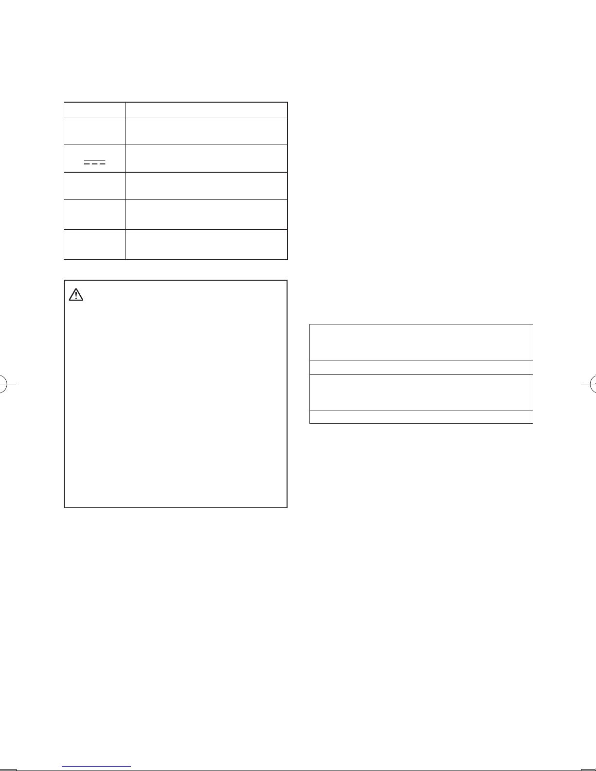
Symbol Meaning
V Volts
Direct current
n
0
No load speed
…/min
Revolutions or reciprocations
per minutes
Ah
Electrical capacity of battery pack
WARNING!
Some dust created by power sanding, sawing,
grinding, drilling, and other construction
activities contains chemicals known to the
State of California to cause cancer, birth
defects or other reproductive harm. Some
examples of these chemicals are:
• Lead from lead-based paints
• Crystalline silica from bricks and
cement and other masonry products
• Arsenic and chromium from chemicallytreated lumber.
To reduce your exposure to these
chemicals: work in a well ventilated area,
and work with approved safety equipment,
such as dust masks that are specially
designed to filter out microscopic particles.
III
.
FOR BATTERY CHARGER
& BATTERY PACK
Important Safety Instructions
1) SAVE THESE INSTRUCTIONS -This
manual contains important safety and
operating instructions for battery charger
EY0L80.
2) Before using battery charger, read all
instructions and cautionary markings
on battery charger, battery pack, and
product using battery pack.
3) CAUTION -To reduce the risk of injury,
charge only Panasonic Battery Pack as
shown in last page.
Other types of batteries may burst
causing personal injury and damage.
4) Do not expose charger and battery pack
to rain or snow.
5) To reduce risk of damaging the electric
plug and cord, pull by plug rather than
cord when disconnecting charger.
6)
Make sure cord is located so that it
will not be stepped on, tripped over, or
otherwise subjected to damage or stress.
7) An extension cord should not be used
unless absolutely necessary.
Use of improper extension cord could
result in a risk of fire and electric shock.
If extension cord must be used, make
sure that:
a. pins on plug of extension cord are
the same number, size and shape as
those of plug on charger.
b. extension cord is properly wired and
in good electrical condition.
c. wire size is large enough for ampere
rating of charger as specified below.
RECOMMENDED MINIMUM AWG SIZE OF
EXTENSION CORDS FOR
BATTERY CHARGERS
AC Input Rating. Amperes
AWG Size of Cord
Equal to or
greater than
But less
than
Length of Cord,
Feet
25 50 100 150
0 2 18 18 18 16
8) Do not operate charger with damaged
cord or plug-replace them immediately.
9) Do not operate charger if it has received
a sharp blow, been dropped, or otherwise damaged in any way; take it to a
qualified service personnel.
10
) Do not disassemble charger; take it
to a qualified service personnel when
service or repair is required. Incorrect
reassembly may result in a risk of
electric shock or fire.
11) To reduce the risk of electric shock,
unplug charger from outlet before
attempting any maintenance or cleaning.
12
)
The charger and battery pack are
specifically designed to work together. Do
not attempt to charge any other cordless
tool or battery pack with this charger.
13) Do not attempt to charge the battery
pack with any other charger.
14) Do not attempt to disassemble the
battery pack housing.
15) Do not store the tool and battery pack
-
6 -
in locations where the temperature
may reach or exceed 50°C (122
°F)
(such as a metal tool shed, or a car
in the summer), which can lead to
deterioration of the storage battery.
16) Do not charge battery pack when the
temperature is BELOW 0°C (32°F)
or ABOVE 40°C (104°F). This is very
important in order to maintain optimal
condition of the battery pack.
17) Do not incinerate the battery pack. It
can explode in a fire.
18) Avoid dangerous environment. Do not
use charger in damp or wet locations.
19) The charger is designed to operate on
standard household electrical power
only. Do not attempt to use it on any
other voltage!
20) Do not abuse cord. Never carry charger
by cord or yank it to disconnect from
outlet. Keep cord away from heat, oil
and sharp edges.
21) Charge the battery pack in a well
ventilated place, do not cover the
charger and battery pack with a cloth,
etc., while charging.
22) Use of an attachment not recommended
may result in a risk of fire, electric
shock, or personal injury.
23) Do not short the battery pack. A battery
short can cause a large current flow,
over heating and create the risk of fire
or personal injury.
24) NOTE: If the supply cord of this
appliance is damaged, it must only be
replaced by a repair shop authorized
by the manufacturer, because special
purpose tools are required.
25)
TO REDUCE THE RISK OF ELECTRIC
SHOCK, THIS APPLIANCE HAS A
POLARIZED PLUG (ONE BLADE IS
WIDER THAN THE OTHER).
This plug will fit in a polarized outlet only
one way. If the plug does not fit fully in
the outlet, reverse the plug. If it still does
not fit, contact a qualified electrician to
install the proper outlet. Do not change
the plug in any way.
IV
. ASSEMBLY
Attaching or Removing Bit
NOTE:
•
When attaching or removing a bit, disconnect battery pack from tool or place the
switch in the center position (switch lock).
1. Hold the collar of quick connect chuck and
pull it out from the driver.
2. Insert the bit into the chuck. Release the
collar.
3. The collar will return to its original position
when it is released.
4.
Pull the bit to make sure it does not come out.
5. To remove the bit, pull out the collar in the
same way.
CAUTION:
• If the collar does not return to its origi-
nal position or the bit comes out when
pulled on, the bit has not been properly
attached. Make sure the bit is properly
attached before use.
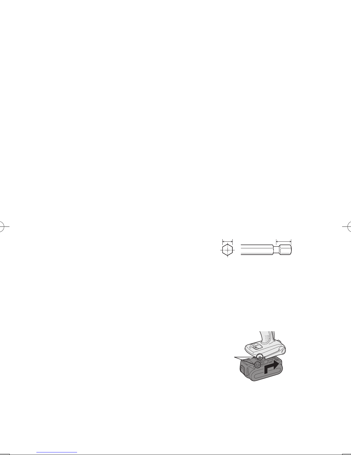
Use 6.35 mm (1/4") hexagonal bits.
To ensure proper securement of the bit,
use only hexagonal bits with 9.5 mm (3/8")
detent.
6.35 mm (1/4")
9.5 mm (3/8")
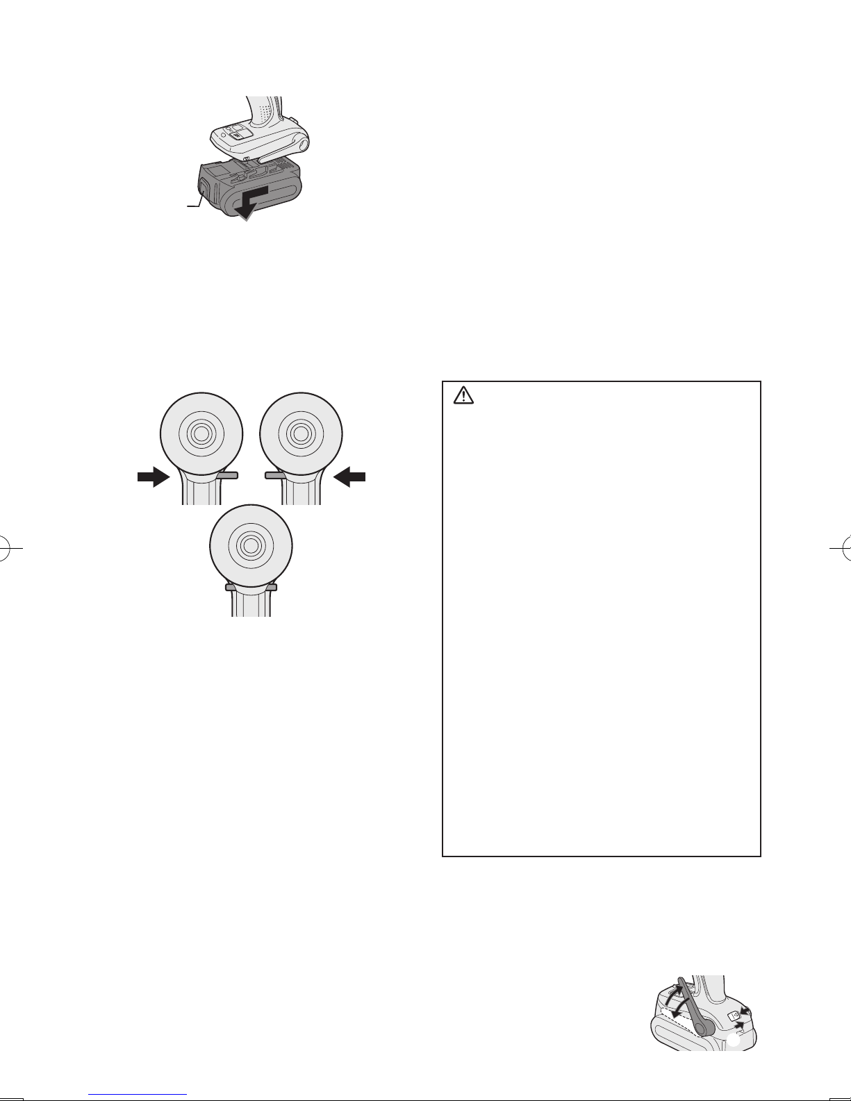
Attaching or Removing Battery Pack
1. To connect the battery pack:
Line up the alignment marks and attach
the battery pack.
•
Slide the battery pack until it locks into
position.
Alignment
marks
-
7 -
2. To remove the battery pack:
Push on the button from the front to release the battery pack.
Button
V
. OPERATION
[Main Body]
Switch and Forward/Reverse
Lever Operation
Forward Reverse
Switch lock
CAUTION:
To prevent damage, do not operate
Forward/Reverse lever until the bit
comes to a complete stop.
Forward Rotation Switch
Operation
1. Push the lever for forward rotation.
2. Depress the trigger switch slightly to start
the tool slowly.
3. The speed increases with the amount of
depression of the trigger for efficient tightening of screws. The brake operates and
the bit stops immediately when the trigger
is released.
4. After use, set the lever to its center posi
-
tion (switch lock).
Reverse Rotation Switch
Operation
1.
Push the lever for reverse rotation. Check
the
direction of rotation before use.
2.
Depress the trigger switch slightly to start the
tool slowly.
3. After use, set the lever to its center position (switch lock).
CAUTION:
• To eliminate excessive temperature
increase of the tool surface, do not
operate the tool continuously using two
or more battery packs. Tool needs cool
off time before switching to another
pack.
How to Use the Belt Hook
WARNING!
• Be sure to attach the belt hook securely to
the main unit with the screw firmly fastened.
When the belt hook is not firmly attached to
the main unit, the hook may disconnect and
the main unit may fall.
This may result in an accident or injury.
• Periodically check screw for tightness. If
found to be loose, tighten firmly.
•
Be sure to attach the belt hook firmly and
securely onto a waist belt or other belt. Pay
attention that the unit does not slip off the
belt.
This may result in an accident or injury.
• When the main unit is held by the belt
hook, avoid jumping or running with it.
Doing so may cause the hook to slip and
the main unit may fall.
This may result in an accident or injury.
• When the belt hook is not used, be sure
to return it to the storing position. The belt
hook may catch on something.
This may result in an accident or injury.
•
When the unit is hooked onto the waist belt
by the belt hook, do not attach driver bits to
the unit. A sharp edge object, such as a drill
bit, may cause injury or an accident.
To Set the Belt Hook Angle
Position
1. Slide the belt hook lock lever 1 and hold
it to unlock the belt hook.
2
1
3
2. Pull the belt hook from
storing position 2 and
set it.
-
8 -
3.
Release the belt hook lock lever to
lock the
angle of belt hook.
4.
Make sure the belt hook is firmly locked.
Also make sure the belt hook is firmly
locked into position 3.
• The belt hook cannot
be locked in this position. Firmly lock it into
position before use.
To return the belt hook to the storing position,
Follow step 1. and 2. above, then lower the
belt hook.
To secure the lock, follow 3 and 4 above.
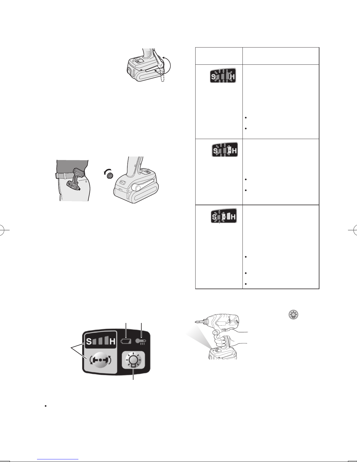
To Change the Belt Hook
Location Side
The belt hook can be attached to either
side of the unit.
1. Set the belt hook at storing position.
2. Loosen the screw turning it counterclockwise, using a flat metal or a flat
blade screw driver.
3. Take out the belt hook and insert into
the other side of the slot on the main
unit.
4. Fasten the screw firmly, turning it clock
-
wise.
The belt hook can be taken out from the
main unit only when it is at storing position.
Control Panel
(1)
(2)
(4) (3)
(1) Impact Power Mode Select
Selecting the impact power among 3
modes (Soft, Medium, Hard).
Press the impact power mode button to set
it. The mode changes to hard, medium, or
soft each time the button is pressed.
The driver is preset to “hard” impact mode
setting when shipped from the manufacturer.
Recommended work guideline table
Impact
Power mode
Display
Recommended Application
H
Jobs requiring a high level
of torque where there is
no possibility of the screw
breaking, its top shearing off,
or the bit coming loose. (This
setting provides maximum
torque.) Suitable applications
include:
Tightening M8 and larger
bolts
Tightening long screws
during interior finishing work
0 - 2300 r.p.m.
and
0 - 3000 i.p.m.
M
Jobs requiring limited torque
where there is a possibility of
the screw breaking or its top
shearing off. (This setting limits
torque.) Suitable applications
include:
Tightening bolts with
smaller diameters (M6)
Tightening metalwork
screws when installing
fixtures
0 - 1400 r.p.m.
and
0 - 2800 i.p.m.
S
Jobs requiring limited torque
where there is a possibility
of the screw breaking, its
top shearing off, or the bit
coming loose and damaging
a nished exterior surface.
(This setting limits torque.)
Suitable applications include:
Tightening bolts smaller
than M6 that may shear
easily
Tightening screws into
molded plastic
Installing gypsum wallboard
0 - 1000 r.p.m.
and
0 - 2000 i.p.m.
* i.p.m. = Impact per minute.
(2) LED light
Pressing the button
toggles the LED light on
and off.
The light illuminates with
very low current, and
it does not adversely
affect the performance
of the
driver during use
or its battery capacity.
CAUTION:
• The built-in LED light is designed to illuminate the small work area temporarily.
•
Do not use it as a substitute for a regular
flashlight, since it does not have
enough brightness
.
This product has the built-in LED light.
-
9 -
This product is classified into “Class 1 LED
Product” to EN 60825-1
Class 1 LED Product
Caution : DO NOT STARE INTO BEAM.
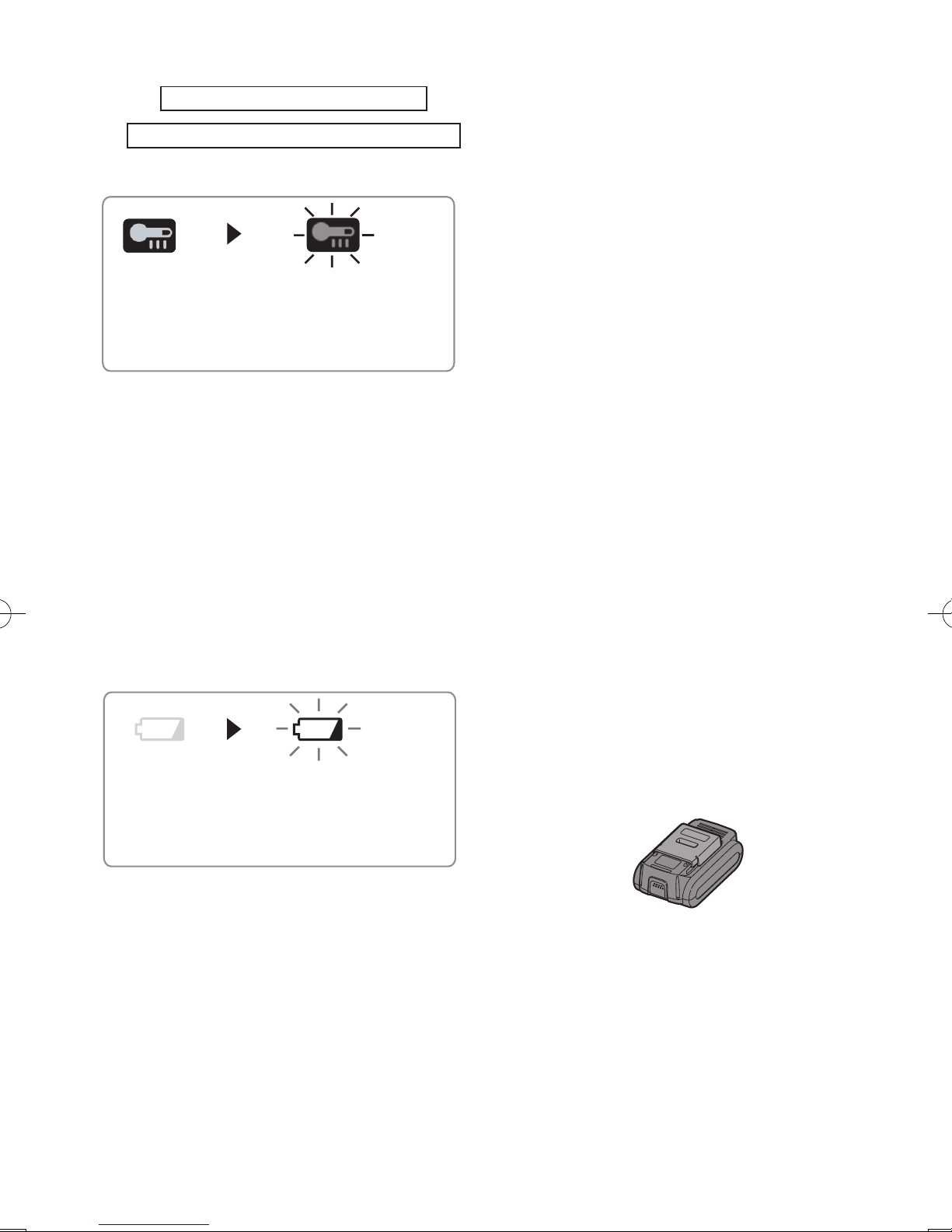
(3)
Overheat warning lamp
Off (normal
operation)
Flashing: Overheat
Indicates operation has
been halted due to motor
or battery overheating.
The overheating protection feature halts
driver operation to protect the motor and
battery pack in the event of overheating.
The overheat warning lamp on the control
panel flashes when this feature is active.
•
If the overheating protection feature activates, allow the driver to cool thoroughly
(at least 30 minutes). The driver is ready
for use when the overheat warning lamp
goes out.
•
Avoid using the driver in a way that
causes the overheating protection feature to activate repeatedly.
(4) Battery low warning lamp
Off (normal
operation)
Flashing (No charge)
Battery protection
feature active
Excessive (complete) discharging of
lithium ion batteries shortens their service
life dramatically. The driver includes a
battery protection feature designed to
prevent excessive discharging of the
battery pack.
• The battery protection feature activates
immediately before the battery loses its
charge, causing the battery low warning
lamp to flash.
• If you notice the battery low warning
lamp flashing, charge the battery pack
immediately.
Recommended Grip
Use the grip to hold and operate the
driver with one hand. If the job requires
additional force, you can push against
the rear end of the driver with your other
hand.
[Battery Pack]
For Appropriate Use of Bat-
tery Pack
Li-ion Battery Pack (EY9L40)
• For optimum battery life, store the Li-ion
battery pack following use without charging it.
• The ambient temperature range is
between 0°C (32°F) and 40°C (104°F).
If the battery pack is used when the battery
temperature is below 0°C (32°F), the tool
may fail to function properly.
• When battery pack is not in use, keep it
away from other metal objects like: paper
clips, coins, keys, nails, screws, or other
small metal objects that can make a connection from one terminal to another.
Shorting the battery terminals together
may cause sparks, burns or a fire.
• When operating the battery pack, make
sure the work place is well ventilated.
• When the battery pack is removed from
the main body of the tool, replace the
battery pack cover immediately in order
to prevent dust or dirt from contaminating
the battery terminals and causing a short
circuit.
Battery Pack Life
The rechargeable batteries have a limited life. If the operation time becomes
extremely short after recharging, replace
the battery pack with a new one.

-
10 -
Battery Recycling
ATTENTION:
FOR Li-ion Battery Pack, EY9L40
A Li-ion battery that is recyclable powers the
product you have purchased. Please call 1-800-
8-BATTERY for information on how to recycle
this battery.
[Battery Charger]
Charging
Common Cautions for the Liion/Ni-MH/Ni-Cd Battery Pack
NOTE:
• When charging a cool battery pack
(below 0°C (32°F)) in a warm place,
leave the battery pack at the place and
wait for more than one hour to warm up
the battery to the level of the ambient
temperature. Otherwise battery pack
may not be fully charged.
•
Cool down the charger when charging
more than two battery packs consecutively.
• Do not insert your fingers into contact
hole, when holding charger or any other
occasions.
CAUTION:
To prevent the risk of fire or damage to
the battery charger.
• Do not use power source from an
engine generator.
• Do not cover vent holes on the charger
and the battery pack.
• Unplug the charger when not in use.
Li-ion Battery Pack
NOTE:
Your battery pack is not fully charged at
the time of purchase. Be sure to charge
the battery before use.
Battery charger (EY0L80)
1. Plug the charger into the AC outlet.
NOTE:
Sparks may be produced when the plug
is inserted into the AC power supply, but
this is not a problem in terms of safety.
2.
Insert the battery pack firmly into the charger.
1 Line up the alignment marks and place the
battery onto the dock on the charger.
2 Slide forward in the direction of the arrow.
Alignment marks
3.
During charging, the charging lamp will be
lit.
When charging is completed, an internal
electronic switch will automatically be triggered to prevent overcharging.
• Charging will not start if the battery
pack is warm (for example, immediately
after heavy-duty operation).
The orange standby lamp will be flash-
ing until the battery cools down.
Charging will then begin automatically.
4. The charge lamp (green) will flash slowly
once the battery is approximately 80%
charged.
5.
When charging is completed, the charging
lamp will start flashing quickly in green color.
6. If the temperature of the batter pack is
0°C or less, charging takes longer to fully
charge the battery pack than the standard
charging time.
Even when the battery is fully charged, it
will have approximately 50% of the power
of a fully charged battery at normal operating temperature.
7.
If the power lamp does not light immediately
after the charger is plugged in, or if after the
standard charging time the charging lamp
does not flash quickly in green, consult an
authorized dealer.
8. If a fully charged battery pack is inserted
into the charger again, the charging lamp
lights up. After several minutes, the charging lamp may flash quickly to indicate the
charging is completed.
Ni-MH/Ni-Cd Battery Pack
NOTE:
When you charge the battery pack for
the first time, or after prolonged storage, charge it for about 24 hours to
bring the battery up to full capacity.
-
11 -
Battery charger (EY0L80)
1. Plug the charger into the AC outlet.
NOTE:
Sparks may be produced when the plug
is inserted into the AC power supply, but
this is not a problem in terms of safety.
2.
Insert the battery pack firmly into the charger.
3.
During charging, the charging lamp will be
lit.
When charging is completed, an internal
electronic switch will automatically be triggered to prevent overcharging.
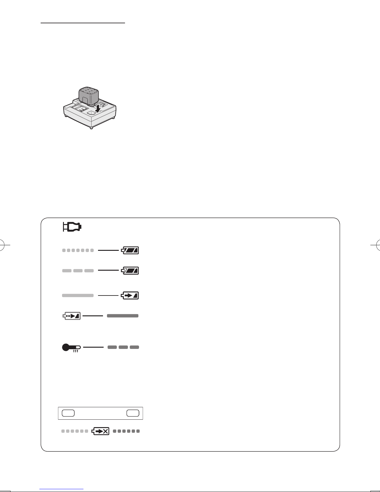
LAMP INDICATIONS
Green Lit
Charger is plugged into the AC outlet.
Ready to charge.
Green Flashing Quickly
Charging is completed. (Full charge.)
Green Flashing
Battery is approximately 80% charged (Usable charge. Li-ion
only).
Green Lit
Now charging
Orange Lit
Battery pack is cool.
The battery pack is being charged slowly to reduce the load on
the battery. (Li-ion only)
Orange Flashing
Battery pack is warm. Charging will begin when temperature
of battery pack drops.
If the temperature of the battery pack is -10°C or less,
the charging status lamp (orange) will also start ashing.
Charging will begin when the temperature of the battery
pack goes up (Li-ion only).
Charging Status Lamp
Left: green Right: orange will be displayed.
Both Orange and Green Flashing Quickly
Charging is not possible. Clogged with dust or malfunction of
the battery pack.
• Charging will not start if the battery
pack is warm (for example, immediately after heavy-duty operation).
The orange standby lamp will be
flashing until the battery cools down.
Charging will then begin automatically.
4.
When charging is completed, the charging lamp will start flashing quickly in green
color.
5.
If the charging lamp does not light immediately after the charger is plugged in, or if
after the standard charging time the charging lamp does not flash quickly in green,
consult an authorized dealer.
6. If a fully charged battery pack is inserted into the charger again, the charging
lamp lights up. After several minutes, the
charging lamp may flash quickly to indicate the charging is completed.
-
12 -
VI
. MAINTENANCE
Use only a dry, soft cloth for wiping the unit.
Do not use a damp cloth, thinner, benzine,
or other volatile solvents for cleaning.
VII
. TIGHTENING
TORQUE
The power required for tightening a bolt will
vary, according to bolt material and size, as
well as the material being bolted. Choose
the length of tightening time accordingly.
Reference values are provided below.
(They may vary according to tightening conditions.)
Factors Affecting Tightening Torque
The tightening torque is affected by a wide
variety of factors including the followings.
After tightening, always check the torque
with a torque wrench.
1) Voltage
When the battery pack becomes near-
ly discharged, the voltage decreases and
the tightening torque drops.
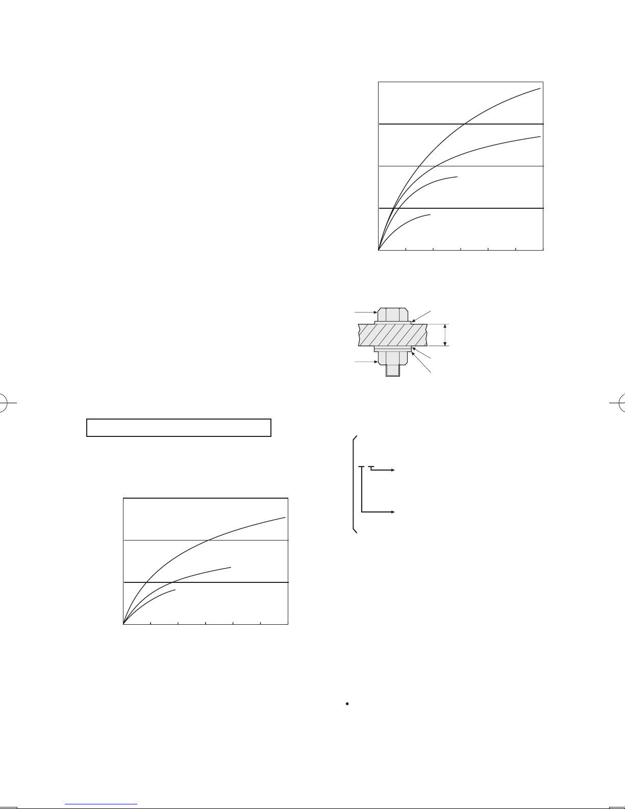
Bolt Tightening Conditions
0.50.0 1.0 1.5 2.0 3.02.5
M10
M8
M12
N ⋅ m
(kgf-cm)
49.0
(500)
98.0
(1000)
147.0
(1500)
Tightening torque
Tightening time (Sec.)
M8, M10 x 35 mm. M12 x 45 mm
High tensile bolt
(Bolt size: Millimeters)
0.50.0 1.0 1.5 2.0 3.02.5
M16
M12
M14
M10
49.0
(500)
98.0
(1000)
147.0
(1500)
196.0
(2000)
N ⋅ m
(kgf-cm)
Tightening torque
Tightening time (Sec.)
M10 x 35 mm. M12, M14, M16 x 45 mm
Standard bolt
Bolt
Nut
Washer
Steel plate
thickness10 mm (3/8")
Washer
Spring washer
Tightening conditions
• The following bolts are used.
Standard bolts: Strength type 4.8
High tensile type 12.9
4.8
Explanation of the strength type
Bolt yield point
(80% of tensile strength)
32 kgf/mm2 (45000psi)
Bolt tensile strength
40 kgf/mm2 (56000psi)
2) Tightening time
Longer tightening time results in increased
tightening torque. Excessive tightening,
however, adds no value and reduces the
life of the tool.
3) Different bolt diameters
The size of the bolt diameter affects the
tightening torque.
Generally, as the bolt diameter increases,
tightening torque rises.
4) Tightening conditions
Tightening torque will vary, even with the
same bolt, according to grade, length, and
torque coefficient (the fixed coefficient indicated by the manufacturer upon production).

-
13 -
Tightening torque will vary, even with the
same bolting material (e.g. steel), according to the surface finish.
Torque is greatly reduced when the bolt
and nut start turning together.
5) Socket play
Torque is lowered as the six-sided configu-
ration of the socket of the wrong size is
used to tighten a bolt.
6) Switch (Variable speed control trigger)
Torque is lowered if the unit is used with
the switch not fully depressed.
7) Effect of Connecting Adaptor
The tightening torque will be lowered
through the use of a universal joint or a
connecting adaptor.
VIII
. ACCESSORIES
Use only bits suitable for size of chuck.
IX
. APPENDIX
MAXIMUM RECOMMENDED CAPACITIES
Model
EY7540
Screw driving
Wood screw
3.5 - 9.5 mm (1/8" - 3/8")
Self-drilling screw
3.5 - 6 mm (1/8" - 1/4")
Bolt fastening
Standard bolt : M6 - M16
High tensile bolt
: M6 - M12
X
. SPECIFICATIONS
MAIN UNIT
Model EY7540
Motor 14.4 V DC
No load speed
soft mode 0 - 1000 /min (rpm)
medium mode 0 - 1400 /min (rpm)
hard mode 0 - 2300 /min (rpm)
Maximum torque 150 N·m (1530 kgf-cm, 173 in-lbs.)
Impact per minute
soft mode 0 - 2000 /min (ipm)
medium mode 0 - 2800 /min (ipm)
hard mode 0 - 3000 /min (ipm)
Overall length 158 mm (6-1/4")
Weight (with battery pack : EY9L40) 1.45 kg (3.1 lbs)
BATTERY PACK
Model EY9L40
Storage battery Li-ion Battery
Battery voltage 14.4 V DC (3.6 V x 4 cells)
Capacity 3 Ah
-
14 -
BATTERY CHARGER
Model EY0L80
Rating See the rating plate on the bottom of the charger.
Weight 0.95 kg (2.1 lbs)
[Li-ion battery pack]
Charging time
14.4 V
3 Ah
EY9L40
Usable: 35 min.
Full: 50 min.
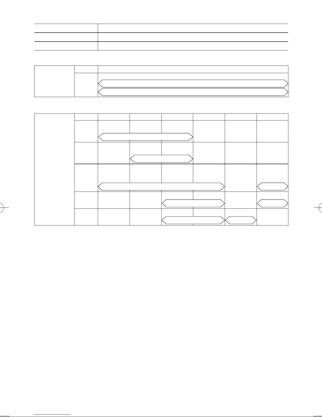
[Ni-Cd/Ni-MH battery pack]
Charging time
7.2 V
9.6 V 12 V 15.6 V 18 V 24 V
1.2 Ah
EY9065
EY9066
EY9080
EY9086
EY9001
20 min.
1.7 Ah
EY9180
EY9182
EY9101
EY9103
25 min.
2 Ah
EY9168 EY9188
EY9106
EY9107
EY9108
EY9136
EY9116
EY9117
30 min.
60 min.
3 Ah
EY9200 EY9230 EY9210
45 min. 90 min.
3.5 Ah
EY9201 EY9231 EY9251
55 min. 65 min.
NOTE: This chart may include models that are not available in your area.
Please refer to the latest catalogue
.

-
15 -
I.
CONSIGNES DE SECURITE GENERALES
AVERTISSEMENT! Veuillez lire tou-
tes les instructions.
Si les instructions détaillées ci-dessous ne
sont pas observées, cela peut entraîner une
électrocution, un incendie et/ou des blessures
graves. Le terme “outil mécanique” utilisé dans
tous les avertissements ci-dessous se réfère
aux outils mécaniques opérés par cordons
d'alimentation et par batterie (sans l).
CONSERVEZ CES INSTRUCTIONS
Sécurité de la zone de travail
1) Gardez la zone de travail propre et
bien aérée.
Les endroits encombrés et sombres invitent les accidents.
2)
Ne faites pas fonctionner les outils
mécaniques dans des atmosphères
explosives, comme en présence de
liquides inflammables, de gaz ou de
poussière.
Les outils mécaniques génèrent des étincelles qui peuvent enflammer la poussière ou les vapeurs.
3)
Gardez les enfants et les spectateurs
éloignés lors du fonctionnement d’un
outil mécanique.
Les distractions peuvent en faire perdre le
contrôle.
Sécurité électrique
1) La fiche des outils mécaniques doit
correspondre aux prises secteur. Ne
modifiez la fiche sous aucun prétexte.
N’utilisez pas de fiche adaptatrice
avec les outils mécaniques mis à la
terre.
Des fiches non modifiées et des prises
secteur correspondant réduisent les
risques d’électrocution.
2)
Evitez tout contact physique avec les
surfaces mises à la terre telles que
tuyaux, radiateurs, micro-ondes et
réfrigérateurs.
Il y a un risque d’électrocution supplémentaire si votre corps est mis à la terre.
3) N’exposez pas les outils mécaniques à
la pluie ou à des conditions humides.
De l’eau pénétrant dans un outil mécanique augmente le risque d’électrocution.
4)
Ne malmenez pas le cordon. N’utilisez
jamais le cordon pour transporter,
pour tirer ou pour débrancher l’outil
mécanique. Gardez le cordon éloigné
de la chaleur, de l’huile, d’objets aux
bords coupants ou de pièces en
mouvement.
Les cordons endommagés on emmêlés
augmentent le risque d'électrocution.
5)
Lors du fonctionnement des outils mécaniques à l’extérieur, utilisez une rallonge
adaptée à l’utilisation à l’extérieur.
L’utilisation d’un cordon adapté à l’utilisation à l’extérieur réduit les risques d’électrocution.
Sécurité personnelle
1) Restez alerte, regardez ce que vous
faites et faites preuve de bon sens
lorsque vous utilisez un outil mécanique. N’utilisez pas un outil mécanique alors que vous êtes fatigué ou
sous les effets de drogue, d’alcool ou
de médicaments.
Un moment d’inattention pendant que
vous faites fonctionner l’outil mécanique
peut entraîner des blessures graves.
2)
Utilisez des équipements de sécurité.
Portez toujours des protection pour
vos yeux.
Des équipements de sécurité comme
masque antipoussière, chaussures
de sécurité non glissantes, casque de
protection ou protections d’oreilles,
utilisés dans des conditions appropriées
réduisent les blessures corporelles.
3)
Evitez tout démarrage accidentel.
Assurez-vous que l
’interrupteur est
en position d'arrêt avant de brancher
l’outil.
Le transport d’outils mécaniques avec le
doigt sur l’interrupteur ou le branchement
d’outils mécaniques dont l’interrupteur
est sur la position de marche invite les
accidents.
4)
Retirez toute clé d’ajustement ou
clé de serrage avant de mettre l’outil
mécanique en marche.
Une clé de serrage ou une clé d’ajustement laissée attachée à une pièce
tournante de l’outil mécanique peut
entraîner des blessures corporelles.
5)
Ne vous mettez pas en déséquilibre.
Gardez une bonne prise au sol et votre
équilibre à tout moment.
Ceci permet un meilleur contrôle de l’outil
mécanique dans des situations inattendues.
 Loading...