

Panasonic EY7530 Service Manual
ORDER NO. PTD1408E44CE
TABLE OF CONTENTS
Impact driver
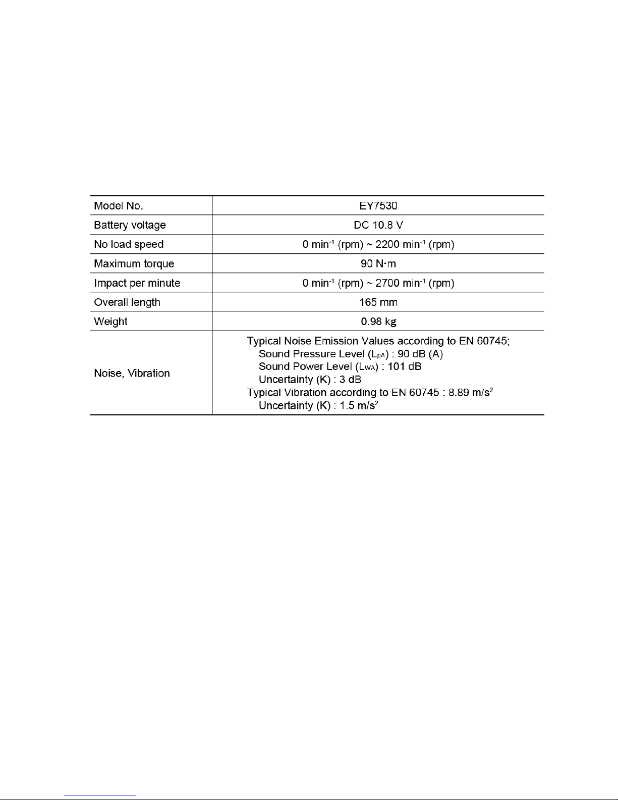
Model No. EY7530
Europe
Panasonic corporation 2014.
All rights reserved. Unauthorized copying and distribution
is a violation of law.
PAGE
1. Warning 2
2. Specifications 2
3. Troubleshooting Guide 3
4. Disassembly and Assembly Instructions 6
5. Wiring Connection Diagram 10
6. Schematic Diagram 10
7. Exploded View and Replacement Parts List 11
2
2.1 Main Unit
2 Specifications
1 Warning
Caution:
• Pb free solder has a higher melting point that standard solder; Typically the melting point is 50 - 70°F (30 -
40°C) higher. Please use a soldering iron with temperature control and adjust it to 750 ± 20°F (400 ±
10°C). In case of using high temperature soldering iron, please be careful not to heat too long.
• Pb free solder will tend to splash when heated too high (about 1100°F / 600°C).
NOTE: Weight indication
Greater than or equal to 1kg : indicated by 0.05kg.
Less than 1kg : indicated by 0.01kg.
3
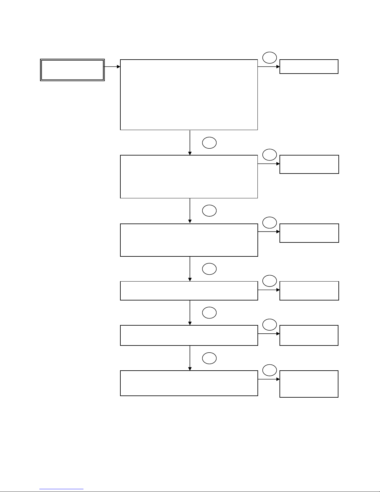
《TROUBLE》 《CHECK》 《REMEDY》
3 Troubleshooting Guide
NO
OK
3.1 Troubleshooting Guide
Does not operate
(spin)
Replace battery pack.
<CHECK BATTERY PACK>
If no less than 10.8V DC is available across the (+)
and (-) terminals, the battery pack is OK.
Note: The battery pack is sold separately as an
optional accessory. See the nearest sales dealer
for details. The battery pack has a limited life.
The pack should be replaced if
- after being charged for the rated charging time
the battery voltage is less than 10.8V or the
usable time is extremely short.
Replace motor and
PCB block.
<CHECK MOTOR AND PCB BLOCK>
After attaching the battery pack, removing the tool
housing, and removing the motor and gear case block,
pull the trigger and check whether the motor operates.
<CHECK TERMINAL CONNECTIONS BETWEEN
MAIN UNIT AND BATTERY PACK>
• There are no much gull.
• Terminal connections are not blackened and allow
conduction.
• Terminal connections are not rusty or deformed.
Replace motor and
PCB block.
<CHECK MOTOR PINION>
Verify that the pinion is not cracked.
Replace motor and
PCB block.
<CHECK LEAD WIRE>
Check if there is no breakage of lead wires.
Replace motor and
PCB block.
NO
OK
NO
OK
NO
OK
NO
Replace spindle
block or hammer
block.
<CHECK DRIVING BLOCK>
Check whether the motor operates after attaching the
spindle block and hammer block
OK
NO
4
《TROUBLE》 《CHECK》 《REMEDY》
NO
OK
NO
Cannot be
controlled
Replace motor and
PCB block.
<CHECK THE SPEED CONTROL>
Pull back on the switch trigger gradually and check
whether the tool’s speed increases smoothly.
<CHECK LED LIGHT>
Check if LED lights on when pulling the trigger.
Replace motor and
PCB block.
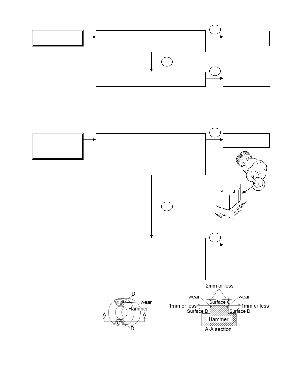
《TROUBLE》 《CHECK》 《REMEDY》
NO
Replace hammer
block
Replace motor and
PCB block.
The tool is not
producing
adequate impact
force.
<Check anvil>
Check the amount of wear on the anvil.
Wear is within acceptable bounds if wear in the area of
contact with the output shaft and hammer is limited to
an area 1mm or less from the corner on surface A and
an area 0.5mm or less from the corner on surface B.
(See figure 1.)
<Check the driving shaft assembly>
・ Check the amount of wear on the hammer. Wear is
within acceptable bounds if wear in the area of
contact with the output shaft and hammer is limited to
an area 2mm or less from the corner on surface C
and an area 1mm or less from the corner on surface
D. (See figure 2.)
OK
NO
Fig. 1
Fig. 2
 Loading...