

Panasonic ERA 2A, ERA 3A, ERA 6A, ERA 8A Technical data
a
b
t
W
L
Metal Film Chip Resistors,
High Reliability Type
0402, 0603, 0805, 1206
Typ e:
ERA 2A, 3A, 6A, 8A
Metal Film Chip Resistors, High Reliability Type
■ Features
High reliability
●
(85 °C 85 %RH rated load, Category temperature range : –55 to +155 °C)
High accuracy
●
High performance
●
Reference Standard
●
...............
..............
.........
......
Stable at high temperature and humidity
Small resistance tolerance and Temperature Coeffi cient of Resistance
Low current noise, excellent non-linearity
IEC 60115-8, JIS C 5201-8, EIAJ RC-2133A
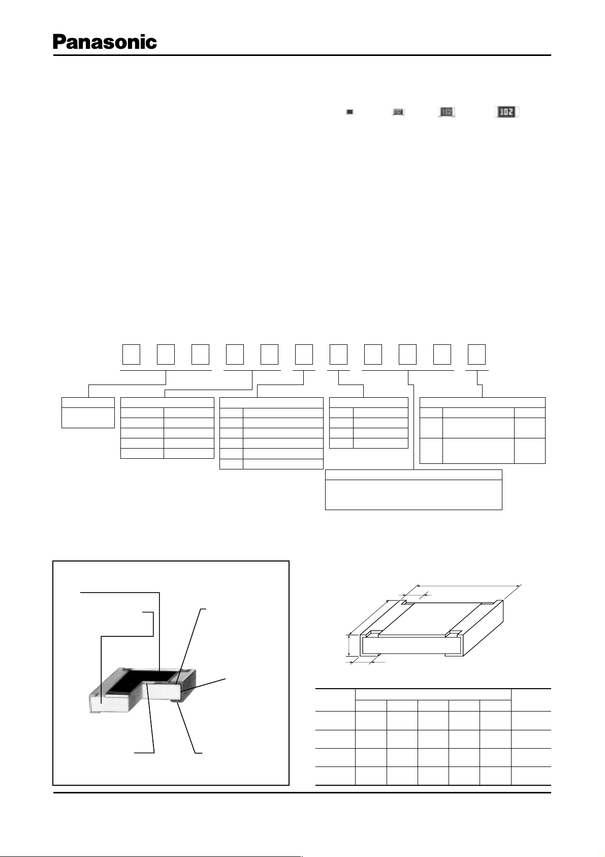
■ Explanation of Part Numbers
1
E
Product Code Size, Power Rating
Metal Film
Chip Resistors
Type: inches Power Rating
2A : 0402
3A : 0603
6A : 0805
8A : 1206
2
R
0.063 W
0.1 W
0.125 W
0.25 W
3
A
4
3
Temperature Coefficient
Code
R
P
E
H
K
A
±1010
±1510
±2510
±5010
±10010
5
T.C.R.
–6
/°C (ppm/°C)
–6
/°C (ppm/°C)
–6
/°C (ppm/°C)
–6
/°C (ppm/°C)
–6
/°C (ppm/°C)
6
E
7
B
Resistance Tolerance
Code
W
B
D
The first two digits are significant figures of resistance
and the third one denotes number of zeros following.
(ex.) 102:1k
8
1
Tolerance
±0.05 %
±0.1 %
±0.5 %
Resistance Value
9
0
Code
X
V
10
2
Packaging Methods
Punched Carrier
Taping (2 mm pitch)
Punched Carrier
Taping (4 mm pitch)
11
V
Packaging Type
ERA2A
ERA3A
ERA6A
ERA8A
■ Dimensions in mm (not to scale)■ Construction
Protective coating
Alumina substrate
High reliability
metal film
Design and specifi cations are each subject to change without notice. Ask factory for the current technical specifi cations before purchase and/or use.
Should a safety concern arise regarding this product, please be sure to contact us immediately.
Electrode (Inner)
Electrode
(Between)
Electrode (Outer)
Type
(inches)
ERA2A
(0402)
ERA3A
(0603)
ERA6A
(0805)
ERA8A
(1206 )
Dimensions (mm)
LWa b t
1.00
1.60
2.00
3.20
±0.10
±0.20
±0.20
±0.20
0.50
0.80
1.25
1.60
+0.10
–0.05
±0.20
±0.10
±0.10
0.15
0.30
0.40
0.50
±0.10
±0.20
±0.25
±0.25
0.25
0.30
0.40
0.50
±0.10
±0.20
±0.25
±0.25
0.35
0.45
0.50
0.60
Mass (Weight)
[g/1000 pcs.]
±0.05
±0.10
±0.10
±0.10
Mar. 2009
0.6
2
4
8
Metal Film Chip Resistors, High Reliability Type
■ Ratings
Power
Typ e
(inches)
Rating
at 85 °C
(W)
ERA2A
(0402)
ERA3A
(0603)
ERA6A
(0805)
ERA8A
(1206 )
(1) Rated Co ntinuous Working Voltage (RCWV) shall be de ter mined from RCWV=Rated Power Re sis tance Values, or Limiting Element Voltage
(max. RCWV) list ed above, whichever less.
(2) Overload (Short-time Overload) Test Voltage (SOTV) shall be de termined from SOTV=2.5 Power Rating or max. Over load Volt age list ed above
which ev er less.
(3) E96 series resistance values are also available. Please contact us for details.
0.063 25 50
0.1 75 150
0.125 100 200
0.25 150 300
Limiting Element
Voltage (Maximum
(1)
RCWV)
(V)
Maximum
Overload
Voltage
(V)
(2)
Typ e
(detail)
Resistance
Tol e rance
(%)
ERA2AKD ±0.5 ±100
ERA2AED ±0.5
ERA2AEB ±0.1
ERA3AHD ±0.5 ±50
ERA3AED ±0.5
ERA3AEB ±0.1
ERA6AHD ±0.5 ±50
ERA6AED ±0.5
ERA6AEB ±0.1
ERA6APB ±0.1 ±15
ERA6ARB ±0.1
ERA6ARW ±0.05
ERA8AHD ±0.5 ±50
ERA8AED ±0.5
ERA8AEB ±0.1
T.C.R .
–6
/°C
[10
(ppm/ °C)]
±25
±25
±25
±10
±25
Resistance
Range
(3)
()
10 to 43 (E24)
47 to 100 k (E24)
10 to 43 (E24)
47 to 330 k (E24)
10 to 43 (E24)
47 to 1 M (E24)
470 to 100 k (E24)
1 k to 100 k (E24)
10 to 43 (E24)
47 to 1 M (E24)
Category Temperature
Range (Operating
Temp e r ature R a n g e)
(°C)
–55 to +155
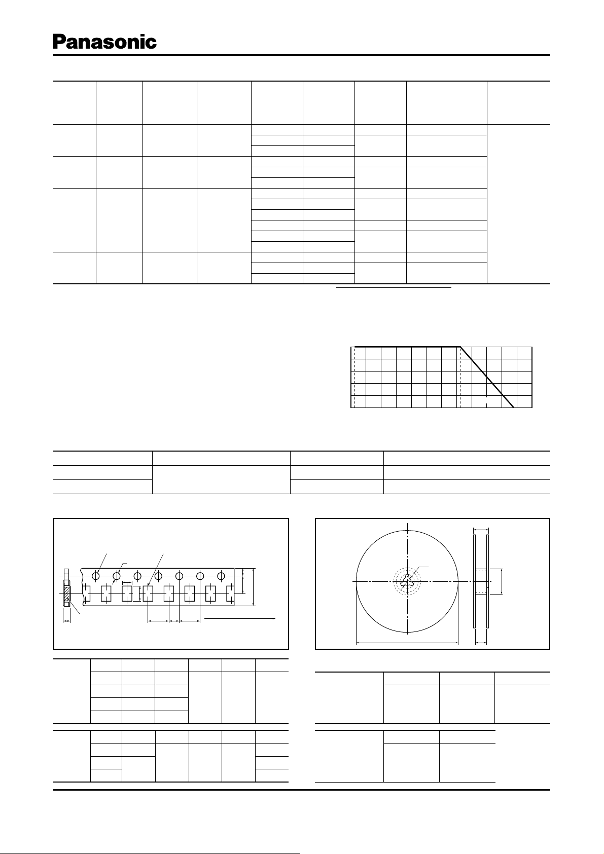
Power Derating Curve
For resistors operated in ambient temperatures above
85 °C, power rating shall be derated in ac cor dance
with the fi gure on the right.
■ Packaging Methods (Taping)
● Standard Quantity
Typ e Kin d o f Taping Pi tch (P1)Quantity
ERA2A
ERA3A, 6A, 8A
Sprocket hole Compartment
φD
A
T
Punched Carrier Taping
0
B
P1P2P
0
FE
W
Tape running directionChip component
100
Rated Load (%)
–55 °C
80
60
40
20
–40 –20 0 20 40 60 80 100 120 140 1600180–60
Ambient Temperature (°C)
85 °C
2 mm 10000 pcs./reel
4 mm 5000 pcs./reel
● Taping Reel● Carrier Taping
φC
155 °C
T
φB
φA
Typ e A B W F E
0.67
1.10
1.65
2.00
2.00
4.00
P
±0.05
±0.10
±0.15
±0.15
1
±0.10
±0.10
Dimensions
(mm)
2A
3A
6A
8A
形式
Dimensions
(mm)
2A
3A
6A, 8A
Design and specifi cations are each subject to change without notice. Ask factory for the current technical specifi cations before purchase and/or use.
Should a safety concern arise regarding this product, please be sure to contact us immediately.
1.17
1.90
2.50
3.60
2.00
±0.05
±0.10
±0.20
±0.20
P
2
±0.05
8.00
4.00
±0.20
P
0
±0.10
3.50
1.50
±0.05
D
φ
0
+0.10
–0
1.75
0.52
0.70
0.84
±0.10
T
±0.05
±0.05
±0.05
Dimensions
(mm)
Dimensions
(mm)
φ
180.0
A
+0
–3.0
B
φ
60 min. 13.0
WT
9.0
±1.0
11.4
±1.0
W
C
φ
±1.0
Feb. 2009
 Loading...