

Panasonic DVC7 User Guide
Before operating this product, please read the instructions carefully and save this
manual for future use.
Model No. AG- P
Digital Video Camera Recorder
Ò
NTSC
VQT0C34
Printed in Japan
S1202Y0
@
P
2
IMPORTANT
“Unauthorized recording of copyrighted television programs, video tapes and
other materials may infringe the right of copyright owners and be contrary to
copyright laws.”
indicates safety information.
CAUTION
RISK OF ELECTRIC SHOCK
DO NOT OPEN
CAUTION: TO REDUCE THE RISK OF ELECTRIC
SHOCK, DO NOT REMOVE COVER (OR BACK).
NO USER SERVICEABLE PARTS INSIDE.
REFER TO SERVICING TO QUALIFIED SERVICE
PERSONNEL.
The lightning flash with
arrowhead symbol, within an
equilateral triangle, is intended to
alert the user to the presence of
uninsulated “dangerous voltage”
within the product’s enclosure
that may be of sufficient
magnitude to constitute a risk of
electric shock to persons.
The exclamation point within an
equilateral triangle is intended to
alert the user to the presence of
important operating and maintenance (service) instructions in
the literature accompanying the
appliance.
CAUTION:
TO REDUCE THE RISK OF FIRE OR SHOCK
HAZARD AND ANNOYING INTERFERENCE,
USE THE RECOMMENDED ACCESSORIES
ONLY.
FCC Note:
This device complies with Part 15 of the
FCC Rules. To assure continued
compliance follow the attached installation
instructions and do not make any
unauthorized modifications.
This equipment has been tested and
found to comply with the limits for a class
A digital device, pursuant to Part 15 of the
FCC Rules. These limits are designed to
provide reasonable protection against
harmful interference when the equipment
is operated in a commercial environment.
This equipment generates, uses, and can
radiate radio frequency energy and, if not
installed and used in accordance with the
instruction manual, may cause harmful
interference to radio communications.
Operation of this equipment in a
residential area is likely to cause harmful
interference in which case the user will be
required to correct the interference at his
own expense.
CAUTION:
Do not install or place this unit in a
bookcase, built-in cabinet or any other
confined space in order to maintain
adequate ventilation. Ensure that
curtains and any other materials do not
obstruct the ventilation to prevent risk
of electric shock or fire hazard due to
overheating.
CAUTION:
Danger of explosion or fire if battery is
mistreated.
O Replace only with same or specified type.
O Do not disassemble or dispose of in fire.
O Do not store in temperatures over 60°C.
O Use specified charger for rechargeable
batteries.
O Do not recharge the battery if it is not a
rechargeable type.
For Remote Controller
O Replace battery with part No. CR2025 only.
O Do not recharge the battery.
WARNING:
TO REDUCE THE RISK OF FIRE OR
SHOCK HAZARD, DO NOT EXPOSE
THIS EQUIPMENT TO RAIN OR
MOISTURE.
TO REDUCE THE RISK OF FIRE OR
SHOCK HAZARD, KEEP THIS
EQUIPMENT AWAY FROM ALL
LIQUIDS-USE AND STORE ONLY IN
LOCATIONS WHICH ARE NOT
EXPOSED TO THE RISK OF DRIPPING
OR SPLASHING LIQUIDS, AND DO
NOT PLACE ANY LIQUID CONTAINERS
ON TOP OF THE EQUIPMENT.

3
Important Safeguards
1. Read Instructions — All the safety and
operating instructions should be read before
the unit is operated.
2. Retain Instructions — The safety and
operating instructions should be retained for
future reference.
3. Heed Warnings — All warnings on the unit
and in the operating instructions should be
adhered to.
4. Follow Instructions — All operating and
maintenance instructions should be
followed.
5. Cleaning — Unplug this video unit from the
wall outlet before cleaning. Do not use liquid
or aerosol cleaners. Use a dry cloth for
cleaning.
6. Attachments — Do not use attachments not
recommended by the video product
manufacturer as they may be hazardous.
7. Water and Moisture — Do not use this video
unit near water — for example near a bath
tub, wash bowl, kitchen sink, or laundry tub,
in a wet basement, or near a swimming pool,
and the like.
8. Accessories — Do not place this video unit
on an unstable cart, stand, tripod, bracket, or
table. The video unit may fall, causing
serious injury to a child or adult, and serious
damage to the unit. Use only with a cart,
stand, tripod, bracket, or table
recommended by the manufacturer, or sold
with the video unit. Any mounting of the unit
should follow the manufacturer’s instructions
and should use a mounting accessory
recommended by the manufacturer.
An appliance and cart
combination should be
moved with care. Quick
stops, excessive force,
and uneven surfaces
may cause the appliance
and cart combination to
overturn.
9. Ventilation — Slots and openings in the
cabinet are provided for ventilation and to
ensure reliable operation of the video unit
and to protect it from overheating. These
openings must not be blocked or covered.
Never place the video unit on a bed, sofa,
rug, or other similar surface, or near or over
a radiator or heat register. This video unit
should not be placed in a built-in installation
such as a bookcase or rack unless proper
ventilation is provided or the manufacturer's
instructions have been adhered to.
10. Power Sources — This video unit should be
operated only from the type of power source
indicated on the marking label. If you are not
sure of the type of power supply to your
home, consult your appliance dealer or local
power company. For video units intended to
be operated from battery power, or other
sources, refer to the operating instructions.
11. Grounding or Polarization — This video unit
may be equipped with either a polarized 2wire AC (Alternating Current) line plug (a
plug having one blade wider than the other)
or 3-wire grounding type plug, a plug having
a third (grounding) pin.
The 2-wire polarized plug will fit into the
power outlet only one way. This is a safety
feature. If you are unable to insert the plug
fully into the outlet, try reversing the plug. If
the plug still fails to fit, contact your
electrician to replace your obsolete outlet.
Do not defeat the safety purpose of the
polarized plug.
The 3-wire grounding type plug will fit into a
grounding type power outlet. This is a safety
feature. If you are unable to insert the plug
into the outlet, contact your electrician to
replace your obsolete outlet. Do not defeat
the safety purpose of the grounding type
plug.
12. Power-Cord Protection — Power-supply
cords should be routed so that they are not
likely to be walked on or pinched by items
placed upon or against them, paying
particular attention to cords of plugs,
convenience receptacles, and the point
where they exit from the unit.
4
Important Safeguards
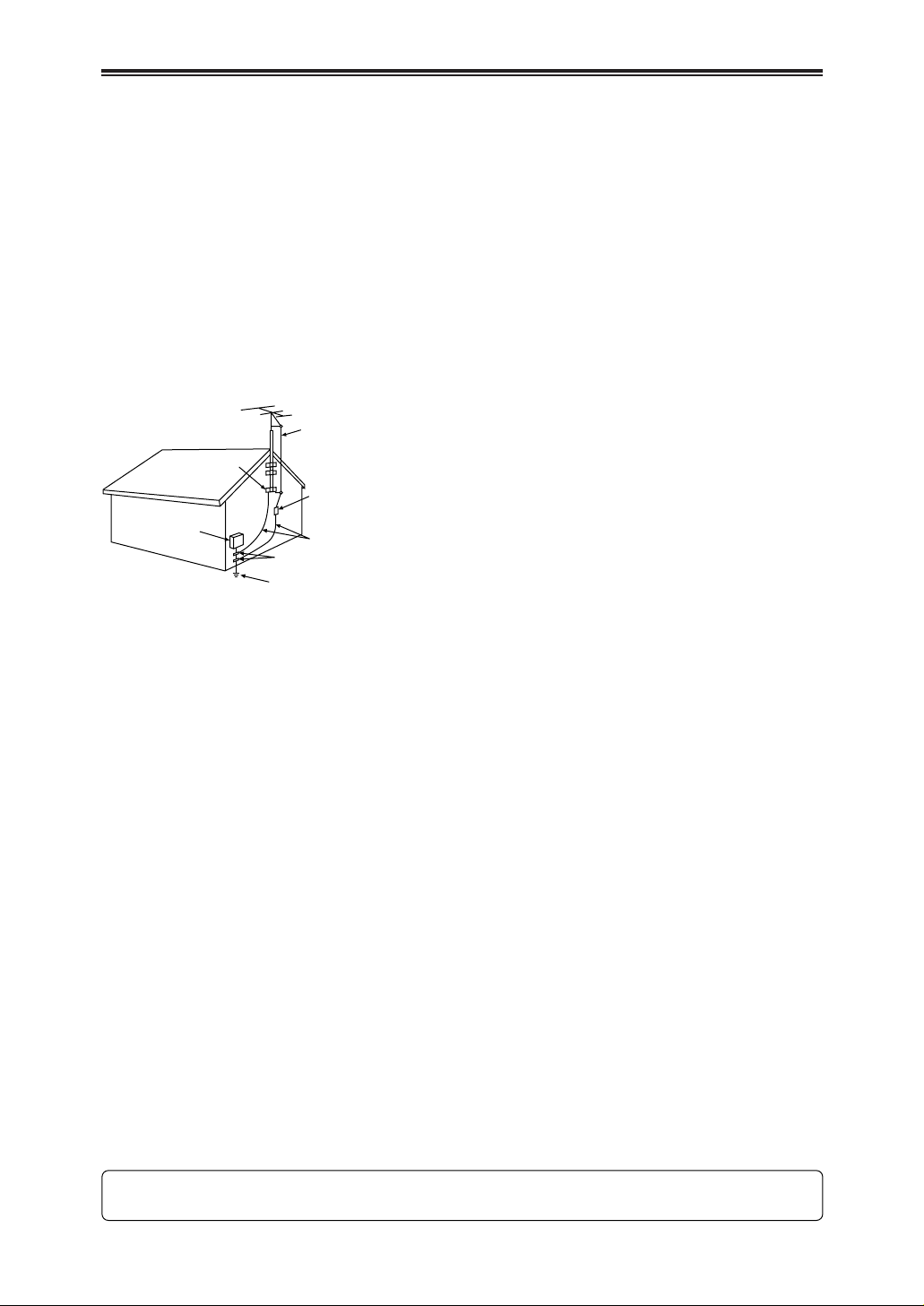
13. Outdoor Antenna Grounding — If an outside
antenna or cable system is connected to the
video unit, be sure the antenna or cable
system is grounded so as to provide some
protection against voltage surges and builtup static charges. Part 1 of the Canadian
Electrical Code, in USA Section 810 of the
National Electrical Code, provides
information with respect to proper grounding
of the mast and supporting structure,
grounding of the lead-in wire to an antenna
discharge unit, size of grounding conductors,
location of antenna discharge unit,
connection to grounding electrodes, and
requirements for the grounding electrode.
14. Lightning — For added protection of this
video unit receiver during a lightning storm,
or when it is left unattended and unused for
long periods of time, unplug it from the wall
outlet and disconnect the antenna or cable
system. This will prevent damage to the
video unit due to lightning and power-line
surges.
15. Power Lines — An outside antenna system
should not be located in the vicinity of
overhead power lines or other electric light
or power circuits, or where it can fall into
such power lines or circuits. When installing
an outside antenna system, extreme care
should be taken to keep from touching such
power lines or circuits as contact with them
might be fatal.
16. Overloading — Do not overload wall outlets
and extension cords as this can result in a
risk of fire or electric shock.
17. Objects and Liquids — Never push objects
of any kind into this video unit through
openings as they may touch dangerous
voltage points or short out parts that could
result in a fire or electric shock. Never spill
liquid of any kind onto the video unit.
18. Servicing — Do not attempt to service this
video unit yourself as opening or removing
covers may expose you to dangerous
voltage or other hazards. Refer all servicing
to qualified service personnel.
19. Damage Requiring Service — Unplug this
video unit from the wall outlet and refer
servicing to qualified service personnel
under the following conditions:
a. When the power-supply cord or plug is
damaged.
b. If any liquid has been spilled onto, or
objects have fallen into the video unit.
c. If the video unit has been exposed to rain
or water.
d. If the video unit does not operate normally
by following the operating instructions.
Adjust only those controls that are
covered by the operating instructions, as
an improper adjustment of other controls
may result in damage and will often
require extensive work by a qualified
technician to restore the video unit to its
normal peration.
e. If the video unit has been dropped or the
cabinet has been damaged.
f. When the video unit exhibits a distinct
change in performance – this indicates a
need for service.
20. Replacement Parts — When replacement
parts are required, be sure the service
technician has used replacement parts
specified by the manufacturer or have the
same characteristics as the original part.
Unauthorized substitutions may result in fire,
electric shock or other hazards.
21. Safety Check — Upon completion of any
service or repairs to this video unit, ask the
service technician to perform safety checks
to determine that the video unit is in safe
operating order.
FCC Warning: Any unauthorized changes or modifications to this equipment would void the user’s
authority to operate.
ANTENNA LEAD IN WIRE
GROUND
CLAMP
ELECTRIC
SERVICE
EQUIPMENT
NEC – NATIONAL
ELECTRICAL CODE
ANTENNA DISCHARGE UNIT
(NEC SECTION 810-20)
GROUNDING CONDUCTORS
(NEC SECTION 810-21)
GROUND CLAMPS
POWER SERVICE GROUNDING
ELECTRODE SYSTEM
(NEC ART 250, PART H)

5
Information for Your Safety
As this equipment gets hot during use,
operate it in a well-ventilated place; do not
install this equipment in a confined space
such as a bookcase or similar unit.
To reduce the risk of fire, electric shock or
product damage, do not expose this
equipment to rain, moisture, dripping or
splashing and ensure that no objects filled
with liquids, such as vases, shall be placed on
the equipment.
Camera Recorder
OThe rating plate is on the underside of the
Camera Recorder.
AC Adaptor
OThe rating plate is on the underside of the
AC Adaptor.
$ Carefully read the Operating
Instructions and use the Camera
Recorder correctly.
OInjury or material damage resulting from any
kind of use that is not in accordance with the
operating procedures explained in these
Operating Instructions are the sole
responsibility of the user.
Try out the Camera Recorder.
Be sure to try out the Camera Recorder before
recording your first important event and check that it
records properly and functions correctly.
The manufacturer is not liable for loss of recorded
contents.
The manufacturer shall in no event be liable for the
loss of recordings due to malfunction or defect of this
Camera Recorder, its accessories or cassettes.
Carefully observe copyright laws.
Recording of pre-recorded tapes or discs or other
published or broadcast material for purposes other
than your own private use may infringe copyright laws.
Even for the purpose of private use, recording of
certain material may be restricted.
OAll company and product names in the operating
instructions are trademarks or registered
trademarks of their respective corporations.
Pages for reference
Pages for reference are indicated by dashes either
side of a number, for example: -00-
$ WARNING
To prevent electric shock, do not remove the
cover (or back); there are no user serviceable
parts inside.
Refer servicing to qualified service personnel.
Use only the recommended accessories.
$ Notes about Video Head Clogging
OWhen the Camera Recorder’s video heads have
become clogged with dirt (dust and tape coating
particles), the [ ] Indication appears. In addition,
the playback picture A is distorted with mosaic-like
patterns (1 or 2 ). When the clogging further
worsens, the whole screen may be black during
playback 3 .
OTo clean video heads that have become clogged
with dirt, use the Digital Video Head Cleaner.
OIf you want to purchase the same Digital Video
Head Cleaner, please contact your Panasonic
dealer to obtain it from the Panasonic spare parts
department (part number VFK1451).
OIf the video heads again become clogged with dirt
soon after cleaning, this might be caused by
damaged tape.
In this case, stop using that cassette. We
recommend that you use Panasonic cassettes.

6
Contents
Standard Accessories . . . . . . . . . . . . . . . . . . . . . . . .7
Optional Accessories . . . . . . . . . . . . . . . . . . . . . . . . .7
Controls and Components . . . . . . . . . . . . . . . . . . . . .8
The Remote Controller . . . . . . . . . . . . . . . . . . . . . . .11
Power Supply . . . . . . . . . . . . . . . . . . . . . . . . . . . . . .12
Charging Time and Available Recording Time . . . . .13
Lens Cap and Grip Belt . . . . . . . . . . . . . . . . . . . . . .13
Attaching the Shoulder Strap . . . . . . . . . . . . . . . . . .13
Inserting a Cassette . . . . . . . . . . . . . . . . . . . . . . . . .14
Turning on the Camera Recorder and Selecting
Modes . . . . . . . . . . . . . . . . . . . . . . . . . . . . . . . . . .14
Using the Viewfinder/LCD Monitor . . . . . . . . . . . . . .15
Using the Menu Screen . . . . . . . . . . . . . . . . . . . . . .16
List of Menus . . . . . . . . . . . . . . . . . . . . . . . . . . . . . .16
Setting Date and Time . . . . . . . . . . . . . . . . . . . . . . .18
Internal Lithium Battery Recharge . . . . . . . . . . . . . .18
LP Mode . . . . . . . . . . . . . . . . . . . . . . . . . . . . . . . . . .18
Audio Recording Mode . . . . . . . . . . . . . . . . . . . . . . .18
Holding the Camera Recorder for Recording . . . . . .19
Recording . . . . . . . . . . . . . . . . . . . . . . . . . . . . . . . . .20
Photoshot . . . . . . . . . . . . . . . . . . . . . . . . . . . . . . . . .22
Zoom In/Out Functions . . . . . . . . . . . . . . . . . . . . . . .23
Digital Zoom Function . . . . . . . . . . . . . . . . . . . . . . .23
Image Stabilizer Function . . . . . . . . . . . . . . . . . . . . .24
Fade In/Out Functions . . . . . . . . . . . . . . . . . . . . . . .24
Backlight Compensation Function . . . . . . . . . . . . . .25
Wind Noise Reduction Function . . . . . . . . . . . . . . . .25
Cinema Function . . . . . . . . . . . . . . . . . . . . . . . . . . .25
Recording in Special Situations . . . . . . . . . . . . . . . .26
Recording in Natural Colors . . . . . . . . . . . . . . . . . . .26
Adjusting White Balance Manually . . . . . . . . . . . . . .27
Manual Shutter Speed Adjustment . . . . . . . . . . . . .28
Manual Iris Adjustment . . . . . . . . . . . . . . . . . . . . . . .28
Manual Focus Adjustment . . . . . . . . . . . . . . . . . . . .29
Picture Effect Functions . . . . . . . . . . . . . . . . . . . . . .29
Adjusting the Microphone Sensitivity Level . . . . . . .31
Playing Back . . . . . . . . . . . . . . . . . . . . . . . . . . . . . .32
Finding a Scene You Want to Play Back . . . . . . . . .33
Slow Motion Playback . . . . . . . . . . . . . . . . . . . . . . .33
Still Playback/Still Advance Playback . . . . . . . . . . .34
Finding the End of Recording . . . . . . . . . . . . . . . . . .34
Index Search Functions . . . . . . . . . . . . . . . . . . . . . .35
Playback Zoom Function . . . . . . . . . . . . . . . . . . . . .36
Playback Digital Effect Functions . . . . . . . . . . . . . . .36
Playing Back on Your TV . . . . . . . . . . . . . . . . . . . . .37
Audio Dubbing . . . . . . . . . . . . . . . . . . . . . . . . . . . . .38
Copying on an S-VHS (or a VHS) Cassette . . . . . . .39
Recording the Contents of Other Equipment . . . . . .39
Using the DV Cable for Recording . . . . . . . . . . . . . .40
Indications . . . . . . . . . . . . . . . . . . . . . . . . . . . . . . . .41
Warning/Alarm Indications . . . . . . . . . . . . . . . . . . . .42
Notes and Hints . . . . . . . . . . . . . . . . . . . . . . . . . . . .42
Cautions for Use . . . . . . . . . . . . . . . . . . . . . . . . . . .46
Before Requesting Repair (Problems and
Solutions) . . . . . . . . . . . . . . . . . . . . . . . . . . . . . . .50
Explanation of Terms . . . . . . . . . . . . . . . . . . . . . . . .52
Specifications . . . . . . . . . . . . . . . . . . . . . . . . . . . . . .53

7
BBBBeeeeffffoooorrrreeee UUUUssssee
ee
Standard Accessories
Illustrated are accessories supplied with the Camera
Recorder.
Optional Accessories
1) AC Adaptor (AG-B15)
2) Stereo Microphone (AG-MC15)
3) Battery Pack (Lithium/CGR-D16/
CGR-D220/1600mAh)
4) Battery Pack (Lithium/CGP-D28/
CGP-D320/2800mAh)
5) Wide Conversion Lens (AG-LW4307)
O Some optional accessories may not be available
in some countries.
1) AC Adaptor, DC Input Lead and AC Mains
Lead -12-
2) Battery Pack -12-
3) Remote Controller and Button-Type Battery
-10-, -11-
4) Lens Cap -13-
5) Shoulder Strap -13-
6) Digital Video Head Cleaner -47-
1)
2)
5)
4)
6)
3)
8
BBBBeeeeffffoooorrrreeee UUUUssssee
ee
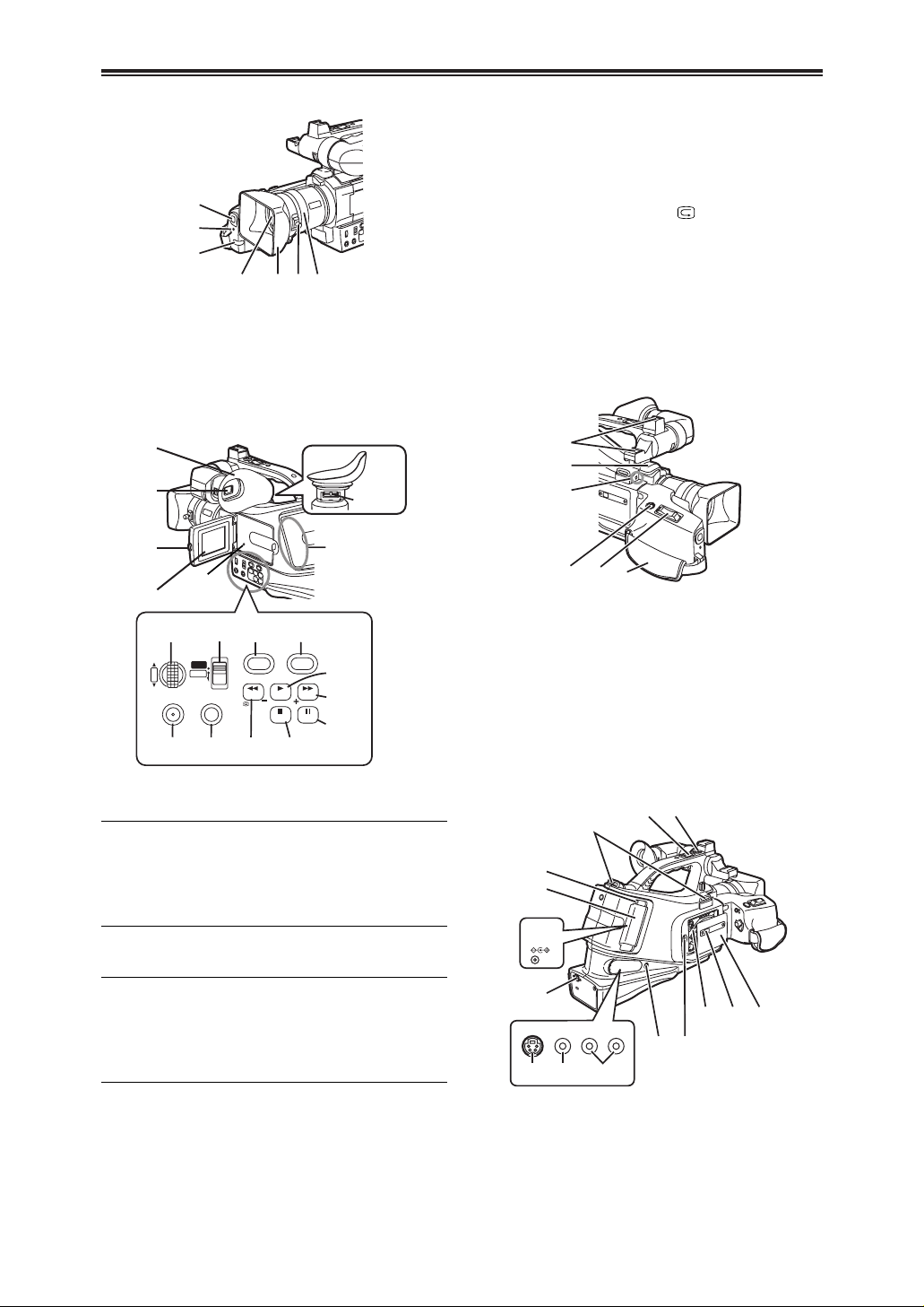
A Picture Effect Button [PIC.E.] -29-
B Menu Button [MENU] -16-
C Focus Button [FOCUS] -29-
D Rewind/Review Button [6] -32-
Reverse Search Button [SEARCH –] -20-
Recording Check Button [ ] -20-
E Stop Button [$] -32-
Fade Button [FADE] -24-
F Play Button [1] -32-
Backlight Button [BLC] -25-
G Fast Forward/Cue Button [5] -32-
Forward Search Button [SEARCH +] -20-
H Pause Button [;] -34-
Still Button [STILL] -22-
I Eyepiece Corrector Knob -15-
J Smart Accessory Shoes
OThe External Stereo Microphone (option), etc.
can be attached here.
K Microphone (built-in, stereo) -23-
L External Microphone Socket [EXT MIC]
OConnect with an external microphone or audio
equipment. (When this socket is in use, the builtin microphone does not operate.)
M Photoshot Button [PHOTO SHOT] -22-
N Zoom Lever [W/T] -23-
O Grip Belt -13-
P Shoulder Strap Holders -13-
Q Sub Zoom Lever [W/T] -19-
R Sub Recording Start/Stop Button -19-
S Battery Eject Button [PUSH] -12-
T Battery Holder
U DC Input Socket [DC IN] -12-
V DV Terminal [DV] -40-
OConnect this to the digital video equipment.
J
K
L
MNO
DC IN 7.9V
VIDEO
IN/OUT
AUDIO
L–
–R
IN/OUT
S-VIDEO
IN/OUT
Q
P
S
T
U
V
WX Y
Z[
\ ]^
R
Controls and Components
$ Camera Recorder
1 White Balance Sensor -27-
2 Recording Lamp -20-
3 Remote Control Sensor -11-
4 Lens
5 Lens Hood -49-
6 Lens Hood Attachment knob -49-
7 Focus Ring -29-
7
1
2
3
4
5
6
8 Eyecup -49-
9 Viewfinder -15-, -49-
ODue to limitations in LCD production technology,
there may be some tiny bright or dark spots on the
Viewfinder screen. However, this is not a
malfunction and does not affect the recorded
picture.
: LCD Monitor Open Button [PUSH OPEN] -15-
; LCD Monitor -15-, -49-
ODue to limitations in LCD production technology,
there may be some tiny bright or dark spots on the
LCD Monitor screen. However, this is not a
malfunction and does not affect the recorded
picture.
< Reset Button [RESET] -42-
= Speaker -32-
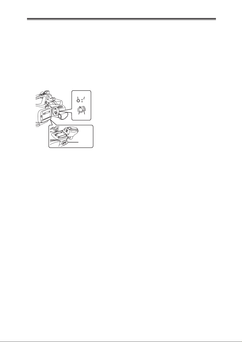
> Multi-Function Dial [PUSH] -16-, -26-, -32-
? Mode Selector Switch
[AUTO/MANUAL/PROG.AE] -20-, -26-
@ Digital Effect Button [DIG.E.] -24-
MENU FOCUS
W.B/SHUTTER/IRIS
PUSH
DIG.E. PIC.E.
BLC
FADE STILL
SEARCHSEARCH
MANUAL
PROG. AE
AUTO
VOL/JOG
8
9
:
;
<
=
>
BCD E
F
G
H
?@ A
I
9
BBBBeeeeffffoooorrrreeee UUUUssssee
ee
Controls and Components
$ Camera Recorder
W S-Video Input/Output Socket [S-VIDEO IN/OUT]
-37-, -39-
X Video Input/Output Socket [VIDEO IN/OUT]
-37-, -39-
Y Audio Input/Output Sockets [AUDIO IN/OUT]
-37-, -39-
Z Headphone Socket [PHONES] -44-
[ Cassette Eject Lever [<EJECT] -14-
\ Cassette Holder
] Cassette Compartment Lock Button
[PUSH LOCK] -14-
^ Cassette Compartment Cover -14-
_ Mode Button [MODE] -32-
` Operation Mode Lamps [CAMERA/VCR]
-14-, -20-, -32-
a Recording Start/Stop Button -20-
b Off/On Switch [OFF/ON] -14-, -20-, -46-
c Tripod Receptacle
OUsed for mounting the Camera Recorder on a
tripod.
CAMERA
VCR
MODE
OFF ON
_`
ab
c
10
BBBBeeeeffffoooorrrreeee UUUUssssee
ee
Controls and Components
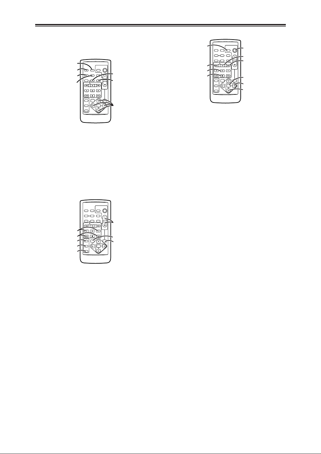
$ Remote Controller
Using the wireless Remote Controller that is supplied
with the Camera Recorder, most of the Camera
Recorder functions can be operated from a distance.
d Date/Time Button [DATE/TIME] -41-
e Indication Output Button [OSD] -37-
f Counter Indication Shift Button [COUNTER]
-41-
g Reset Button [RESET] -52-
h Recording Button [REC] -39-, -40-
i Audio Dubbing Button [A.DUB] -38-
j Cursor Buttons for Variable Speed Search
Function [V,B] -33-
Direction Buttons for Playback Zoom Function
[V,B, N, M] -36-
k Slow Motion/Still Advance Buttons [E, D]
(E: reverse, D:forward) -33-
l Index Search Buttons [:,9]
(:: reverse, 9:forward) -35-
m Selection Button [SELECT] -36-
n Store Button [STORE] -36-
o Off/On Button [OFF/ON] -36-
p Zoom/Volume Button [ZOOM/VOL]
-23-, -32-, -36-
q Variable Speed Search Button [VAR. SEARCH]
-33-
r Playback Zoom Button [P.B. ZOOM] -36-
The following buttons function in the same manner as
the corresponding buttons on the Camera Recorder.
s Photoshot Button [PHOTO SHOT] -22-
t Rewind/Review Button [6] -20-, -33-
u Pause Button [;] -34-
v Stop Button [$] -32-
w Recording Start/Stop Button [START/STOP]
-20-
x Play Button [1] -32-
y Fast-forward/Cue Button [5] -32-
z Menu Button [MENU] -16-
{ Set Button [SET] -16-
| Item Button [ITEM] -16-
OSD
COUNTER
RESET TITLE
STILL ADV
PAUSE
STILL ADV
INDEX
SELECT
STORE
OFF/ON
P.B.DIGITAL
VAR.
SEARCH
– VOL +
PB.
ZOOM
MENU
SET
ITEM
STOP INDEX
MULTI/
P-IN-P
REC A.DUB
PLAY
C
/REW FF/
B
ZOOM
DATE/
TIME
PHOTO
SHOT
START/
STOP
d
e
f
g
h
i
j
OSD
COUNTER
RESET TITLE
STILL ADV
PAUSE
STILL ADV
INDEX
SELECT
STORE
OFF/ON
P.B.DIGITAL
VAR.
SEARCH
– VOL +
PB.
ZOOM
MENU
SET
ITEM
STOP INDEX
MULTI/
P-IN-P
REC A.DUB
PLAY
C
/REW FF/
B
ZOOM
DATE/
TIME
PHOTO
SHOT
START/
STOP
k
p
q
r
l
m
n
o
OSD
COUNTER
RESET TITLE
STILL ADV
PAUSE
STILL ADV
INDEX
SELECT
STORE
OFF/ON
P.B.DIGITAL
VAR.
SEARCH
– VOL +
PB.
ZOOM
MENU
SET
ITEM
STOP INDEX
MULTI/
P-IN-P
REC A.DUB
PLAY
C
/REW FF/
B
ZOOM
DATE/
TIME
PHOTO
SHOT
START/
STOP
s
t
u
v
w
x
y
z
{
|
11
BBBBeeeeffffoooorrrreeee UUUUssssee
ee
The Remote Controller
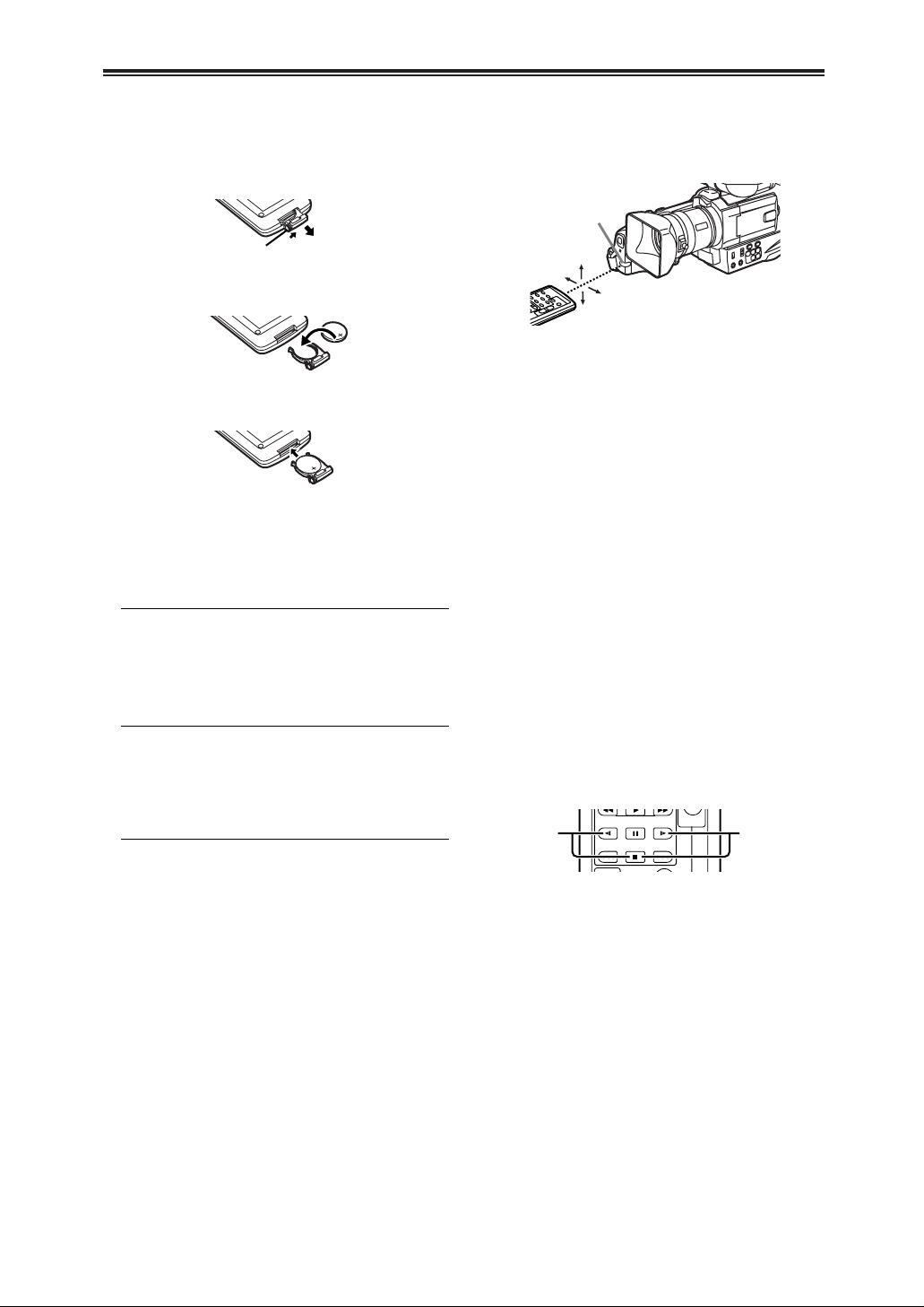
$ Inserting a Button-type Battery
Before using the Remote Controller, insert the
supplied button-type battery.
1
1
While pressing the Stopper 1, pull out the
Battery Holder.
$ Using the Remote Controller
3
1
Direct the Remote Controller to the Remote
Control Sensor 3 of the Camera Recorder and
press an appropriate button.
ODistance from the Camera Recorder:
Within approximately 5 metres
OAngle:
Within approximately 15° in the vertical and
horizontal directions from the central axis
OThe above operative ranges are for indoor use.
Outdoors or under strong light, the Camera
Recorder may not operate properly even within the
above ranges.
OWithin a 1-metre range, you can also use the
Remote Controller on the LCD Monitor side of the
Camera Recorder.
Selecting Remote Controller Modes
When 2 Movie Cameras are used simultaneously,
they can be operated individually by selecting different
Remote Controller Modes.
OIf the Remote Controller Mode of the Camera
Recorder and that of the Remote Controller do not
match, [REMOTE] Indication is displayed.
Setup on the Camera Recorder:
Set [REMOTE] on the [OTHER FUNCTIONS] SubMenu to the desired Remote Controller Mode. (-16-)
Setup on the Remote Controller:
[VCR1]:
Press the [D] Button and [$] Button
simultaneously. 1
[VCR2]:
Press the [E] Button and [$] Button
simultaneously. 2
OWhen the battery in the Remote Controller is
replaced, the mode is automatically reset to [VCR1]
Mode.
2
Insert the button-type battery with the (+)
marking facing upward.
3
Insert the Battery Holder into the Remote
Controller.
OWhen the button-type battery is exhausted,
replace it with a new CR2025 battery. (A battery
is normally expected to last about 1 year.
However, it depends on operation frequency.)
OMake sure to match the poles correctly when
inserting the battery.
CAUTION
Danger of explosion if battery is incorrectly
replaced. Replace only with the same or equivalent
type recommended by the equipment
manufacturer. Discard used batteries according to
manufacturer’s instructions.
WARNING
Risk of fire, explosion and burns. Do not recharge,
disassemble, heat above 60°C or incinerate. Keep
the Button-Type battery out of the reach of children.
Never put Button-Type battery in mouth. If
swallowed call your doctor.
15˚
15˚
15˚
15˚
STILL ADV
PAUSE
INDEX
STILL ADV
STOP INDEX
21
12
BBBBeeeeffffoooorrrreeee UUUUssssee
ee
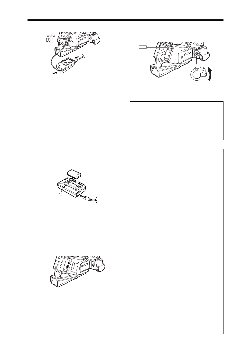
Power Supply
$ Using the AC Adaptor
DC IN 7.9V
U
1
Connect the AC Mains Lead to the AC Adaptor
and the AC mains socket.
2
Connect the DC Input Lead to the [DC IN]
Socket U on the Camera Recorder.
3
Connect the DC Input Lead to the AC Adaptor.
OBefore connecting or disconnecting the power
supply, set the [OFF/ON] Switch on the Camera
Recorder to [OFF] and make sure that
[CAMERA/VCR] Lamps is not lit.
$ Using the Battery
Before use, fully charge the Battery.
OFor other notes concerning this item, see -42-.
1
Attach the Battery to the AC Adaptor and
charge it.
OSince the Battery will not be charged when the
DC Input Lead is connected to the AC Adaptor,
disconnect it from the AC Adaptor.
OThe [CHARGE] Lamp lights up, and charging
starts.
OWhen the [CHARGE] Lamp goes off, charging is
completed.
2
Attach the charged Battery to the Camera
Recorder.
PUSH
OFF ON
S
b
Disconnecting the Power Source
Set the [OFF/ON] Switch b to [OFF] and, disconnect
the DC Input Lead or remove the Battery.
OWhile pressing the [PUSH] Button S with your
index, remove the battery by pushing it up with your
thumb.
O Do not bring metal objects (such as
necklaces or hairpins) into contact with the
battery terminals. The terminals may short
circuit and generate heat, and touching them
in this condition may cause severe burns.
O The battery heats up during operation and during
charging, as does the camera recorder body.
O If recording and stop operations are repeated
more than is necessary, the recording time will
be less than the values given in the above table.
O Store the battery only when it is fully discharged.
It is recommended that the battery be charged
once a year when it is being stored long-term
and that it be placed back in storage after it has
been fully discharged using the camera recorder.
O When the temperature of the battery unit has
risen to an extremely high level or dropped to an
extremely low level or when the battery is not
used for prolonged periods of time has become
fully discharged, the “CHARGE” lamp flashes
several times, and charging commences
automatically.
O If the “CHARGE” lamp continues to flash even
though the battery temperature is normal, consult
your dealer as a problem may have developed
within the battery or AC adapter.
O When the battery is warm, it takes longer than
usual for the battery to be charged.
O When the AC adapter is used near a radio, the
radio sound may be distorted. Use the adapter
at a distance of at least one meter from the radio.
O Noise may be heard while the AC adapter is in
use; however, this is normal and not indicative of
any malfunctioning.
O The battery cannot be charged while supplying
power from the AC adapter to the camera
recorder.
CAUTION:
This unit will operate on 110/120/220/240V AC.
An AC plug adapter may be required for voltages
other than 120V/AC.
If a conversion plug is required, consult with your
dealer as to which one is to be purchased.
13
BBBBeeeeffffoooorrrreeee UUUUssssee
ee
Charging Time and Available Recording Time
Battery supplied
ACharging Time
BMaximum Continuous Recording Time
CIntermittent Recording Time
(Intermittent Recording Time is the available recording
time with repeated recording and stopping actions.)
“1h10min.” indicates 1 hour and 10 minutes.
OThe times shown in the table are approximate
times. The numbers in parentheses indicate the
recording time when the LCD Monitor is used. In
actual use, the available recording time may be
shorter.
OThe times shown in the table are for continuous
recording at a temperature of 20°C and humidity of
60%. If the Battery is charged at a higher or lower
temperature, the charging time may be longer.
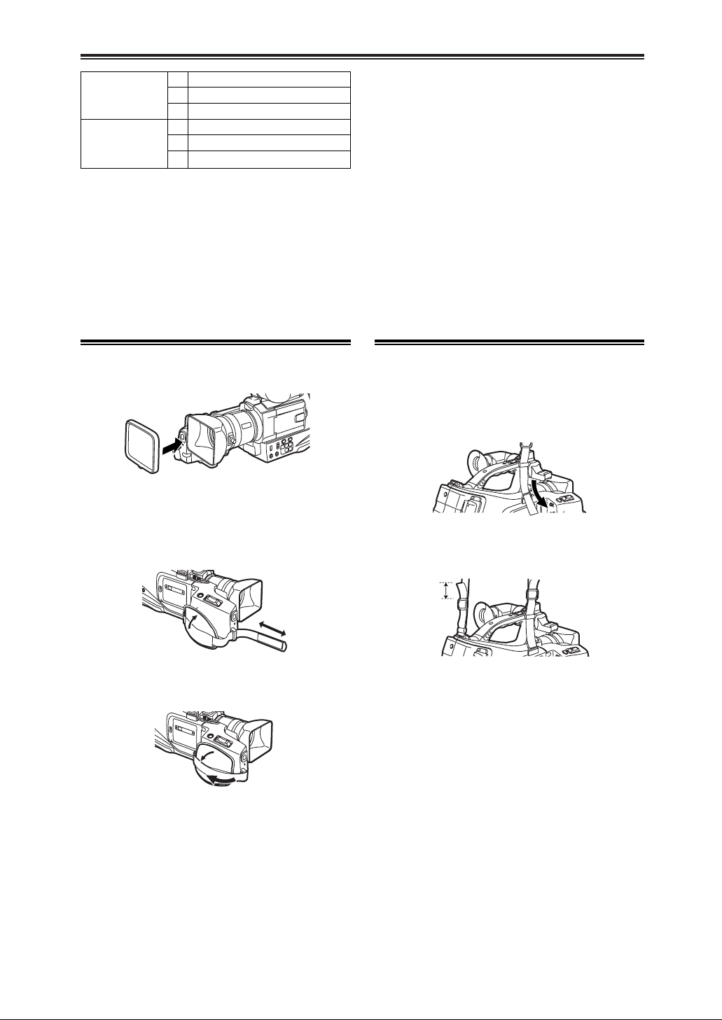
Lens Cap and Grip Belt
$ Attach the Lens Cap
To protect the Lens surface, attach the Lens Cap.
$ Adjust the Grip Belt
Adjust the length of the Grip Belt to the size of your
hand.
1
Detach the tip of the Grip Belt.
1
Pull the end of the Shoulder Strap through the
Shoulder Strap Holder on the Camera Recorder.
2
Adjust the length.
3
Reattach the Grip Belt.
2h.
A
3h30min. (2h55min.)
B
1h45min. (1h30min.)
C
CGP-D28
3h15min.
A
6h5min. (5h)
B
3h (2h30min.)
C
Attaching the Shoulder Strap
We recommend that you attach the Shoulder Strap
before going out of doors to record so as to avoid
dropping the Camera Recorder.
2
Fold the tip of the Shoulder Strap, run it
through the Shoulder Strap Length Adjuster,
and pull it.
OPull it out more than 1.5 inch 1 from the
Shoulder Strap Length Adjuster so that it cannot
slip off.
1
14
BBBBeeeeffffoooorrrreeee UUUUssssee
ee
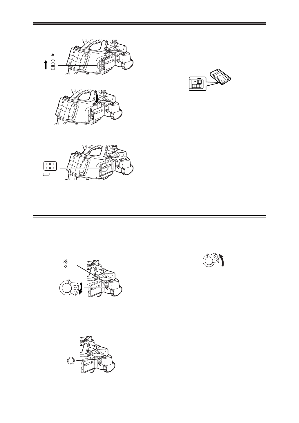
Inserting a Cassette
1
Slide the [<EJECT] Lever [ to open the Cover.
EJECT
3
[
2
Insert a Cassette.
3
Close the Cover and press the [PUSH LOCK]
Button ] to lock the cover.
PUSH
LOCK
]
$ Accidental Erasure Prevention
Opening the accidental erasure prevention slider 1
on the cassette (by sliding it in the [SAVE] arrow
direction) prevents the tape from recording. To enable
recording, close the accidental erasure prevention
slider (by sliding it in the [REC] arrow direction).
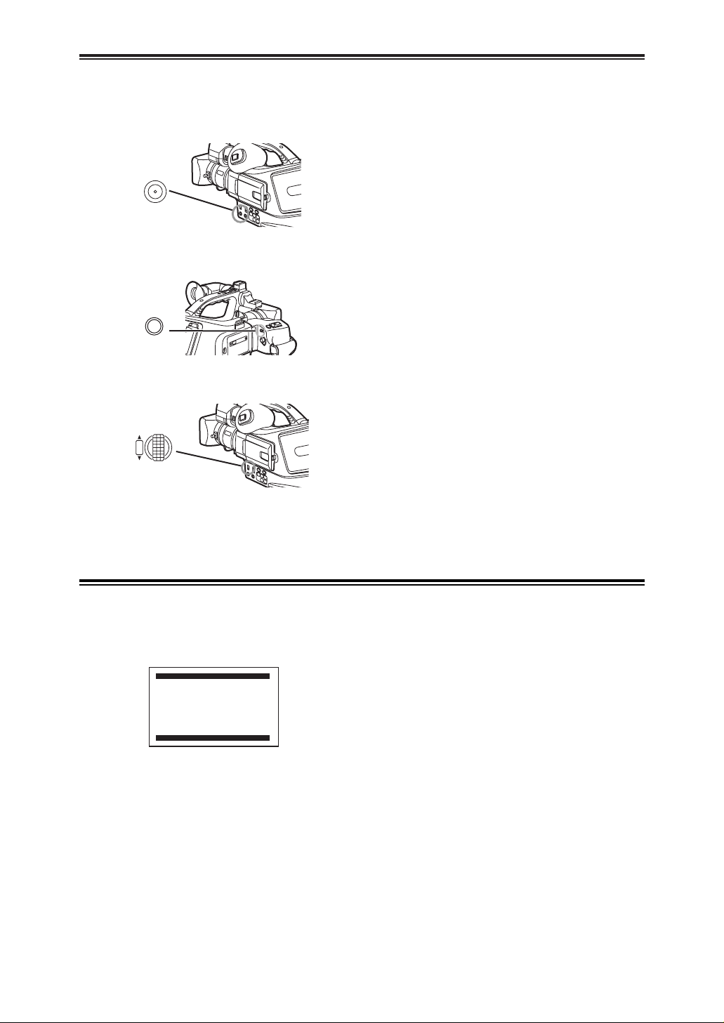
Turning on the Camera Recorder and Selecting Modes
1
Set the [OFF/ON] Switch b to [ON].
OThe [CAMERA] Lamp ` lights up.
OFF ON
CAMERA
VCR
`
b
2
Press the [MODE] Button _.
OWith each press, the Mode changes.
OThe appropriate Mode Lamp lights up.
MODE
_
Turn on the power first and then select modes.
$ How to Turn on the Power
$ How to Switch Modes
3
Set the [OFF/ON] Switch b to [OFF].
OFF ON
b
$ How to Turn off the Power
OFor other notes concerning this item, see -42-.
R E C
SAVE
1
15
BBBBeeeeffffoooorrrreeee UUUUssssee
ee
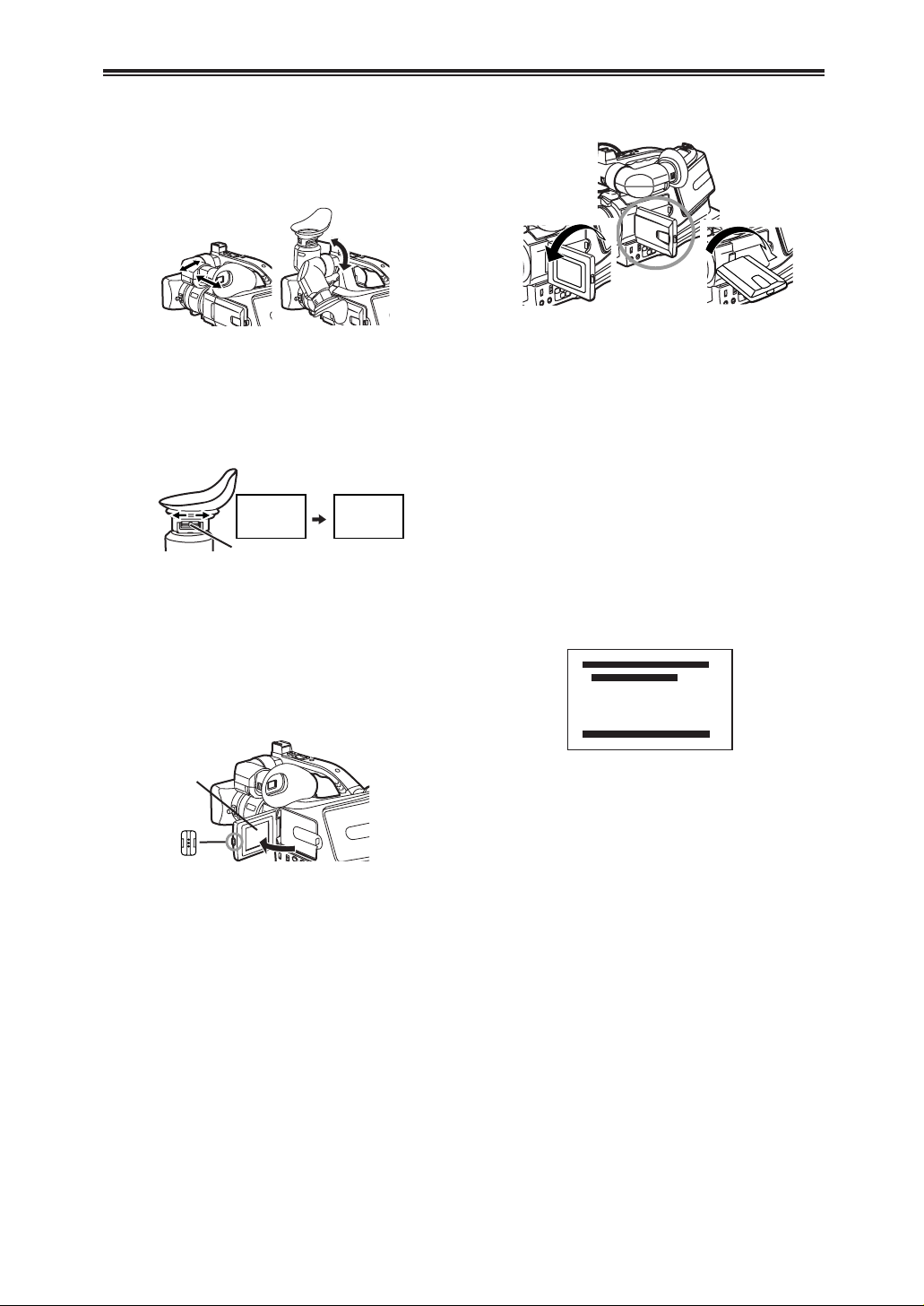
Using the Viewfinder/LCD Monitor
1
Pull out the Viewfinder and tilt it up.
OThe angular part of the Viewfinder can be turned
upward by 80° and downward by 38°.
ODo not pull on the Eyecup to extend the
Viewfinder.
2
Adjust by sliding the Eyepiece Corrector Knob
I.
12:30:45 AM
OCT 15 2002
12:30:45 AM
OCT 15 2002
12:30:45 AM
OCT 15 2002
12:30:45 AM
OCT 15 2002
I
$ Using the Viewfinder
Before using the Viewfinder, adjust the field of view so
that the displays inside the Viewfinder become clear
and easy to read.
1
Press the [PUSH OPEN] Button : and, at the
same time, bring the LCD Monitor ; out about
90° in the direction of the arrow.
OThe Viewfinder goes off.
:
;
2
Adjust the LCD Monitor angle according to the
desired recording angle.
OThe LCD Monitor can rotate a maximum of 180°
1 from the vertical position to the upward
direction and a maximum of 90° 2 to the
downward direction. Forcefully rotating the LCD
Monitor beyond these ranges will damage the
Camera Recorder.
OWhen you open the LCD Monitor, be sure that
the LCD Monitor and the Viewfinder cannot
touch.
Closing the LCD Monitor
Push the LCD Monitor until it is securely locked.
180°
1
90°
2
$ Using the LCD Monitor
With the LCD Monitor open, you can also record the
picture while watching it.
$ Adjusting Brightness and Color Level
When [LCD/EVF SET] on the [DISPLAY SETUP] SubMenu is set to [YES], the following items are
displayed.
LCD Brightness [LCD BRIGHTNESS]
It adjusts the brightness of the image on the LCD
screen.
LCD Color Level [LCD COLOR LEVEL]
It adjusts the color saturation of the image on the
LCD screen.
Brightness of the Viewfinder [EVF BRIGHTNESS]
It adjusts the brightness of the image in the
Viewfinder.
To Adjust
Press the [PUSH] Dial and select the item to be
adjusted, and then turn the [PUSH] Dial to raise or
lower the number of vertical bars in the Bar Indication.
OA larger number of vertical bars indicates stronger
brightness or color saturation.
Increasing the Brightness of the Entire LCD
Monitor
Set the [LCD MODE] on the [DISPLAY SETUP] SubMenu to [BRIGHT].
OThese adjustments do not affect the recorded
images.
OFor other notes concerning this item, see -49-.
LCD/EVF SET
PUSH MENU TO RETURN
LCD BRIGHTNESS
[-]||||----[+]
LCD COLOR LEVEL
[-]||||----[+]
EVF BRIGHTNESS
[-]||||----[+]
16
BBBBeeeeffffoooorrrreeee UUUUssssee
ee
Using the Menu Screen
1
Press the [MENU] Button B.
OThe Menu corresponding to the Mode selected
by using the [MODE] Button _ is displayed.
MENU
B
2
Turn the [PUSH] Dial > to select a desired SubMenu.
3
Press the [PUSH] Dial > to display the selected
Sub-Menu.
4
Turn the [PUSH] Dial > to select the item to be
set.
5
Press the [PUSH] Dial > to set the selected
item to a desired mode.
OWith each press of the [PUSH] Dial, the cursor
[1] moves to the next mode. Menu items that
cannot be used in combination with the selected
item are displayed in dark blue.
OTurn the [PUSH] Dial > to display the
highlightened item.
W.B/SHUTTER/IRIS
PUSH
VOL/JOG
>
MODE
_
To facilitate the selection of a desired function or
setup, this Camera Recorder displays various function
setups on Menus.
OWhile a Menu is displayed, you cannot record or
play back. Menus can be displayed during playback
but not during recording. The above operations can
be done using the [MENU] Button, [SET] Button
and [ITEM] Button on the Remote Controller. (-11-)
To Exit the Menu Screen
Press the [MENU] Button again.
About the Menu Mode Setting
The setting selected on the Menu will be retained
even when the Camera Recorder is turned off.
However, if the Battery or AC Adaptor is disconnected
before turning off the Camera Recorder, the selected
setup may not be retained. (But, the setups of
[NEGA], [SEPIA], [MONO] or [SOLARI] (-29-) are not
retained.)
OMenu operation flow is shown in this text by >>.
[1. CAMERA SETUP]
Camera Setup Sub-Menu
[PROGRESSIVE]
Progressive Photoshot Mode -22-
[D.ZOOM]
Digital Zoom -23-
[CINEMA]
Cinema-like Format Recording -25-
[P.EFFECT]
Picture Effects -29-
[RETURN]
Returning to the Main-Menu
OIf you set [RETURN] to [YES], the menu changes
back to the Main-Menu.
[2. RECORDING SETUP]
Recording Setup Sub-Menu
[REC SPEED]
Recording Speed Mode -18-
[AUDIO REC]
Audio Recording Mode -18-
[SCENEINDEX]
Scene Index Mode -35-
[WIND CUT]
Wind Noise Reduction -25-
[ZOOM MIC]
Zoom Microphone -23-
[MIC LEVEL ADJ.]
Microphones Sensitivity Level -31-
[RETURN]
Returning to the Main-Menu
List of Menus
The figures of the Menus are for explanation purposes
only, and they are different from the actual Menus.
$ [CAMERA FUNCTIONS]
Camera Mode Main-Menu
CAMERA FUNCTIONS
PUSH MENU TO EXIT
1.CAMERA SETUP
2.RECORDING SETUP
3.DISPLAY SETUP
4.OTHER FUNCTIONS

17
BBBBeeeeffffoooorrrreeee UUUUssssee
ee
List of Menus
[1. PLAYBACK FUNCTIONS]
Playback Functions Sub-Menu
[BLANK SEARCH]
Blank Search -34-
[SEARCH]
Index Search Mode -35-
[12bit AUDIO]
Audio Selector -38-
[AUDIO OUT]
Audio Output Mode -44-
[RETURN]
Returning to the Main-Menu
[2. DIGITAL EFFECT]
Playback Digital Effect Functions Sub-Menu
[EFFECT]
Digital Effect On/Off -36-
[EFFECT SELECT]
Digital Effect Selection -36-
[RETURN]
Returning to the Main-Menu
[3. RECORDING SETUP]
Recording Setup Sub-Menu
[REC SPEED]
Recording Speed Mode -18-
[AUDIO REC]
Audio Recording Mode -18-
[AUDIO LEVEL]
Audio Level Setting -38-
[RETURN]
Returning to the Main-Menu
[4. AV IN/OUT SETUP]
Audio-Video Input/Output Setup Sub-Menu
[AV JACK]
AV Socket -38-
[A.DUB INPUT]
Audio Dubbing Input -38-
[DV OUT]
Analog-Digital Conversion Output -45-
[RETURN]
Returning to the Main-Menu
[5. DISPLAY SETUP]
Display Setup Sub-Menu
OAll of the items on the [DISPLAY SETUP] Sub-
Menu are the same as those on the [DISPLAY
SETUP] Sub-Menu of the [CAMERA FUNCTIONS]
Main-Menu.
[6. OTHER FUNCTIONS]
Other Functions Sub-Menu
[REMOTE]
Remote Controller Mode -11-
[CLOCK SET]
Date and Time Setting -18-
[RETURN]
Returning to the Main-Menu
$ [VCR FUNCTIONS]
VCR Mode Main-Menu
PUSH MENU TO EXIT
2.DIGITAL EFFECT
3.RECORDING SETUP
4.AV IN/OUT SETUP
5.DISPLAY SETUP
6.OTHER FUNCTIONS
1.PLAYBACK FUNCTIONS
VCR FUNCTIONS
[3. DISPLAY SETUP]
Display Setup Sub-Menu
[DATE/TIME]
Date and Time Indication -41-
[C.DISPLAY]
Counter Display Mode -41-
[C.RESET]
Counter Reset -52-
OIt resets the counter to zero. However, it cannot
reset the Time Code.
[DISPLAY]
Display Mode -41-
[LCD MODE]
LCD Lighting Mode -15-
[LCD/EVF SET]
LCD and Viewfinder Adjustment -15-
[RETURN]
Returning to the Main-Menu
[4. OTHER FUNCTIONS]
Other Functions Sub-Menu
[REMOTE]
Remote Controller Mode -11-
[REC LAMP]
Recording Lamp -20-
[BEEP SOUND]
Beep Sound -42-
[SHTR EFFECT]
Shutter Effect -22-
[CLOCK SET]
Date and Time Setting -18-
[SELF REC]
Recording Yourself -21-
[RETURN]
Returning to the Main-Menu
 Loading...