

Page 1
Digital Copier
Setup Procedure
Model No.
DP-130/135/150 Series
Option
Model No.
DA-DS150
Table of Contents
Setup Procedure ............................. 2
Before setting up
Releasing Scanner
Removing Shipping Materials
Installing Toner Cartridge
Installing Paper
Connecting Printer Cable and
Telephone Line
Setup Procedure For Option.......... 8
2nd Paper Feed Module
Handset Unit
Expansion Flash Memory Card
Installing Printer Driver ................ 12
For Windows 95/98
For Windows NT 4.0
For Windows 2000
Installing Panasonic
Document Management System .. 24
Installing Panasonic Class 2 Fax
Modem........................................... 27
For Windows 95/98
For Windows NT 4.0
For Windows 2000
DA-DS150
This setup guide includes the setup procedure
not only for the main unit but also for options.
Please keep this guide.
You will need it when you buy the options.
Page 2
Setup Procedure
Before setting up
■■
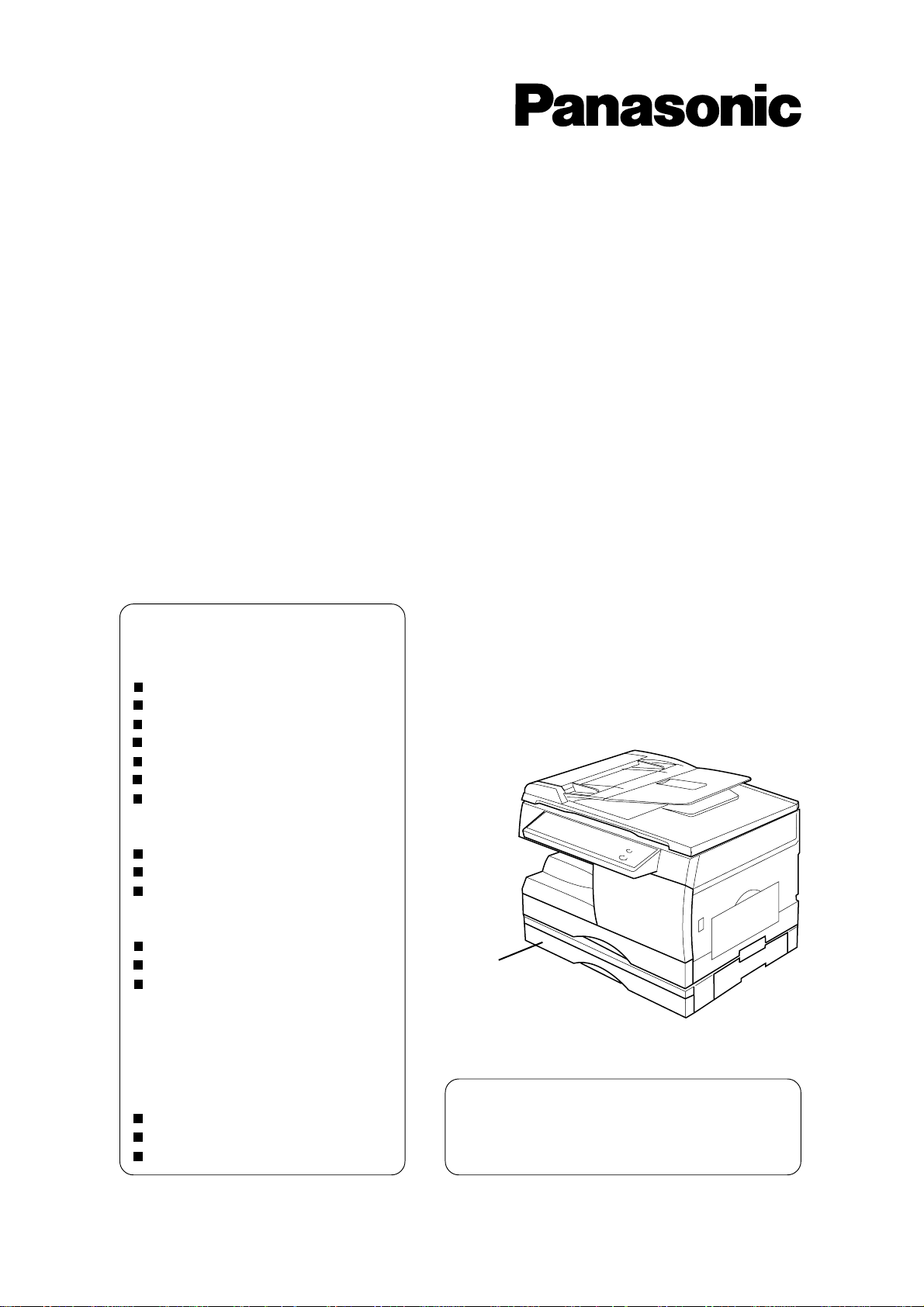
■ Unpack and install on a stable flat surface.
■■
Check that you have all the contents illustrated.
Note: Do not plug the copier until directed to do so.
Copier
Toner Cartridge
(1 piece)
■■
■ Minimum Space Requirement
■■
Operating Instructions
C
For Copier (1 piece)
C
For Facsimile (1 piece)
C
CD-ROM (1 piece)
C
Setup Guide (1 piece)
Cable
C
Pac k ed in the paper tr a y
ATTENTION
100 mm
300 mm
Copier Sheet BypassExit Tray
C
Use only the setup units/parts designated by Panasonic. If the copier should
be damaged by using other setup units/parts, Panasonic will not bear any
responsibility.
C
Drum unit already comes installed in copier.
700 mm
2
Page 3

Setup Procedure
Set up the main unit
1
■■
■ Following procedure needs to power on.
■■
2
3
Do not plug the main unit for these
operations.
Releasing the scanner
Installing the toner cartridge
Removing shipping materials
Installing paper
(See P.##)
Printer
# Install the printer driver software
from the CD-ROM. (See P.##)
$ Connect the pr inter to the PC
with a bi-directional parallel
interface cable (36 pins)
Fax
# Connect the telephone line and
the handset cable. (See P.##)
$ Set up the dialing method (See
P.##)
4
ATTENTION
Extended Functions
Install the extended function y ou need by
following the instructions of the CD-ROM
C
Scanner
C
Device Setting
C
Phone Book
C
Status Monitor
C
Panasonic Document Management
System
C
Use only the setup units/parts designated by Panasonic. If the copier should be
damaged by using other setup units/parts, Panasonic will not bear any
responsibility.
C
Unplug the power code when setting up the main unit.
3
Page 4
Setup Procedure
Release Scanner/Remove shipping materials
■■
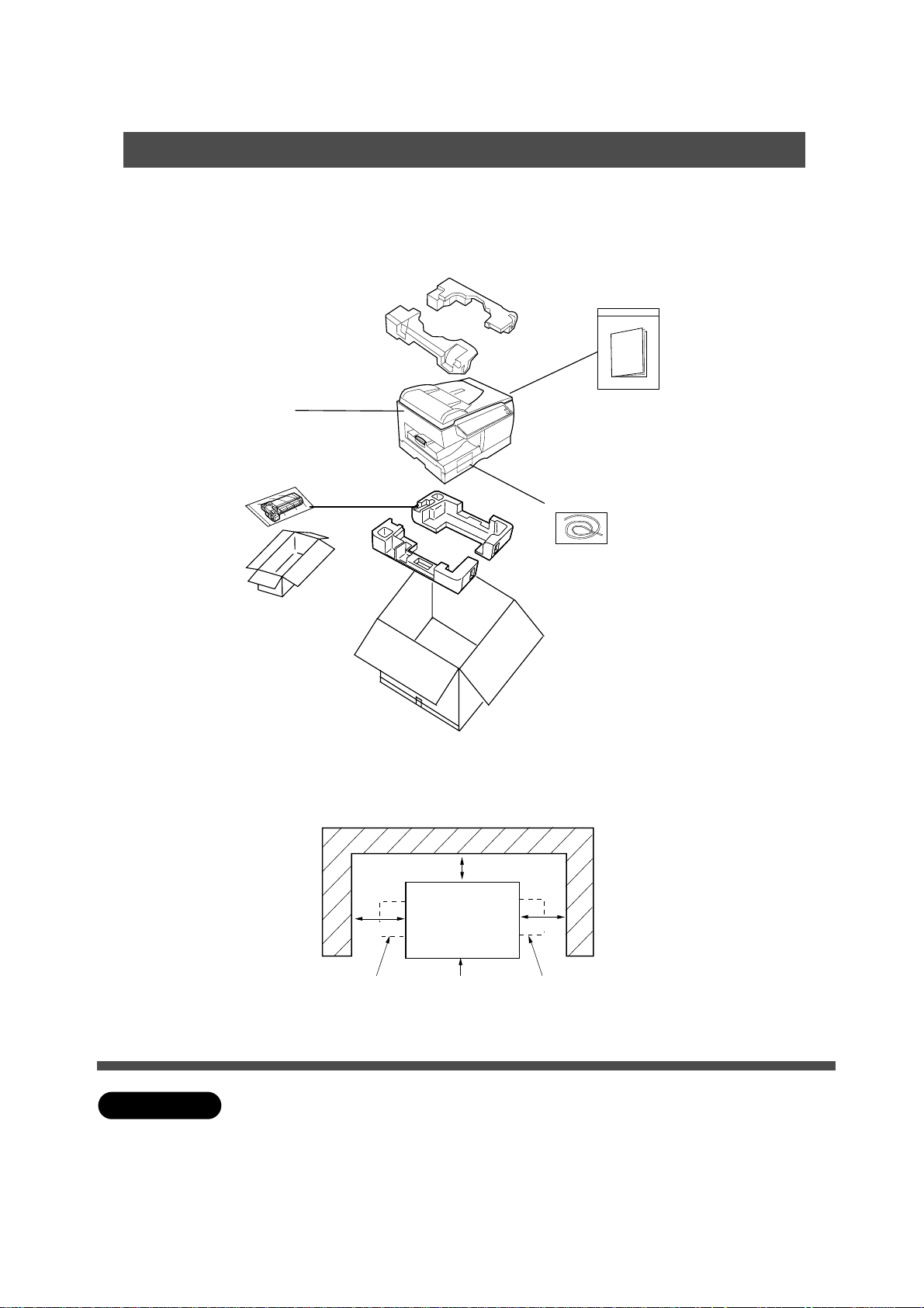
■ Do not plug the copier until directed to do so.
■■
Remove the fixing screw for the
optics unit.
1
Pull paper tray out of copier and
secure the screw to the bottom of
2
the paper tray.
Note: When moving the copier reinstall
the fixing screw.
3
4
5
Bottom view
# Completely remove the paper
tray from the copier.
$ Release the shipping tapes
(2 pieces) from the bottom.
% Push the bottom plate lock
button.
Remove the shipping tapes from
the bottom plate. (2 pieces)
# Remove the shipping tape.
$ Open the sheet bypass.
% Push the button.
& Open the r ight cover.
ATTENTION
C
Do not plug in copier until set-up is complete.
4
Page 5
Setup Procedure
Remove shipping materials/Install Toner Cartridge
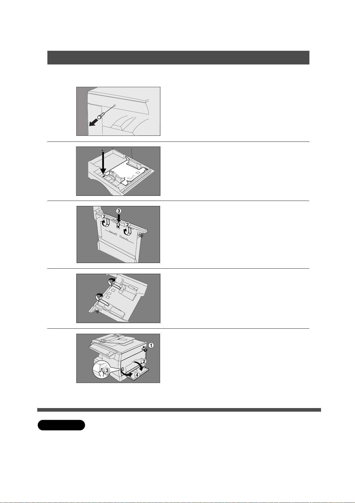
Remove the shipping material of
fuser unit.
6
7
8
# Remove the tapes.
(2 pieces)
$
Pull out the shipping materials (white string
with 2 blue stoppers) from the fuser unit.
Open the front panel.
C
Do not open the front panel first. It can
not be opened unless you open the
covers shown in procedure 5.
# Shake the toner cartridge
several times.
$ Take off the toner cartridge
cover (white plastic) and
discard.
Do not touch the magnetic roller!
Do not stand the toner cartridge on end!
9
10
ATTENTION
Install the toner cartr idge.
# Push the toner cartridge until it
stops.
$
Handle
C
For optimum cop y quality use the recommended P anasonic toner cartridge.
Store toner cartridge in a cool dark place. Install toner cartridge immediately
after unsealing.
Push the green handle until it locks .
% Close the front panel.
&
Close the right cover. (See page 7)
( Close the sheet bypass.
5
Page 6
Setup Procedure
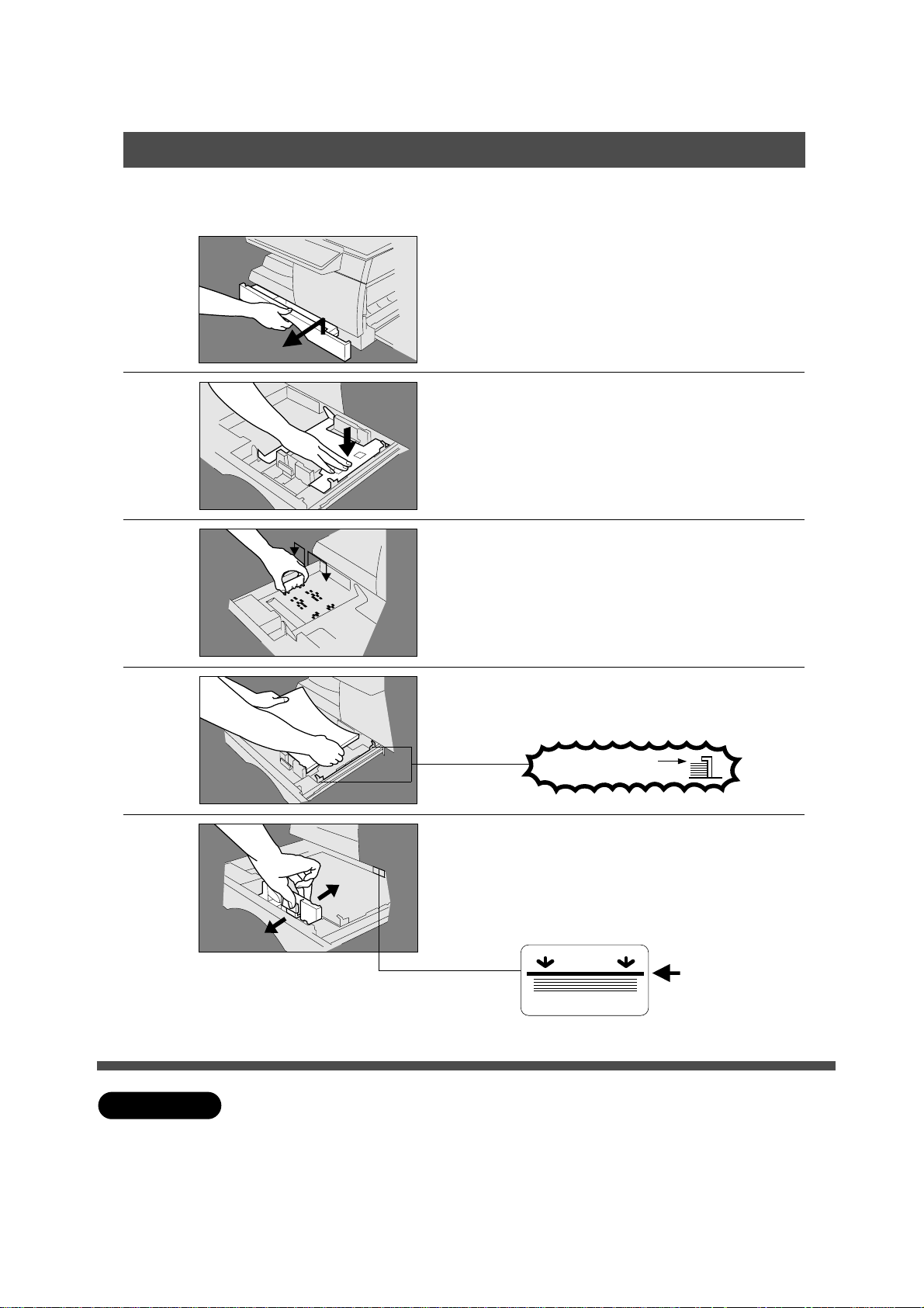
Install paper
■■
■
Push the paper tray into copier. Plug in the unit and turn on the power. When
■■
the Add Paper Indicator (
JJ
J) lights, install paper using the following procedure.
JJ
Lift slightly and pull paper tray out
of copier until it stops.
1
Push the bottom plate down until it
locks.
2
Install the paper guide into the
holes that correspond to the paper
3
size you plan to load.
4
5
ATTENTION
Place paper.
Up to 250 sheets.
Do not fill above
# Slide the paper guide (front) to
the paper edge.
$ Push the paper tray back into
copier.
Overfill Indicator
1-sided copy
Set-up is completed. No w ready to mak e a cop y.
C
When making 2-sided copies, use the sheet bypass.
C
If the paper tray is not closed completely, the Add Paper Indicator in the control
panel will light up. In that case, please close the paper tra y completely.
C
For changing paper size , see page 19.
6
Page 7
Setup Procedure
Connecting Printer Cable and Telephone Line
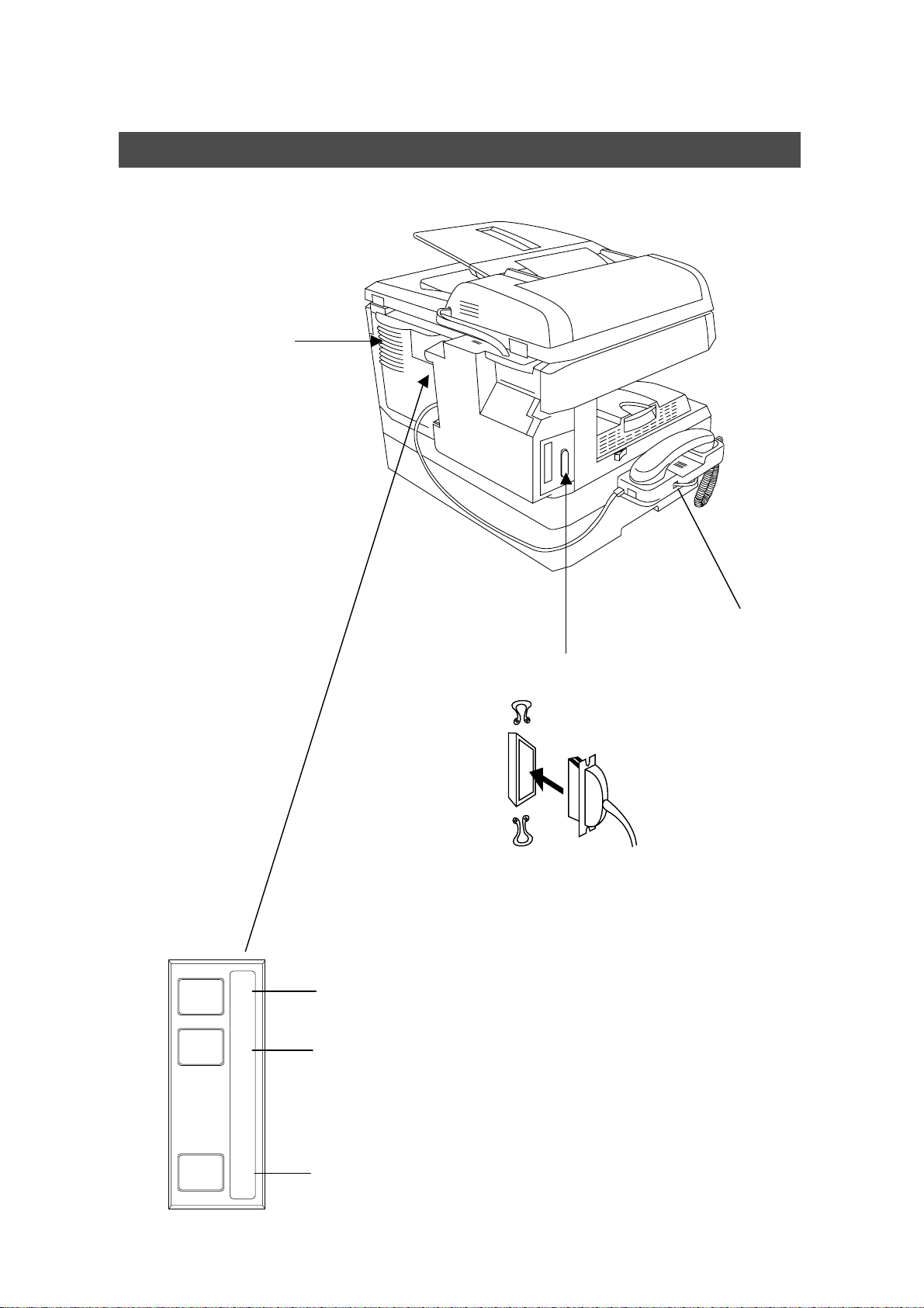
■■
■ Back & Left Side View
■■
Ventilation Openings
C
Do not block the v entilation
openings.
LINETEL
Handset (Option)
Parallel Interface Connector
C
Connect to PC
Parallel Interface Cable
C
Obtain a cable conforming to a PC separately.
(A cable does not come with the unit.) Use a cable of
IEEE1284 specifications, with a maximum length of 6 ft.
Telephone Line Modular Jack (LINE)
C
Connect to a leased line from telephone company.
TModular Jack for a Telephone Set independent from
DP-150 series
C
To be connected with the non-DP-150 use telephone.
HANDSET
Optional Modular Jack for an Optional Telephone
Handset.
7
Page 8
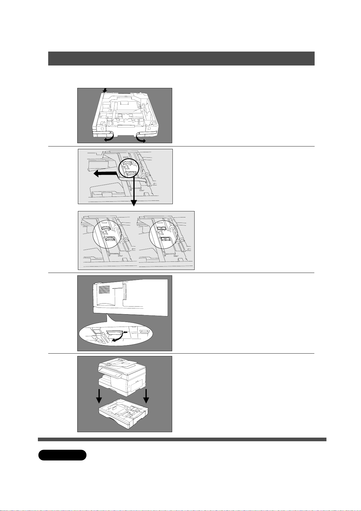
Setup Procedure For Option
2nd Cassette Module
■■
■ Unplug the power code when installing the 2nd cassette module
■■
Remove the tapes. (3 pieces)
1
Remove the tape as the arrow
shows.
2
Right Position Wrong Position
Make sure that the roller is on the
right position as shown left.
(The jagged side is up.)
If the position is wrong, adjust the
rollers the right position.
3
4
ATTENTION
Press the button of the white rear
cover then remove the cover.
Place the machine on the 2nd
cassette module.
C
Unplug the power code when installing each unit.
8
Page 9
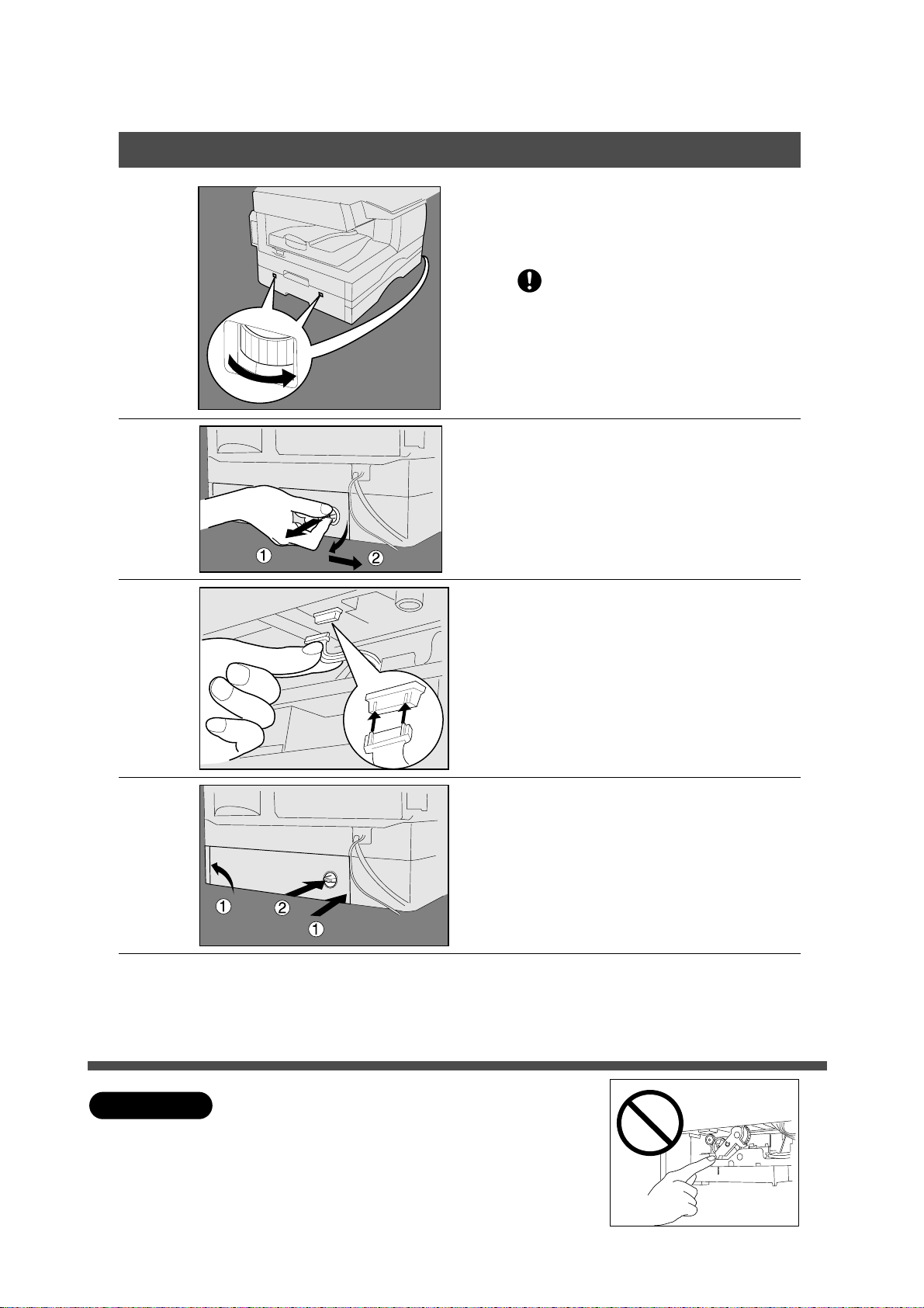
Setup Procedure For Option
2nd Cassette Module
5
Fix the 2nd cassette module under
the machine by turning the gears.
(Total 4 points)
If the 2nd cassette module is not
fixed securely, it may fall and hurt
you.
Remove the rear cover of the 2nd
cassette module.
6
7
8
# Pull out the hook.
$ Open the cover slightly, and
remove it.
Plug the harness of the 2nd
cassette module into the machine
connector.
# Reinstall the rear cover.
$ Insert the hook untill it locks.
-1
-2
9
ATTENTION
Slide out the paper cassette and
remove the shipping materials.
(See steps 3, 4 on page 9)
C
Unplug the power code when installing each unit.
Do not touch the gear area of the 2nd cassette
module.
Reinstall the rear cover and insert the hook then
plug the power code.
9
Page 10
Setup Procedure For Option
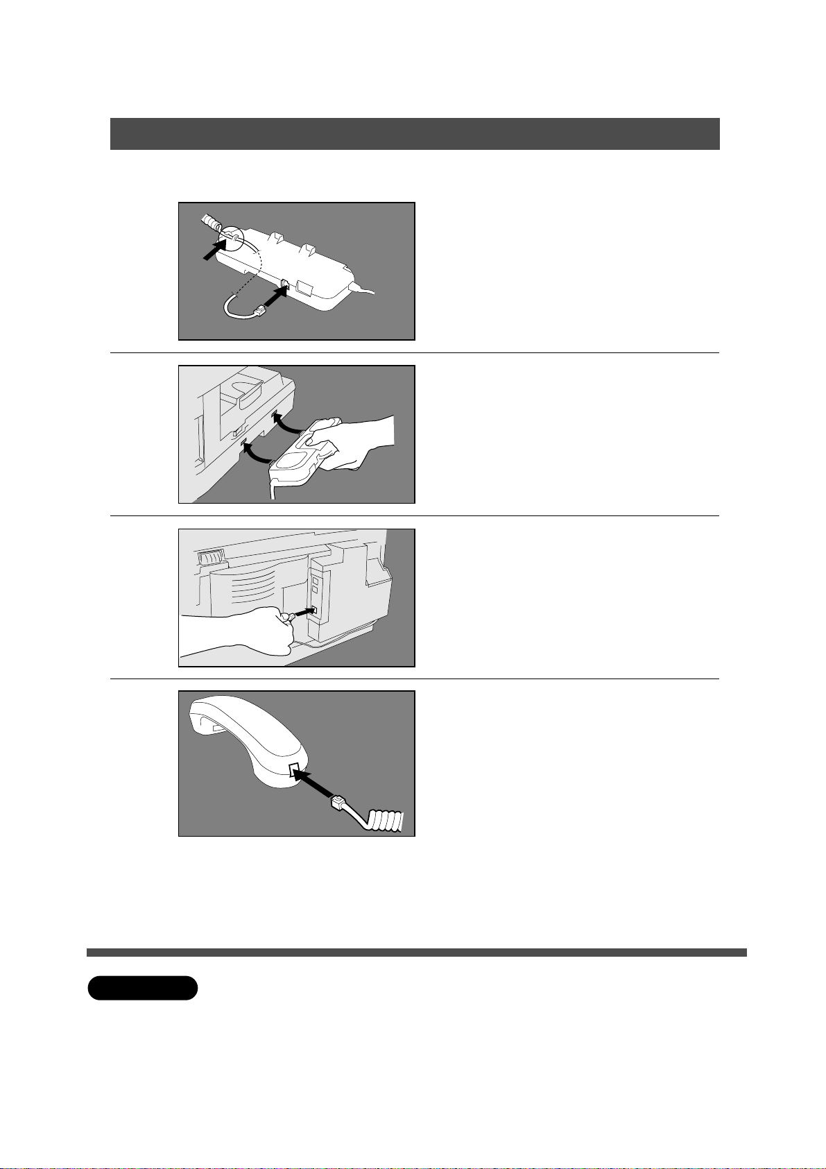
Handset Unit
■■
■ Unplug the power code when installing the handset-unit.
■■
Take the handset unit out of the
carton.
1
2
Connect the handset code to the
handset cradle.
Hook the projections into square
holes on the machine without
putting on the receiver.
3
4
Connect the cable into the
handset jack on the machine.
Connect the handset code into the
receiver.
Put the receiver on the cradle.
ATTENTION
C
Unplug the power code when installing the handset unit.
10
Page 11
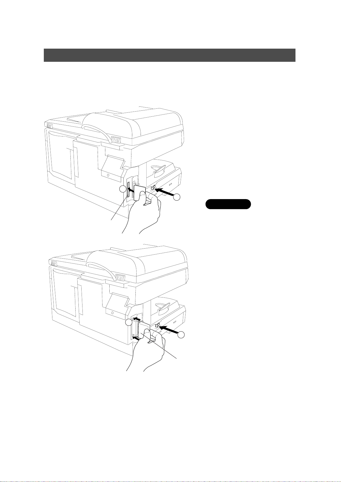
Setup Procedure For Option
Expansion Flash Memory Card
UE-410045 (1 MB)
UE-410046 (2 MB)
UE-410047 (4 MB)
2
Card Slot
(Copier left
rear side)
# Turn the Power Switch OFF.
$ Install the memory card
into the card slot.
C
Printed face side to forward.
1
CAUTION
C
Do not install or remove the
memory card white the power
switch ON.
# Install the memory card
cover.
$ Turn the Power Switch
ON.
3
4
Memory
Card Cover
11
Page 12
Installing Printer Driver
Windows 95/98
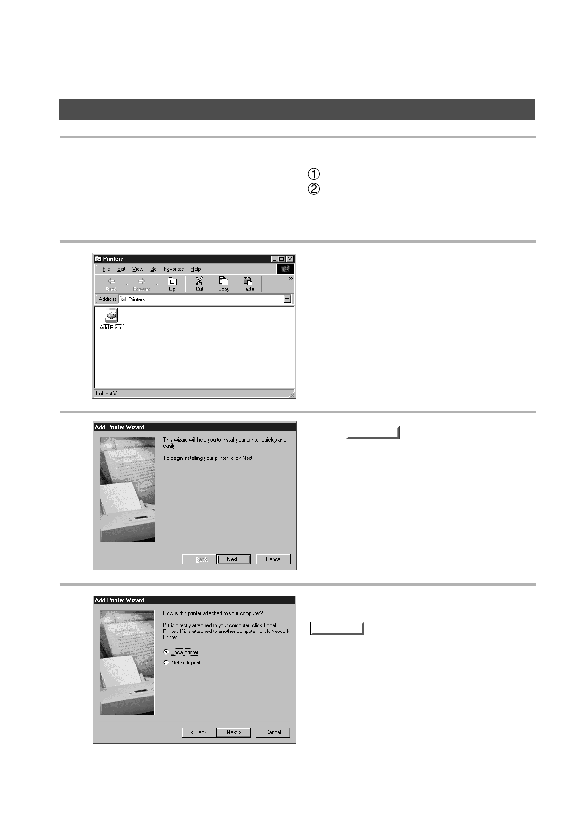
Open Printer dialog box.
1
Click Start key.
Place cursor on Settings and click Printers.
Double-click Add Printer icon.
2
3
4
Click key.
Select Local printer and click
Next
key.
• Network printer is specified when a printer on the
network is installed.
Refer to Windows 95/98 users' manual for
details.
Next
12
Page 13
Installing Printer Driver
Windows 95/98
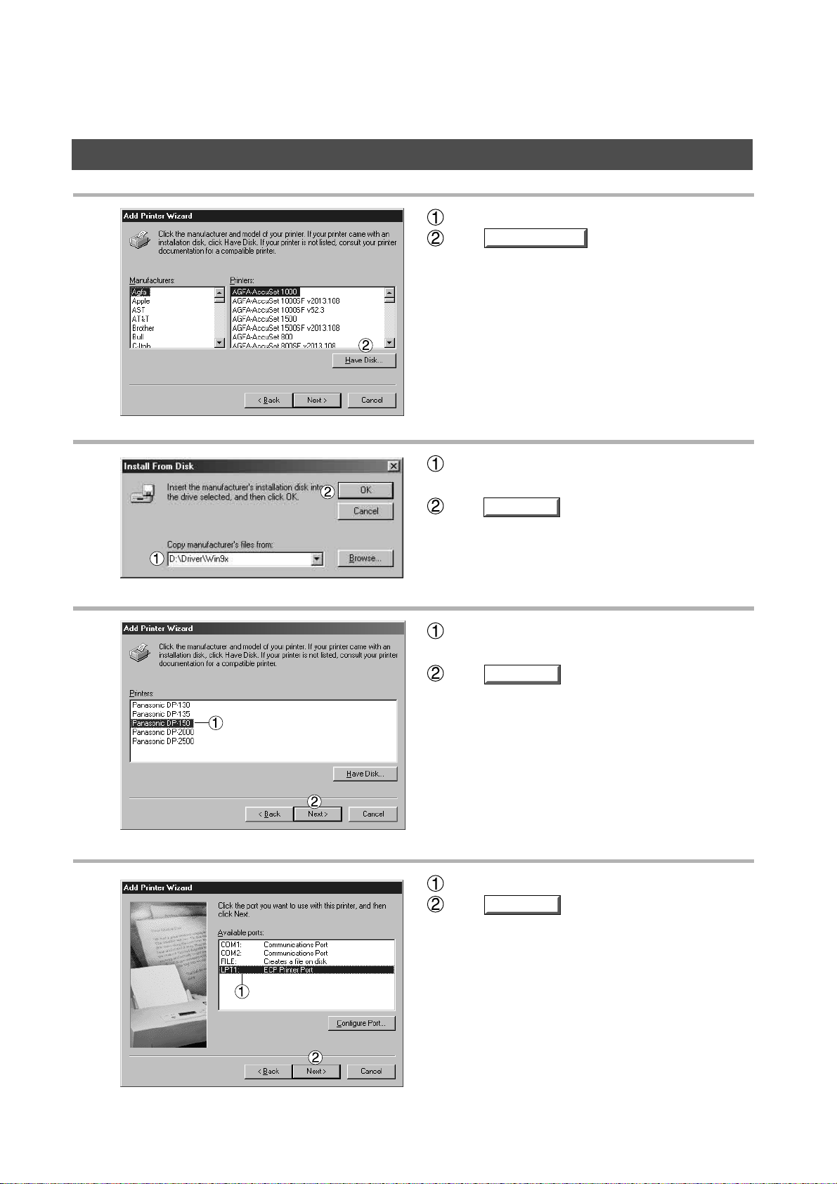
5
6
Insert CD-ROM containing printer driver.
Click key.
Specify drive name and type D:\Driver\Win9x.
(When drive D is CD-ROM drive.)
Click key.
Have Disk...
OK
7
8
Select device (Panasonic DP-130, 135 or
Panasonic DP-150).
Click key.
Select LPT1.
Click key.
Next
Next
13
Page 14

Installing Printer Driver
Windows 95/98
9
10
In response to Do you want your Windows-
based programs to use this printer as the
default printer?, select Yes or No.
Click key.
Required files are copied.
Finish
Icons are displayed in Printer window and become
available.
NOTE
• Be sure to delete drivers of earlier version before updating drivers.
• Restart Windows after updating drivers.
14
Page 15

Installing Printer Driver
Windows NT 4.0
Log in using an account with the authority to change system settings (e.g. Administrator).
Open Printer dialog box.
1
Click Start key.
Place cursor on Settings and click Printers.
Double-click Add Printer icon.
2
3
Select My Computer and then
click key.
Network printer server is specified when a printer
on the network server is installed.
Refer to Windows NT 4.0 users' manual for
details.
Next
15
Page 16

Installing Printer Driver
Windows NT 4.0
4
5
Select printer port and click
Next
key.
Insert CD-ROM containing printer driver.
Click key.
Have Disk...
6
7
Specify drive name and type D:\Driver\WinNT4.
(When drive D is CD-ROM drive.)
Click key.
Select device (Panasonic DP-130, 135 or
Panasonic DP-150).
Click key.
OK
Next
16
Page 17

Installing Printer Driver
Windows NT 4.0
8
9
In response to Do you want your Windows-
based programs to use this printer as the
default printer?, select Yes or No.
Click key.
Select Not Shared and click
Next
key.
Select Shared only when installing on network
server.
See Windows NT 4.0 users' manual for details.
Next
10
Select Yes [recommended] and click
Finish
key.
Test printing starts.
Default (initial setting) for paper size is A4 .
Select No when skipping test printing, and click
key.
Finish
17
Page 18

Installing Printer Driver
Windows NT 4.0
11
DP-150
Required files are copied.
Icons are displayed in Printer window and become
available.
NOTE
Notes:
Be sure to delete drivers of earlier version before updating drivers.
Restart Windows after updating drivers.
18
Page 19

Installing Printer Driver
Windows 2000
Log in using an account with the authority to change system settings (e.g. Administrator).
About Windows 2000
Panasonic has performed operation tests on Document Scanner, Status Monitor and Printing System
using Office 2000. However, the company does not necessarily guarantee normal operation of all
applications on Windows 2000.
Panasonic has not registered Windows 2000 logo. Ignore a warning message about logo upon installation.
Windows 2000 is capable of disallowing installation of drivers without logo registration. If the function has
been activated, cancel the function for installation. Operation manuals of this software package do not
cover operation of Windows 2000. See descriptions about Windows NT4.0.
Open Printer dialog box.
1
Click Start key.
Place cursor on Settings and click Printers.
2
3
Double-click Add Printer icon.
Click key.
Next
19
Page 20

Installing Printer Driver
Windows 2000
4
Select Local Printer and click
Next
key.
Specify Network Printer for installing a printer on
server upon network. Refer to manual about
Windows 2000.
5
6
Click key.
Select Printer Port and click
Next
.
Next
7
20
Insert a CD-ROM containing printer driver.
Click key.
Have Disk...
Page 21

Installing Printer Driver
Windows 2000
8
9
Specify drive name and type D:\ Driver \ Win
NT4. (When drive D is CD-ROM drive.)
Click key.
Select your device (Panasonic DP-130, 135 or
Panasonic DP-150).
Click key.
OK
Next
10
11
Panasonic DP-150
Click key.
Select Do not share this
Printer and click key.
Select Share as only when installing onto
network server. Refer to manual of Windows
2000 for details.
Next
Next
21
Page 22

Installing Printer Driver
Windows 2000
12
13
150
150
Select No and click key.
Click key.
Finish
Next
14
Click key.
Yes
22
Page 23

Installing Printer Driver
Windows 2000
15
Required files are copied.
Icons are displayed in Printer window and become
available.
23
Page 24

Installing the Document Management System
Insert provided CD-ROM.
1
2
3
Click key.
Click Panasonic-DMS.
Next
4
5
Verify installation destination
and click
Click Standard.
Next
key.
24
Page 25

Installing the Document Management System
Enter program folder name and
6
click key.
Required files are copied.
Next
7
8
Click key.
Panasonic Document Management System folder
is added to Start menu, and installation is
completed.
Finish
25
Page 26

Installing the Document Management System
NOTE
When installing on Windows NT4.0, log in using an account with the authority to
change system settings (e.g. Administrator).
Standard installation method installs all of the following drivers and applications.
Selecting custom installation allows selected installation of scanner and MFP utility
individually.
- Scanner
Document Scanner (TWAIN scanner driver)
- Manager
Document Manager (Image management application)
Document Viewer (Image editing application)
- MFP utility
Status monitor (Device status monitor)
Configuration Editor
Phone Book Editor
By installing this software, the system selects LPT1 as a parallel port to be connected
to a device. For connecting a device to a port other than LPT1, change connection
ports by selecting [Panasonic], [Panasonic Document Management System], and [Port
Selection Utility] from Start menu.
Before updating software, be sure to delete old version software.
Take the following steps to install software on Windows 2000:
1. For installation, log in using an account with the authority to change system settings
(e.g. Administrator).
2. Restart Windows after completion of installation.
3. After restart, log in again using an account with the authority to change system
settings (e.g. Administrator).
4. After completion of installation, normal operation is enabled by logging in with
ordinary user account.
26
Page 27

Installing Panasonic Class 2 Fax Modem
Windows 95/98
The installation is required for transmitting/receiving FAX with a PC via digital image integrator, using
general-purpose PC fax function software (recommended: WinFax).
Class 2 Fax Modem
Select Settings from the Start
1
menu and open the control
panel.
2
Double-click .
Click .
Next
Add New Hardware
27
Page 28

Installing Panasonic Class 2 Fax Modem
3
4
(Windows 98 only)
Click .
Select No, the device isn't in the list.
Click .
Next
Next
(Windows 98 only)
Select No, I want to select the hardware from
a list.
Click .
Next
28
Page 29

Installing Panasonic Class 2 Fax Modem
Select Ports (COM&LPT).
Click .
5
Select Communications Port.
Click .
6
Next
Have Disk...
7
Click .
8
Click .
9
Click .
10
Click and restart PC.
11
Enter D:\Setup.
D: means CD-ROM drive on PC. Drive name depends on the PC.
Click .
OK
Next
Next
Finish
Yes
29
Page 30

Installing Panasonic Class 2 Fax Modem
Repeat steps from "1" to "3."
12
Select No, the device isn't in the list.
Click .
13
Next
14
Select No, I want to select the hardware from
a list.
Click .
Select Modem.
Click .
Next
Next
30
Page 31

Installing Panasonic Class 2 Fax Modem
Select Don't detect my modem; I will select it
15
from a list.
Click .
Enter D:\Setup.
D: means CD-ROM drive on PC.
16
Click .
Next
Drive name depends on the PC.
OK
17
18
Select Panasonic DP-130 or DP-150 Class 2
Fax Modem.
Click .
Select Panasonic MFP Redirected Com Port
(COM4*).
* COM number depends on the PC.
Click .
Next
Next
31
Page 32

Installing Panasonic Class 2 Fax Modem
19
Click .
Installation of modem is completed.
Finish
32
Page 33

Installing Panasonic Class 2 Fax Modem
Windows NT 4.0
Install Panasonic Class 2 Fax Modem. The installation is required for transmitting/receiving FAX with a PC
via digital image integrator, using general-purpose PC fax function software (recommended: WinFax).
Class 2 Fax Modem
Select Settings from the Start menu and open the control
1
panel.
Double-click Modems.
2
3
4
Select Don't detect my modem; I will select it
from a list.
Click .
Click .
Next
Have Disk...
33
Page 34

Installing Panasonic Class 2 Fax Modem
Enter D:\Setup.
5
6
D: means CD-ROM drive on PC.
Drive name depends on the PC.
Click .
Select Panasonic DP-130 or DP-150 Class
2 Fax Modem.
Click .
OK
Next
7
8
Select a COM port shown at the bottom of the
COM ports list.
Click .
Click .
Installation of modem is completed.
Next
Finish
34
Page 35

Installing Panasonic Class 2 Fax Modem
Close Modems Properties
9
screen.
35
Page 36

Installing Panasonic Class 2 Fax Modem
Windows 2000
Install Panasonic Class 2 Fax Modem. The installation is required for transmitting/receiving FAX with a PC
via digital image integrator, using general-purpose PC fax function software (recommended: WinFax).
Class 2 Fax Modem
Select Settings from the Start menu and open the control
1
panel.
2
Double-Click Add/Remove
Hardware.
3
4
Click .
Select Add/Troubleshoot a device.
Click .
Next
Next
36
Page 37

Installing Panasonic Class 2 Fax Modem
5
6
Select Add a new device.
Click .
Select No, I want to select the hardware
from a list.
Click .
Next
Next
7
Select Modems.
Click .
Next
37
Page 38

Installing Panasonic Class 2 Fax Modem
Select Don't detect my modem; I will select
8
it from a list.
Click .
Next
9
10
Click .
Enter D:\Setup.
D: means CD-ROM drive on PC.
Drive name depends on the PC.
Click .
Have Disk...
OK
38
Page 39

Installing Panasonic Class 2 Fax Modem
11
12
Select Panasonic DP-130 or DP-150
Class 2 Fax Modem.
Click .
Select COM2.
Click .
Next
Next
39
Page 40

Installing Panasonic Class 2 Fax Modem
13
If warning message for logo certification
appears, click and continue
installation.
Yes
Click .
Installation of modem is completed.
Finish
40
Page 41

U.S.A. only
WARRANTY
“PANASONIC DOCUMENT IMAGING COMPANY MAKES NO W ARRANTIES , GU ARANTEES OR
REPRESENTATIONS, EXPRESSED OR IMPLIED , TO CUSTOMER WITH RESPECT T O THIS
PANASONIC COPIER, INCLUDING BUT NOT LIMITED T O , ANY IMPLIED WARRANTY OF
MERCHANTABILITY OR FITNESS FOR A PARTICULAR PURPOSE.
PANASONIC DOCUMENT IMAGING COMPANY ASSUMES NO RISK AND SHALL NO T BE SUBJECT
TO LIABILITY FOR ANY DAMAGE, INCLUDING, BUT NO T LIMITED T O DIRECT, INDIRECT, SPECIAL,
INCIDENTAL OR CONSEQUENTIAL DAMAGES OR LOSS OF PR OFITS SUSTAINED BY THE
CUSTOMER IN CONNECTION WITH THE USE OR APPLICATION OF THIS PANASONIC COPIER. SEE
YOUR DEALER FOR DETAILS OF DEALER’S WARRANTY. ”
For Service Call:
Panasonic Document Imaging Company
A Division of Matsushita Electric Corporation of America
Two Panasonic Way
Secaucus, New Jersey 07094
Panasonic Canada Inc.
5770 Ambler Drive, Mississauga,
Ontario L4W 2T3
FFPTD1041 S0800-0
August 2000
Printed in Japan
 Loading...