

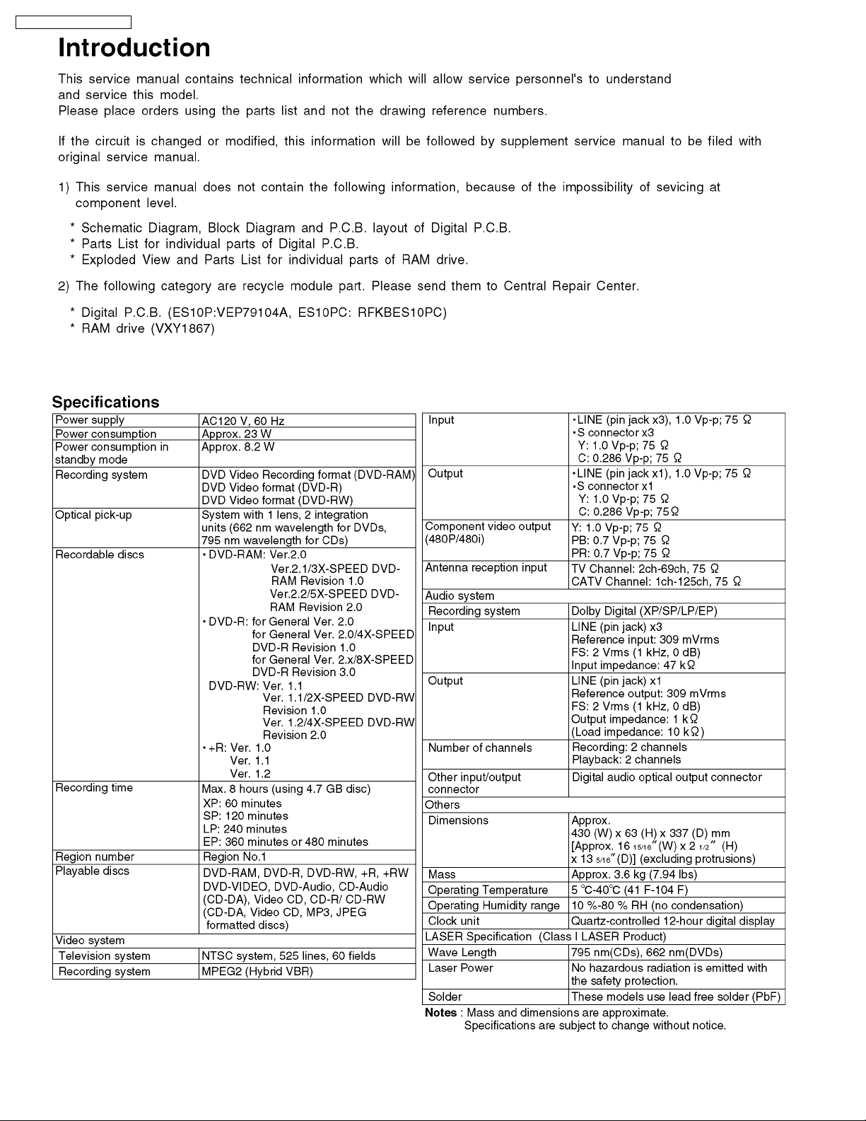
Panasonic DMR-ES10P, DMR-ES10PC Service Manual
DVD Video Recorder
DMR-ES10P
DMR-ES10PC
Vol. 1
Colour
(K).......................Black Type
(S).......................Silver Type
ORDER NO.DSD0502037C1
B24
© 2005 Matsushita Electric Industrial CO., Ltd. All
rights reserved. Unauthorized copying and
distribution is a violation of law.
DMR-ES10P / DMR-ES10PC
2

DMR-ES10P / DMR-ES10PC
CONTENTS
Page Page
1 Safety precautions 4
1.1. General guidelines
1.2. Caution for fuse replacement
2 Prevention of Electrostatic Discharge (ESD) to Electrostatic
Sensitive (ES) Devices
3 Precaution of Laser Diode
4 Handling the Lead-free Solder
4.1. About lead free solder (PbF)
5 Each Button
6 New Feature
6.1. Quick start function(REC)
7 Taking out the Disc from RAM-Drive Unit when the Disc
cannot be ejected by OPEN/CLOSE button
7.1. Forcible Disc Eject
7.2. When the Forcible Disc Eject can not be done.
8 Service Explorer
9 Self-Diagnosis and Special Mode Setting
9.1. Self-Diagnosis Functions
9.2. Special Modes Setting
9.3. Service Modes
10 Assembling and Disassembling
10.1. Disassembly Flow Chart
10.2. P.C.B. Positions
10.3. Top Cover
10.4. Front Panel
10.5. Digital P.C.B.
10.6. DVD-RAM Drive
10.7. Power P.C.B.
10.8. Rear Panel
10.9. Front (L) P.C.B.
10.10. Main P.C.B.
11 Service Fixture and Tools
12 Service Positions
12.1. Checking and Repairing of Power P.C.B.
12.2. Checking and Repairing of Digital P.C.B.
12.3. Checking and Repairing of Main P.C.B.
12.4. Checking and Repairing of DVD-RAM Drive
13 Caution after replacing parts
10
13
13
14
16
19
19
19
20
20
20
21
21
21
22
22
23
23
23
24
25
26
27
4
4
5
6
6
6
7
8
8
9
9
9
13.1. After replacing the RAM Drive with new one
13.2. When the unit does not operate normally after replacing
the Timer Microprocessor or Main P.C.B.
14 Standard Inspection Specifications after Making Repairs
15 Voltage and Waveform Chart
15.1. Power P.C.B.
15.2. Main P.C.B.
15.3. Tuner P.C.B.
15.4. P9001 Connector
15.5. Waveform Chart
16 Abbreviati ons
17 Block Diagram
17.1. Power Supply Block Diagram
17.2. Analog Video Block Diagram
17.3. Analog Audio Block Diagram
17.4. Analog Timer Block Diagram
18 Schematic Diagram
18.1. Interconnection Schematic Diagram
18.2. Main Power Supply Schematic Diagram
18.3. Sub Power Section (Main P.C.B. (1/5)) Schematic
Diagram (P)
18.4. Main Net Section (Main P.C.B. (2/5)) Schematic Diagram
(M)
18.5. Video I/O Section (Main P.C.B. (3/5)) Schematic Diagram
(V)
18.6. Audio Main Section (Main P.C.B. (4/5)) Schematic
Diagram (A)
18.7. Timer Section (Main P.C.B. (5/5)) Schematic Diagram (T)
18.8. Tuner Pack Schematic Diagram
19 Print Circuit Board
19.1. Power P.C.B.
19.2. Main P.C.B.
19.3. Tuner P.C.B., Front (L) P.C.B.
20 Exploded Views
20.1. Casing Parts & Mechanism Section
20.2. Packing & Accessories Section
21 Replacement Parts List
27
27
27
28
28
28
30
30
31
32
35
35
37
38
39
41
41
42
43
44
45
47
48
50
51
51
52
57
59
59
60
61
3
DMR-ES10P / DMR-ES10PC
1 Safety precautions
1.1. General guidelines
1. When servicing, observe the original lead dress. If a short circuit is found, replace all parts which have been overheated or
damaged by the short circuit.
2. After servicing, see to it that all the protective devices such as insulation barriers, insulation papers shields are properly
installed.
3. After servicing, make the following leakage current checks to prevent the customer from being exposed to shock hazards.
1.1.1. Leakage current cold check
1. Unplug the AC cord and connect a jumper between the two
prongs on the plug.
2. Measure the resistance value, with an ohmmeter, between
the jumpered AC plug and each exposed metallic cabinet
part on the equipment such as screwheads, connectors,
control shafts, etc. When the exposed metallic part has a
return path to the chassis, the reading should be between
1MΩand 5.2MΩ.
When the exposed metal does not have a return path to
the chassis, the reading must be
Figure 1
.
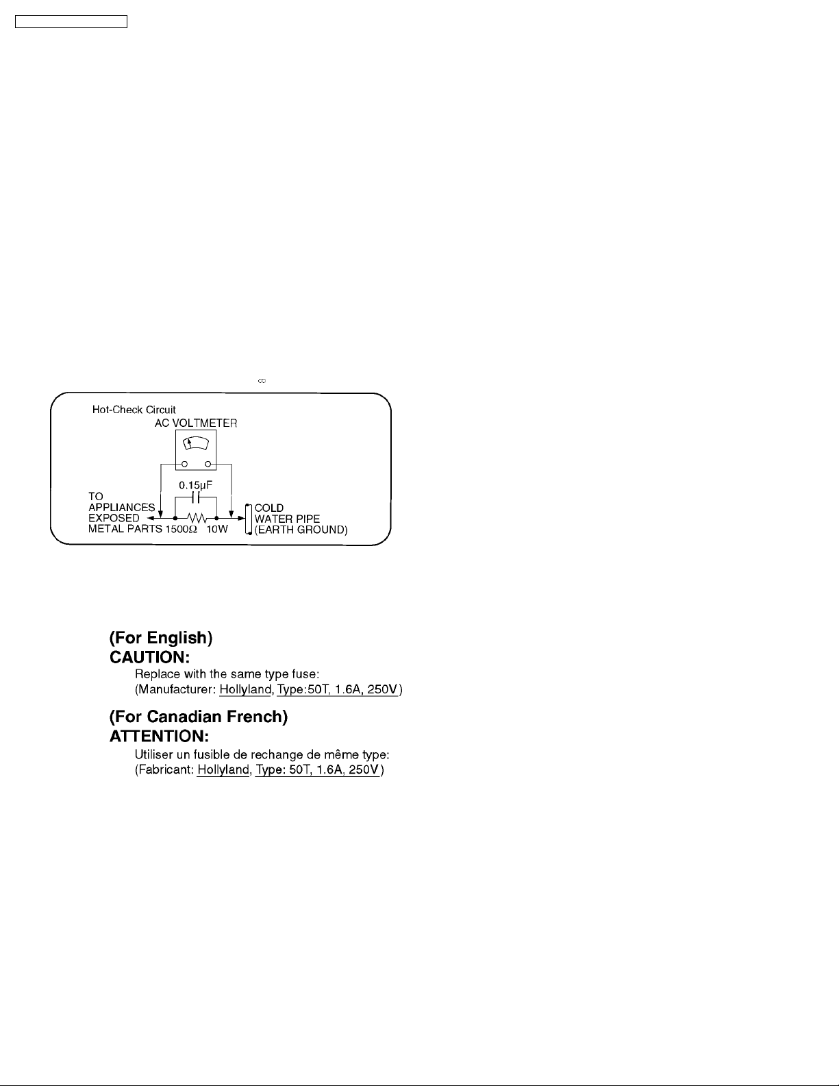
1.1.2. Leakage current hot check
(See Figure 1 .)
1. Plug the AC cord directly into the AC outlet. Do not use an
isolation transformer for this check.
2. Connect a 1.5kΩ, 10 watts resistor, in parallel with a 0.15µF
capacitors, between each exposed metallic part on the set
and a good earth ground such as a water pipe, as shown in
Figure 1.
3. Use an AC voltmeter, with 1000 ohms/volt or more
sensitivity, to measure the potential across the resistor.
4. Check each exposed metallic part, and measure the
voltage at each point.
5. Reverse the AC plug in the AC outlet and repeat each of the
above measurements.
6. The potential at any point should not exceed 0.75 volts
RMS. A leakage current tester (Simpson Model 229 or
equivalent) may be used to make the hot checks, leakage
current must not exceed 1/2 milliampere. In case a
measurement is outside of the limits specified, there is a
possibility of a shock hazard, and the equipment should be
repaired and rechecked before it is returned to the
customer.
1.2. Caution for fuse replacement
4
DMR-ES10P / DMR-ES10PC
2 Prevention of Electrostatic Discharge (ESD) to
Electrostatic Sensitive (ES) Devices
Some semiconductor (solid state) devices can be damaged easily by static electricity. Such components commonly are called
Electrostatic Sensitive (ES) Devices. Examples of typical ES devices are integrated circuits and some field-effect transistor-sand
semiconductor "chip" components. The following techniques should be used to help reduce the incidence of component damage
caused by electrostatic discharge (ESD).
1. Immediately before handlin g any semiconductor component or semiconductor-equipped assembly, drain off any ESD on your
body by touching a known earth ground. Alternatively, obtain and wear a commercially available discharging ESD wrist strap,
which should be removed for potential shock reasons prior to applying power to the unit under test.
2. After removing an electrical assembly equipped with ES devices, place the assembly on a conductive surface such as
aluminum foil, to prevent electrostatic charge buildup or exposure of the assembly.
3. Use only a grounded-tip soldering iron to solder or unsolder ES devices.
4. Use only an anti-static solder removal device. Some solder removal devices not classified as "anti-static (ESD protected)" can
generate electrical charge sufficient to damage ES devices.
5. Do not use freon-propelled chemicals. These can generate electrical charges sufficient to damage ES devices.
6. Do not remove a replacement ES device from its protective package until immediately before you are ready to install it. (Most
replacement ES devices are packaged with leads electrically shorted together by conductive foam, aluminum foil or comparable
conductive material).
7. Immediately before removing the protective material from the leads of a replacement ES device, touch the protective material
to the chassis or circuit assembly into which the device will be installed.
Caution
Be sure no power is applied to the chassis or circuit, and observe all other safety precautions.
8. Minimize bodily motions when handlin g unpackaged replacement ES devices. (Otherwise hamless motion such as the brushing
together of your clothes fabric or the lifting of your foot from a carpeted floor can generate static electricity sufficient to damage
an ES device).
5
DMR-ES10P / DMR-ES10PC
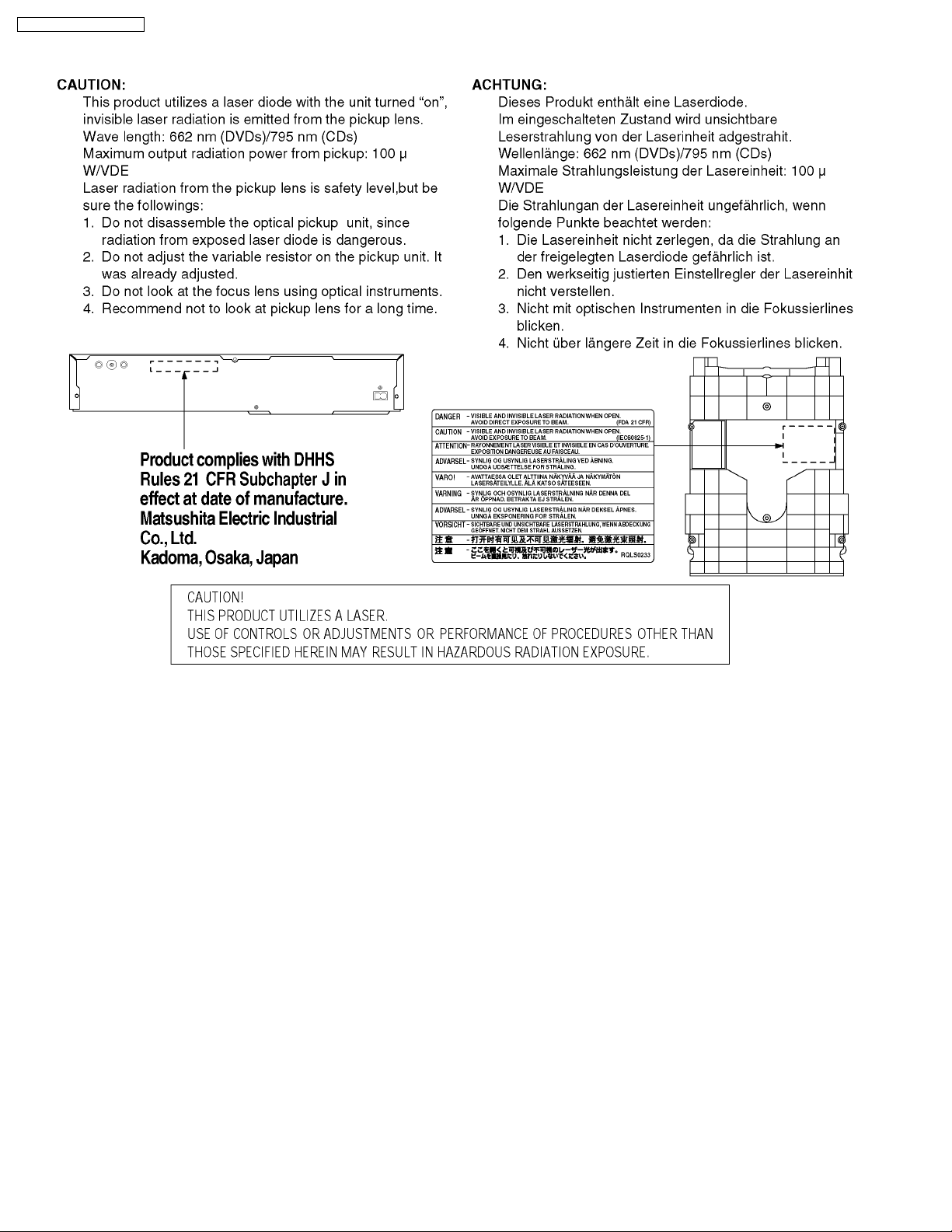
3 Precaution of Laser Diode
4 Handling the Lead-free Solder
4.1. About lead free solder (PbF)
Distinction of PbF P.C.B.:
P.C.B.s (manufactured) using lead free solder will have a PbF stamp on the P.C.B.
Caution:
Pb free solder has a higher melting point than standard
·
Please use a high temperature soldering iron. In case of the soldering iron with temperature control, please set it to 700 ±
20°F (370 ± 10°C).
· Pb free solder will tend to splash when heated too high (about 1100°F/600°C).
· W hen soldering or unsoldering, please completely remove all of the solder on the pins or solder area, and be sure to heat
the soldering points with the Pb free solder until it melts enough.
solder; Typically the melting point is 50 - 70°F (30 - 40°C) higher.
6
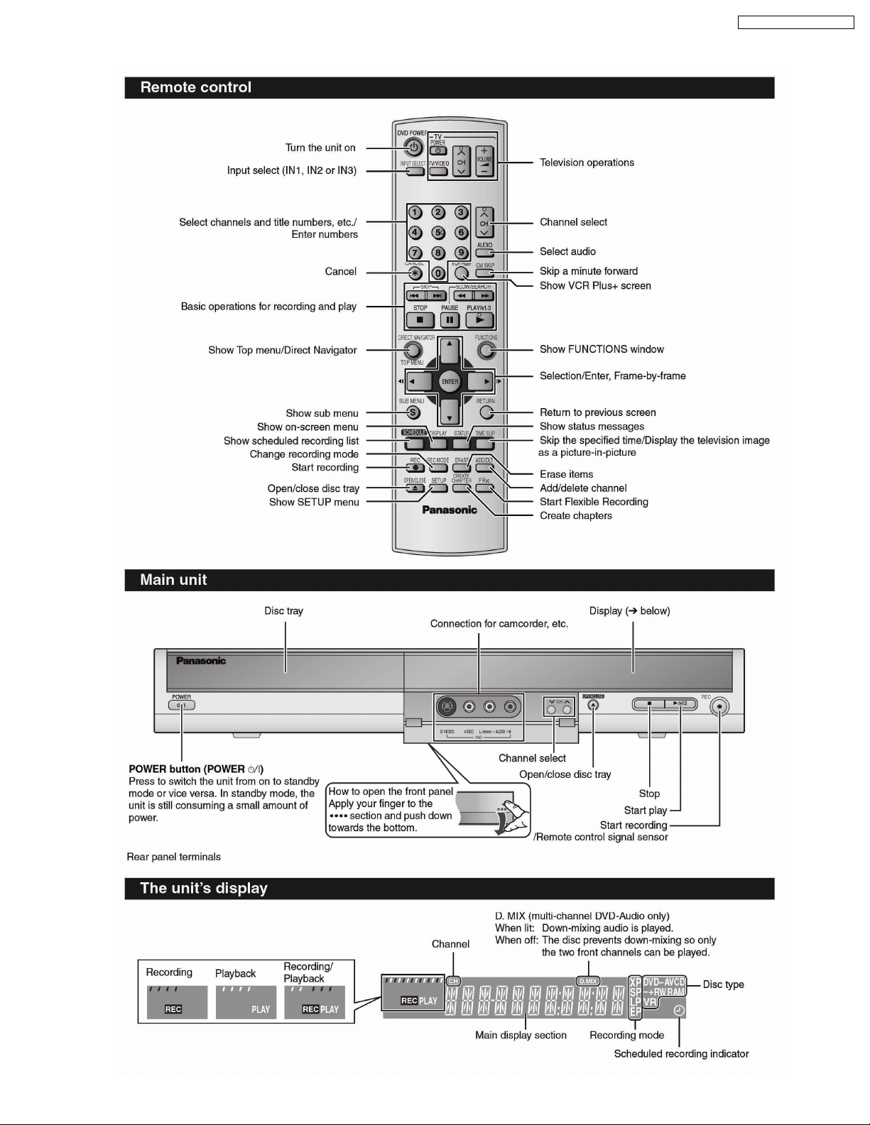
5 Each Button
DMR-ES10P / DMR-ES10PC
7
DMR-ES10P / DMR-ES10PC
6 New Feature
6.1. Quick start function(REC)
1. General
A few seconds after tuning on the unit,you can start recording to DVD-RAM,HDD.
You can switch the operation of this function (ON/OFF) on the menu screen. .
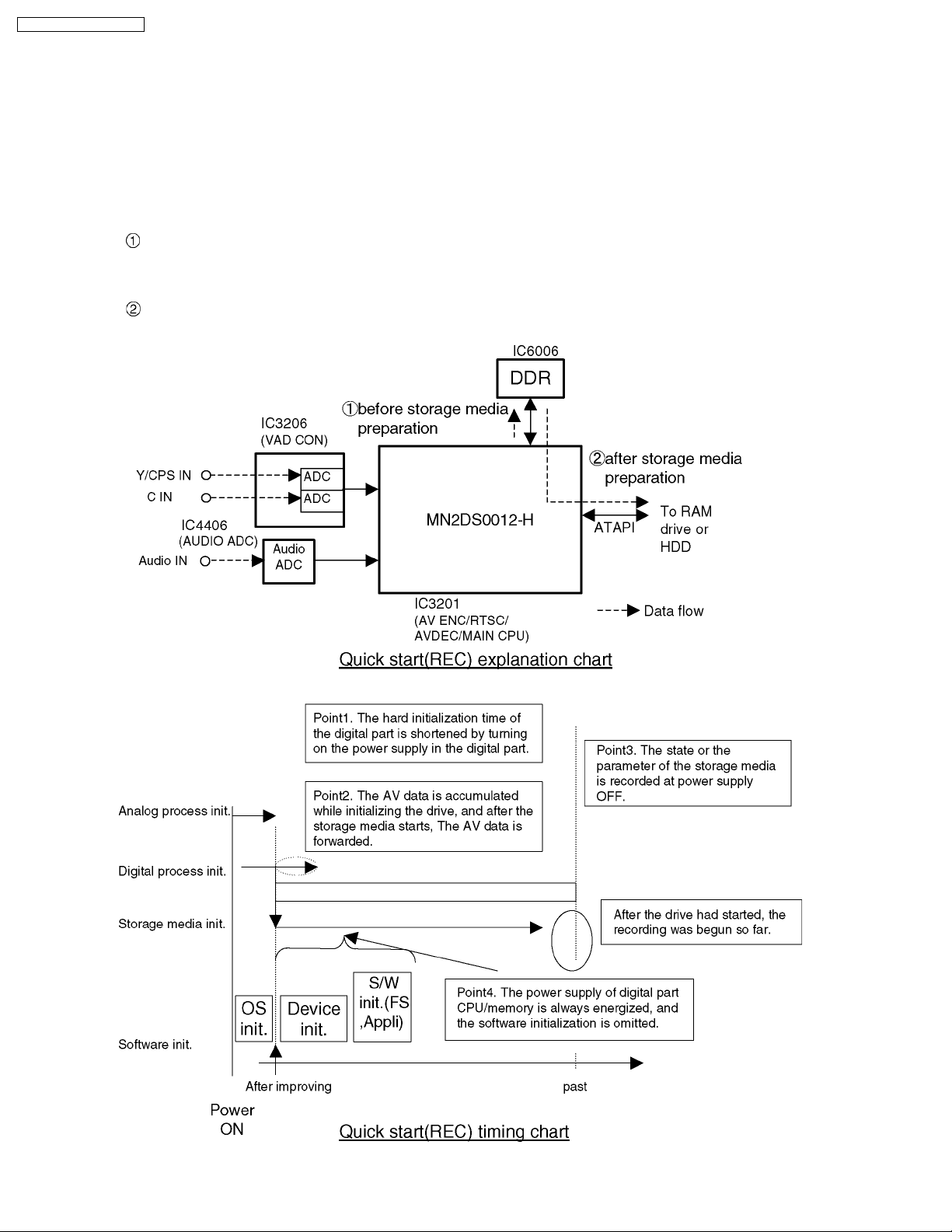
2. Quick start(REC) principle
In the power-off at Quick start, only power supplies for video IC,tuner and storage media are cut off.
When the REC button is pushed a few second after the power button is pushed, Audio and Video data are stored in
DDR SDRAM before a storage media(DVD-RAM or HDD) preparation.
*Preparation time → DVD-RAM: Fabout 8seconds
After a storage media(DVD-RAM or HDD) preparation,Audio and Video data are transfer from DDR SDRAM to the
storage media.
8
DMR-ES10P / DMR-ES10PC
7 Taking out the Disc from RAM-Drive Unit when the Disc
cannot be ejected by OPEN/CLOSE button
7.1. Forcible Disc Eject
7.1.1. When the power can be turned off.
1. Turn off the power and press [STOP] [CH UP] keys on the front panel simultaneously for 5 seconds.
7.1.2. When the power can not be turned off.
1. Press [POWER] key on the front panel for over 10 seconds to turn off the power forcibly, and press [STOP] [CH UP] keys on
the front panel simultaneousl y for 5 seconds.
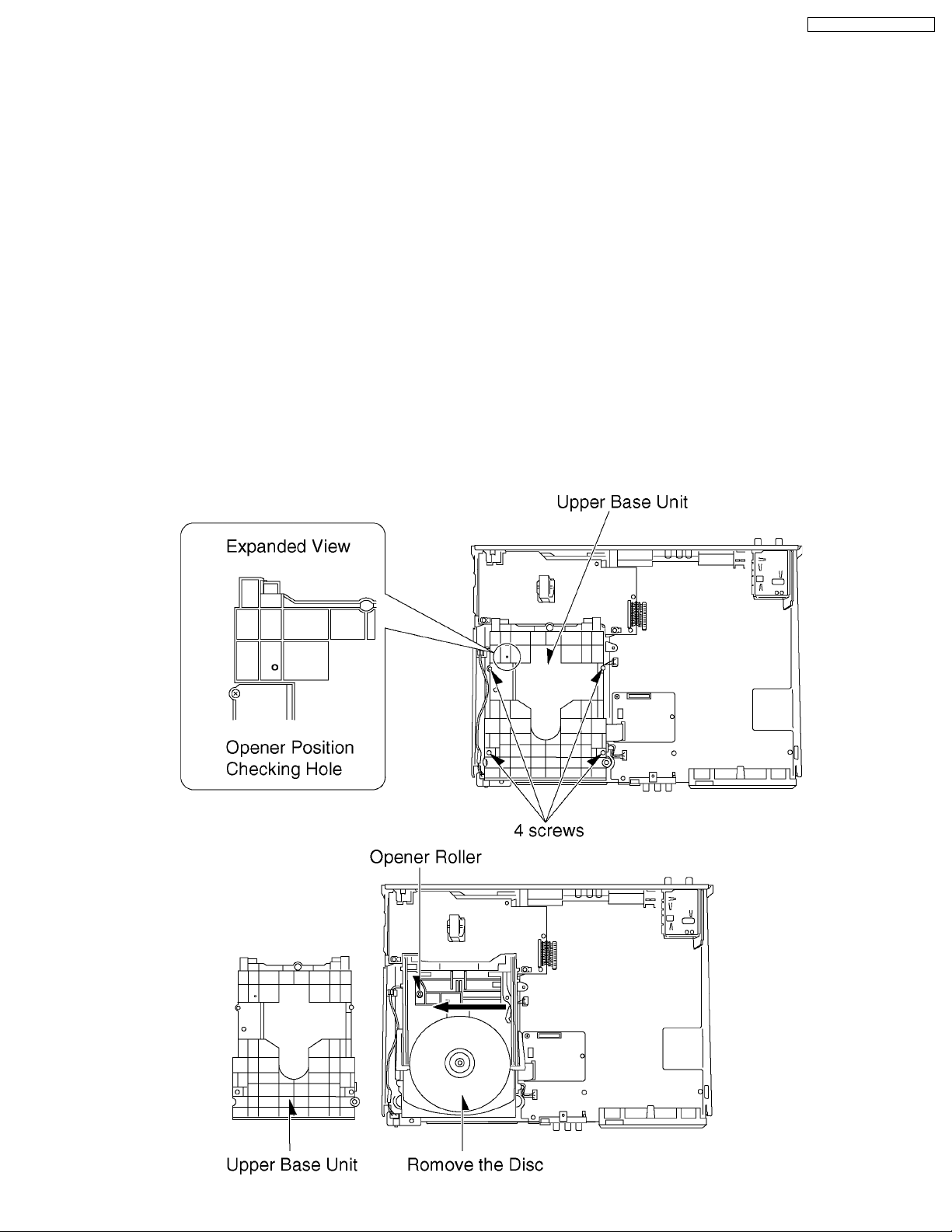
7.2. When the Forcible Disc Eject can not be done.
1. Turn off the power and pull out AC cord.
2. Remove the Top Case.
3. Remove the Front Panel.
4. Remove 4 screws and Upper Base Unit from DVD-RAM Drive.
5. Take out the disc and put the Opener Roller on fully position for direction of Arrow.
6. Put the Upper Base Unit so that the Opener Roller is inserted into the groove.
7. Check Opener Roller is seen through the Opener position Checking Hole, and tighten 4 screws.
9
DMR-ES10P / DMR-ES10PC
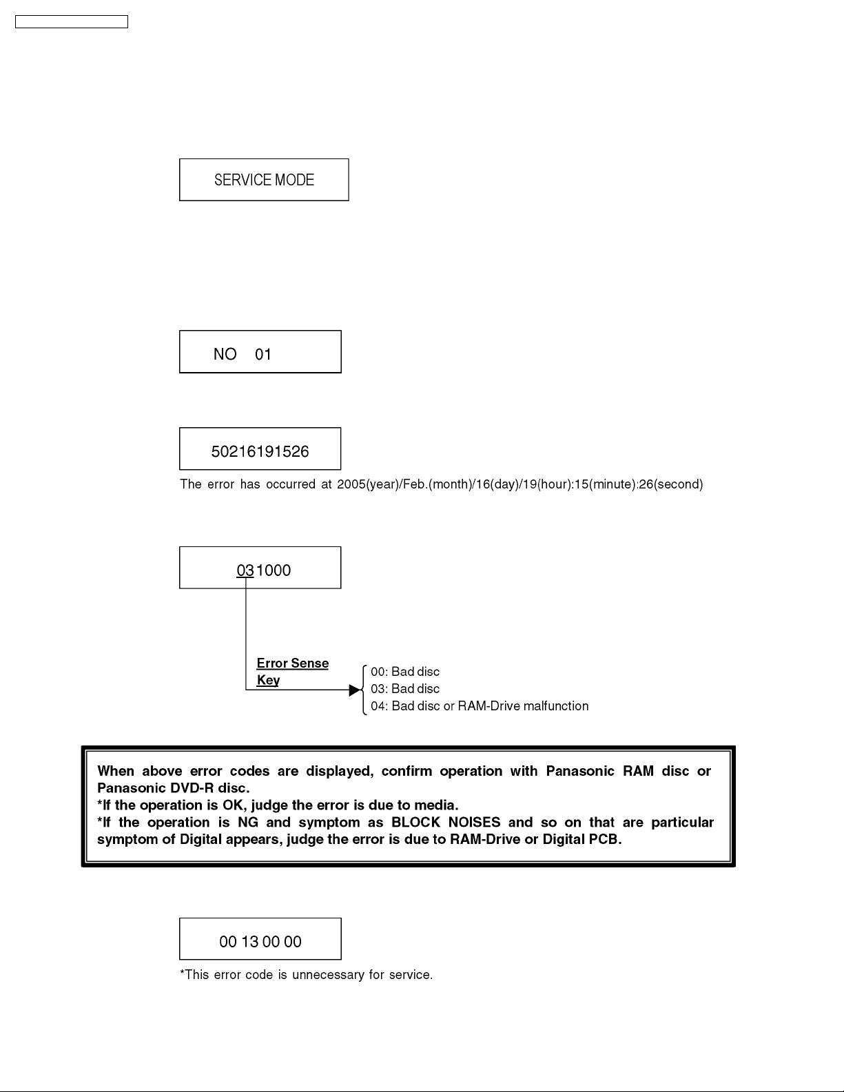
8 Service Explorer
Confirm “RAM-Drive Last Error” in Service Mode
Execute Service Mode
1. Press [REC], [CH UP] and [OPEN/CLOSE] simultaneously for 5 second s when P-off.
FL Display:
*After finishing display “(7). Factor of Drive Error occurring”, press [0] [2] ~[1] [9] keys of the Remote Controller so that
19 memories can be displayed as maximum.
2. Press [4] [2] keys of remote controller.
Example of FL Display:
(1) Error Number is displayed for 5 seconds.
(2) Time when the error has occurred is displayed for 5 seconds.
(3) Last Drive Error (1/2) is displayed for 5 seconds.
(4) Last Drive Error (2/2) is displayed for 5 seconds.
10
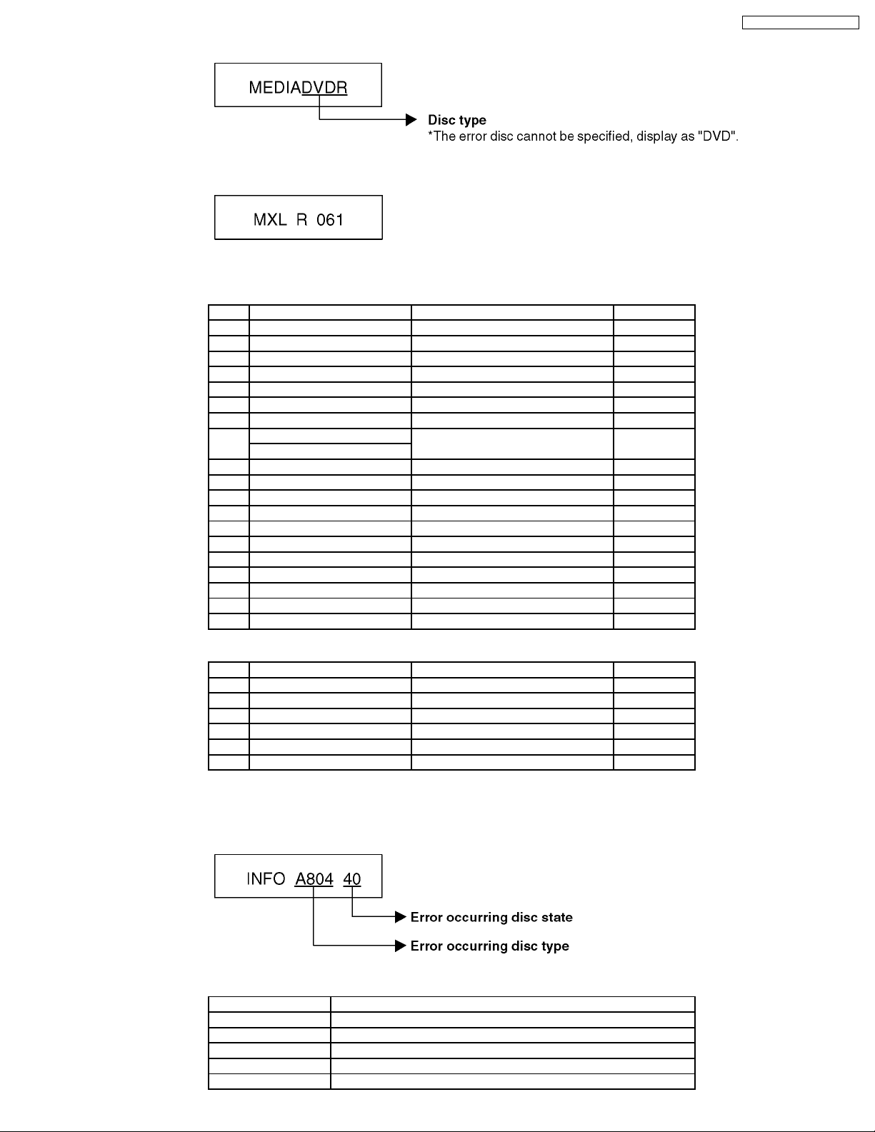
(5) Error occurring Disc type is display ed for 5 seconds.
(6) Disc Maker´s ID is displayed for 5 seconds.
Example of Disc Maker´s ID:
DVD-R Disc
No. FL Display (Disc Maker´s ID) Disc Maker Country
1 MEI Panasonic Japan
2 PVC Pioneer Japan
3 MCC Mitsubishi Chemical Corporation Japan
4 TDK TDK Japan
5 MXL Maxell Japan
6 MCI MITUI CHEMICALS Japan
7 JVC Victor JVC Japan
8 TAIYOYUDEN Taiyo yuden Japan
TYG
9 GSC Giga Storage Taiwan
10 PRODISC Prodisc Taiwan
11 PRINCO PRINCO Taiwan
12 RITEK RITEK Taiwan
13 OPTDISC OPTDISC Taiwan
14 LEAD DATA LEAD DATA Taiwan
15 CMC CMC Taiwan
16 AUVISTAR AUVISTAR Taiwan
17 ACER Acer Taiwan
18 VIVASTAR VIVASTAR Switzerland
19 LGE LG Electronics Korea
DMR-ES10P / DMR-ES10PC
DVD-RAM Disc
No. FL Display (Disc Maker´s ID) Disc Maker Country
1 MEI Panasonic
2 MATSUSHITA Panasonic Japan
3 MXL Maxell Japan
4 PRODISC Prodisc Taiwan
5 OPTDISC OPTDISC Taiwan
6 CMC CMC Taiwan
*Since an display is arbitrarily set up by the disk producer side, the above-mentioned display may be changed.
Please make it reference as an example of a display.
(7) Factor of Drive Error occurring is left display ed
Error Occurring Disc Type
FL Display Disc Type
00 DVD-ROM/Video
01 Audio-CD
02 2.6GB DVD-RAM
03 4.7GB DVD-RAM
04 DVD-R
11

DMR-ES10P / DMR-ES10PC
Error Occurring Disc State
12

DMR-ES10P / DMR-ES10PC
9 Self-Diagnosis and Special Mode Setting
9.1. Self-Diagnosis Functions
Self-Diagnosis Function provides information for errors to service personnel by “Self-Diagnosis Display” when any error has
occurred.
U**, H** and F** are stored in memory and held.
You can check latest error code by transmitting [0] [1] of Remote Controller in Service Mode.
Automatic Display on FL will be cancelled when the power is turned off or AC input is turned off during self-diagnosis display is ON.
Error Code Diagnosis contents Description Monitor Display Automatic FL display
U30 Remote control code error Display appears when main unit and remote
U59 Abnormal inner temperature
U99 Hang-up Displayed when communication error has
F00 No error information Initial setting for error code in memory
F58 Drive hardware error When drive unit error is detected, the event is
F34 Initialization error when main
UNSUPPORTUnsupported disc error *An unsupported format disc was played,
NO READ Disc read error *A disc is flawed or dirty.
HARD
ERR
detected
microprocessor is started up
for program recording
Drive error The drive detected a hard error. “DVD drive error.” Display for 5 seconds.
controller codes are not matched.
Display appears when the drive temperature
exceeds 70°C.
The power is turned off forcibly.
For 30 minutes after this, all key entries are
disabled. (Fan motor operates at the highest
speed for the first 5 minutes. For the
remaining 25 minutes, fan motor is also
stopped.) The event is saved in memory as
well.
occurred between Main microprocessor and
Timer microprocessor.
(Error code Initialization is possible with error
code initialization and main unit initialization.)
saved in memory.
When initialization error is detected after
starting up main microprocessor for program
recording, the power is turned off
automatically.
The event is saved in memory.
although the drive starts normally.
*The data format is not supported, although
the media type is supported.
*Exceptionally in case of the disc is dirty.
*A poor quality failed to start.
*The track information could not be read.
No display
“*” is remote controller code of the
main unit.
Display for 5 seconds.
No display
“U59 is displayed for 30 minutes.
No display
Displayed is left until the
[POWER] key is pressed.
No display No display
No display No display
No display No display
“This disc is
incompatible.”
Display for 5 seconds.
“Cannot read.
Please check the
disc.”
SELF
CHECK
Full
Program
UNFORMATUnformatted disc error You have inserted an unformatted DVD-RAM
PLEASE
WAIT
Restoration operation Since the power cord fell out during a power
failure or operation, it is under restoration
operation.
*It will OK, if a display disappears
automatically. If a display does not disappear,
there is the possibility that defective Digital
P.C.B. / RAM drive.
16 programs are already set. 16 programs are already set. No display
or DVD-RW that is unformatted or recorded
on other equipment.
Unit is in termination process Unit is in termination process now.
“BYE” is displayed and power will be turned
off.
In case “Quick Start” of setup menu is ON, it
is displayed in restoration operation for AC
off.
13
No display
No display
DMR-ES10P / DMR-ES10PC
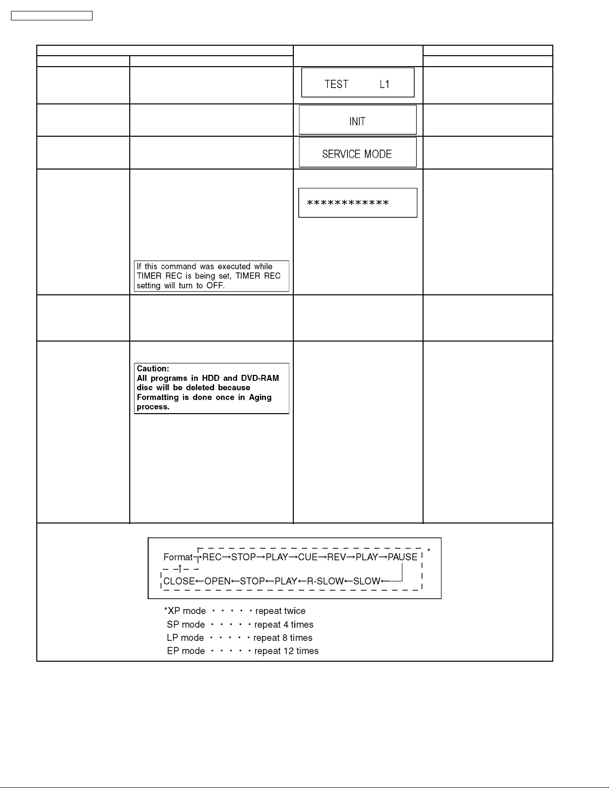
9.2. Special Modes Setting
Item FL display Key operation
Mode name Description Front Key
TEST Mode *All the main unit´s parameters (include tuner)
are initialized.
Rating password The audiovisual level setting password is
initialized to “Level 8”.
Service Mode Setting every kind of modes for servicing.
*Details are described in “9.3. Service
Mode”.
Forced disc eject Removing a disc that cannot be ejected.
The tray will open and unit will shift to P-off
mode.
*When Timer REC is ON or EXT-LINK is ON,
execute " Forced disc eject " after releasing
Timer REC or EXT- LINK.
*This command is not effective during "Child
lock" is ON.
While Demonstration Lock is being set, this
Forced disc eject function is not accepted.
The display before execution
leaves.
Press [STOP], [CH UP] and
[OPEN/CLOSE] keys
simultaneously for five seconds
when power is off.
Open the tray, and press [REC] and
[PLAY] simultaneously for 5
seconds.
When the power is off, press [CH
UP], [OPEN/CLOSE] and [REC]
keys simultaneously for 5 seconds.
When the power is off, press
[STOP] and [CH UP] keys
simultaneously for 5 seconds.
Forced power-off When the power button is not effective while
power is ON, turn off the power forcibly.
*When Timer REC is ON or EXT-LINK is ON,
execute “Forced Power-off” after releasing
Timer REC or EXT- LINK.
Aging Perform sequence of modes as * Aging
Description shown below continually.
Aging Contents (Example):
Display in P-off mode. Press [Power] key over than 10
seconds.
Display following the then mode. When the power is ON, press
[STOP], [POWER] and
[OPEN/CLOSE] simultaneously for
over 5 seconds and less than 10
seconds.
NOTE1:
If Unit has not turned into Aging
mode by operations shown above,
execute TEST MODE once and reexecute operation shown above.
(*All the main unit’s parameters
include tuner are initialized by TEST
mode.)
NOTE2:
If the unit has hung-up because of
pressing keys for over 10 seconds,
once turn off the power, and reexecute this command.
*When releasing Aging mode, press
[POWER] key.
14

Item FL display Key operation
Mode name Description Front Key
Demonstration
lock/unlock
Ejection of the disc is prohibited.
The lock setting is effective until unlocking the
tray and not released by “Main unit
*When lock the tray.
When the power is on, press
[STOP] and [POWER] keys
simultaneously for 5 seconds.
initialization” of service mode.
“LOCK” is displayed for 3 seconds.
*When unlock the tray.
When the power is on, press
[STOP] and [POWER] keys
simultaneously for 5 seconds.
“UNLOCK” is displayed for 3
seconds.
*When press OPEN/CLO SE key
while the tray being locked.
Press [OPEN/CLOSE] key while the
tray being locked.
Display “LOCK” for 3 seconds.
ATP Initialization ATP setting is initialized, and the unit turns off
automatically.
It is same with display in stop mode. When the power is on (E-E mode),
press [CH UP] and [CH DOWN]
simultaneously for 5 seconds.
DMR-ES10P / DMR-ES10PC
Progressive initialization The progressive setting is initialized to
Interlace.
The display before execution
leaves.
When the power is on (E-E mode),
press [STOP] and [PLAY]
simultaneously for 5 seconds.
15
DMR-ES10P / DMR-ES10PC
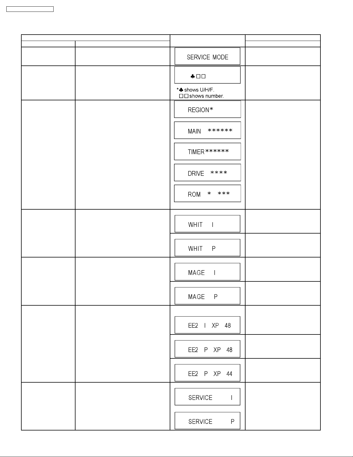
9.3. Service Modes
Service mode setting: While the power is off, press REC, CH UP and OPEN / CLOSE simultaneously for five seconds.
Item FL display Key operation
Mode name Description (Remote controller key)
Release Items Item of Service Mode executing is cancelled. Press [0] [0] or [Return] in service
mode.
Error Code Display Last Error Code of U/H/F held by Timer is
displayed on FL.
*Details are described in “9.1. Self-
Diagnosis Functions”.
ROM Version Display Region code, MAIN firm version, TIMER firm
version and DRIVE firmware versions are
displayed on FL for five seconds per each
version in order, but ROM version will be left
displayed.
White Picture Output White picture is output as component Output
from AV Decoder.
*White picture
(Saturation rate : 100%)
*It is enable to switch Interlace/Progressive by
“I/P switch: [1] [4]”
Press [0] [1] in service mode
Press [0] [2] in service mode
‘’*’’ are version displays.
*Initial mode is “Interlace”. Press [1] [1] in service mode.
Switch Interlace/Progressive Press [1] [4] in White Picture Output
mode.
*I/P are switched alternately.
Magenta Picture Output Magenta picture is output with Component
RTSC Return in XP
(A & V)
I/P Switch Switch Interlace and Progressive in EE mode.
Output from AV Decoder.
*Magenta picture
(Saturation rate: 100%)
*It is enable to switch Interlace/Progressive by
“I/P switch: [1] [4]”
L1 input signal is encoded (XP), decoded
(XP) and output decoded signal to external
without DISC recording and DISC playback.
*Initial setting is “Interlace”.
*This command is effective during executing
“White Picture Output”, “Magenta Picture
Output” and “RTSC Return in XP (A & V)”
modes.
*Initial mode is “Interlace”. Press [1] [2] in service mode.
Switch Interlace/Progressive Press [1] [4] in Magenta Picture
Initial mode: EE2/ Interlace/ XP/
Audio 48kHz
Switch Interlace/Progressive Press [1] [4] in RTSC Return XP
Audio 44.1 kHz/ 48 kHz Switch Press [2] [4] in RTSC Return XP
Initial mode is Interlace
Switch Interlace/Progressive
Output mode.
*I/P are switched alternately.
Press [1] [3] in service mode.
mode.
*I/P are switched alternately.
mode.
*48 kHz / 44.1 kHz are switched
alternately.
Press [1] [4] in I/P Switch mode.
*I/P are switched alternately.
16
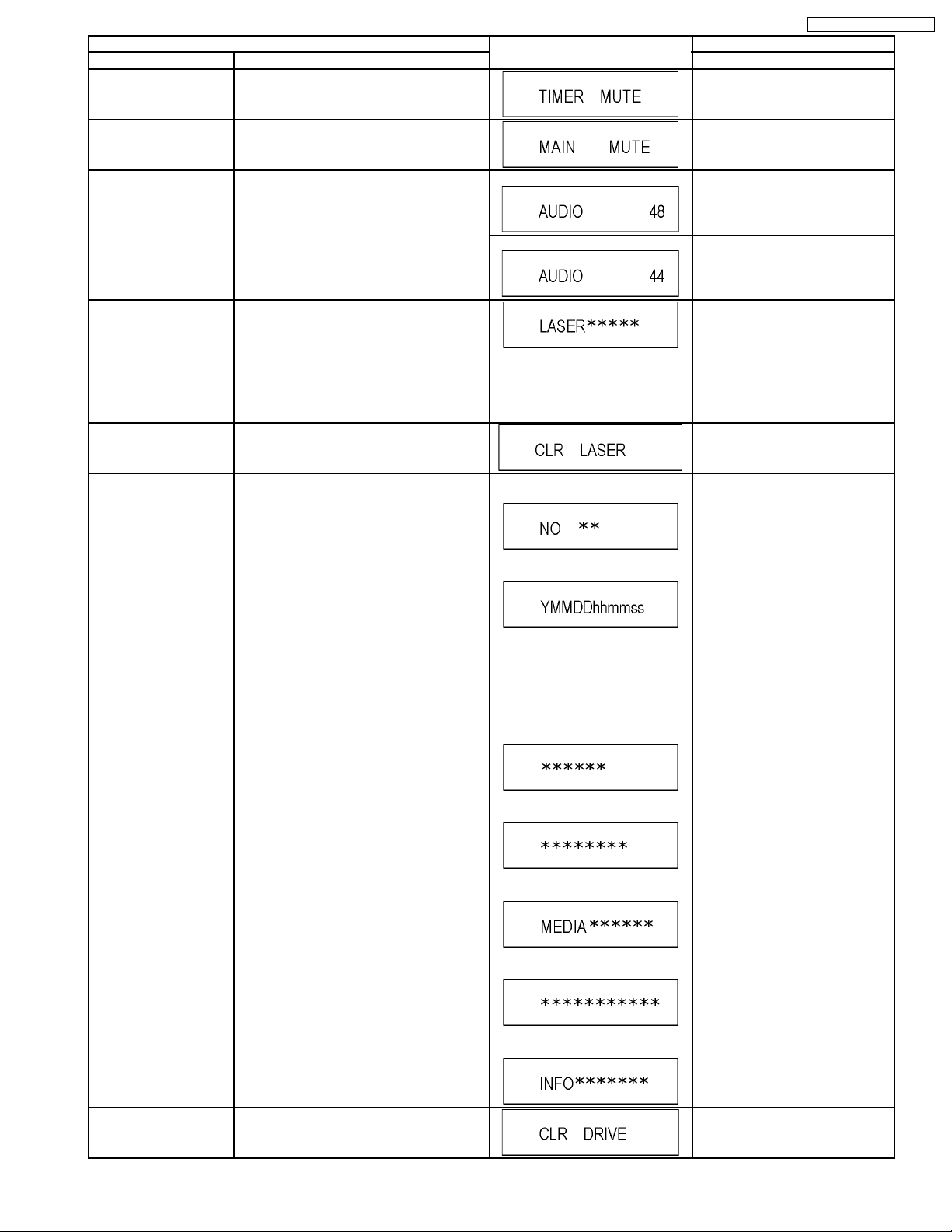
Item FL display Key operation
Mode name Description (Remote controller key)
Audio Mute (XTMUTE) Check whether mute is applied normally by
Press [2] [1] in service mode.
the timer microprocessor.
DMR-ES10P / DMR-ES10PC
Audio Mute (XDMUTE) Check whether mute is applied normally by
the Digital P.C.B..
Audio Pattern Output The audio pattern stored in the internal
memory is output
(Lch: 1kHz/-18dB)
(Rch: 400Hz/-18dB)
*Audio sound clock switching operation of
DAC can be confirmed by sub command [2]
[4].
Laser Used Time
Check laser used time (hours) of drive.
Indiction
Delete the Laser Used
Time
Laser used time stored in the memory of the
unit is deleted.
RAM Drive Last Error RAM Drive error code display.
*For details about the drive error code, refer
to the Service Manual for the specific RAM
Drive.
*Details are described in “8. Service
Explorer”.
Press [2] [2] in service mode.
Initial mode (Audio 48kHz) Press [2] [3] in service mode.
Audio 44.1kHz/48kHz switching Press [2] [4] in Audio Pattern Output
mode.
*48 kHz / 44.1 kHz are switched
alternately.
Press [4] [1] in service mode.
l(*****) is the used time display in
hour.
lLaser used time of DVD/ CD in
Playback/Recording mode is
counted.
Press [9] [5] in service mode.
1. Error Number is displayed for 5
seconds.
Press [4] [2] in service mode.
When “INFO******” is being
displayed, past 19 error histories
can be displayed by pressing [0] [1]
- [1] [9]
2. Time when the error has occurred
is displayed for 5 seconds.
Y: Year
MM: Month
DD: Day
hh: Hour
mm: Minute
ss: Second
3. Last Drive Error (1/2) is displayed
for 5 seconds.
4. Last Drive Error (2/2) is displayed
for 5 seconds.
5. Error occurring Disc type is
displayed for 5 seconds.
6. Disc Maker ID is displayed for 5
seconds.
7. Factor of Drive Error occurring is
left displayed
In case that the maker cannot be
identified, display is black out.
Delete the Last Drive
Error
Delete the Last Drive Error information stored
on the DVD RAM-Drive.
Press [9] [6] in service mode.
17
DMR-ES10P / DMR-ES10PC
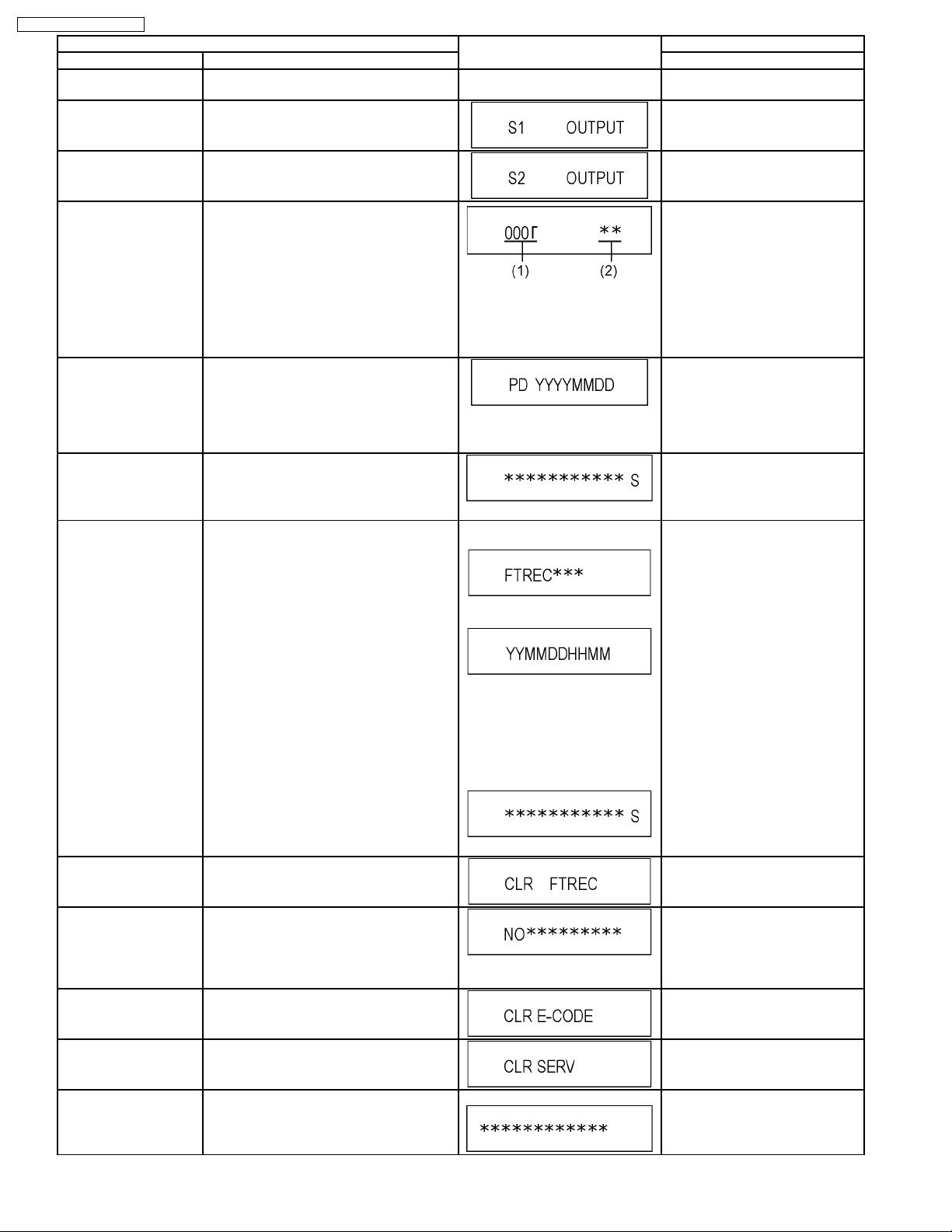
Item FL display Key operation
Mode name Description (Remote controller key)
Turn on all FL/LEDs All segments of FL and all LEDs are turned
on.
S1 signal output Forcibly superimpose the S1 signal (approx.
4.5V DC) on the EE chroma signal, and check
the output on the S terminal.
S2 signal output Forcibly superimpose the S2 signal (approx.
2V DC) on the EE chroma signal, and check
the output on the S terminal.
Front connection
inspection
Press all front keys and check the connection
between Main P.C.B. and Front key Switches.
Production Date Display Display the date when the unit was produced.
Display the accumlated
Display the accumulated unit´s working time.
working time
All segments are turned on. Press [5] [1] in service mode.
Press [5] [2] in service mode.
Press [5] [3] in service mode.
Press [5] [4] in service mode.
(1) Each time a key is pressed,
segment turned on increases one
by one.
(2) Total umber of keys that have
been pressed.
Press [6] [1] in service mode.
YYYY: Year
MM: Month
DD: Day
Press [6] [4] in service mode.
(Indicating unit: Second)
Display the Error History Display the Error History stored on the unit. Display reason of error for 5
seconds.
Display the time when the error has
occurred for 5 seconds..
YY: Year
MM: Month
DD: Day
HH: Hour
MM: Minute
Accumulated working time till
occuring of the error is left
displayed.
(Indicating unit: Second)
Delete the Error History Delete Error History information stored on the
unit.
Tray OPEN/CLO SE Test The RAM drive tray is opened and closed
repeatedly.
“*” is number of open/close cycle
times.
Error code initialization Initialization of the last error code held by
timer (Write in F00)
Press [6] [5] in service mode.
Then press [0] [1] ~ [1] [9], the past
19 error histories are displayed.
Press [9] [7] in service mode.
Press [9] [1] in service mode
*When releasing this mode, press
the [POWER] button of Remote
Controller more than 10 seconds.
Press [9] [8] in service mode.
Initialize Service Last Drive Error, Error history and Error
Press [9] [9] in service mode.
Codes stored on the unit are initialized to
factory setting.
Finishing service mode Release Service Mode. Display in STOP (E-E) mode. Press power button on the front
panel or Remote controller in
service mode.
18
DMR-ES10P / DMR-ES10PC
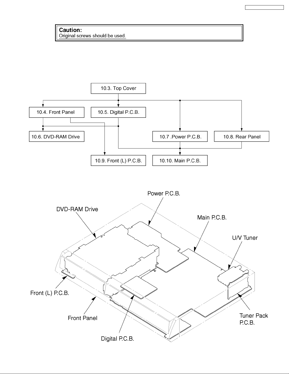
10 Assembling and Disassembling
10.1. Disassembly Flow Chart
The following chart is the procedure for disassembling the casing and inside parts for internal inspection when carrying out the
servicing.
To assemble the unit, reverse the steps shown in the chart below.
10.2. P.C.B. Positions
19
DMR-ES10P / DMR-ES10PC
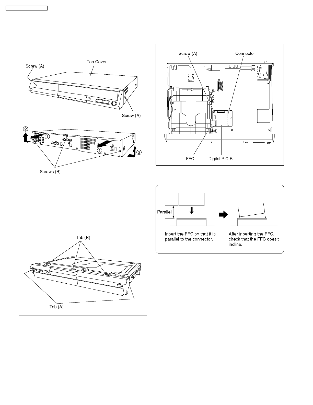
10.3. Top Cover
10.5. Digital P.C.B.
1. Remove the 2 screws (A) and 3 screws (B).
2. Slide Top Cover rearward and open the both ends at rear
side of the Top Cover a little and lift the Top Cover in the
direction of the arrows.
1. Remove FFC and a Screw (A).
2. Lift up Digital P.C.B. slightly so to disconnect Conne ctor to
remove Digital P.C.B.
CAUTION 1:
When replacing Digital P.C.B., pay attention as below.
10.4. Front Panel
1. Unlock 3 tabs (A) and 2 tabs (B) in this order to remove
Front Panel.
(The tab (A) and (B) should be unlocked at the same time,
respectively.)
CAUTION 2:
Be careful to do not touch surface of CSP ICs.
If you have touched surface of CSP IC, clean up with
alcohol and so on to prevent oxidation.
20
 Loading...