

Panasonic DMREH-80-VEB, DMREH-80-VEG Service manual
ORDER NO.DSD0510009CE
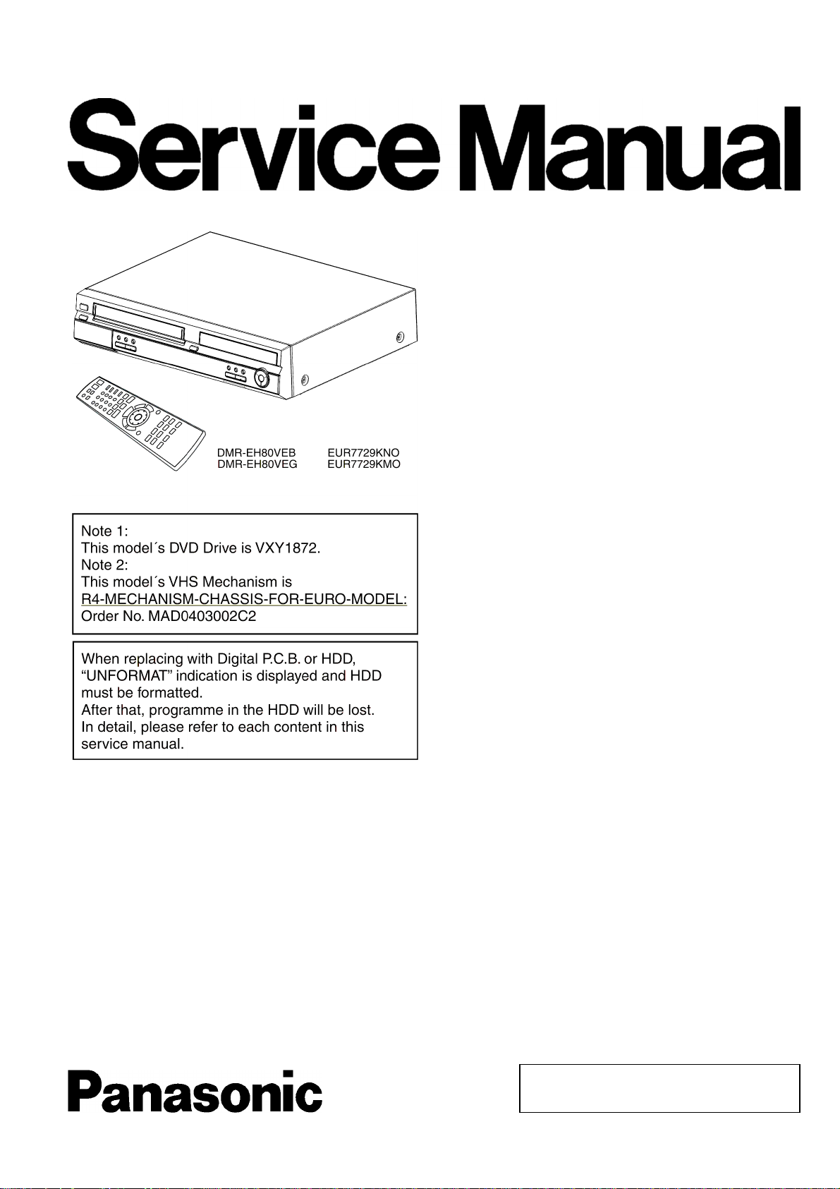
DVD Video Recorder
DMR-EH80VEG
DMR-EH80VEB
Vol. 1
Colour
(S).......................Silver Type
© 2005 Matsushita Electric Industrial CO., Ltd. All
rights reserved. Unauthorized copying and
distribution is a violation of law.
DMR-EH80VEG / DMR-EH80VEB
SPECIFICATIONS
Power supply: AC220-240 V, 50/60 Hz
Power consumption: 46W +/-1,3W
Dimensions and Mass: 430 (W)×380 (D)×89 (H) mm
Operating temperature range:+5 to +40°C
Operating humidity range: 35 to 80% RH (no condensation)
Pickup:
Laser power and Wave length:CLASS2/CLASS1 662nm / 795nm
No hazardous radiation is emitted with the safety protection
Laser performance: Class 3B / Class 3A (optical scan unit)
(NORSK) B : nm / 795nm
Laserstyrke Ingen farlig str
Video Recording signal: PAL
DVD Signal system: PAL625/50, PAL525/60
DVD Region number: Region No.2
Approximate Recording time (approximate):
DVD Video Recording and Playback format:
DVD-R: 12cm 4.7GB / 8cm 1.4GB
DVD-RW: 12cm 4.7GB
Only Playback format:
TV tuner system EB: 1x DVD / 1x VCR
TV tuner system EG: 1x DVD / 1x VCR
RF out system:
Video Recording system: 4 rotary heads (helical scanning system)
Video heads: 4 rotary video heads
Video input:
SD Card slot: Still picture (JPEG, TIFF)
Video output:
Ølgelengde 662
XP: 10 MBps 1h / 44h
SP: 5 MBps 2h / 89h
LP: 2,5 MBps 4h / 177h
EP: 1.7, 1.2 MBps 6h, 8h / 266h, 355h
Video: MPEG2 (Hybrid VBR) / Audio: Dolby Digital 2CH
DVD-RAM: 12cm 4.7GB / 9.4GB / 8cm 2.8GB
DVD+R: 12cm 4.7GB
DVD-Video, DVD-Audio, DVD+RW
CD-Audio (CD-DA), Video CD, S-Video CD (IEC62107)
CD-R/CD-RW (CD-DA, Video CD formatted discs)
MP3 (audio), JPG (picture)
Maximum number of tracks and groups: 999 tracks and 99 groups
DMR-EH80V EB UHF: CH21-CH68 (71 +/-3dBµ, 75Ω close)
DMR-EH80V EG without RF converter
EURO AV (AV1 / AV2) 21 pin connector (1.0Vp-p, 75W terminated)
VIDEO IN (AV3 front input) cinch connector (1.0Vp-p, 75W terminated)
S-VIDEO IN Y: 1Vp-p, C:0.3 Vp-p (PAL-Burst)
DV input IEEE1394 4pin PAL/NTSC
EURO AV (AV1 / AV2) 21 pin connector (1.0Vp-p, 75Ω terminated)
VHS / DVD 1x cinch (1.0Vp-p, 75Ω terminated)
DVD (only) component 3x cinch Progressive / Interlace
S-VIDEO Y (1.0Vp-p , 75Ω terminated)
Power Save mode: 5W+/-0,4W
(excluding protrusions) / 7kg
åling sendes ut
MESECAM (only EG)
NTSC (only from extern and DVD)
NTSC (playback on PAL TV)
DVD 4.7GB Disk / HDD 200GB
UHF: CH21-CH68
VHF (OIRT): CHR1-CHR12
VHF: CH E2-CH E12 A-H2
UHF: CH21-CH69
CATV: S01-S05 (S1-S3),
S1-S20(M1-U10), S21-S41
2 audio HIFI heads
1 audio head (normal audio)
SD Memory Card, MuliMediaCard
Format: FAT12, FAT16
B
(Y:1.0Vp-p, P
C PAL (0.3Vp-p, 75Ω terminated)
C NTSC (0.286 Vp-p, 75Ω terminated)
: 0.7Vp-p, PR: 0.7Vp-p)
DVD RGB video output:
RGB output level: 0.7 Vp-p (75O) +/-10%
Output terminal: AV (21pin)
Number of terminals: 1 system
Audio heads:
1 stationary head Mono
2 channels Hi-Fi Sound-Stereo
Audio input:
EURO AV (AV1 / AV2) 21 pin connector:
AUDIO IN (AV3 front input) cinch connector:
Audio output:
VHS / DVD, DVD only cinch connector:
EURO AV (AV1 / AV2) 21 pin connector:
DVD optical digital output audio out (PCM, Dolby Digital, DTS, MPEG)
Audio characteristics:
S/N ratio Normal: more than 43dB (SP)
Frequence responce Normal: 80Hz - 8kHz,
Total harmonic distortion: CD Audio: 0.0025%
Dynamic range:
VCR: more than 90dB
DVD (linear audio): more than 98dB
CD audio: more than 96dB
Videotape speed and Recording time (PAL / SECAM 240min. tape):
SP: 23.39mm/s, 240min.
LP: 11.695mm/s, 480min.
EP: 7.796mm/s, 720min.
FF / REW time: 60sec. (180min. tape)
Videotape speed and Recording time (NTSC 240min. tape):
SP: 33.35mm/s, 168min.
EP: 11.12mm/s, 505min.
Winding Speed (180min tape):
Note:
Specifications are subject to change without notice.
Mass and dimensions are approximate.
MPEG Layer-3 audio decoding technology licensed from Fraunhofer
IIS and Thomson multimedia.
This product incorporates copyright protection technology that is
protected by method claims of certain U.S. patents and other
intellectual property rights owned by Macrovision Corporation and
other rights owners. Use of this copyright protection technology must
be authorized by Macrovision Corporation, and is intended for home
and other limited viewing uses only unless otherwise autherwise
authorized by Macrovision Corporation. Reverse engineering or
disassembly is prohibited.
■
Built-in decoders
You can play discs with these symbols
-6dBV (500mV), more than 10kΩ
-6dBV (500mV), more than 10kΩ
-6dBV (500mV), less than 1kΩ
-6dBV (500mV), less than 1kΩ
Hi-Fi: 65dB,
DVD: 115dB
Hi-Fi: 20Hz - 20kHz
DVD: 4Hz - 22kHz (linear audio)
48kHz sampling
DVD: 4Hz - 44kHz (linear audio)
96kHz sampling
CD Audio: 4Hz - 20kHz
FF time approximate 60sec.
REW time approximate 43sec.
.
2

DMR-EH80VEG / DMR-EH80VEB
CONTENTS
Page Page
1 INTRODUCTION 5
2 SAFETY PRECAUTIONS
2.1. GENERAL GUIDELINES
3 PREVENTION OF ELECTROSTATIC DISCHARGE (ESD) TO
ELECTROSTATIC SENSITIVE (ES) DEVICES
4 PRECAUTION OF LASER DIODE
5 ABOUT LEAD FREE SOLDER (PbF)
6 PREVENTION OF STATIC ELECTRICITY DISCHARGE
6.1. GROUNDING FOR ELECTROSTATIC BREAKDOWN
PREVENTION
6.2. HANDLING PRECAUTIONS FOR OPTICAL PICK-UP
UNIT
7 GENERAL DESCRIPTION
8 NEW FEATURES
8.1. QUICK START FUNCTION (REC)
9 (DVD) TAKING OUT THE DISC FROM RAM-DRIVE UNIT WHEN
THE DISC CANNOT BE EJECTED BY BUTTON
9.1. (DVD) FORCIBLE DISC EJECT
9.2. (DVD) WHEN THE FORCIBLE DISC EJECT CAN NOT
BE DONE.
10 (VHS) REMOVING OF CASSETTE TAPE
10.1. (VHS) REMOVAL BY COMPULSORY UNLOADING.
10.2. (VHS) REMOVAL BY MANUAL OPERATION.
10.3. (VHS) TAKE OUT CASSETTE TAPE MANUALLY AFTER
REMOVING THE MECHANNISM
11 (DVD) SERVICE EXPLORE R
12 (DVD) SELF-DIAGNOSIS AND SPECIAL MODE SETTING
12.1. (DVD) SELF-DIAGNOSIS FUNCTIONS
12.2. (DVD) SPECIAL MODES SETTING
12.3. (DVD) SERVICE MODES
13 (VHS) SELF-DIAGNOSIS AND SPECIAL MODE SETTING
13.1. (VHS) SPECIAL MODES SETTING
13.2. (VHS) SERVICE MODES
13.3. (VHS) SELF-DIAGNOSIS FUNCTIONS
14 ASSEMBLING AND DISASSEM BLING
14.1. DISASSEMBLY FLOW CHART
14.2. P.C.B. POSITIONS
14.3. CAUTION WHILE INSERTING CASSETTE TAPE WHEN
DISASSEMBLING THE UNIT
14.4. TOP CASE
14.5. FRONT PANEL
14.6. FRONT JACK P.C.B. & FL DRIVE P.C.B.
14.7. POWER P.C.B.
14.8. REAR PANEL & FAN MOTOR
14.9. VCR MECHANISM UNIT
14.10. MAIN P.C.B.
14.11. TUNER / CONVERTER /DECODER
14.12. DVD-RAM DRIVE
14.13. DIGITAL P.C.B.
14.14. HARD DISK DRIVE
14.15. SD CARD P.C.B.
10
10
11
11
11
12
12
12
13
14
17
17
19
21
27
27
27
28
30
30
30
30
31
31
32
32
33
34
35
35
35
36
37
38
14.16. DIGITAL I/F P.C.B.
5
15 SERVICE FIXTURE AND TOOLS
16 SERVICE POSITIONS
5
16.1. CHECKING AND REPAIRING OF POWER P.C.B.
6
7
7
8
8
8
9
16.2. CHECKING AND REPAIRING OF DIGITAL I/F P.C.B.
16.3. CHECKING AND REPAIRING OF MAIN P.C.B.
16.4. CHECKING AND REPAIRING OF DVD-RAM DRIVE
16.5. CHECKING AND REPAIRING OF HARD DISK DRIVE
16.6. CHECKING AND REPAIRING OF SD CARD P.C.B.
17 (DVD) CAUTION AFTER REPLACING PARTS
17.1. (DVD) AFTER REPLACING THE RAM DRIVE
17.2. (DVD) AFTER REPLACING THE TIMER
MICROPROCESSOR
17.3. (DVD) AFTER REPLACING EEPROM (IC37502)
18 (VHS) CAUTION AFTER REPLACING PARTS
18.1. ADJUSTMENT PROCEDURES AFTER REPLACING DD
CYLINDER, VHS MICROPOCESSOR OR MAIN P.C.B
18.2. (VHS) X-VALUE & LINEARITY (P2 AND P3 POSTS)
ADJUSTMENT
18.3. (VHS) CAUTION AFTER REPLACING VHS
MICROPROCESSOR (IC6001)
19 (DVD) STANDARD INSPECTIO N SPECIFICATIONS AFTER
MAKING REPAIRS
20 VOLTAGE AND WAVEFORM CHART
20.1. WAVEFORM CHART
21 ABBREVIATIONS
21.1. DVD
21.2. VHS
22 INTERCON NECTION DIAGRAM
23 BLOCK DIAGRAM
23.1. POWER SUPPLY BLOCK DIAGRAM
23.2. DIGITAL I/F REGULATOR BLOCK DIAGRAM
23.3. SYSTEM CONTROL, SERVO & TIMER BLOCK
DIAGRAM
23.4. AUDIO BLOCK DIAGRAM
23.5. VIDEO BLOCK DIAGRAM
23.6. DIGITAL I/F P.C.B. BLOCK DIAGRAM
24 SCHEMATIC DIAGRAM
24.1. POWER SUPPLY
24.2. DVD OUTPUT
24.3. INTERFACE
24.4. IO / TUNER
24.5. SYSCON / SERVO / TIMER MAIN
24.6. VHS AUDIO
24.7. VIDEO
24.8. NICAM DECODER
24.9. FRONT JACK
24.10. FL DRIVE
24.11. SD CARD / DV IN
25 PRINTED CIRCUIT BOARD
25.1. POWER P.C.B. (COMPONENT SIDE)
38
39
40
40
41
43
44
45
46
47
47
47
47
48
48
49
50
51
52
58
59
59
61
65
67
67
68
69
70
71
73
75
75
77
78
79
80
81
82
83
84
85
86
87
87
3

DMR-EH80VEG / DMR-EH80VEB
25.2. POWER P.C.B. (SOLDER SIDE) 88
25.3. MAIN P.C.B. (COMPONENT SIDE)
25.4. MAIN P.C.B. (SOLDER SIDE)
25.5. DIGITAL I/F P.C.B. (COMPONENT SIDE)
25.6. DIGITAL I/F P.C.B. (SOLDER SIDE)
25.7. NICAM DECODER P.C.B. (VEP07A51A / VEP07A51B)
25.8. NICAM DECODER P.C.B. (VEP07A51F)
25.9. FRONT JACK P.C.B.
25.10. FL DRIVE P.C.B.
25.11. SD CARD P.C.B.
26 EXPLODED VIEWS
26.1. MECHANISM & CASING PARTS
26.2. FRONT PANEL PARTS
26.3. VHS MECHANISM PARTS
26.4. PACKING & ACCESSORIES
27 REPLACEMNET PARTS LIST
89
90
91
92
93
94
95
96
97
99
99
100
101
102
103
27.1. VHS MECHANISM PARTS
27.2. MECHANISM & CASING PARTS
27.3. PRINTED CIRCUIT BOARDSINCLUDED IN MAIN PCB
27.4. PACKING & ACCESSORIES PARTS
27.5. ELECTRICAL PARTS
27.6. SERVICE FIXTURE AND TOOLS
28 DIAGRAMS FOR PRINTING A4 SIZE
28.1. BLOCK DIAGRAM FOR PRINTING A4 SIZE
28.2. SCHEMATIC DIAGRAMM FOR PRINTING A4 SIZE
28.3. POWER P.C.B. FOR PRINTING A4 SIZE
28.4. MAIN P.C.B. (COMPONENT SIDE) FOR PRINTING A4
SIZE
28.5. MAIN P.C.B. (SOLDER SIDE) FOR PRINTING A4 SIZE
28.6. OTHER P.C.B.’s FOR PRINTING A4 SIZE
103
103
104
104
105
116
117
117
133
157
161
163
165
4
1 INTRODUCTION
This service manual contains technical information which will
allow service personnel to understand and service these
models.
Please place orders using the parts list and not the drawing
reference numbers.
1. This service manual does not contain the following
information, because of the impossibility of servicing at
component level.
•
• Schematic Diagram, Block Diagram and P.C.B. layout
• •
of Digital P.C.B.
•
• Parts List for individual parts of Digital P.C.B.
• •
•
• Exploded View and Parts List for individual parts of RAM
• •
drive.
2. The following categories are recycling module part. Please
send them to Central Repair Center.
•
• Digital P.C.B.:
• •
DMR-EH80VEB: RFKBEH80VEB
DMR-EH80VEG: VEP79108E
•
• RAM Drive: RFKNVXY1872
• •
3. If the circuit is changed or modified, this information will be
followed by supplement service manual to be filed with
original service manual.
4. Adjustment procedures, Disassembly Procedures and
Assembly Procedures for VCR Mechanism Chassis are
separate volume from this service manual. Please refer to
the service manual for R4 Mechanism Chassis for EURO
model (MAD0403002C2).
2 SAFETY PRECAUTIONS
2.1. GENERAL GUIDELINES
1. Be careful during removing metal parts, sharp edges.
2. When servicing, observe the original lead dress. If a short
circuit is found, replace all parts which have been
overheated or damaged by the short circuit.
3. After servicing, see to it that all the protective devices such
as insulation barriers, insulation papers shields are properly
installed.
4. After servicing, make the following leakage current checks
to prevent the customer from being exposed to shock
hazards.
DMR-EH80VEG / DMR-EH80VEB
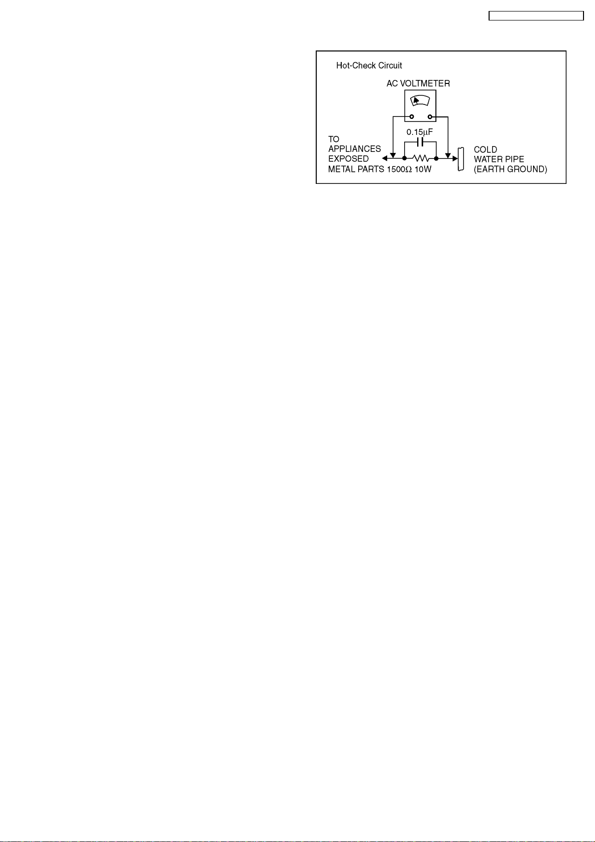
Figure 1
2.1.2. LEAKAGE CURRENT HOT CHECK
1. Plug the AC cord directly into the AC outlet. Do not use an
isolation transformer for this check.
2. Connect a 1.5kΩ, 10 watts resistor, in parallel with a 0.15µF
capacitors, between each exposed metallic part on the set
and a good earth ground such as a water pipe, as shown in
Figure 1.
3. Use an AC voltmeter, with 1000 ohms/volt or more
sensitivity, to measure the potential across the resistor.
4. Check each exposed metallic part, and measure the
voltage at each point.
5. Reverse the AC plug in theAC outlet and repeat each ofthe
above measurements.
6. The potential at any point should not exceed 0.75 volts
RMS. A leakage current tester (Simpson Model 229 or
equivalent) may be used to make the hot checks, leakage
current must not exceed 1/2 milliampere. In case a
measurement is outside of the limits specified, there is a
possibility of a shock hazard, and the equipment should be
repaired and rechecked before it is returned to the
customer.
2.1.1. LEAKAGE CURRENT COLD
CHECK
1. Unplug the AC cord and connect a jumper between the two
prongs on the plug.
2. Measure the resistance value, with an ohmmeter, between
the jumpered AC plug and each exposed metallic cabinet
part on the equipment such as screw heads, connectors,
control shafts, etc. When the exposed metallic part has a
return path to the chassis, the reading should be between
1MΩ and 5.2MΩ.
When the exposed metal does not have a return path to
the chassis, the reading must be infinity.
5
DMR-EH80VEG / DMR-EH80VEB
3 PREVENTION OF ELECTROSTATIC DISCHARGE (ESD)
TO ELECTROSTATIC SENSITIVE (ES) DEVICES
Some semiconductor (solid state) devices can be damaged
easily by static electricity. Such components commonly are
called Electrostatic Sensitive (ES) Devices. Examples of typical
ES devices are integrated circuits and some field-effect
transistor-sand semiconductor "chip" components. The
following techniques should be used to help reduce the
incidence of component damage caused by electrostatic
discharge (ESD).
1. Immediately before handling any semiconductor
component or semiconductor-equipped assembly, drain off
any ESD on your body by touching a known earth ground.
Alternatively, obtain and wear a commercially available
discharging ESD wrist strap, which should be removed for
potential shock reasons prior to applying power to the unit
under test.
2. After removing an electrical assembly equipped with ES
devices, place the assembly on a conductive surface such
as aluminum foil, to prevent electrostatic charge buildup or
exposure of the assembly.
3. Use only a grounded-tip soldering iron to solder
or unsolder ES devices.
4. Use only an anti-static solder removal device.
Some solder removal devices not classified
as "anti-static (ESD protected)" can generate electrical
charge sufficient to damage ES devices.
5. Do not use freon-propelled chemicals. These can generate
electrical charges sufficient to damage ES devices.
6. Do not remove a replacement ES device from its protective
package until immediately before you are ready to install it.
(Most replacement ES devices are packaged with leads
electrically shorted together by conductive foam, aluminum
foil or comparable conductive material).
7. Immediately before removing the protective material from
the leads of a replacement ES device, touch the protective
material to the chassis or circuit assembly into which the
device will be installed.
Caution
Be sure no power is applied to the chassis or circuit, and
observe all other safety precautions.
8. Minimize bodily motions when handling unpacked
replacement ES devices. (Otherwise harmless motion such
as the brushing together of your clothes fabric or the lifting
of your foot from a carpeted floor can generate static
electricity sufficient to damage an ES device).
6
DMR-EH80VEG / DMR-EH80VEB
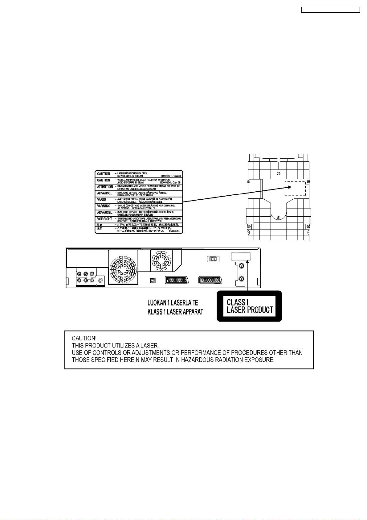
4 PRECAUTION OF LASER DIODE
CAUTION: ACHTUNG:
This product utilizes a laser diode with the unit turned “on”,
invisible laser radiation is emitted from the pickup lens.
Wave length: 662 nm/795 nm
Maximum output radiation power from pickup: 100µ W/VDE.
Laser radiation from the pickup lens is safety level, but be sure
the followings:
1. Do not disassemble the optical pickup unit, since radiation
from exposed laser diode is dangerous.
2. Do not adjust the variable resistor on the pickup unit.
It was already adjusted.
3. Do not look at the focus lens using optical instruments. 3. Nicht in die Fokussierlinse blicken.
4. Recommend not to look at pickup lens for a long time. 4. Auch nicht mit optischen Instrumenten in die Fokussierlinse blicken.
Dieses Produkt enthält eine Laserdiode.
Im eingeschalteten Zustand wird unsichtbare Laserstrahlung von der
Lasereinheit ausgestrahlt.
Wellenlänge: 662 nm/795 nm
Maximale Strahlungsleistung der Lasereinheit: 100µ W/VDE.
Die Strahlung der eingeschalteten Lasereinheit ist ungefährlich, wenn
folgende Punkte beachtet werden:
1. Die Lasereinheit nicht zerlegen, da die Strahlung an der freigelegten
Laserdiode gefährlich ist.
2. Den werksseitig justierten Einstellregler der Lasereinheit nicht
verstellen.
5 ABOUT LEAD FREE SOLDER (PbF)
This model uses lead free solder (PbF). For repair use only
lead free handsolder.
Caution:
Pb free solder has a higher melting point than standard
solder; Typically the melting point is 50 - 70°F (30 - 40°C)
higher. Please use a high temperature soldering iron. In
case of the soldering iron with temperature control, please
set it to 700 +/-20°F (370 +/-10°C). Pb free solder will tend
to splash when heated too high (about 1100°F/ 600°C).
When soldering or unsoldering, please completely remove
all of the solder on the pins or solder area and be sure to
heat the soldering points with the Pb free solder until it
melts enough.
7
DMR-EH80VEG / DMR-EH80VEB
6 PREVENTION OF STATIC ELECTRICITY DISCHARGE
The laser diode in the traverse unit (optical pickup) may brake
down due to static electricity of clothes or human body. Use
due caution to electrostatic breakdown when servicing and
handling the laser diode.
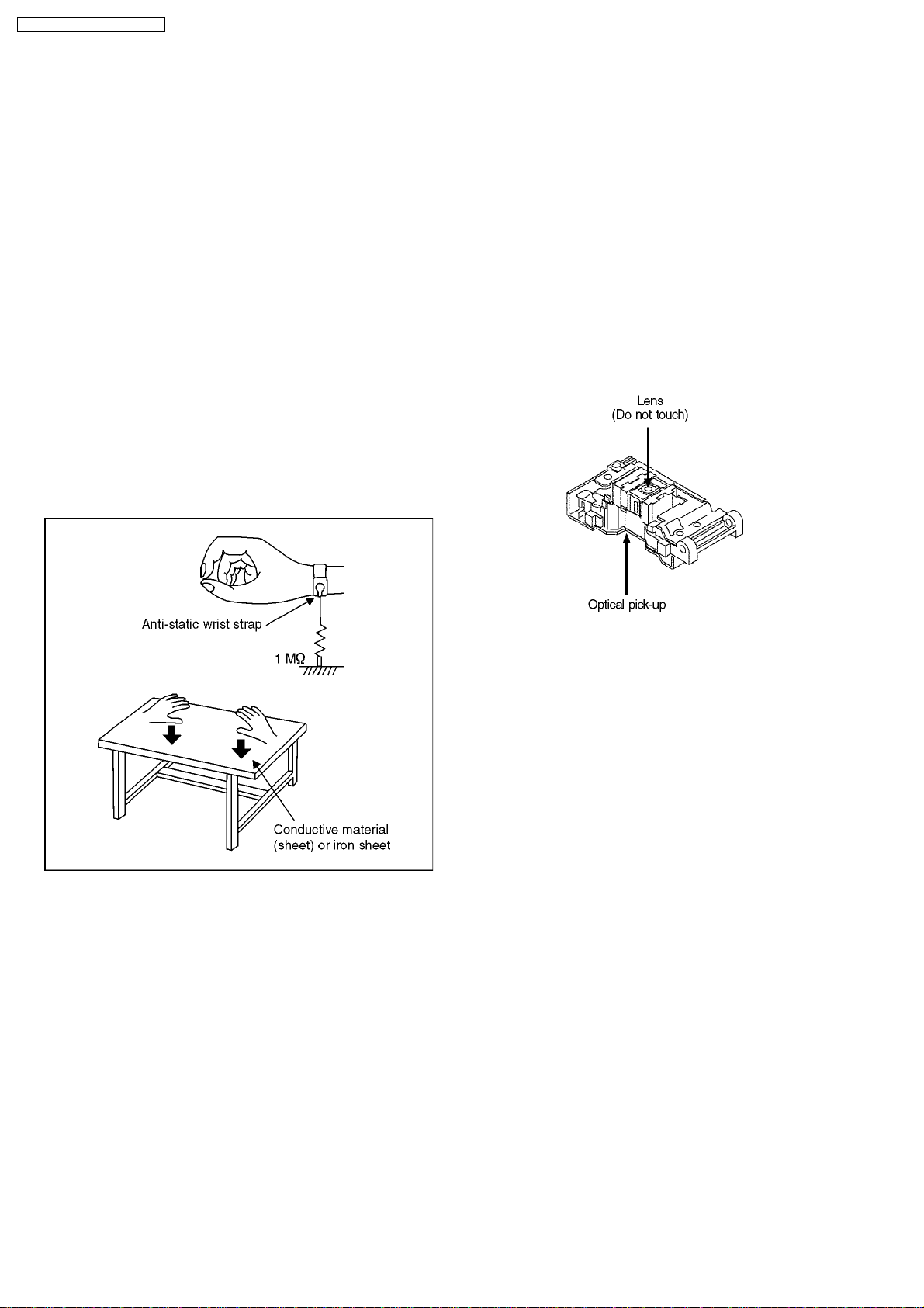
6.1. GROUNDING FOR
ELECTROSTATIC
BREAKDOWN PREVENTION
Some devices are using the optical pickup (laser diode) and the
optical pickup will be damaged by static electricity in the
working environment. Proceed servicing works under the
working environment where grounding works is completed.
6.1.1. WORKTABLE GROUNDING
1. Put a conductive material (sheet) or iron sheet on the area
where the optical pickup is placed, and ground the sheet.
6.1.2. HUMAN BODY GROUNDING
1. Use the anti-static wrist strap to discharge the static
electricity form your body.
6.2. HANDLING PRECAUTIONS
FOR OPTICAL PICK-UP UNIT
The laser diode in the optical pick-up unit may break down due
to potential difference caused by static electricity of clothes or
human body.
So be careful of electrostatic breakdown during repair of the
optical pick-up unit.
6.2.1. HANDLING OF OPTICAL PICK-UP
UNIT
1. The optical pick-up unit has high precision extremely
sensitive structure. Be careful not to apply excessive shock.
6.1.3. HANDLING OF OPTICAL PICKUP
1. To keep the good quality of the optical pickup maintenance
parts during transportation and before installation, the both
ends of the laser diode are short-circuit. After replacing the
parts with new ones, remove the short circuit according to
the correct procedure.
2. Do not use a tester to check the laser diode for the optical
pickup. Failure to do so will damage the laser diode due to
the power supply in the tester.
8
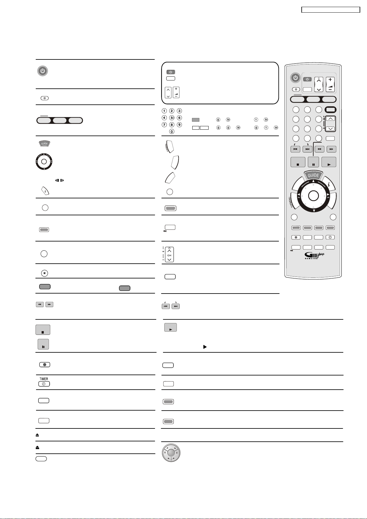
7 GENERAL DESCRIPTION
VCR, DVD and HD Controls
DVD/VHS
Stand-by/on switch
Press to switch the unit from on to stand-by mode
or vice versa. In stand-by mode, the unit is still consuming
a small amount of power.
DIRECT TV REC
Direct TV record to DVD or HDD.
Buttons to switch between VHS, HDD, DVD and SD.
VHS
HDD
DVD
Press the corresponding button
to operate the desired element.
The unit is switched on from electrical standby mode.
Launch the GUIDE Plus+ system.
Smart Wheel: Press up, down, left or right
to select the Function in the menu.
ENTER
Rotate the wheel to select the parameter.
ENTER: Select or save a setting.
Still picture or time loop playback.
Display the programme information from
the GUIDE Plus+ system.
SUB MENU
Launch DVD sub-menus.
S
Time and detail information appears
STATUS
on the screen.
GUIDE Plus+ menu: GREEN - Forward 24 hours.
INPUT SELECT
Switch button of the AV input between AV1, AV2
and AV3 (front) / TP (DVD) and DC (VHS), AV4, DV.
CANCEL/RESET
Cancel a function.
VHS - Reset the tape counter.
ShowView
ShowView menu
VIDEO Plus+
EB Model
TV
AV
CH
R
O
T
T
A
C
G
I
E
V
R
I
A
D
N
C
E
H
C
/
G
O
R
P
RETURN
DISPLAY
TIME SLIP
JET REW
TRACKING/V-LOCK
AUDIO
Turn the television set on and off.
Select the AV input on the television set.
CH: Select the channel on the television set.
VOLUME
VOLUME: Volume control of the television set.
Number buttons - direct input
VCD
5: + 15: +
MP3
JPEG
5: + + 15: + +
DIRECT NAVIGATOR TITLE VIEW
TOPMENU: Main menu of DVD video.
F
U
N
C
T
I
O
FUNCTION selection menu.
N
S
K
TIMER RECORDING menu.
Exit a menu.
Launch the disc menu.
GUIDE Plus+ menu: RED - Back 24 hours.
TIME SLIP: DVD - Select the timeframe
to be skipped.
JET REW: VHS - Fast rewind to the
beginning of the cassette.
CH: Channel select button.
TRACKING/V.LOCK + / -
VHS -
Optimisation of the playback picture
DVD - Depending on the disc, select the audio
channel and or the sound track.
VHS - Press several times to select
sound playback mode.
DMR-EH80VEG / DMR-EH80VEB
DVD/VHS
TV
VOLUME
AV
2
5
8
0
K
C
E
H
STATUS
REC MODE
AUDIO
CH
HDD
3
TRACKING/V-LOCK/PAGE
6
9
INPUT SELECT
REW
PAUSE
ENTER
CREATE
CHAPTER
EXT LINK
DUBBING
DVD
SD
CH
ShowView
SLOW/
SEARCH
PLAY
RETURN
HDD/DVD
ERASE
TIMER
MANUAL SKIP
FF
F
U
N
C
T
I
O
N
S
DIRECT TV REC
VHS
1
4
7
CANCEL/RESET
*
SKIP/INDEX
STOP
C
/
G
O
R
P
R
O
T
T
A
C
G
I
E
V
R
I
A
D
N
SUB MENU
S
DISPLAY
REC
TIME SLIP
JET REW
.
Panasonic
DVD/TV
EUR7729KM0
SLOW/
FF
REW
SEARCH
STOP
PAU SE
REC
EXT LINK
DUBBING
EJECT
OPEN/CLOSE
DRIVE SELECT
SLOW/SEARCH:
REW/FF:
DVD - Search or slow motion playback.
VHS - Fast forward or rewind from stop mode.
Forward or reverse scene search during playback mode.
Stops recording, replay or forward .
/reverse action
Press and hold more than 3 seconds
to remove cassette.
Pause a recording or playback.
Start the recording.
Switch timer on and off.
Record with external recording control.
DUBBING menu
Front Panel Button: Remove cassette
Front Panel Button: Open and close the disc tray
Front Panel Button:
Seclection HDD, DVD, SD
SKIP/INDEX
PLAY
REC MODE
MANUAL SKIP
HDD/DVD
ERASE
CREATE
CHAPTER
VHS/DVD
EXT LINK
HDD
DUBBING
VHS
DVD
SKIP: DVD - Skip chapters, titles, or pictures.
INDEX: VHS - Search for the beginning of a recording.
Starts playback.
PLAY/ x1.3
HDD / RAM - You can increase the playback speed.
Hold PLAY during playback.
Record mode button DVD - XP, SP, LP, EP
Record mode button VHS - SP, LP, EP
DVD - Jumps forward 30 seconds.
Erase a title or a chapter.
GUIDE Plus+ menu: BLUE - Programme Type selection.
Split the recording into chapters.
Front Panel Button: Recording with external recording control
Front Panel Button: One Touch Dubbing (HD, DVD, TAPE)
9
DMR-EH80VEG / DMR-EH80VEB
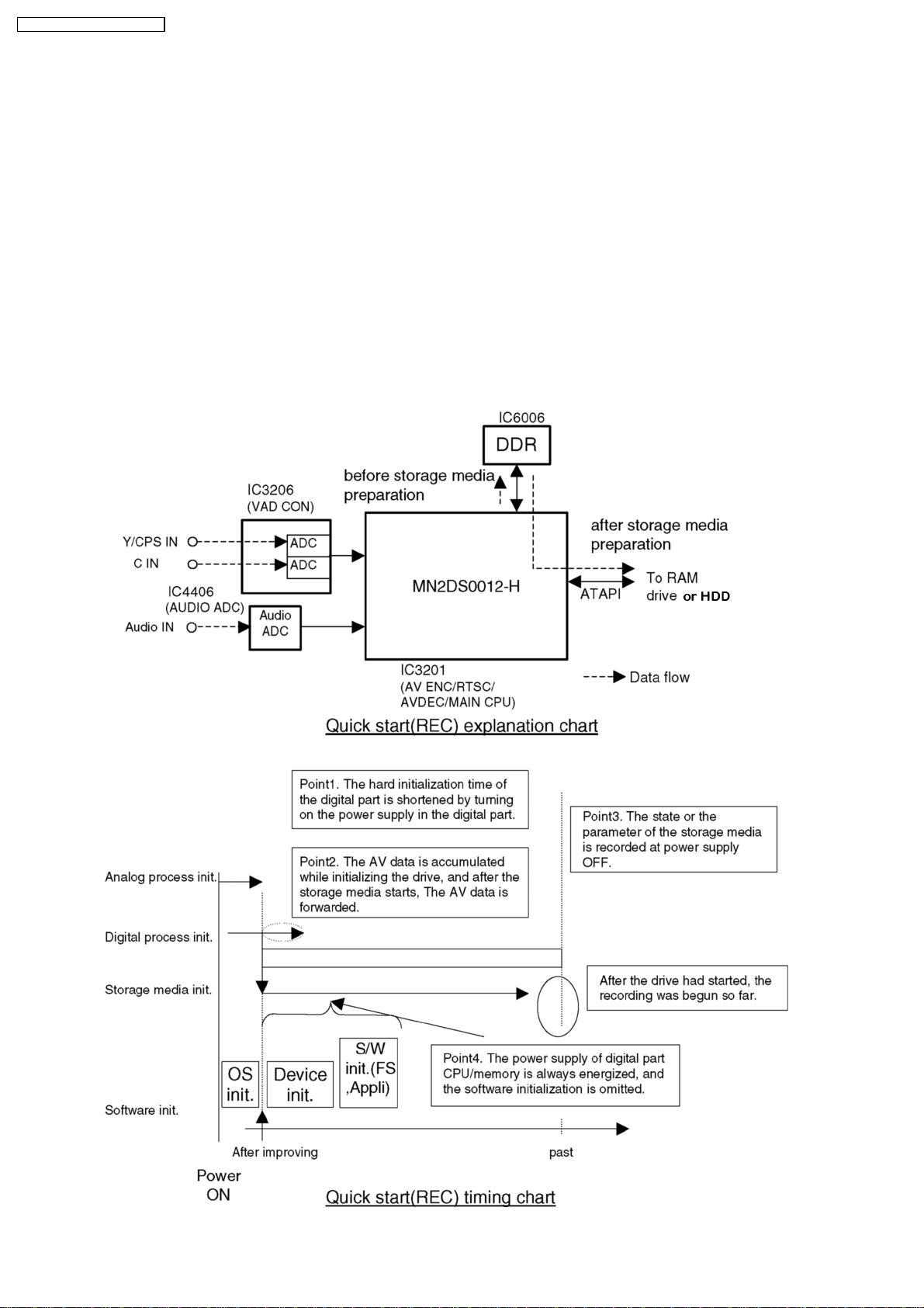
8 NEW FEATURES
8.1. QUICK START FUNCTION (REC)
(Note: Descriptions concerning HDD is applied only to models with HDD.)
1. General
A few seconds after tuning on the unit, you can start recording to DVD-RAM, HDD.
You can switch the operation of this function (ON/OFF) on the menu screen.
2. Quick start (REC) principle
In the power-off at Quick start, only power supplies for video IC, tuner and storage media are cut off.
2.1. When the REC button is pushed a few second after the power button is pushed, Audio and Video data are stored
in DDR SDRAM before a storage media (DVD-RAM or HDD) preparation.
*Preparation time → DVD-RAM: About 8 seconds
2.2. After a storage media DVD-RAM or HDD preparation, Audio and Video data are transfered from DDR SDRAM to
the storage media.
10
DMR-EH80VEG / DMR-EH80VEB
9 (DVD) TAKING OUT THE DISC FROM RAM-DRIVE UNIT
WHEN THE DISC CANNOT BE EJECTED BY BUTTON
9.1. (DVD) FORCIBLE DISC EJECT
9.1.1. (DVD) WHEN THE POWER CAN BE
TURNED OFF.
1. Turn off the power and press [(DVD) STOP], [(DVD) CH
UP] keys on the front panel simultaneously for 5 seconds.
9.1.2. (DVD) WHEN THE POWER CAN
NOT BE TURNED OFF.
1. Press [POWER] key on the front panel for over 10 seconds
to turn off the power forcibly
and press [(DVD) STOP] [(DVD) CH UP] keys on the front
panel simultaneously for 5 seconds.
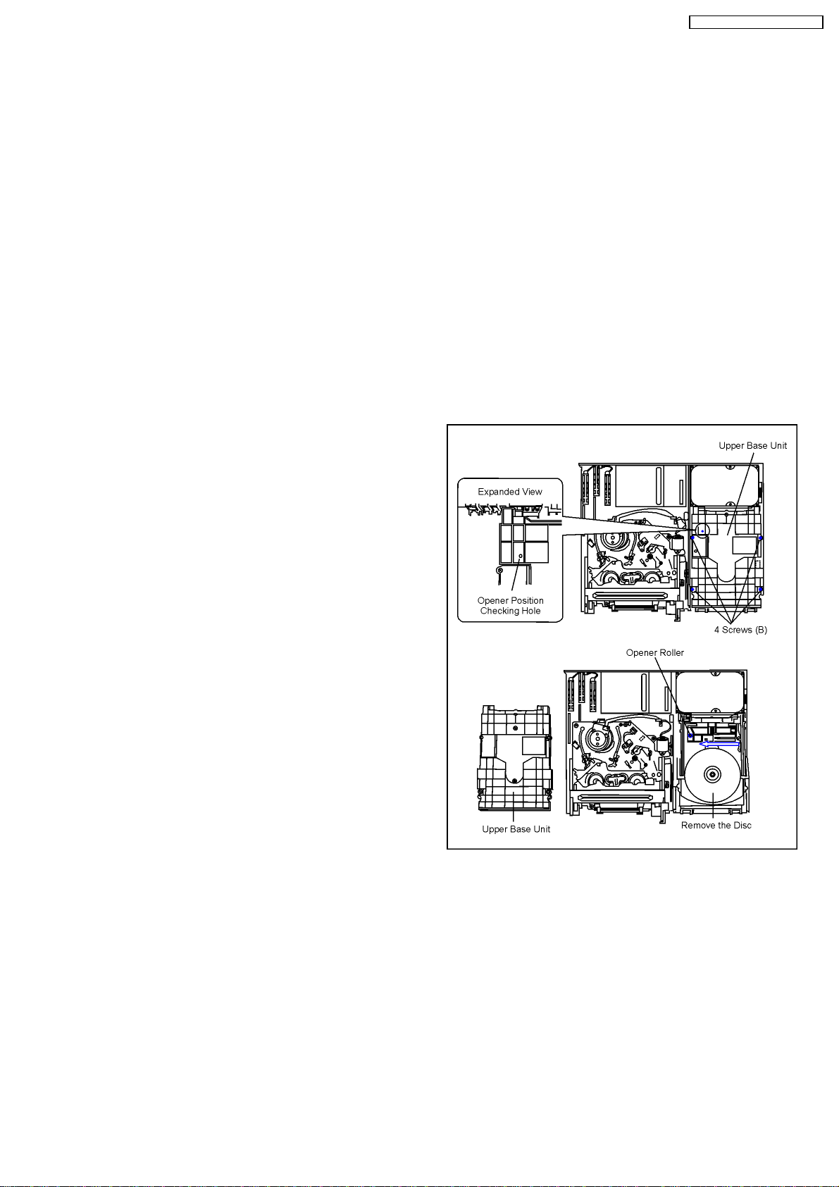
9.2. (DVD) WHEN THE FORCIBLE
DISC EJECT CAN NOT BE
DONE.
1. Turn off the power and pull out AC cord.
2. Remove the Top Case.
3. Remove the Front Panel.
4. Remove 4 screws (B) and Upper Base Unit from DVD-RAM
Drive.
5. Take out the disc and put the Opener Roller on fullyposition
for direction of Arrow.
6. Put the Upper Base Unit so that the Opener Roller is
inserted into the groove.
7. Check center of Opener Roller is seen through the Opener
position Checking Hole, and tighten 4 screws (B).
11
DMR-EH80VEG / DMR-EH80VEB
10 (VHS) REMOVIN G OF
CASSETTE TAPE
When the cassette tape could not be removed after an
electrical malfunction, there are 2 ways to remove a cassette
tape.
10.1. (VHS) REMOVAL BY
COMPULSORY UNLOADING.
If Service Mode can be activated when the power can not be
turned on, this operation is able.
1. Press [FF] and [EJECT] button simultaneously for more
than 3 seconds and set the Service Mode to 7.
2. Press [STOP] button in order to unload the mechanism.
(Pay attention to tape slack)
Service Mode Display:
7 ** ** (STOP) → 7 0L ** (EJECT)
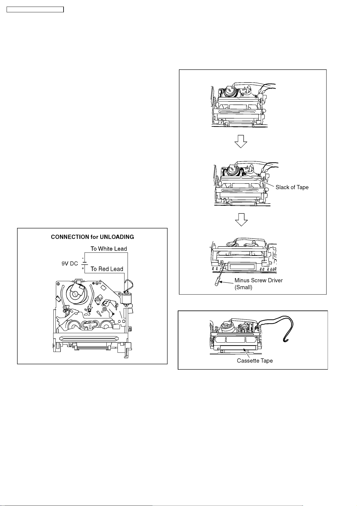
10.2. (VHS) REMOVAL BY MANUAL
OPERATION.
1. Disconnect the AC plug, and remove the Top Panel and the
Front Panel by referring to the Disassembly Procedures.
2. Connect a batterie (9V spec.) to the Loading Motor in series
for supplying 9V to rotate the Loading Motor.
3. Stop unloading just before unloading willbe completed. The
tape becomes slack.
4. Rotate the S-Reel by a small minus screwdriver to remove
the slack tape.
5. Then unload again to remove the cassette tape.
12
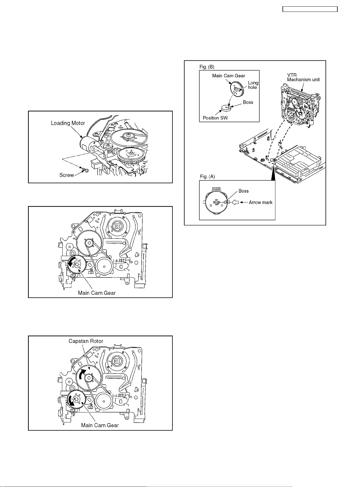
10.3. (VHS) TAKE OUT CASSETTE
TAPE MANUALLY AFTER
REMOVING THE
MECHANNISM
1. Disconnect the AC plug, and remove the Top Panel, Front
Panel and the Mechanism by referring assembling and
disassembling description.
2. Remove the Screw and remove the Loading Motor.
DMR-EH80VEG / DMR-EH80VEB
6. Attach Loading Motor and tighten the screw.
7. Set the Position Switch to EJECT POSITION certainly and
attach the mechanism to chassis.
3. Rotate the Main Cam Gear counter-clockwise until just
before the unloading will be completed.
4. Rotate the Capstan Motor clockwise to remove the slack
tape.
5. Rotate the Main Cam Gear counter-clockwise again to
remove the cassette-tape.
13
DMR-EH80VEG / DMR-EH80VEB
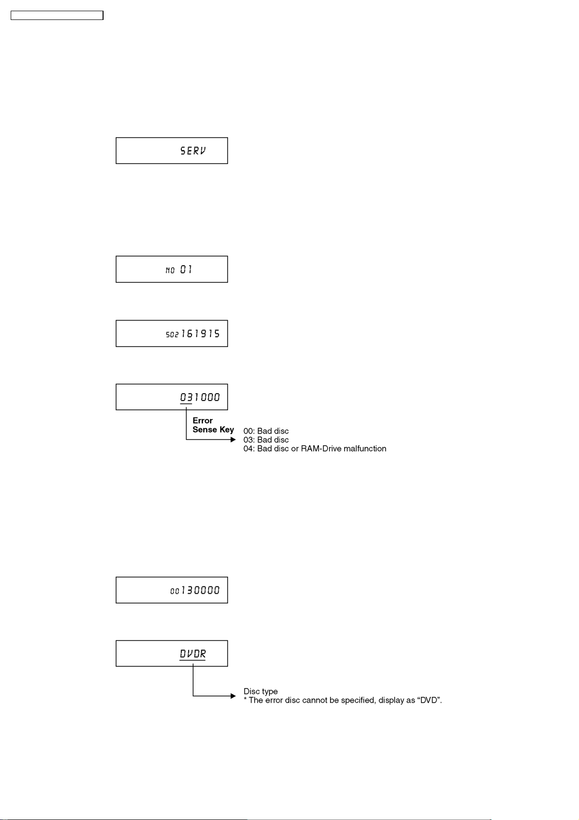
11 (DVD) SERVICE EXPLORER
Confirm “RAM-Drive Last Error” in Service Mode
Execute Service Mode
1. When the power is off, press [DVD DUBBING], [OPEN/CLOSE] and [STOP] keys simultaneously for 5 seconds.
FL Display:
*After finishing display “(7). Factor of Drive Error occurring”, press [0] [2] ~[1] [9] keys of the Remote Controller so that
19 memories can be displayed as maximum.
2. Press [4] [2] keys of remote controller.
Example of FL Display:
(1) Error Number is displayed for 5 seconds.
(2) Time when the error has occurred is displayed for 5 seconds.
(3) Last Drive Error (1/2) is displayed for 5 seconds.
When above error codes are displayed, confirm operation with Panasonic RAM disc or Panasonic DVD-R
disc.
* If the operation is OK, judge the error is due to media.
* If the operation is NG and symptom as BLOCK NOISES and so on, that are particular symptom of Digital
appears, judge the error is due to RAM-Drive or Digital P.C.B. .
(4) Last Drive Error (2/2) is displayed for 5 seconds.
(5) Error occurring Disc type is displayed for 5 seconds.
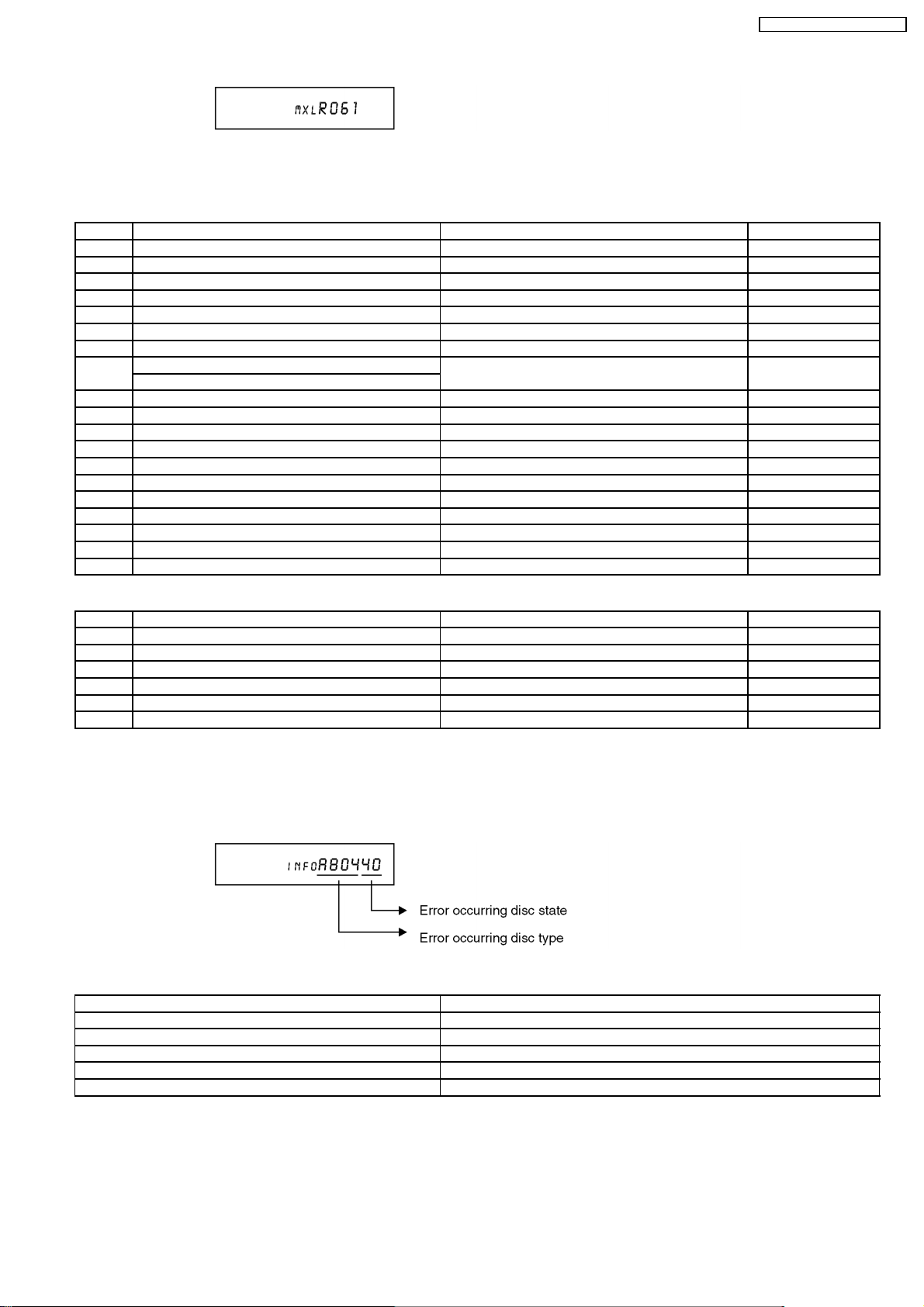
(6) Disc Maker´s ID is displayed for 5 seconds.
14
DMR-EH80VEG / DMR-EH80VEB
Example of Disc Maker´s ID:
DVD-R Disc
No. FL Display (Disc Maker´s ID) Disc Maker Country
1 MEI Panasonic Japan
2 PVC Pioneer Japan
3 MCC Mitsubishi Chemical Corporation Japan
4 TDK TDK Japan
5 MXL Maxell Japan
6 MCI MITUI CHEMICALS Japan
7 JVC Victor JVC Japan
8 TAIYOYUDEN Taiyo yuden Japan
TYG
9 GSC Giga Storage Taiwan
10 PRODISC Prodisc Taiwan
11 PRINCO PRINCO Taiwan
12 RITEK RITEK Taiwan
13 OPTDISC OPTDISC Taiwan
14 LEAD DATA LEAD DATA Taiwan
15 CMC CMC Taiwan
16 AUVISTAR AUVISTAR Taiwan
17 ACER Acer Taiwan
18 VIVASTAR VIVASTAR Switzerland
19 LGE LG Electronics Korea
DVD-RAM Disc
No. FL Display (Disc Maker´s ID) Disc Maker Country
1 MEI Panasonic
2 MATSUSHITA Panasonic Japan
3 MXL Maxell Japan
4 PRODISC Prodisc Taiwan
5 OPTDISC OPTDISC Taiwan
6 CMC CMC Taiwan
*Since an display is arbitrarily set up by the disk producer side, the above-mentioned display may be changed.
Please make it reference as an example of a display.
(7) Factor of Drive Error occurring is left displayed
Error Occurring Disc Type
FL Display Disc Type
00 DVD-ROM/Video
01 Audio-CD
02 2.6GB DVD-RAM
03 4.7GB DVD-RAM
04 DVD-R
15
DMR-EH80VEG / DMR-EH80VEB
Error Occurring Disc State
FL Displays
(Hexadecimal)
Disc distinction state Cartridge disc state Cartridge disc state Disc size
00 OK With cartridge Has not been opened yet. 12 cm
10 OK With cartridge Has not been opened yet. 8cm
20 OK With cartridge Has been opened. 12 cm
30 OK With cartridge Has been opened. 8cm
40 OK Bare Has not been opened yet. 12 cm
50 OK Bare Has not been opened yet. 8cm
60 OK Bare Has been opened. 12 cm
70 OK Bare Has been opened. 8cm
80 NG With cartridge Has not been opened yet. 12 cm
90 NG With cartridge Has not been opened yet. 8cm
A0 NG With cartridge Has been opened. 12 cm
B0 NG With cartridge Has been opened. 8cm
C0 NG Bare Has not been opened yet. 12 cm
D0 NG Bare Has not been opened yet. 8cm
E0 NG Bare Has been opened. 12 cm
F0 NG Bare Has been opened. 8cm
Description
16
DMR-EH80VEG / DMR-EH80VEB
12 (DVD) SELF-DIAGNOSIS AND SPECIAL MODE SETTING
12.1. (DVD) SELF-DIAGNOSIS FUNCTIONS
Self-Diagnosis Function provides information for errors to service personnel by “Self-Diagnosis Display” when any error has
occurred.
U**, H** and F** are stored in memory and held.
Display on FL will be cancelled when the power is turned off or AC input is turned off during self-diagnosis display is ON.
Error
Code
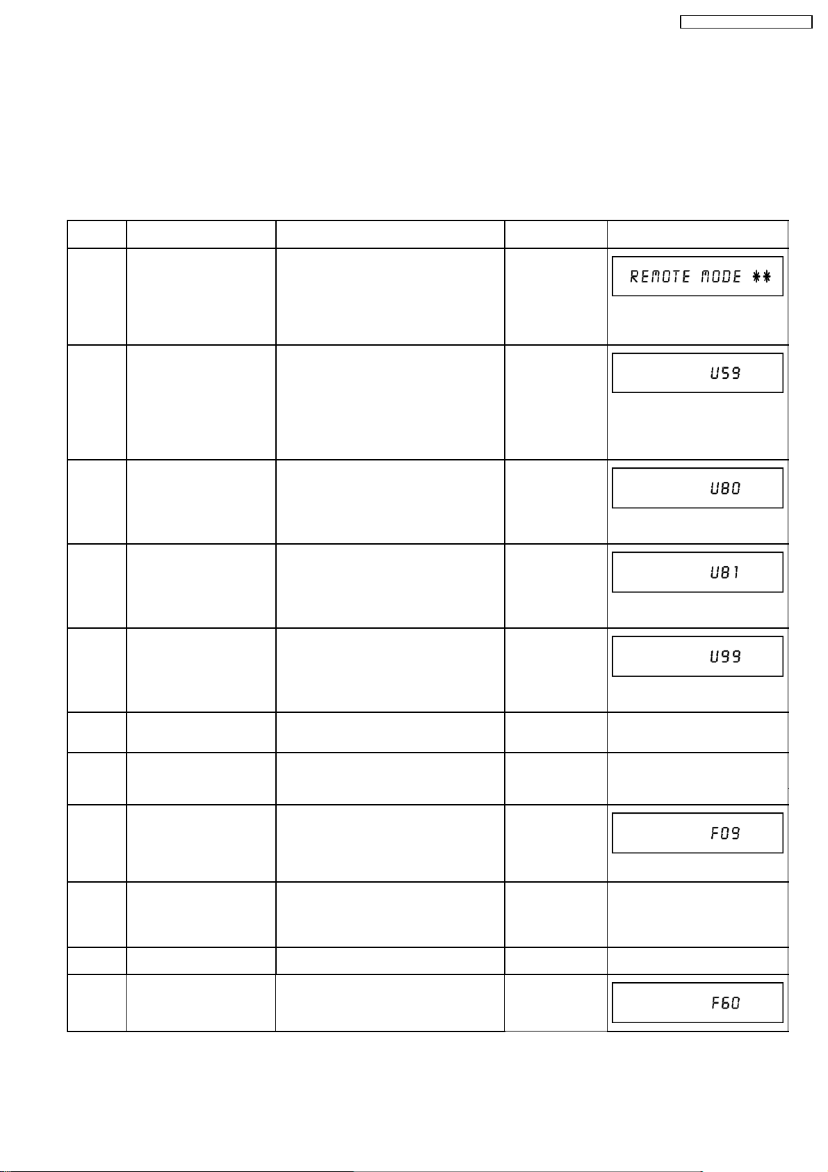
U30 Remote control code error Display appears when main unit and remote
U59 Abnormal inner temperature
U80 ST Microprocessor
Diagnosis contents Description Monitor Display FL display
No display
“*” is remote controller code of the
main unit.
Display for 5 seconds.
No display
“U59” is displayed for 30 minutes.
No display
detected
Communication Error on
Timer Bus
controller codes are not matched.
Display appears when the drive temperature
exceeds 70°C.
The power is turned off forcibly.
For 30 minutes after this, all key entries are
disabled. (Fan motor operates at the highest
speed for the first 5 minutes. For the
remaining 25 minutes, fan motor is also
stopped.) The event is saved in memory as
well.
Displayed appears when ST Microprocessor
Communication Error on Timer Bus occurs.
U81 ST Microprocessor
Communication Error on
UART
U99 Hang-up Displayed when communication error has
H19 Inoperative fan motor Display appears when inoperative fan motor
F00 No error information Initial setting for error code in memory
F09 Serial Communication Error
between VHS Micropressor
and Timer Microprocessor
F34 Initialization error when main
microprocessor is started up
for program recording
F58 Drive hardware error Display appears when drive unit error is
F60 DVD module has not been
started.
Displayed appears when ST Microprocessor
Communication Error on UART occurs.
occurred between Main microprocessor and
Timer microprocessor.
is detected after powered on.
The power is turned off when detecting.
(Error code Initialization is possible with error
code initialization and main unit
initialization.)
Please confirm Serial Communication
terminal of Microprocessor.
Note:
If F09 appears just after updating Firmware,
pull off and insert AC plug,
then it will disappear
Display appears when initialization error is
detected after starting up main
microprocessor for program recording. The
event is saved in memory.
The power is turned off when detecting.
detected. The event is saved in memory.
Defect of Digital P.C.B. .
Mode: No change
“U80” is displayed till Power Key is
pressed.
No display
“U81” is displayed till Power Key is
pressed.
No display
Displayed is left until the [POWER]
key is pressed.
No display No display
No display No display
No display
No display No display
No display No display
No display
17
DMR-EH80VEG / DMR-EH80VEB
Error
Diagnosis contents Description Monitor Display FL display
Code
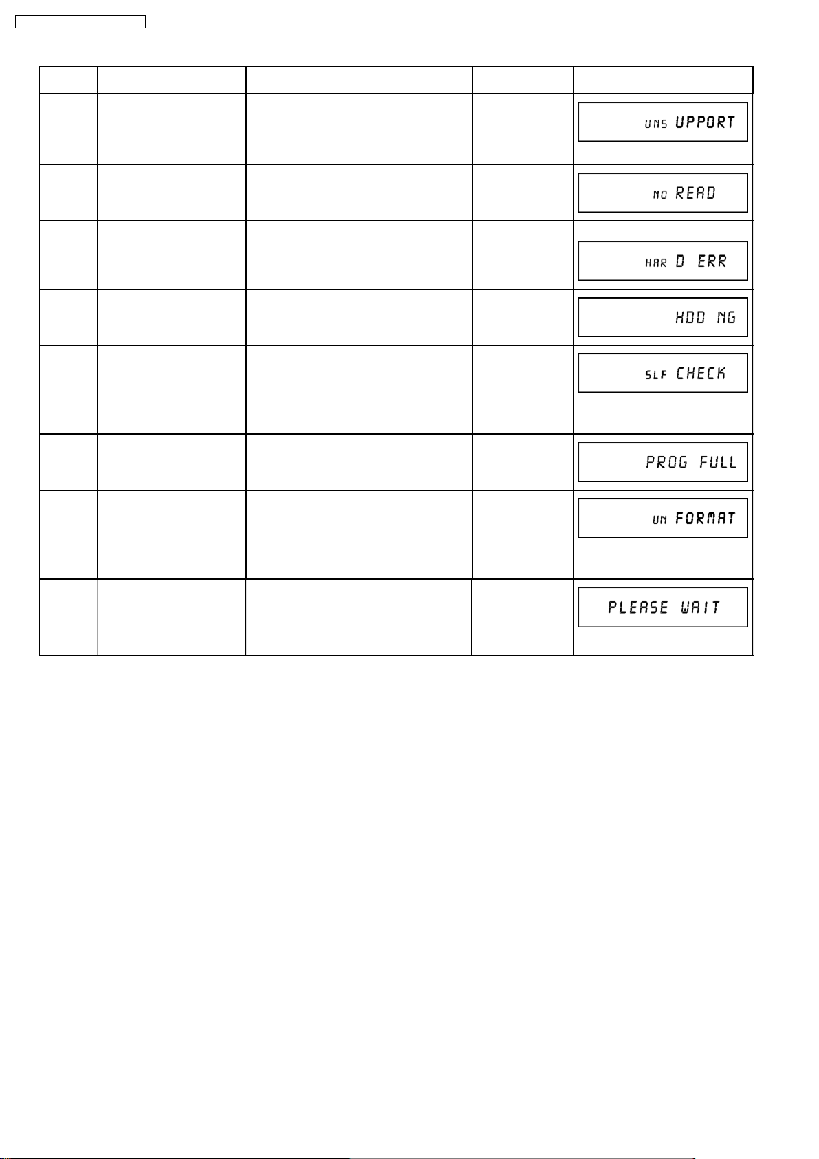
UNSUPPORT
Unsupported disc error *An unsupported format disc was played,
although the drive starts normally.
“This disc is
incompatible.”
*The data format is not supported, although
the media type is supported.
*Exceptionally incase of the disc is dirty.
NO READ Disc read error *A disc is flawed or dirty.
*A poor quality failed to start.
*The track information could not be read.
HARD
Drive error The drive detected a hard error. “DVD drive error.” Display for 5 seconds.
“Cannot read.
Please check the
disc.”
ERR
HDD NG HDD is NG HDD is NG. Please replace HDD. No display
SELF
CHECK
Restoration operation Since the power cord fell out during a power
failure or operation, it is under restoration
No display
operation.
*It will OK, if a display disappears
automatically. If a display does not
disappear, there is the possibility that
defective Digital P.C.B. / RAM drive.
Full
16 programs are already set. 16 programs are already set. No display
Program
Display for 5 seconds.
UNFORMAT
PLEASE
WAIT
The disc is not formatted You have inserted an unformatted DVD-
RAM or DVD-RW that is unformatted or
recorded on other equipment.
If you will use this disc, format is
necessary.
But, all program recorded on this disc
will be deleted.
Unit is in termination
process
Unit is in termination process now.
“BYE” is displayed and power will be turned
off.
In case “Quick Start” of setup menu is ON, it
is displayed in restoration operation for AC
off.
Format:
This disc is not
formatted properly.
Format the disc in
DISK
MANAGEMENT?
No display
18
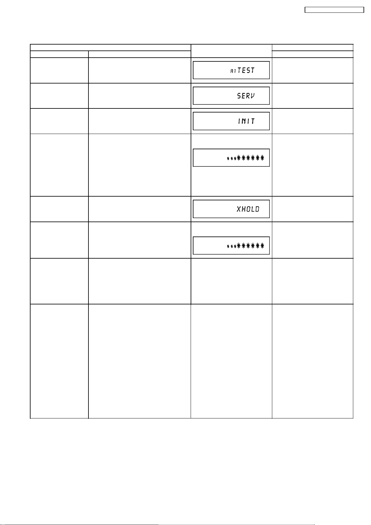
12.2. (DVD) SPECIAL MODES SETTING
Item FL display Key operation
Mode name Description Front Key
TEST Mode *All the main unit´s parameters (include
tuner) are initialized.
Service Mode Setting every kind of modes for servicing.
*Details are described in
“(DVD) Service Mode”.
Rating password The audiovisual level setting
password is initialized to “Level 8”.
Press [VHS to DVD DUBBING],
[OPEN/CLOSE] and [(DVD)REC]
keys simultaneously for five
seconds when power is off.
When the power is off, press [VHS
to DVD DUBBING],
[OPEN/CLOSE] and [(DVD) STOP]
keys simultaneously for 5 seconds.
While the tray is open, press
[(DVD) REC] and [(DVD) PLAY]
simultaneously for five seconds.
DMR-EH80VEG / DMR-EH80VEB
Forced disc eject Removing a disc that cannot be ejected.
The tray will open and unit will shift to P-off
mode.
*When Timer REC is ON or EXT-LINK is
ON, execute "Forced disc eject" after
releasing TimerREC or EXT-LINK.
*This command is not effective during “Child
lock” is ON.
If this command was executed while
TIMER REC is being set, TIMER REC
setting will turn to OFF.
Child lock/unlock Set or release "Child Lock". Press [ENTER] and [RETURN] by
NTSC/PAL system select To switch PAL/ NTSC alternately. The display before execution
Forced power-off When the power button is not effective while
power is ON, turn off the power forcibly.
*When Timer REC is ON, execute “Forced
Power-off” after releasing Timer REC or
EXT-LINK.
Action:
The tray will open, and the power will turn
off.
Aging Perform sequence of modes as * Aging
Description shown below continually.
Caution:
All programs in HDD and DVD-RAM disc
will be deleted because Formatting is
done once in Aging process.
The display before execution
leaves.
leaves.
Display in P-off mode. Press [Power] key over than 10
Display following the then mode. When the power is ON, press
When the power is off, press
[(DVD) STOP] and [(DVD) CH UP]
keys simultaneously for five
seconds.
remote controller simultaneously
until [X-HOLD] is displayed.
When the power is on (E-E mode),
press [DVD STOP] and
[OPEN/CLOSE] simultaneously for
five seconds.
seconds.
[STOP], [POWER] and
[OPEN/CLOSE] simultaneously for
over 5 seconds and less than 10
seconds.
NOTE1:
If Unit has not turned into Aging
mode by operations shown above,
execute TEST MODE once and
re-execute operation shown above.
(*All the main unit’s parameters
include tuner are initialized by
TEST mode.)
NOTE2:
If the unit has hung-up because of
pressing keys for over 10 seconds,
once turn off the power, and
re-execute this command.
*When releasing Aging mode,
press [POWER] key.
19
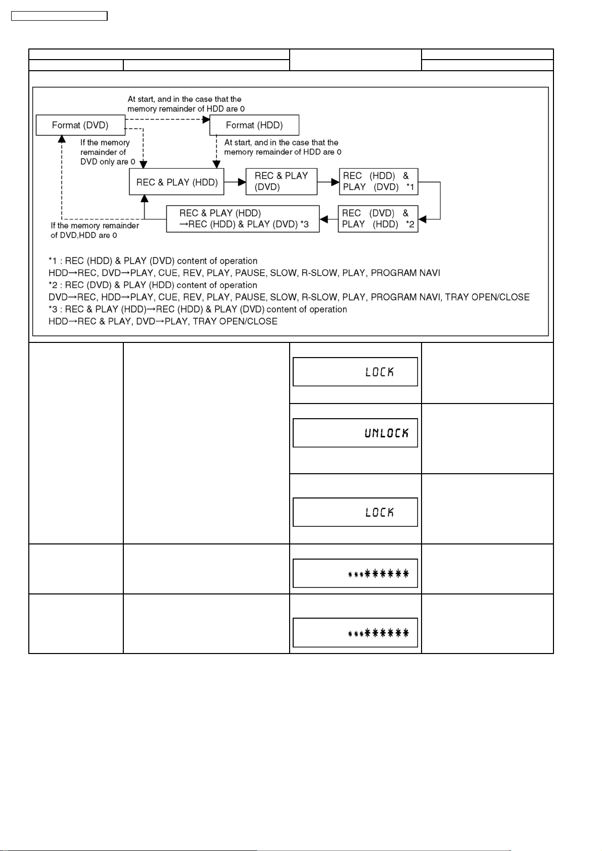
DMR-EH80VEG / DMR-EH80VEB
Mode name Description Front Key
Aging Contents (Example):
Item FL display Key operation
Demonstration
lock/unlock
Ejection of the disc is prohibited.
The lock setting is effective until unlocking
the tray and not released by “Main unit
*When lock the tray.
When the power is on, press
[(DVD) STOP] and [POWER] keys
simultaneously for five seconds.
initialization” of service mode.
“LOCK” is displayed for 3 seconds.
*When unlock the tray.
When the power is on, press
[(DVD) STOP] and [POWER] keys
simultaneously for five seconds.
“UNLOCK” is displayed for 3
seconds.
*When pressing [OPEN/CLOSE]
key while the tray is locked.
Press [OPEN/CLOSE] key while
the tray is locked.
Display “LOCK” for 3 seconds.
ATP re-execution Re-execute ATP. When the power is on (E-E mode),
press [(DVD) CH UP] and [(DVD)
CH DOWN] simultaneously for five
seconds.
Progressive initialization The progressive setting is initialized to
Interlace.
The display before execution
leaves.
When the power is on (E-E mode),
press [VHS to DVD DUBBING] and
[(DVD) STOP] simultaneously for
five seconds.
20
DMR-EH80VEG / DMR-EH80VEB
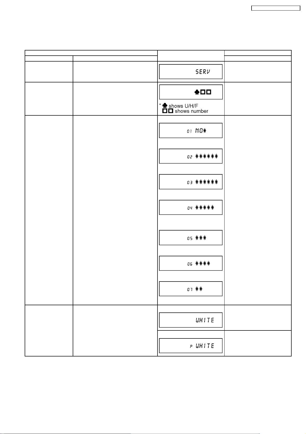
12.3. (DVD) SERVICE MODES
Service mode setting: While the power is off, press [DVD DUBBING], [OPEN/CLOSE] and [DVD STOP] keys simultaneously for
five seconds.
Item FL display Key operation
Mode name Description (Remote controller key)
Release Items Item of Service Mode executing is cancelled. Press [0] [0] or [Return] in service
mode.
Error Code Display Last Error Code of U59/H/F held by Timer is
displayed on FL.
*Details are described in
“(DVD) Self-Diagnosis Functions”.
ROM Version Display (01)Region code,
(02)MAIN firmware version,
(03)TIMER firmware version,
(04)DRIVE firmware version,
(05)ROM correction version,
(06)VHS microprocessor version are
displayed on FL for five seconds per each
version in order, but
(07)VHS ROM correction version will be left
displayed.
(01)Region code
(02)MAIN firmware version
(03)TIMER firmware version
(04)DRIVE firmware version
(05)ROM correction version+ROM
Type
Press [0] [1] in service mode
Press [0] [2] in service mode
White Picture Output White picture is output as component Output
from AV Decoder.
*White picture
(Saturation rate: 100%)
*It is enable to switch Interlace/Progressive
by “I/P Switch: [1] [4]”
(06)VHS microprocessor version
(07)VHS ROM correction version
* are version displays
*Initial mode is “Interlace”. Press [1] [1] in service mode.
Switch Interlace/Progressive Press [1] [4] in White Picture Output
mode.
*I/P are switched alternately.
21
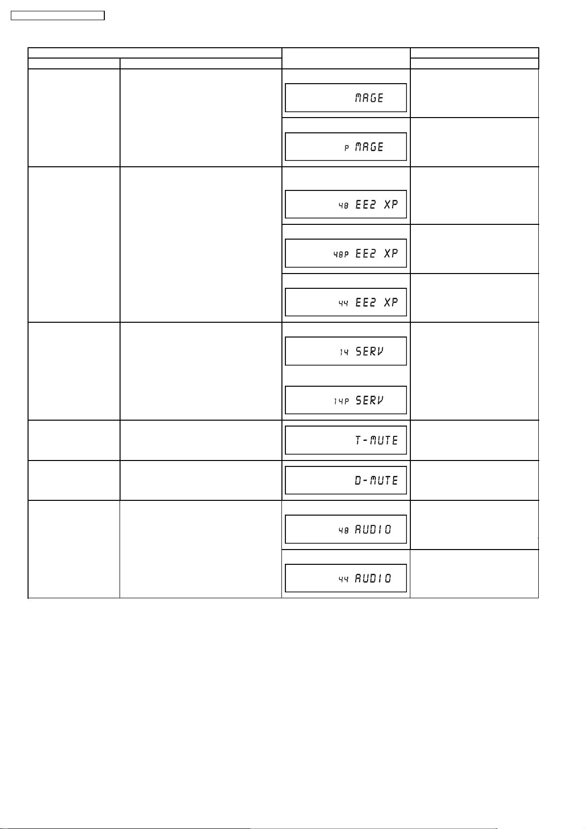
DMR-EH80VEG / DMR-EH80VEB
Item FL display Key operation
Mode name Description (Remote controller key)
Magenta Picture Output Magenta picture is output with Component
Output from AV Decoder.
*Magenta picture
(Saturation rate: 100%)
*It is enable to switch Interlace/Progressive
by “I/P Switch: [1] [4]”
*Initial mode is “Interlace”. Press [1] [2] in service mode.
Switch Interlace/Progressive Press [1] [4] in Magenta Picture
Output mode.
*I/P are switched alternately.
RTSC Return in XP
(A & V)
AV1 input signal is encoded (XP), decoded
(XP) and output decoded signal to external
without DISC recording and DISC playback.
I/P Switch Switch Interlace and Progressive in EE
mode.
*Initial setting is “Interlace”.
*This command is effective during executing
“White Picture Output”, “Magenta Picture
Output” and “RTSC Return in XP (A & V)”
modes.
Audio Mute (XTMUTE) Check whether mute is applied normally by
the timer microprocessor.
Initial mode: EE2/ Interlace/ XP/
Press [1] [3] in service mode.
Audio 48kHz
Switch Interlace/Progressive Press [1] [4] in RTSC Return XP
mode.
*I/P are switched alternately.
Audio 44.1 kHz/ 48 kHz Switch Press [2] [4] in RTSC Return XP
mode.
*48 kHz / 44.1 kHz are switched
alternately.
Initial mode is Interlace
Press [1] [4] in I/P Switch mode.
*I/P are switched alternately.
Switch Interlace/Progressive
Press [2] [1] in service mode.
Audio Mute (XDMUTE) Check whether mute is applied normally by
the Digital P.C.B. (GLUE IC).
Audio Pattern Output The audio pattern stored in the internal
memory is output
(Lch: 1kHz/-18dB)
(Rch: 400Hz/-18dB)
*Audio sound clock switching operation of
DAC can be confirmed by sub command [2]
[4].
Press [2] [2] in service mode.
Initial mode (Audio 48kHz) Press [2] [3] in service mode.
Audio 44.1kHz/48kHz switching Press [2] [4] in Audio Pattern
Output mode.
*48 kHz / 44.1 kHz are switched
alternately.
22

Item FL display Key operation
Mode name Description (Remote controller key)
HDD READ inspection Perform a complete read inspection of the
HDD.
When the HDD is OK
Press [3] [1] in the service mode.
* When canceling the checking
mode while executing, do “forced
power-off”.
Method: Press the “POWE” button
If the HDD is defective
more than 10 seconds.
: Judge of Forward rate.
* When normal (Forward rate is 35
Mbps or more and there is no HDD
error):
is Space.
* When Abnormal (Forward rate is
less than 35 Mbps or HDD error
existing):
is X.
: Number of what have
spent time for seeking is over
100ms.
* When normal:
are spaces.
* When Abnormal: Display Number
of what have spent time fore
seeking over 100 ms.
However, if the number is more
than 100, display [XX].
We judge it is normal that the
number is less than 4.
Laser Used Time
Check laser used time (hours) of drive.
Press [4] [1] in service mode.
Indiction
DMR-EH80VEG / DMR-EH80VEB
Delete the Laser Used
Time
Laser used time stored in the memory of the
unit is deleted.
●(*****) is the used time display in
hour.
●Laser used time of DVD/CD in
Playback/Recording mode is
counted.
Press [9] [5] in service mode.
23
DMR-EH80VEG / DMR-EH80VEB
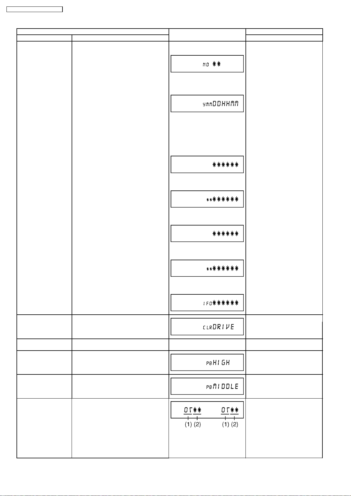
Item FL display Key operation
Mode name Description (Remote controller key)
RAM Drive Last Error RAM Drive error code display.
*For details about the drive error code, refer
to the Service Manual for the specific RAM
Drive.
*Details are described in
“(DVD) Service Explorer”.
1. Error Number is displayed for 5
seconds.
2. Time when the error has
occurred is displayed for 5
seconds.
Y: Year
MM: Month
DD: Day
hh: Hour
mm: Minute
3. Last Drive Error (1/2) is
displayed for 5 seconds.
4. Last Drive Error (2/2) is
displayed for 5 seconds.
Press [4] [2] in service mode.
Then press [0] [1] ~ [9] [9], the
past 99 errors are displayed.
Delete the Last Drive
Error
Delete the Last Drive Error information
stored on the DVD RAM-Drive.
Turn on all FL/LEDs All segments of FL and all LEDs are turned
on.
PB HIGH Signal Output 8 pin of AV 1 Jack (PB HIGH terminal) is
High (approx. 11V DC).
PB MIDDLE Signal
Output
8 pin of AV 1 Jack (PB HIGH terminal) is
Middle (approx. 5.5V DC).
5. Error occurring Disc type is
displayed for 5 seconds.
6. Disc Maker ID is displayed for 5
seconds.
In case that the supplier cannot be
identified, display is black out.
7. Factor of Drive Error occurring is
left displayed
Press [9] [6] in service mode.
All segments are turned on. Press [5] [1] in service mode.
Press [5] [2] in service mode.
Press [5] [3] in service mode.
Front connection
inspection
Press all front keys and check the
connection between Main P.C.B. and Front
P.C.B.
Press [5] [4] in service mode.
(1) Each time a key is pressed,
segment turned on increases one
by one.
(2) Total umber of keys that have
been pressed.
24
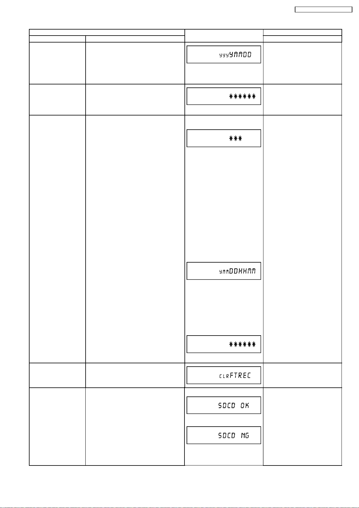
Item FL display Key operation
Mode name Description (Remote controller key)
Production Date Display Display the date when the unit was produced.
Press [6] [1] in service mode.
YYY: Year
MM: Month
DD: Day
Display the accumulated
Display the accumulated unit´s working time.
Press [6] [4] in service mode.
working time
(Indicating unit: Second)
Display the Error History Display the Error History stored on the unit. Display reason of error for 5
seconds.
Press [6] [5] in service mode.
Then press [0] [1] ~ [1] [9], the past
19 error histories are displayed.
Description of Error Numbers
NO FTREC: No error
01:
Defect of Digital P.C.B.
(AV DEC/MAIN CPU)
02:
Defect of RAM Drive
03:
Defect of Disc
04:
Defect of Digital P.C.B. or
Communication Error
05:
Defect of Digital P.C.B.
(AV DEC/MAIN CPU)
06:
Defect of HDD
DMR-EH80VEG / DMR-EH80VEB
Delete the Error History Delete Error History information stored on
the unit.
SD card WRITE check Check SD card WRITE function with SD card
slot.
Display the time when the error
has occurred for 5 seconds.
Y: Year
MM: Month
DD: Day
HH: Hour
MM: Minute
Display the accumulated working
time to occurring of the error for 5
seconds.
(Indicating unit: Second)
When the WRITE check is OK.
When the WRITE check is NG.
Press [9] [7] in service mode.
Insert a SD card to SD card slot,
and press [7] [4] in service mode.
* Insert SD card while the power is
off.
* Check for [CARD SD] display on
the FL display and go on the
procedure.
*Note:
The image stored in the SD
card will be erased.
25
DMR-EH80VEG / DMR-EH80VEB
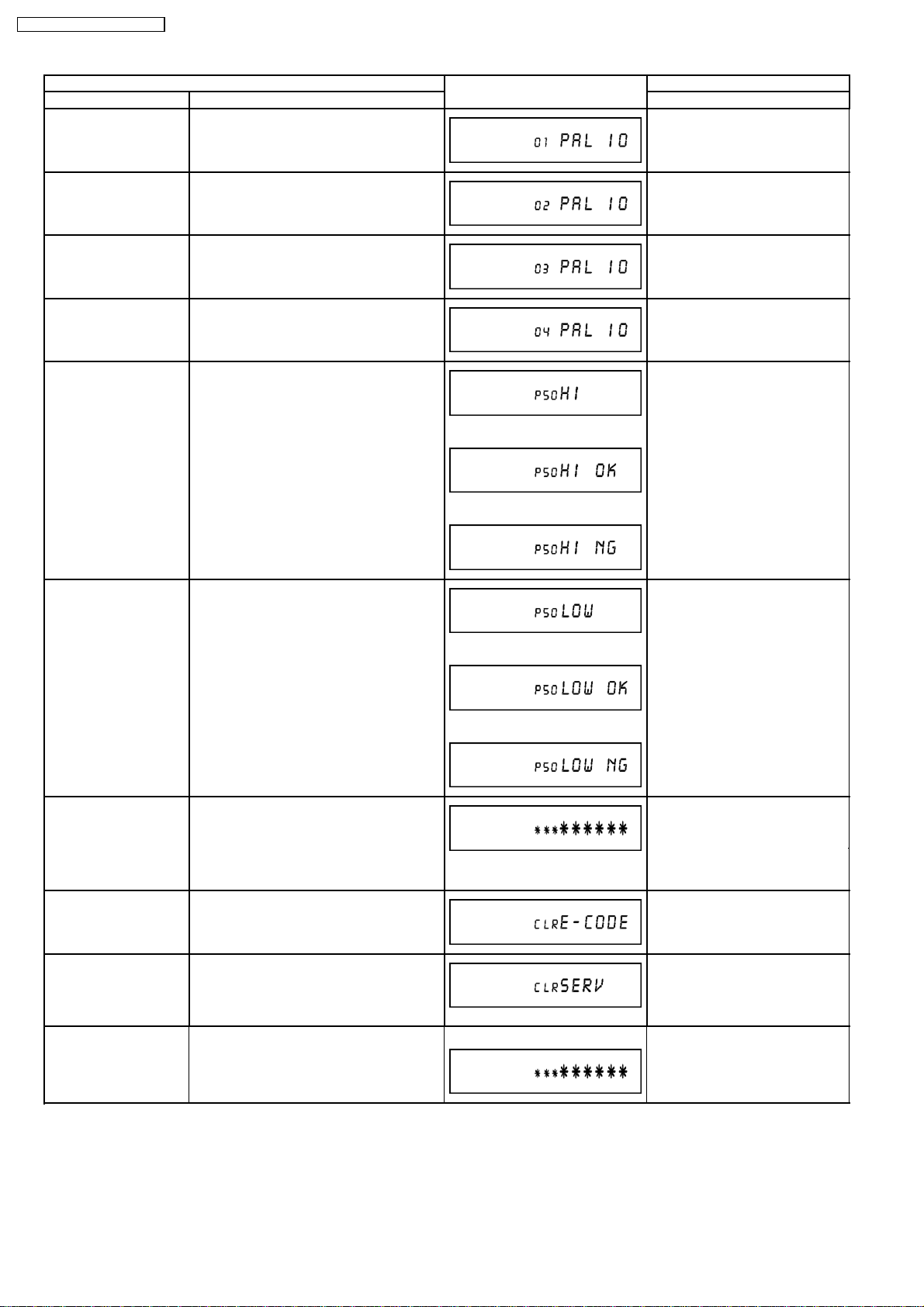
Mode name Description (Remote controller key)
AV4 (V) / AV1 (RGB) I/O
Setting
Item FL display Key operation
Set input to AV4(V) and set output to
Press [8] [0] in service mode.
AV1(RGB) for I/O checking
AV2 (Y/C) / AV1 (V) I/O
Setting
AV2 (V) / AV1
(Y/C) I/O Setting
AV2 (RGB) /
AV1 (V) I/O Setting
Set input to AV2(Y/C) and set output to
AV1(V) for I/O checking
Set input to AV2(V) and set output to
AV1(Y/C) for I/O checking
Set input to AV2(RGB) and set output to
AV1(V) for I/O checking
P50 (H) Output Timer Microprocessor IC7501-22 output
High signal for AV1-pin 10 passing through
inverter (approx. 0V DC at AV1-pin 10).
P50 (L) Output Timer Microprocessor IC7501-22 output Low
signal for AV1-pin 10 passing through
inverter (approx. 4.4 V DC at AV1-pin 10).
Press [8] [1] in service mode.
Press [8] [2] in service mode.
Press [8] [3] in service mode.
Press [8] [4] in service mode.
When OK.
When NG.
Press [8] [5] in service mode.
When OK.
When NG.
Tray OPEN/CLOSE Test The RAM drive tray is opened and closed
repeatedly.
Press [9] [1] in service mode
*When releasing this mode, press
the [POWER] button on Front
Panel more than 10 seconds.
“*” is number of open/close cycle
times.
Error code initialization Initialization of the last error code held by
Press [9] [8] in service mode.
timer (Write in F00)
Initialize Service Last Drive Error, Error history and Error
Press [9] [9] in service mode.
Codes stored on the unit are initialized to
factory setting.
Then VHS Microprocessor is initialized to
shipping setting too.
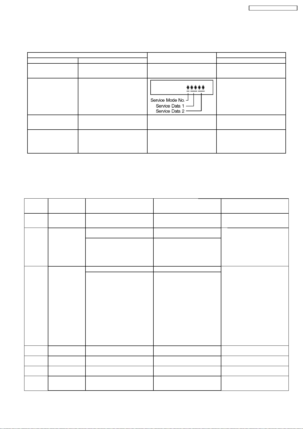
Finishing service mode Release Service Mode. Display in STOP (E-E) mode. Press power button on the front
panel in service mode.
26
DMR-EH80VEG / DMR-EH80VEB
13 (VHS) SELF-DIAGNOSIS AND SPECIAL MODE SETTING
13.1. (VHS) SPECIAL MODES SETTING
Item FL display Key operation
Mode name Description Front Key
Tracking Center Tape Tracking is adjusted to center
FIX position.
VHS Service Mode In order to make service easy, a part
of inside information of a
microprocessor is displayed on FIP.
*Details are described in
"VHS Service Mode".
No display. During PLAYBACK, press [VHS CH
UP] and [VHS CH DOWN] keys
simultaneously.
Press [FF], and [EJECT] keys
simultaneously for three seconds
when power is off.
Releasing EXT LINK &
Timer Program
Eject Ejecting Cassette Tape No display. While in other than Timer REC
Releasing Continuation EXT LINK &
Continuation Timer Program
No display. While in EXT LINK or Timer REC
mode, press [VHS STOP] key for 3
seconds.
mode, press [VHS STOP] key for 3
seconds or press [STOP] key of the
Remote Controller for 3 seconds in
VHS mode.
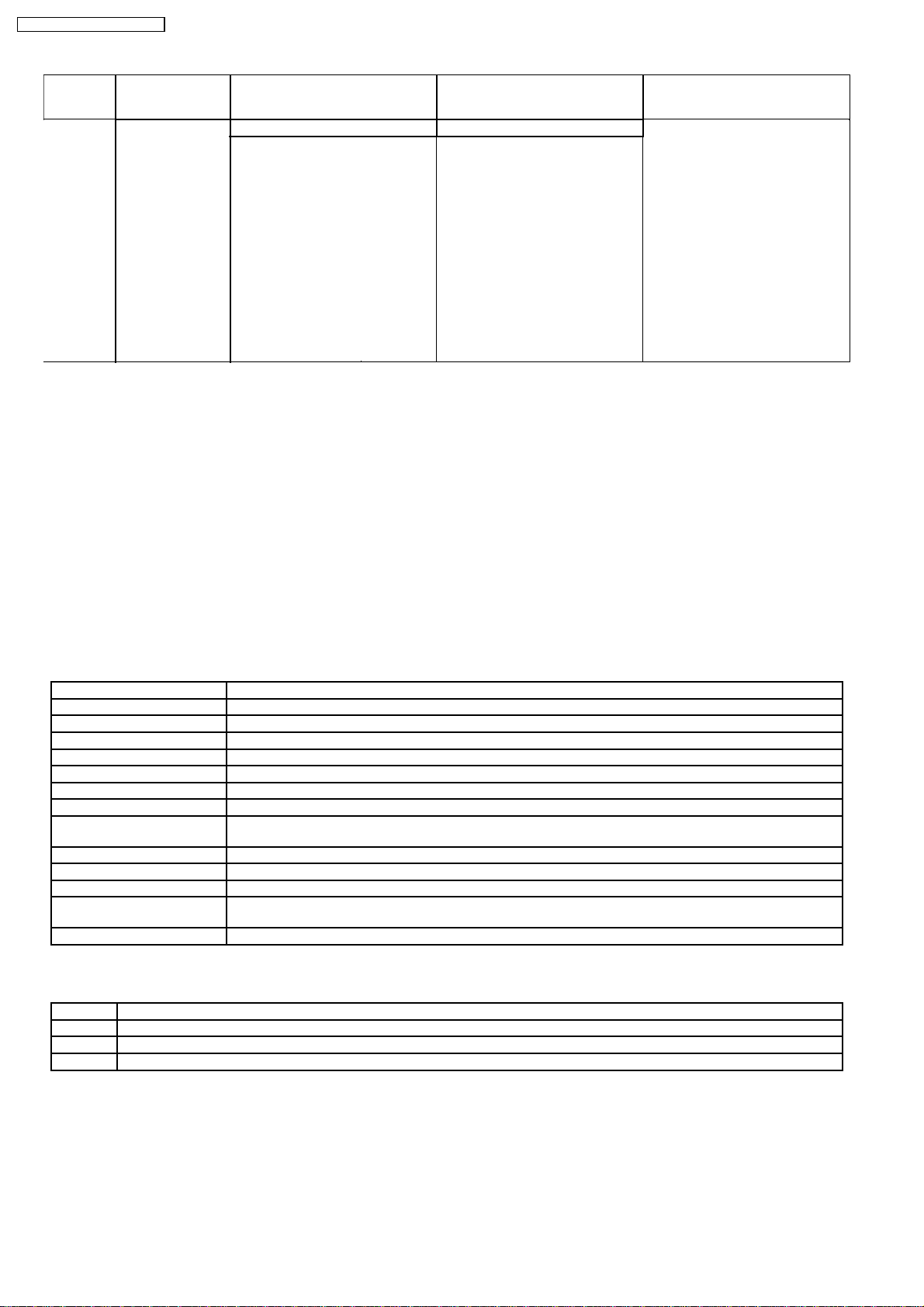
13.2. (VHS) SERVICE MODES
(Service Mode Setting)
1. When power is OFF, press [FF] and [EJECT] keys simultaneously for 3 seconds to into Service Mode.
2. In Service Mode, press [FF] and [EJECT] keys simultaneously to add Service Number.
Service
Mode
Number
0 Indication for the
1 Indication for the
2 Indication for the
3 Self-diagnosis
4 Self-diagnosis
5 Self-diagnosis
6 Indication for the
Contents Contents of Indication
inner data of
IC6001
inner data of
IC6001
inner data of
IC6001
history (1st)
history (2nd)
history (3rd)
inner data of
IC6001
VHS mode
(Real time)
Tape beginning and ending
detection data (Real time)
00: Both tape beginning and ending
have not been detected
01: Tape ending is detecting now
02: Tape beginning is detecting now
03: Both tape beginning and ending
are detecting now
Mechanism position (Real time) Ordering for the Motors (Real time) The following functions are
0L: EJECT position
02: DOWN position
03: RREW position
04: LOAD position
05: REV position
06: PLAY position
07: POFF position
08: STOP_R position
09: STOP_F position
0- : FF/REW position
0_ : Intermediate between each
positions
1st history of error number "- -" is displayed.
2nd history of error number "- -" is displayed
3rd history of error number "- -" is displayed
Servo data (4 digits)
(Real time)
on minute
Contents of Indication
on second
Process number of the mechanism
movement
(Real time)
Key code
(Real time)
Indicate the receiving code when
the key of VCR or remote controller
being operated.
0*, 2*: CYL off,
CAP off
1*: CYL off,
CAP on (fwd)
3*: CYL off,
CAPon (rev)
8*, A*: CYL on,
CAP off
9*: CYL on,
CAPon (fwd)
B*: CYL on,
CAP on (rev)
*0: Motor off
*1:Loading
*2: Unloading
*3: Break (Load + Unload)
Remarks
prohibited to operate the
mechanism without cassette tape.
●Tape beginning and ending
detection.
●Reel lock detection
●Tape detection and tape position
detection
Press the EJET key for over 3
seconds in this mode, and then the
VCR is shifted into the special
modes, such as PG Adjustment,
Model Code Setting, and so on.
The orders for the motors are
asfollows.
27
DMR-EH80VEG / DMR-EH80VEB
Service
Mode
Number
7 Manual mechanism
Contents Contents of Indication
operation
Mechanism position (Real time) Ordering for the Motors Press the following key;
0L: EJECT position
02: DOWN position
03: RREW position
04: LOAD position
05: REV position
06: PLAY position
07: POFF position
08: STOP_R position
09: STOP_F position
0- : FF/REW position
0 _: Intermediate between each
positions
on minute
Contents of Indication
on second
0*, 2*: CYL off,
CAP off
1*:CYL off,
CAP on (fwd)
3*: CYL off,
CAPon (rev)
8*, A*: CYL on,
CAP off
9*: CYL on,
CAPon (fwd)
B*: CYL on,
CAP on (rev)
*0: Motor off
*1:Loading
*2: Unloading
*3: Break (Load + Unload)
Remarks
PLAY key: Loading
STOP key: Unloading
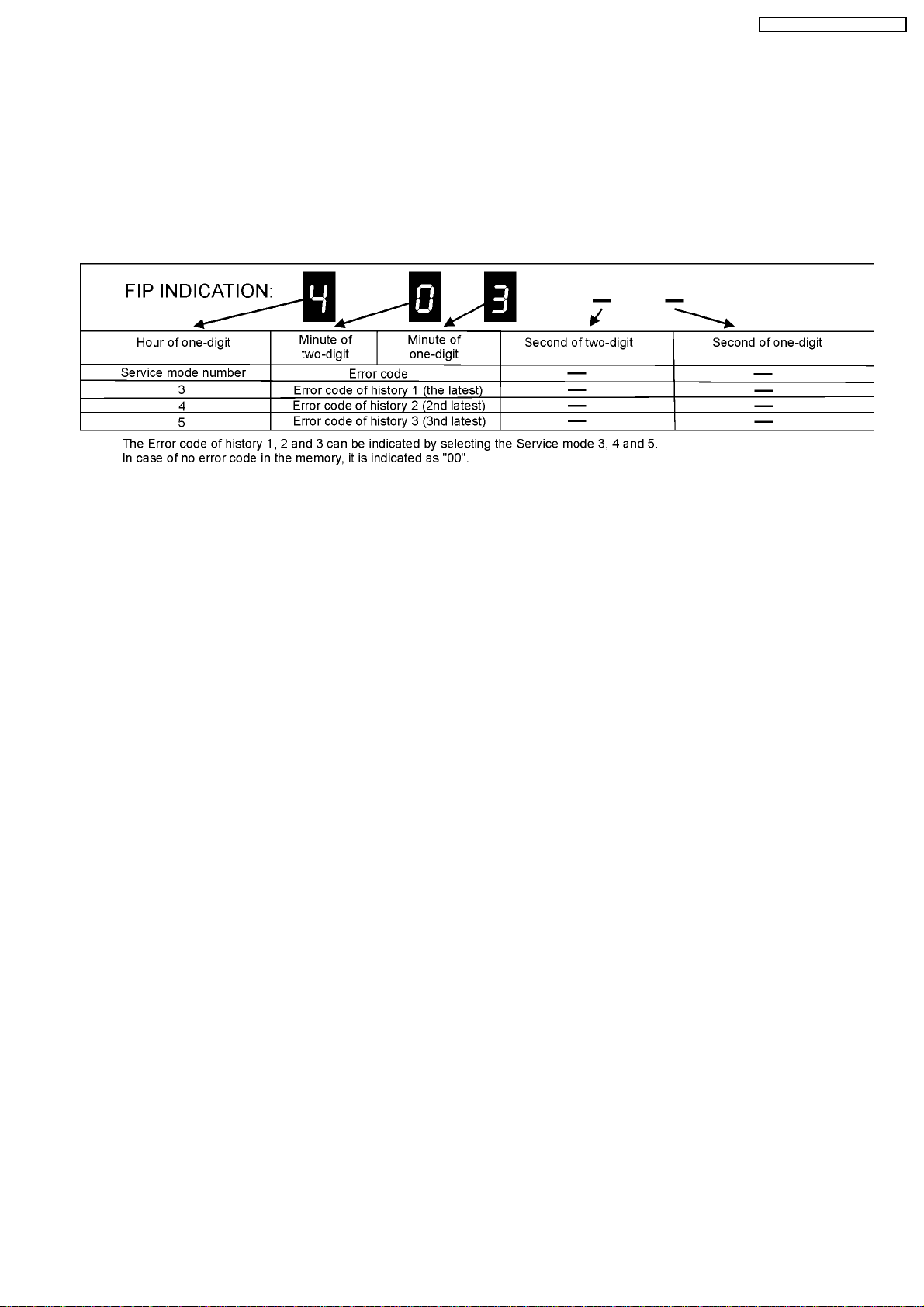
13.3. (VHS) SELF-DIAGNOSIS FUNCTIONS
This model has a self-diagnosis. If the VHS section detects trouble during installation or during use, the power is automatically
turned off or become power-save mode and it is memorized into the EEPROM (IC37502) as error code of two-digit number. It´s
memorized error code can be displayed in "second" display portion (the last 2 digits of the FIP) by placing the unit is Service Mode
Number 2 when turning on the Service Information Display as for example "01" or "02" etc. as below. If a second error occurs, the
most recent error will be memorized and can be displayed in Service Mode Number 2. It can be memorized until 3 self-diagnosis
histories in maximum.
In order to erase the memorized error code, press FF and EJECT buttons on the Front Panel simultaneously over 5 seconds during
turning on Service Information Display mode.
13.3.1. MEMORY OF THE SELF-DIAGNOSIS HISTORY
*This is effective only in Service Mode 3, 4, 5.
13.3.1.1. ERROR NUMBERS AT A GLANCE
Memory No. (Error Code) Reason
01 The cylinder could not be started. (Error of the cylinder or the cylinder driver.)
02 The CAP FG could not be detected.
03 Mechanism lock during without the unloading and the cassette-up.
04 Mechanism lock during unloading
05 S-reel pulse cannot be detected during unloading. (Error of the S-reel circuit or the Capstan circuit)
06 Mechanism lock during the Cassette-up.
09 Communication Error between VHS Microprocessor and Timer Microprocessor.
15 S-reel pulse cannot be detected when a cassette tape is inserted.
16 Detection of the Cylinder lock during the constant rotation
17 Detection of S-reel lock during the constant tape running
18 Detection of T-reel lock during the constant tape running
2*
Refer to following table
80 An exceptional ejection depends on a accidental error
Note:
2* is as follows.
20 NG1 in the PG Shifter Automatic Adjustment (The cylinder rotation is unstable during the automatic adjustment.)
21 NG2 in the PG Shifter Automatic Adjustment (The vertical sync signal is lacked while over 5 seconds on the alignment tape.)
22 NG3 in the PG Shifter Automatic Adjustment (The installing position of Heads to the cylinder is our of specification.
23 NG4 in the PG Shifter Automatic Adjustment (The servo is not locked to the cylinder for more than 10 sec.)
(Error of the S-reel circuit or the Capstan circuit)
An error while the PG Automatic Adjustment
13.3.1.2. MEMORY FOR THE SELF-DIAGNOSIS HISTORY
3. The self-diagnosis result is memorized the state of the moment of detecting.
4. There are the histories from number 1 to number 3.
5. The latest error is memorized on history number 1, and then the old histories are shifted to the history number 2 and 3.
The error code memorized in the history number 2 and 3 is over-written by shift.
28
DMR-EH80VEG / DMR-EH80VEB
4. If the latest error is the same with the history number 1 (2nd-latest), it is not memorized.
(The same error code is not memorized in succession)
13.3.1.3. CLEAR FOR THE SELF-DIAGNOSIS HISTORY
1. Press FF and EJECT buttons on the VCR simultaneously over 5 seconds during turning on Service Information Display mode.
13.3.1.4. INDICATION OF THE SELF-DIAGNOSIS HISTORY
The self-diagnosis histories can be indicated on the FIP with Service Mode number 3 to 5.
The procedure of service mode setting and indication format are the same as usual.
29
DMR-EH80VEG / DMR-EH80VEB
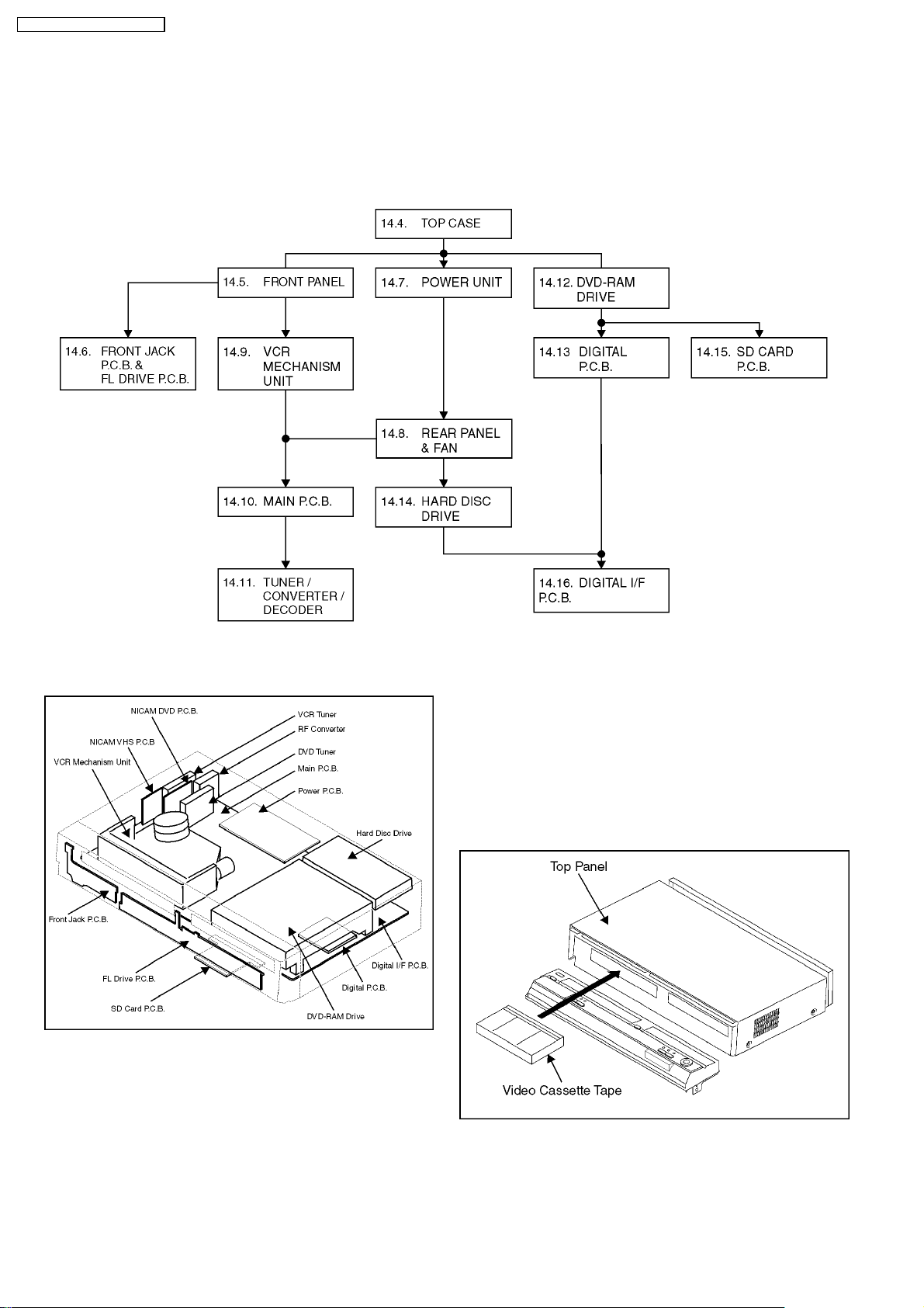
14 ASSEMBLING AND DISASSEMBLING
14.1. DISASSEMBLY FLOW CHART
The following chart is the procedure for disassembling the casing and inside parts for internal inspection when carrying out the
servicing. To assemble the unit, reverse the steps shown in the chart below.
14.2. P.C.B. POSITIONS 14.3. CAUTION WHILE INSERTING
CASSETTE TAPE WHEN
DISASSEMBLING THE UNIT
NOTE:
Video Cassette might not enter when a strong lighting is
applied to VHS Mechanism when Video Cassette is
inserted. Please weaken the lighting or cover with the top
panel etc.
30
 Loading...