

Page 1
ORDER NO. PCZ1703034CE
Blu-ray Disc Player
Model No. DMP-UB300EB
DMP-UB300EG
DMP-UB310EG
DMP-UB314EG
DMP-UB390EB
Colour
(K)....................Black Type
© Panasonic Corporation 2017.
Unauthorized copying and distribution is a violation
of law.
Page 2

TABLE OF CONTENTS
PAG E PAG E
1 Safety Precautions -----------------------------------------------3
1.1. General Guidelines ----------------------------------------3
1.2. Leakage Current Cold Check ---------------------------3
1.3. Leakage Current Hot Check (See Figure 1.) --------3
2Warning--------------------------------------------------------------4
2.1. Prevention of Electrostatic Discharge (ESD)
to Electrostatically Sensitive (ES) Devices ----------4
2.2. Caution for AC Cord (For EB)---------------------------5
2.3. Precaution of Laser Diode -------------------------------6
2.4. General Description About Lead Free Solder
(PbF) ----------------------------------------------------------7
2.5. Static Electricity Protection Measures ----------------8
2.6. Ground for electrostatic breakdown
prevention----------------------------------------------------8
3 Service Navigation------------------------------------------------9
3.1. Service Infomation -----------------------------------------9
3.2. How to Update Firmware---------------------------------9
4 Specifications ---------------------------------------------------- 12
4.1. Others (Licenses) ---------------------------------------- 15
5 Location of Controls and Components------------------ 16
6 Operating Instructions ---------------------------------------- 18
6.1. Taking out the Disc from Drive Unit when the
Disc cannot be ejected by OPEN/CLOSE
button-------------------------------------------------------- 18
6.2. Micro Fuse Conducting Check------------------------ 19
7 Service Mode ----------------------------------------------------- 20
7.1. About the Multiple Pressing of the Unit’s
Remote Control------------------------------------------- 20
7.2. How to enter the Special Modes using the
Multiple Pressing Function of the Unit’s
Remote Control------------------------------------------- 20
7.3. About the Service Mode -------------------------------- 23
7.4. Service Mode List ---------------------------------------- 24
7.5. Self-Diagnostics Functions ---------------------------- 27
8 Service Fixture & Tools --------------------------------------- 29
9 Disassembly and Assembly Instructions --------------- 30
9.1. Unit----------------------------------------------------------- 30
9.2. Sticking position of Barrier Sheet -------------------- 35
10 Measurements and Adjustments -------------------------- 36
10.1. Service Positions ----------------------------------------- 36
10.2. Adjustment of Drive Unit ------------------------------- 38
10.3. Caution for Replacing Parts ---------------------------39
11 Block Diagra m --------------------------------------------------- 40
11.1. Overall Block Diagram ----------------------------------40
11.2. Power Supply Circuit Block Diagram---------------- 41
11.3. Digital P.C.B. Unit Regulator Circuit Block
Diagram----------------------------------------------------- 42
11.4. Timer Circuit Block Diagram--------------------------- 43
11.5. Digital Circuit Block Diagram -------------------------- 44
12 Wiring Connection Diagram --------------------------------- 45
12.1. Interconnection Diagram ------------------------------- 45
13 Schematic Diagram--------------------------------------------- 46
14 Printed Circuit Board ------------------------------------------ 46
15 Exploded View and Replacement Parts List -----------46
2
Page 3
1 Safety Precautions
1.1. General Guidelines
1. IMPORTANT SAFETY NOTICE
There are special components used in this equipment
which are important for safety. These parts are marked by
in the Schematic Diagrams, Circuit Board Layout,
Exploded Views and Replacement Parts List. It is essential that these critical parts should be replaced with manufacturer’s specified parts to prevent X-RADIATION,
shock, fire, or other hazards. Do not modify the original
design without permission of manufacturer.
2. An Isolation Transformer should always be used during
the servicing of AC Adaptor whose chassis is not isolated
from the AC power line. Use a transformer of adequate
power rating as this protects the technician from accidents resulting in personal injury from electrical shocks. It
will also protect AC Adaptor from being damaged by accidental shorting that may occur during servicing.
3. When servicing, observe the original lead dress. If a short
circuit is found, replace all parts which have been overheated or damaged by the short circuit.
4. After servicing, see to it that all the protective devices
such as insulation barriers, insulation papers shields are
properly installed.
5. After servicing, make the following leakage current
checks to prevent the customer from being exposed to
shock hazards.
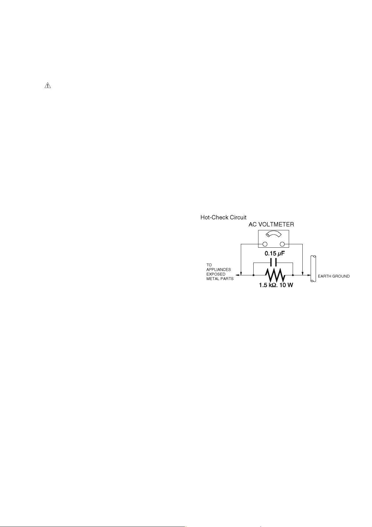
1.3. Leakage Current Hot Check (See Figure 1.)
1. Plug the AC cord directly into the AC outlet. Do not use
an isolation transformer for this check.
2. Connect a 1.5 kΩ, 10 W resistor, in parallel with a 0.15 μF
capacitor, between each exposed metallic part on the set
and a good earth ground, as shown in Figure 1.
3. Use an AC voltmeter, with 1 kΩ/V or more sensitivity, to
measure the potential across the resistor.
4. Check each exposed metallic part, and measure the voltage at each point.
5. Reverse the AC plug in the AC outlet and repeat each of
the above measurements.
6. The potential at any point should not exceed 0.75 V RMS.
A leakage current tester (Simpson Model 229 or equivalent) may be used to make the hot checks, leakage current must not exceed 1/2 mA. In case a measurement is
outside of the limits specified, there is a possibility of a
shock hazard, and the equipment should be repaired and
rechecked before it is returned to the customer.
1.2. Leakage Current Cold Check
1. Unplug the AC cord and connect a jumper between the
two prongs on the plug.
2. Measure the resistance value, with an ohmmeter,
between the jumpered AC plug and each exposed metallic cabinet part on the equipment such as screwheads,
connectors, control shafts, etc. When the exposed metallic part has a return path to the chassis, the reading
should be between 1 MΩ and 5.2 MΩ. When the exposed
metal does not have a return path to the chassis, the
reading must be infinity.
Figure. 1
3
Page 4

2Warning
2.1. Prevention of Electrostatic Discharge (ESD) to Electrostatically Sensitive (ES) Devices
Some semiconductor (solid state) devices can be damaged easily by static electricity. Such components commonly are called Electrostatically Sensitive (ES) Devices.
The following techniques should be used to help reduce the incidence of component damage caused by electrostatic discharge
(ESD).
1. Immediately before handling any semiconductor component or semiconductor-equipped assembly, drain off any ESD on your
body by touching a known earth ground. Alternatively, obtain and wear a commercially available discharging ESD wrist strap,
which should be removed for potential shock reasons prior to applying power to the unit under test.
2. After removing an electrical assembly equipped with ES devices, place the assembly on a conductive surface such as aluminum foil, to prevent electrostatic charge buildup or exposure of the assembly.
3. Use only a grounded-tip soldering iron to solder or unsolder ES devices.
4. Use only an antistatic solder removal device. Some solder removal devices not classified as "antistatic (ESD protected)" can
generate electrical charge sufficient to damage ES devices.
5. Do not use freon-propelled chemicals. These can generate electrical charges sufficient to damage ES devices.
6. Do not remove a replacement ES device from its protective package until immediately before you are ready to install it. (Most
replacement ES devices are packaged with leads electrically shorted together by conductive foam, aluminum foil or comparable conductive material).
7. Immediately before removing the protective material from the leads of a replacement ES device, touch the protective material
to the chassis or circuit assembly into which the device will be installed.
CAUTION :
Be sure no power is applied to the chassis or circuit, and observe all other safety precautions.
8. Minimize bodily motions when handling unpackaged replacement ES devices. (Otherwise harmless motion such as the
brushing together of your clothes fabric or the lifting of your foot from a carpeted floor can generate static electricity (ESD) sufficient to damage an ES device).
4
Page 5
2.2. Caution for AC Cord (For EB)
2.2.1. Information for Your Safety
IMPORTANT
Your attention is drawn to the fact that recording of prerecorded tapes or discs or other published or broadcast
material may infringe copyright laws.
WARNING
To reduce the risk of fire or shock hazard, do not expose
this equipment to rain or moisture.
CAUTION
To reduce the risk of fire or shock hazard and annoying
interference, use the recommended accessories only.
FOR YOUR SAFETY
DO NOT REMOVE THE OUTER COVER
To prevent electric shock, do not remove the cover. No user
serviceable parts inside. Refer servicing to qualified service
personnel.
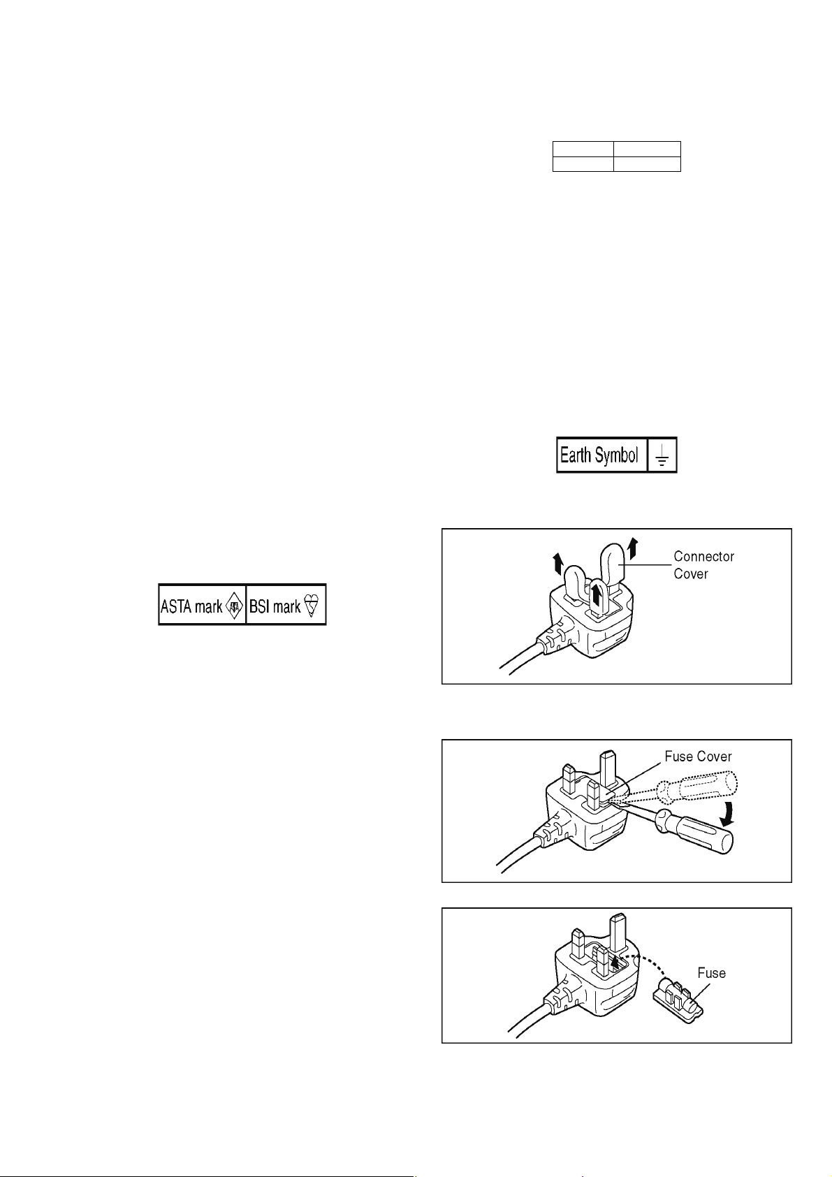
2.2.2. Caution for AC Mains Lead
For your safety, please read the following text carefully.
This appliance is supplied with a moulded three-pin mains plug
for your safety and convenience.
A 5-ampere fuse is fitted in this plug.
Should the fuse need to be replaced please ensure that the
replacement fuse has a rating of 5 amperes and it is approved
by ASTA or BSI to BS1362
Check for the ASTA mark or the BSI mark on the body of the
fuse.
2.2.2.1. Important
The wires in this mains lead are coloured in accordance with
the following code:
Blue Neutral
Brown Live
As the colours of the wires in the mains lead of this appliance
may not correspond with the coloured markings identifying the
terminals in your plug, proceed as follows:
The wire which is coloured BLUE must be connected to the terminal in the plug which is marked with the letter N or coloured
BLACK.
The wire which is coloured BROWN must be connected to the
terminal in the plug which is marked with the letter L or coloured
RED.
Under no circumstances should either of these wires be connected to the earth terminal of the three pin plug, marked with
the letter E or the Earth Symbol.
2.2.2.2. Before Use
Remove the Connector Cover as follows.
If the plug contains a removable fuse cover you must ensure
that it is refitted when the fuse is replaced.
If you lose the fuse cover, the plug must not be used until a
replacement cover is obtained.
A replacement fuse cover can be purchased from your local
Panasonic Dealer.
If the fitted moulded plug is unsuitable for the socket outlet in
your home then the fuse should be removed and the plug cut
off and disposed of safety.
There is a danger of severe electrical shock if the cut off plug is
inserted into any 13-ampere socket.
If a new plug is to be fitted please observe the wiring code as
shown below.
If in any doubt, please consult a qualified electrician.
2.2.2.3. How to Replace the Fuse
1. Remove the Fuse Cover with a screwdriver.
2. Replace the fuse and attach the Fuse cover.
5
Page 6
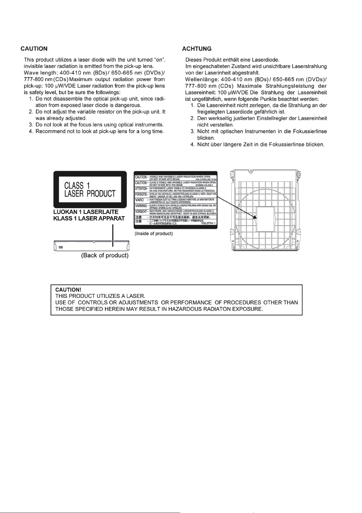
2.3. Precaution of Laser Diode
6
Page 7

2.4. General Description About Lead Free Solder (PbF)
The lead free solder has been used in the mounting process of all electrical components on the printed circuit boards used for this
equipment in considering the globally environmental conservation.
The normal solder is the alloy of tin (Sn) and lead (Pb). On the other hand, the lead free solder is the alloy mainly consists of tin
(Sn), silver (Ag) and Copper (Cu), and the melting point of the lead free solder is higher approx.30°C (86°F) more than that of the
normal solder.
Distinction of P.C.B. Lead Free Solder being used
Service caution for repair work using Lead Free Solder (PbF)
• The lead free solder has to be used when repairing the equipment for which the lead free solder is used.
(Definition: The letter of “PbF” is printed on the P.C.B. using the lead free solder.)
• To put lead free solder, it should be well molten and mixed with the original lead free solder.
• Remove the remaining lead free solder on the P.C.B. cleanly for soldering of the new IC.
• Since the melting point of the lead free solder is higher than that of the normal lead solder, it takes the longer time to melt the
lead free solder.
• Use the soldering iron (more than 70W) equipped with the temperature control after setting the temperature at 350±30°C
(662±86°F).
Recommended Lead Free Solder (Service Parts Route.)
• The following 3 types of lead free solder are available through the service parts route.
SVKZ000001-----------(0.3mm 100g Reel)
SVKZ000002-----------(0.6mm 100g Reel)
SVKZ000003-----------(1.0mm 100g Reel)
Note
* Ingredient: Tin (Sn) 96.5%, Silver (Ag) 3.0%, Copper (Cu) 0.5%. (Flux cored)
7
Page 8
2.5. Static Electricity Protection Measures
• The laser diode in the traverse unit (optical pick-up) may break down due to potential difference caused by static electricity of
clothes or human body.
So, be careful of electrostatic breakdown during repair of the traverse unit (optical pick-up).
2.6. Ground for electrostatic breakdown prevention
• As for parts that use optical pick-up (laser diode), the optical pick-up is destroyed by the static electricity of the working environment.
Repair in the working environment that is grounded.
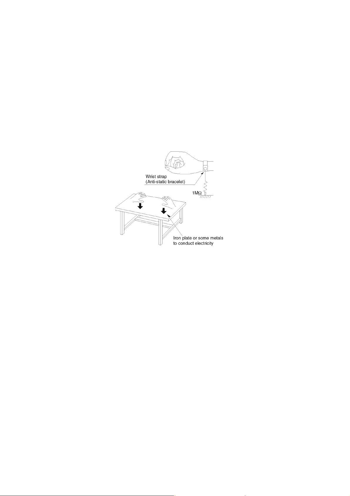
2.6.1. Work table grounding
• Put a conductive material (sheet) or steel sheet on the area where the traverse unit (optical pick-up) is placed, and ground the
sheet.
2.6.2. Human body grounding
• Use the anti-static wrist strap to discharge the static electricity from your body.
2.6.3. When exchange the BDP Drive
• Before remove the ESD prevention bag, make sure to use the anti-static wrist strap to discharge the static electricity when
replace the BDP Drive.
Note:
The ESD prevention bag is used to replace the original short-circuit point.
It can be removed while placing the BDP Drive.
8
Page 9
3 Service Navigation
3.1. Service Infomation
This service manual contains technical information which will allow service personnel’s to understand and service this model.
Please place orders using the parts list and not the drawing reference numbers.
If the circuit is changed or modified, this information will be followed by service manual to be filed with original service manual.
3.2. How to Update Firmware
The firmware of the unit may be renewed to improve the quality including operational performance and playability.
Make sure to refer the following procedure when performing version-up.
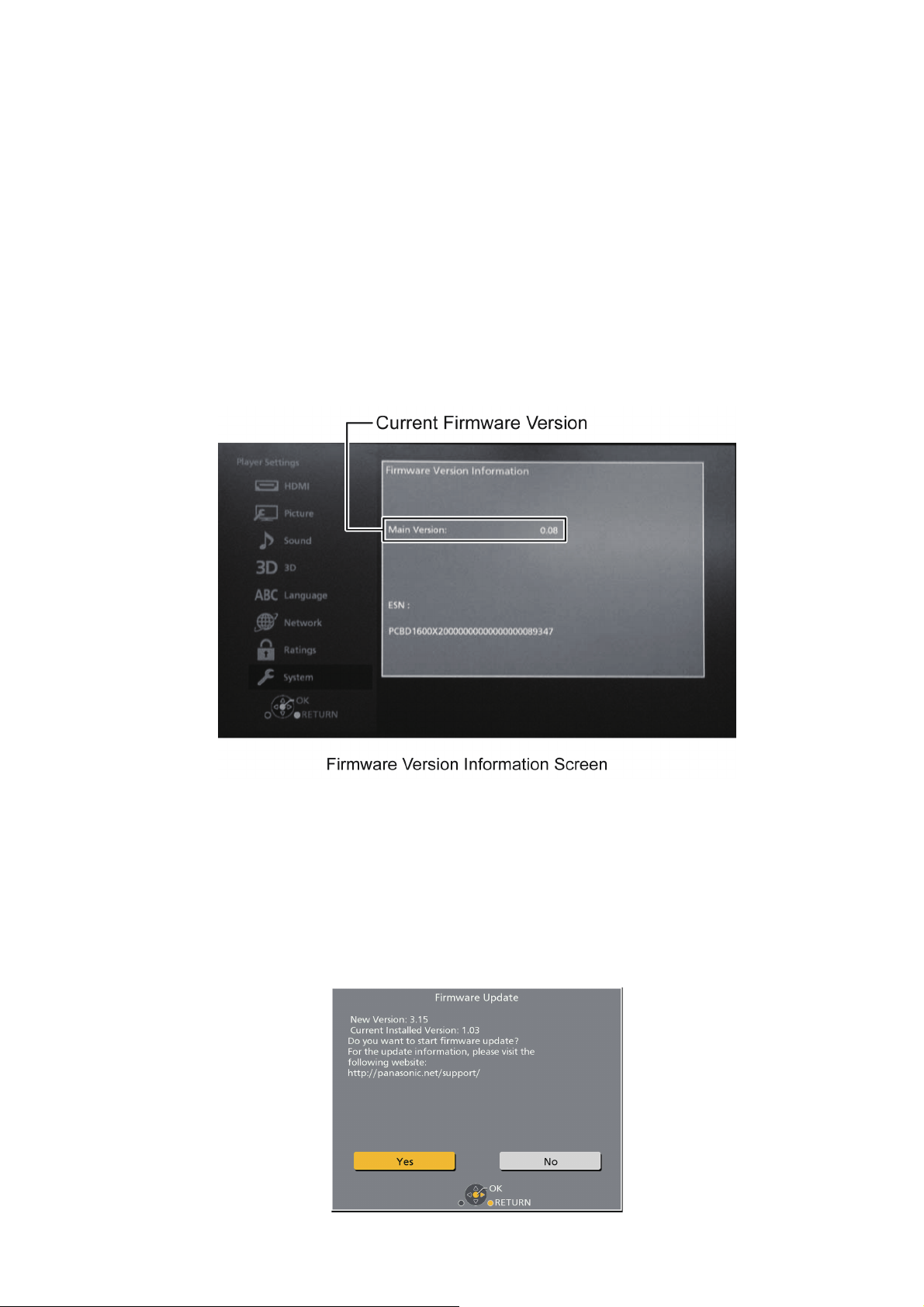
3.2.1. Confirmation of the Firmware Version
Perform following steps to checking the firmware version currently installed in the unit.
1. Turn the unit on and wait the Home screen is displayed.
2. Select [Setup] → [Player Settings] → [System] → [System Information] → [Firmware Version Information].
3. Firmware Version Information screen is displayed.
3.2.2. Updating Firmware
This unit has 2 updating method, one way to update via the internet, the other way to update using CD-R or USB device which is
stored pre-downloaded firmware update file.
3.2.2.1. Updating firmware via the internet
Occasionally, Panasonic may release updated
firmware for this unit that may add or improve the way a feature operates. These updates are available free of charge.
This unit is capable of checking the firmware automatically when connected to the Internet via a broadband connection.
When a new firmware version is available, the following message is displayed.
9
Page 10
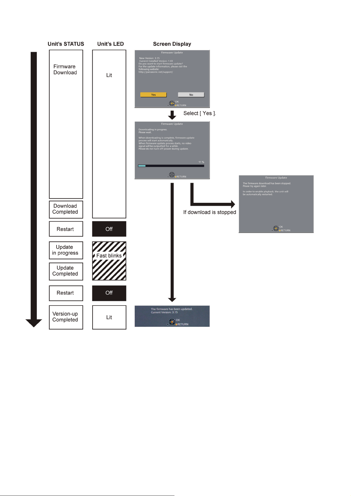
[ Update procedure]
DO NOT DISCONNECT the unit from the AC
power or perform any operation while the update takes place.
10
Page 11
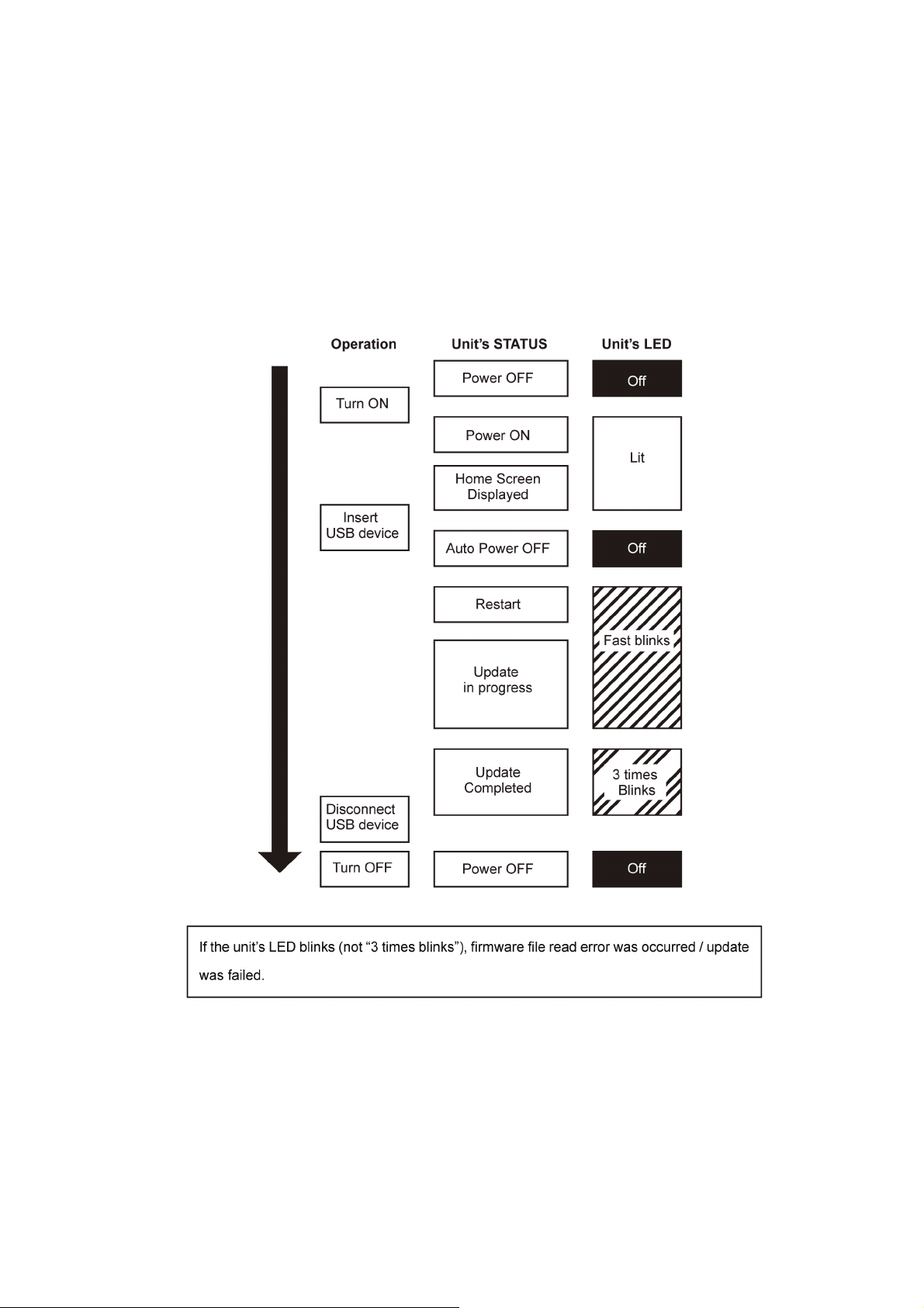
3.2.2.2. Updating firmware using the USB device
When updating firmware using USB device, perform following procedures.
(When using CD-R instead of USB device, perform same procedures)
1. Download the latest firmware file of the unit
The latest firmware required for version-up can be downloaded from TSN-Web site.
Click file name to download.
After download, click file to decompress.
2. Decompress the downloaded file
The decompressed file will be named as follows.
File Name: PANAEUSB.FRM
Copy the file to root folder of the USB device.
(If using CD-R instead of USB device, burn the file to a blank CD-R by writing software.)
3. Update the unit
Turn the unit on and home screen displayed, the firmware update is completed.
11
Page 12
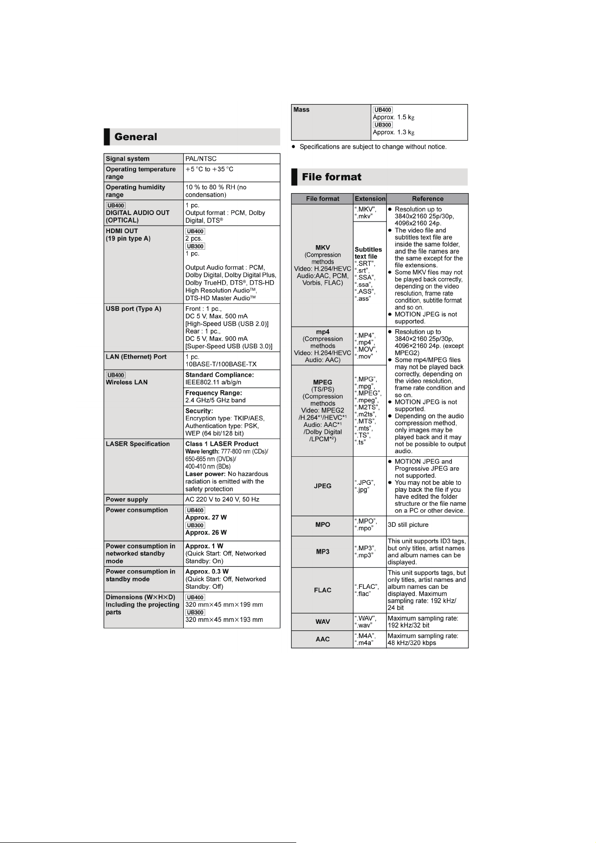
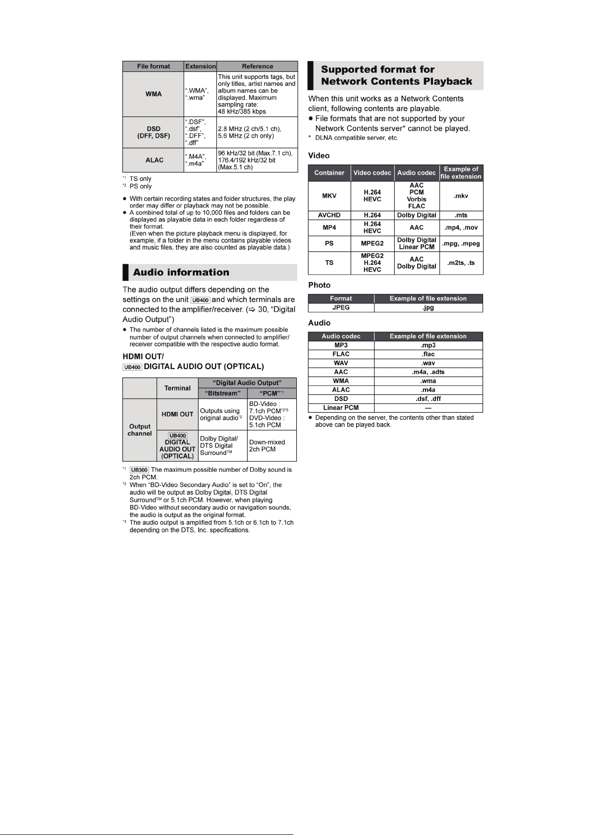
4 Specifications
The following specification is for DMP-UB400EB/UB300EB.
Some specifications may differ depending on model suffix.
12
Page 13
131415
Page 14
Page 15

4.1. Others (Licenses)
Page 16

5 Location of Controls and Components
The following specification is for DMP-UB400EB/UB300EB.
Some descriptions may differ depending on model suffix.
The page number in this chapter does not show the page number of this service manual.
16
Page 17

17
Page 18

6 Operating Instructions
6.1. Taking out the Disc from Drive Unit when the Disc cannot be ejected by OPEN/CLOSE button
6.1.1. Forcible Disc Eject
6.1.1.1. When the power can be turned off.
1. Turn the unit off, then press and hold [OK], [Yellow] and [Blue] buttons on the remote control simultaneously for 5 seconds.
- “00 RET” is displayed on the screen.
2. Repeatedly press the [ ] button on the remote control or [POWER] button on the unit until “06 FTO” is displayed on the
screen.
3. Press [OK] button on the remote control or [OPEN/CLOSE] button on the unit.
6.1.1.2. When the power can not be turned off.
Press [POWER] button on the unit for over 4 seconds to turn off the power forcibly, and step 1 to 3 above.
6.1.2. When the Forcible Disc Eject can not be done.
1. Turn off the power and pull out AC cord.
2. Remove the Top Case Ass’y.
3. Put the unit so that bottom can be seen.
4. Insert paper clips, etc. into the hole on the bottom of Drive Unit and slide the paper clips, etc. in the direction of the arrow to
eject tray slightly.
5. Put the unit upward, and pull out Tray by finger.
18
Page 19

6.2. Micro Fuse Conducting Check
This unit uses the Micro Fuse.
Check the Micro Fuse conducting using the Tester at the check points below.
19
Page 20

7 Service Mode
7.1. About the Multiple Pressing of the Unit’s Remote Control
The remote control which included this unit is possible pressing multiple buttons simultaneously (Multiple Pressing function), and
can operate for the customer's initial settings and the Service Mode, etc.
The Multiple Pressing function is not available for conventional models' remote control. Use the remote control included this unit.
7.2. How to enter the Special Modes using the Multiple Pressing Function of the Unit’s Remote Control
For pressing the multiple buttons of the remote control, this unit can be entering each of the following special modes.
After entering each mode, and then go to the menu you want to run.
• Move the menus for each mode:
Press [ ] button (Remote Cont.) or [POWER] button (Unit)
• Execute
Press [OK] button (Remote Cont.) or [OPEN/CLOSE] button (Unit)
* After executing the menu will automatically exit the special mode.
• How to exit from the special modes
• Press the unrelated buttons for the operation.
• No operation for 2 minutes or more.
• Press and hold [POWER] button on the unit. (Forcible Power Off)
20
Page 21

7.2.1. Open Mode (Remote Cont. Buttons: [OK] [Yellow] [Blue])
When pressing the 3 buttons, [OK], [Yellow] and [Blue] simultaneously for 5 seconds, “00 RET” is displayed on the screen.
21
Page 22

7.2.2. Privately Mode 1 (Remote Cont. Buttons: [6] [7] [Yellow])
When pressing the 3 buttons, [6], [7] and [Yellow] simultaneously for 5 seconds, “50 RET” is displayed on the screen.
7.2.3. Privately Mode 2 (Remote Cont. Buttons: [5] [9] [Red])
When pressing the 3 buttons, [5], [9] and [Red] simultaneously for 5 seconds, “70 RET” is displayed on the screen.
22
Page 23

7.3. About the Service Mode
Informations necessary for service can be displayed.
7.3.1. How to enter the Service Mode
7.3.2. How to exit the Service Mode
Press and hold the [POWER] button (remote control or unit).
>>> The Service Mode is terminated and automatically turns the unit off.
23
Page 24

7.4. Service Mode List
The display of information to each command is as follows.
Note:
Do not use it excluding the designated command.
24
Page 25

252627
Page 26

Page 27

7.5. Self-Diagnostics Functions
7.5.1. Self-Diagnostics Functions
Self-Diagnosis Function provides information for errors to service personnel by Self-Diagnosis Display when any error has
occurred.
U** and F** are stored in memory and held.
You can check last error code by transmitting [0] [1] in Service Mode.
Automatic Display on the screen will be cancelled when the power is turned off or AC input is turned off during self-diagnosis display
is ON.
Page 28

28
Page 29

8 Service Fixture & Tools
PartNo. Uses Pcs Compatibility
RFKZ0327 Extension Cable (Digital P.C.B. Unit - Main P.C.B. Unit / 15 Pin) 1 Same as DMP-BDT320 Series
SUKZ000007 Extension Cable (Digital P.C.B. Unit - Drive Unit / 18 Pin) 1 Same as DMP-UB900 Series
SVKZ000001 Lead Free Solder (0.3mm/100g Reel) Same as DMP-BDT320 Series
SVKZ000002 Lead Free Solder (0.6mm/100g Reel) Same as DMP-BDT320 Series
SVKZ000003 Lead Free Solder (1.0mm/100g Reel) Same as DMP-BDT320 Series
RFKZ0316 Solder Remover (Lead free Iow temperature Solder/50g) Same as DMP-BDT320 Series
RFKZ0328 Flux Same as DMP-BDT320 Series
*The above parts are supplied by HEBD.
29
Page 30

9 Disassembly and Assembly Instructions
9.1. Unit
9.1.1. Disassembly Flow Chart
The following chart is the procedure for disassembling the casing and inside parts for internal inspection when carrying out the servicing.
To assemble the unit, reverse the steps shown in the chart below.
9.1.2. P.C.B. Positions
30
Page 31

9.1.3. Top Case Ass’y
1. Remove the 3 screws (A).
2. Slide the Top Case Ass’y rearward (1) and open the both
ends at rear side of the Top Case Ass’y a little and lift the
Top Case Ass’y in the direction of arrow (2), then remove
the Top Case Ass’y.
2. Unlock 2 tabs turn.
Pull the Tray Ornament in the direction of arrow.
9.1.4. Front Panel Unit
1. Insert paper clips into the hole on the bottom of Dive Unit
through the hole of Chassis, and slide the lever in the
direction of arrow to eject tray slightly.
3. Disconnect the connector (P59303).
4. Unlock the 6 locking tabs turn, then remove the Front
Panel Unit in the direction of arrows.
31
Page 32

9.1.5. WLAN Module (UB310/UB314 only)
1. Remove the screw (A), then remove the WLAN Module.
9.1.6. DC Fan Motor
1. Remove the 2 screws (A).
2. Dosconnect the connector (P58804).
3. Remove the DC Fan Motor.
9.1.8. Drive Unit
1. Remove the FFC (connected to P58805).
2. Remove the 4 screws (A) to remove the Drive Unit.
9.1.8.1. Belt
1. Remove the 3 screws (A).
2. Unlock the 2 locking tabs.
9.1.7. Rear Panel
1. Remove the screw (A) and 2 screws (B).
2. (UB390 only) Remove the screw (C) .
3. Unlock 2 locking tabs to remove the Rear Panel in the
direction of arrow.
3. Lift up the Upper Base Ass’y in the direction of arrow (1),
and pull it out to the direction of arrow (2).
32
Page 33

4. Insert the Paper Clip into the hole of bottom side , and
slide it to the direction of arrow until it can be.
5. Pull ou the Tray to the direction of arrow.
9.1.9. Main P.C.B. Unit
1. Disconnect the connector (P58801).
2. Remove the screw (A) and 2 screws (B) to remove the
Main P.C.B. Unit.
6. Remove the Belt.
33
Page 34

9.1.10. Digital P.C.B. Unit
1. Disconnect the FFC ( connected to P58805).
2. Disconnect the connector (P58801).
3. Remove the 2 screws (A) to remove the Digital P.C.B.
Unit.
34
Page 35

9.2. Sticking position of Barrier Sheet
9.2.1. Barrier Sheet
• Stick Barrier Sheet on the Chassis.
35
Page 36

10 Measurements and Adjustments
For description of the disassembling procedure, see the “9 Disassembly and Assembly Instructions”.
10.1. Service Positions
10.1.1. Checking and repairing of Main P.C.B. Unit
36
Page 37

10.1.2. Checking and repairing of Drive Unit/Digital P.C.B. Unit
37
Page 38

10.2. Adjustment of Drive Unit
10.2.1. Repair Flowchart
10.2.2. Adjustment
This unit does not have the necessity for adjustment after replacing the Drive Unit.
38
Page 39

10.3. Caution for Replacing Parts
After replacing the Digital P.C.B. Unit, [TEST] is displayed, so, once power off again to on.
10.3.1. Caution after replacing parts
After replacing the Drive Unit/Digital P.C.B. Unit, must be update Firmware.
Please see the Chapter 3.2. How to Update Firmware.
10.3.2. Standard Inspect Specifications after Repairs
After making repairs, we recommend performing the following inspection, to check normal operation.
39
Page 40

11 Block Diagram
DDR3
4G-bit x1
DDR3
2G-bit x2
DDR3
2G-bit x 2
MAIN MICROCOMPUTER
(PXS2)
TIMER MICROCOMPUTER
DIGITAL P.C.B. UNIT
BD/DVD DRIVE
MAIN P.C.B. UNIT
Wi-Fi MODULE
SW REGULATOR
REAR PANEL
DIGITAL OUTPUT
AV OUTPUT
NETWORK/GENERAL-PURPOSE IF
HDMI
VIDEO/AUDIO
OUTPUT
OPTICAL
AUDIO
OUTPUT
EACH VOLTAGE
REGULATOR
NICAESUF
USB 2.0
USB TERMINAL
COOLING
FAN
HDMI
AUDIO
OUTPUT
DMP-UB300EG/EB
DMP-UB310EG
DMP-UB314EG
DMP-UB390EB
OVERALL BLOCK DIAGRAM
LED
REMOTE
SENSOR
KEY
FRONT PANEL
NAND FLASH
ROM/4G-bit
ETHERNET
CONTROLLER
USB 3.0
USB
TERMINAL
ETHERNET
(LAN TERMINAL)
USB0
(3.0)
USB3
(2.0)
USB1
(3.0)
(UHD BD)
SATA
DMP-UB310EG
DMP-UB314EG
ONLY
DMP-UB390EB
ONLY
11.1. Overall Block Diagram
40
Page 41

11.2. Power Supply Circuit Block Diagram
F11101
10111L10111P
D11102
C11301
Q11301
MAIN
SW
DRIVER
T11301
D13201
D13202
C13201
C13202
C13203
PW_X_SW12R0V
10231L
AC_INLET
FUSE
LINE FILTER
RECTIFYING
CIRCUIT
8
3
6
IC11301
ON/OFF
CONTROL
1 5 4
2
MAIN SW
GATE CONTROL
STANDBY
CONTROL
Q12201
IC12202
PHOTO
COUPLER
SHUNT
REGULATOR
IC
OUTPUT VOLTAGE
FEED BACK
OVERCURRENT
DETECTION
Z/C DETECTION
GATE ON TRIGGER
12,13,14,15
P58801P6702
TO
DIGITAL P.C.B.
UNIT
REGULATOR
BLOCK SECTION
DMP-UB300EG/EB
DMP-UB310EG
DMP-UB314EG
DMP-UB390EB
POWER SUPPLY CIRCUIT BLOCK DIAGRAM
C11105
41
Page 42

PW_X_SW12R0V
12,13,14,15
P58801P6702
FROM
MAIN P.C.B. UNIT
IC58401
DR_5V
(REG. 5V)
3
5
2
DR_12V
VIN
EN
SW
HDD_PFAIL_L
(RESET)
IC58402
VDD
2
OUT
1
DR_P_ON_H
IC59501-
41
DR_P_ON_H
IC59501-
41
IC59501-
38
TO BD DRIVE
Q58401
QR58401
IP58401
2 1
IC58202
(REG. 3.3V)
3
7
VCC
SW
EN
4
PG
IP58202
2 1
2
PXS2_PFAIL_1
IC59501-
16
IC58201
(REG. 1.8V)
3
7
VCC SW
VCC SW
VCC SW
EN
4
PG
IP58201
2 1
2
PXS2_PFAIL_1
IC59501-
16
IC58101
(REG. 1.5V)
3
7
EN
6
PG
IP58101
2 1
2
PXS2_PFAIL_1
IC59501-
16
AW_0R9V_PFAIL
IC59501-
5
IC58001
(REG. 0.9V)
5
4
OUT_H
EN
7
OUT_L
IP58001
2 1
9
LX
8
VIN
IC58002
(REG. 0.9V)
3
7
EN
IP58002
2 1
2
IP58803
2 1
IP58802
2 1
HDMI_P_ON_H
HDMI_P_ON_H
PW_HDMI1_5V
JK55301, IC55301
IC58602
(REG. 5V)
3
6
EN
VO
IC59501-
37
67
1VI
PW_HDMI2_5V
PW_AUSW5R1V
JK55302, IC55302
IC58604
(REG. 5V)
3
6
EN
VO
IC59501-
37
1VI
IC58501
(REG. 5.1V)
3
5
2
VIN
EN
SW
IP58502
2 1
IP59501
2 1
W LAN SW ON H
PW_5V_VBUS_1
PW_DRIVE_5V
PW_DR_11R9V
Wi-Fi MODULE
IC58704
(REG. 5V)
3
6
EN
VO
IC59501-
1VI
PXS2_USB3VBUS
PXS2_PW_5V_VBUS_3
P58801
IC58901
(REG. 5V)
3
6
EN
VO
4
FLG
IC51001-
B36
PXS2_USB3OD
IC51001-
A37
1VI
PXS2_USB0VBUS
PXS2_PW_5V_VBUS_0
JK59001
IC58702
(REG. 5V)
3
6
EN
VO
4
FLG
IC51001-
N34
PXS2_USB0OD
IC51001-
K37
1VI
4
P59303
3,4,5
P58805
TO BD DRIVE
9,10,11
P58805
JK54003
IC59505
PW_PXS2_AW1R8V
(REG. 1.8V)
IC58304
ON
1
VIN
3
VOUT
4
IC51001,IC59506
PW_X_SW3R8V
IC59510
PW_X_SW3R3V
IC59501
PW_PXS2_M0R9V
IC51001
PW_PXS2_C0R9V
IC51001
PW_PXS2_D1R5V
PW_X_SW12R0V
IC59504
PW_X_SW12R0V
IC51001,IC52000,IC52001
IC52202,IC52203,IC52403
PW_PXS2_D1R8V
IC51001,IC51301,IC55301, IC55302
PW_PXS2_D3R3V
IC51001,IC59501
IC59501-
35
PW_EH_1R8V
(REG. 1.8V)
IC58305
ON
1
VIN
3
VOUT
4
IC59001
PXS2_ON_H
IC59501-
26
PXS2_ON_H
PXS2_AW_ON_H
IC59501-
26
EH_ON_H
IC59501-
65
PXS2_ON_H
IC59501-
26
Q58007
G
D
S
Q58008
G
D
S
OUT SIDE
Q58003,
Q58006
D3.3V OUT
Q58001,
Q58004
DELAY
Q58002,
Q58005
DMP-UB300EG/EB
DMP-UB310EG
DMP-UB314EG
DMP-UB390EB
DIGITAL P.C.B. UNIT REGULATOR CIRCUIT BLOCK DIAGRAM
(REG. 3.3V)
IC59503
ON
1
VIN
4
VOUT
3
(REG. 3.8V)
IC59507
ON
1
VIN
4
VOUT
3
PW_PXS2_AW0R9V
(REG. 0.9V)
IC58303
ON
1
VIN
4
VOUT
3
IC51001
PW_PXS2_A2R3V
(REG. 2.3V)
IC58302
ON
1
VIN
4
VOUT
3
IC51001
PW_EH_3R3V
(REG. 3.3V)
IC58306
ON
1
VIN
4
VOUT
3
IC59001
DMP-UB310EG
DMP-UB314EG
ONLY
DMP-UB390EB
ONLY
DMP-UB390EB
ONLY
11.3. Digital P.C.B. Unit Regulator Circuit Block Diagram
42
Page 43

PW_X_SW3R3V
(RESET)
IC59505
OUT VDD PW_X_SW12R0V
PW_DR_11R9V
P FAIL[L]
32.768KHz OUT
32.768KHz IN
32.768KHz
X59502
IC59501
(TIMER)
REMOCON
DIGITAL P.C.B. UNIT
MAIN P.C.B. UNIT
G_REMOCON
REMOCON
KEY2(EJECT)
KEY1(POWER)
POWER LEDLED_POWER
KEY_PWR
KEY_OP_CL
P7201P58801
7
P67201P58801
6
P7201P58801
9
VDD(3.3)
17
12
31
13
11
2132
(RESET)
IC58402
OUT VDD
HDD_PFAIL[L]
2138
OUT VDD
21
IC59502
(RESET)
RESET
KEYIN3(POWER)
KEYIN1(OP/CL)
IR7401
SENSOR
REMOTE CTL.
1
PW_XSW_3R3V
PW_XSW_3R3V
2
IC51001
TIMER I/F
(PXS2)
TRY_DIRECT
46
P58805
1
1
WOW INT
56
P59303
5
TRY_OP_CL
47
P58805
2
TO/FROM
BD DRIVE
FROM
Wi-Fi MODULE
FANLOCK
FAN_LOCK
FAN_PWR
36
HDMI_P_ON[H]
HDMI_P_ON_H
37
DR_P_ON_H
41
DR_P_ON_H
PXS2_AW_ON_H
35
76
26
PXS2_ON_H
PXS2_AW_ON_H
FAN_DA
PXS2_ON_H
REGULATOR
BLOCK SECTION
TO/FROM
DIGITAL P.C.B.
PX2_PFAIL_L
0.9V_PFAIL_AW(AD)
PX2_PFAIL_1
16
28
7
SOC_INTTIM
SOC_INTSOC
SOC_SOCREQ
UART_TXD
UART_RXD
XRES_PXS2
PXS2_XRST
PXS2_O_STATE
G_PXS2_TXD3_B
G_PXS2_RXD3_B
G_TM_TIMREQ_B
G_TM_SOCREQ_B
G_TM_INTSOC_B
G_TM_INTTIM_B
48
57
58
BUFFER
QR51301,
QR51302
XRST
AI2D2
XIRQ20
AI2D3
XIRQ19
PORT225
PORT224
AV25
66
SD USB BOOT
PXS2_LPST
BUFFER
QR51309,
QR51306
LPST
AN21
52
PXS2 LPCTL
PXS2_LPCTL
BUFFER
QR51312,
QR51311
LPCTL
AM21
25
NC(OPEN)
SEL_DEV_WOL
BUFFER
QR59003,
QR59004
PORT284
AM25
27
NC(OPEN)
PXS2_WL_ON_H
BUFFER
QR59005,
QR59006
PORT285
AT25
PXS2_STATE
34
59
WOL INT
71
50
AI2D1
AD3
AE5
AD36
AD4
SOC_TIMREQ
AE37
AH33
AJ32
(RESET)
IC59506
OUTVDD
PW_PXS2_AW1R8V
1
2
(ETHER CONTROLLER)
IC59001
LED
30
PW_PXS2_AW0R9V
5
0.9V_PFAIL_M(AD)
3
PW_PXS2_M0R9V
M
FAN MOTOR
PW_X_SW12R0V
(FAN MOTOR DRIVE)
A OUT
1
8
A-IN
2
P58804
P58804
1
3
A+IN
V+
3
42
FAN_P_ON_H
IC59504
Q59508
DMP-UB300EG/EB
DMP-UB310EG
DMP-UB314EG
DMP-UB390EB
TIMER CIRCUIT BLOCK DIAGRAM
POWER
S7201
P7201P58801
5
OPEN/CLOSE
S7202
D7501
POWER
LED
49
51
55
69
LED_POWER
LED_PWM/256Hz
QR59503
QR59504
QR59007
0.9V_PFAIL_C(AD)
2
IP59501
2 1
PW_EH_3R3V
PW_EH_1R8V
DMP-UB310EG
DMP-UB314EG
ONLY
11.4. Timer Circuit Block Diagram
43
Page 44

11.5. Digital Circuit Block Diagram
AO2IEC
VIDEO PB SIGNAL
AUDIO PB SIGNAL
D11
MM1CK
C11
D27
AE3
E27
MM1XCK
MM1XCK
MM1CK
MM1XCK
MM1CK
/CK
IC52202
(2GBIT DDR3 SDRAM FOR PEAKS-PRO_CH1)
K7
J7
K7
J7
MM1DQ0-15, MM1A0-13
CK
/CKK7
J7 CK
IC52203
(2GBIT DDR3 SDRAM FOR PEAKS-PRO_CH1)
/CK
CK
MM1DQ16-31, M1A0-13
MM1DQ0-15, MM1A0-13
MM1DQ16-31, MM1A0-13
IC52403
(4GBIT DDR3 SDRAM FOR PEAKS-PRO_CH2)
MM1CK
MM1XCK
DDR3_CH1_IF
N4
MM0CK
N3
MM0XCK
MM0XCK
MM0CK
MM0XCK
MM0CK
/CK
IC52000
(2GBIT DDR3 SDRAM FOR PEAKS-PRO_CH0)
K7
J7
K7
J7
MM0DQ0-15, MM0A0-13
CK
IC52001
(2GBIT DDR3 SDRAM FOR PEAKS-PRO_CH0)
/CK
CK
MM0DQ16-31, MM0A0-13
MM0DQ0-15, MM0A0-15
MM0DQ16-31, MM0A0-13
MM0CK
MM0XCK
DDR3_CH0_IF
MM2CK
MM2XCK
MM2XCK
MM2CK
MM2DQ0-15, MM2A0-13MM2DQ0-15, MM2A0-13
MM2CK
MM2XCK
DDR3_CH2_IF
7
6
5
4
24
IC51301
NAND FLASH
ROM/4GB
BUS_NFD0-7_B
HOST
IF
(LAN/USB 3.0 PORT)
JK59001
P7406
(USB 2.0/FRONT)
2
3
IC59001
(ETHER CONTROLLER)
TXP
TXN
RXP
RXN
TDP
TDN
4
5
2
3
RDP
RDN
DN
DP
USB3DN
USB3DP
AR9
TXD0
32
19
16
AU2
RST#
AV3
REFCLK
AU4
RXD0
21
AT1
INTRP
RGMII_TXD0
25
AT9
TXD1
RGMII_TXD1
PHYRSTL
RGMII_RXCLK
18
AT6
CRSDV
RGMII_RXCTL
23
AR8
TXEN
RGMII_TXEN
RGMII_RXD0
15
AV5
RXD1
RGMII_RXD1
20
AT5
RXER
RGMII_RXER
MDIO_INTL
11
AU1
MDIO
MDIO
12
AR1
MDC
MDC
A35
A36
IC51001_PXS2
(HD DEC/ ENC/ CPU/ GFX PROSESSOR/DDR3-IF/RTSC/AV CORE/GRAPHICS)
P58805
BD/DVD
DRIVE
17
16
14
13
FI_EDI
SATA_RXP
SATA_RXN
SATA_TXN
SATA_TXP
SATARXP
SATARXM
SATATXM
SATATXP
C33
D33
C31
D31
L56002
L56001
T59301
L59303
IC55301
(LEVEL SHIFT)
SCL1
SDA1
SCL2
SDA2
6
5
3
4
IC59510
(CEC 1chip)
CONT
TIMER
CEC
4
2
3
XI
9
XO
8
19
18
16
15
13
12
SOC_INTTIM
SOC_INTSOC
SOC_SOCREQ
UART_TXD
UART_RXD
48
34
50
58
59
HDMI_MONI
(CEC IN)
HDMI_CEC_OUT
HDMI_CONT
HDMI_MONI
DIRECT
OPEN/CLOSE
BUFFER
Q55305,
Q55306
TRY_DIRECT
TRY_OP/CL
IC59501
(TIMER)
BD/DVD
DRIVE
AI2D2
XIRQ20
AI2D3
XIRQ19
PORT225
PORT224
1
P58805
2
46
47
33
39
AT24
AN22
AM22
AT20
AR20
AT21
AR21
AP21
AR22
AP23
AR23
PXS2_STATE
7
AI2D1
AD3
AE5
AD36
AD4
SOC_TIMREQ
57
AE37
AH33
AJ32
Wi-Fi
MODULE
P59303
USB1DN
USB1DP
C37
D36
2
3
L55301
L55302
JK55301
1
3
4
6
7
9
10
12
D2+
D2D1+
D1D0+
D0CLK+
CLK-
16
15
HDMISDA
HDMISCL
HOTPLG
HDMI JACK
(MAIN)
13 CEC
19
T0HPD
HTDDCSCL0
HTDDCSDA0
T0D3N
T0D3P
T0D2N
T0D2P
T0D1N
T0D1P
T0D0N
T0D0P
JK54003
OPTICAL
(DIGITAL AUDIO OUT)
1
DIGITAL P.C.B. UNIT
X51203
(25MHz)
AXO
AXI
X59001
(25MHz)
IC55302
(LEVEL SHIFT)
SCL1
SDA1
SCL2
SDA2
6
5
3
4
BUFFER
Q55301,
Q55302
AP24
AN23
AP22
AT15
AR15
AT16
AR16
AP17
AR16
AP18
AR18
L55303
L55304
JK55302
1
3
4
6
7
9
10
12
D2+
D2D1+
D1D0+
D0CLK+
CLK-
16
15
HDMISDA
HDMISCL
HOTPLG
HDMI JACK
(SUB)
19
T1HPD
HTDDCSCL1
HTDDCSDA1
T1D3N
T1D3P
T1D2N
T1D2P
T1D1N
T1D1P
T1D0N
T1D0P
L35
M35
L35
K35
L34
M34
USB0TXP
USB0TXN
USB0RXP
USB0RXN
USB0DP
USB0DN
AV24
AU24
DMP-UB300EG/EB
DMP-UB310EG
DMP-UB314EG
DMP-UB390EB
DIGITAL CIRCUIT BLOCK DIAGRAM
DMP-UB310EG
DMP-UB314EG
ONLY
DMP-UB390EB
ONLY
DMP-UB390EB
ONLY
44
Page 45

12 Wiring Connection Diagram
DRIVE UNIT
MAIN P.C.B. UNIT DIGITAL P.C.B. UNIT
DMP-UB300EG/EB
DMP-UB310EG
DMP-UB314EG
DMP-UB390EB
INTERCONNECTION DIAGRAM
DMP-UB310EG
DMP-UB314EG
ONLY
WIFI MODULE
FAN
1
2
3
4
5
6
7
8
9
10
11
12
13
14
15
1
2
3
4
5
6
7
8
9
10
11
12
13
14
15
USB3_DM
USB3_DP
PW_5V_VBUS3
GND
KEY2(EJECT)
REMOCON
POWER_LED
PW_X_SW3R3V
KEY1(POWER)
GND
GND
PW_XSW12R0V
PW_XSW12R0V
PW_XSW12R0V
PW_XSW12R0V
1
2
3
4
5
GND
USB1 DP
USB1 DN
PW_5V_VBUS_1
WLAN_WOL
FAN PWR
FAN GND
FAN LOCK
1
2
3
USB3_DM
USB3_DP
PW_5V_VBUS3
GND
KEY2(EJECT)
REMOCON
POWER_LED
PW_X_SW3R3V
KEY1(POWER)
GND
GND
PW_X_SW12R0V
PW_X_SW12R0V
PW_X_SW12R0V
PW_X_SW12R0V
LNLIVE
NEUTRAL
P58801P6702
1
2
3
4
5
6
7
8
9
10
11
12
13
14
15
16
17
18
DIRECT
OPEN/CLOSE
DR_5V
DR_5V
DR_5V
DRGND
DRGND
DRGND
DR_12V
DR_12V
DR_12V
GND
SATA BDTXP
SATA BDTXN
GND
SATA BDRXN
SATA BDRXP
GND
P11101
P58805
P58804
P59303
12.1. Interconnection Diagram
45
Page 46

13 Schematic Diagram
Please click the radio button for "Diagrams II / Parts List" on the menu bar in XML Service Manual.
If you want to print, please click the icon button for "Print" on the icon bar and select the item.
14 Printed Circuit Board
Please click the radio button for "Diagrams II / Parts List" on the menu bar in XML Service Manual.
If you want to print, please click the icon button for "Print" on the icon bar and select the item.
15 Exploded View and Replacement Parts List
Please click the radio button for "Diagrams II / Parts List" on the menu bar in XML Service Manual.
If you want to print, please click the icon button for "Print" on the icon bar and select the item.
46
 Loading...