

Page 1
Digital Camera/Lens Kit
DMC-L1KPP
DMC-L1KEB
DMC-L1KEG
DMC-L1KGC
DMC-L1KGK
DMC-L1KGN
DMC-L1KGT
ORDER NO. DSC0608017CE
B26
Vol. 1
Colour
(K)...........Black Type
© 2006 Matsushita Electric Industrial Co., Ltd. All
rights reserved. Unauthorized copying and
distribution is a violation of law.
Page 2
DMC-L1KPP / DMC- L1KEB / DMC- L1KEG / DMC-L1KGC / DMC-L1KGK / DMC-L1KG N / DMC-L1KGT
CONTENTS
Page Page
1 INTRODUCTION 3
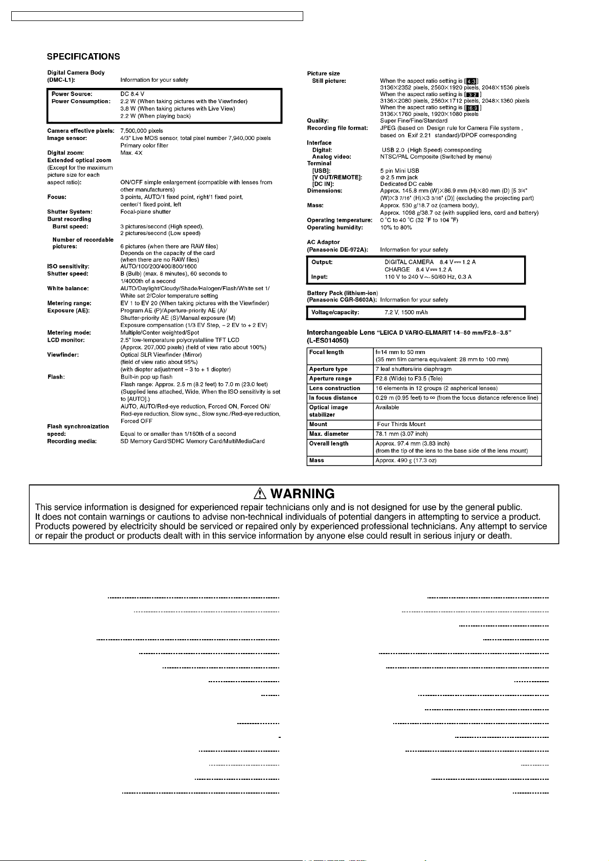
1.1. INTRODUCTION
1.2. HOW TO DEFINE THE MODEL SUFFIX (NTSC or PAL
model)
2 SAFETY PRECAUTIONS
2.1. GENERAL GUIDELINES
2.2. LEAKAGE CURRENT COLD CHECK
2.3. LEAKAGE CURRENT HOT CHECK (See Figure 1.)
3 PREVENTION OF ELECTRO STATIC DISCHARGE (ESD) TO
ELECTROSTATICALLY SENSITIVE (ES) DEVICES
4 HOW TO RECYCLE THE LITHIUM ION BATTERY(U.S. ONLY)
5 CAUTION FOR AC CORD (EB/GC only)
5.1. INFORMATION FOR YOUR SAFETY
5.2. CAUTION FOR AC MAINS LEAD
6 OPERATING GUIDE
7 OPERATING INFORMATION
8 TROUBLESHOOTING
3
9 ERROR CODE MEMORY FUNCTION
3
10 CONFIRMATION OF FIRMWARE VERSION
11 MAINTENANCE
6
6
12 SERVICE NOTES
6
6
7
7
8
8
8
9
12.1. ABOUT THE LENS (Being Supplied as a KIT)
12.2. ABOUT THE BODY
13 DISASSEMBLY/ASSEMBLY
14 EXPLODED VIEWS
14.1. FRAME & CASING SECTION
14.2. LENS SECTION
14.3. PACKING PARTS & ACCESSORIES SECTION
15 REPLACEMENT PARTS LIST
15.1. MECHANICAL REPLACEMENT PARTS LIST
2
10
14
18
20
21
23
23
23
24
25
25
26
27
28
28
Page 3
DMC-L1KPP / DMC- L1KEB / DMC- L1KEG / DMC-L1KGC / DMC-L1KGK / DMC-L1KG N / DMC-L1KGT
1 INTRODUCTION
1.1. INTRODUCTION
This service manual contains technical information, which allow service personnel’s to understand and service this model.
Please place orders using the parts list and not the drawing reference numbers.
If the circuit is changed or modified, the information will be followed by service manual to be controlled with original service manual.
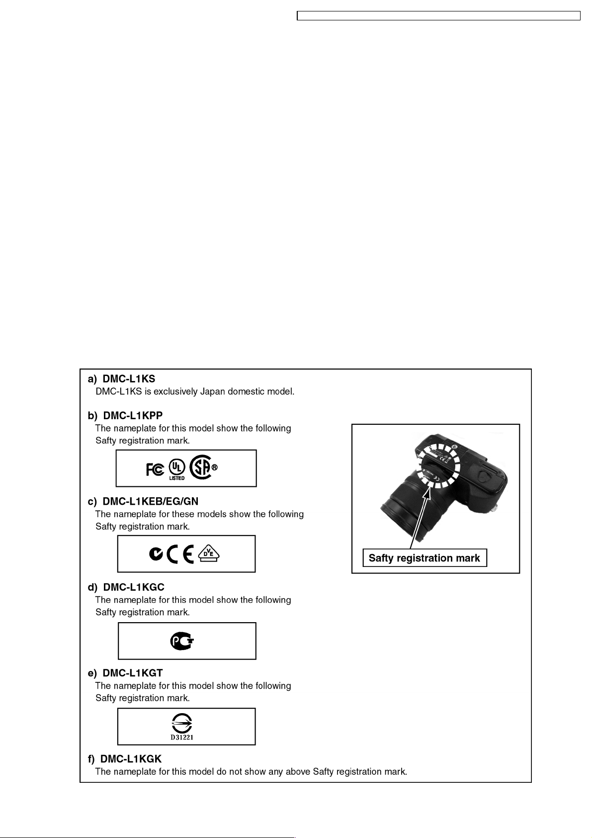
1.2. HOW TO DEFINE THE MODEL SUFFIX (NTSC or PAL model)
There are six kinds of DMC-L1K, regardless of the colours.
·a) DMC-L1KS
·b) DMC-L1KPP
·c) DMC-L1KEB/EG/GN
·d) DMC-L1KGC
·e) DMC-L1KGT
·f) DMC-L1KGK
(DMC-L1KS is exclusively Japan domestic model.)
What is the difference is that the “INITIAL SETTIN G” data which is stored in Flash ROM mounted on Main PCB.
1.2.1. Defining methods:
To define the model suffix to be serviced, refer to the nameplate which is putted on the bottom side of the Unit.
3
Page 4
DMC-L1KPP / DMC- L1KEB / DMC- L1KEG / DMC-L1KGC / DMC-L1KGK / DMC-L1KG N / DMC-L1KGT
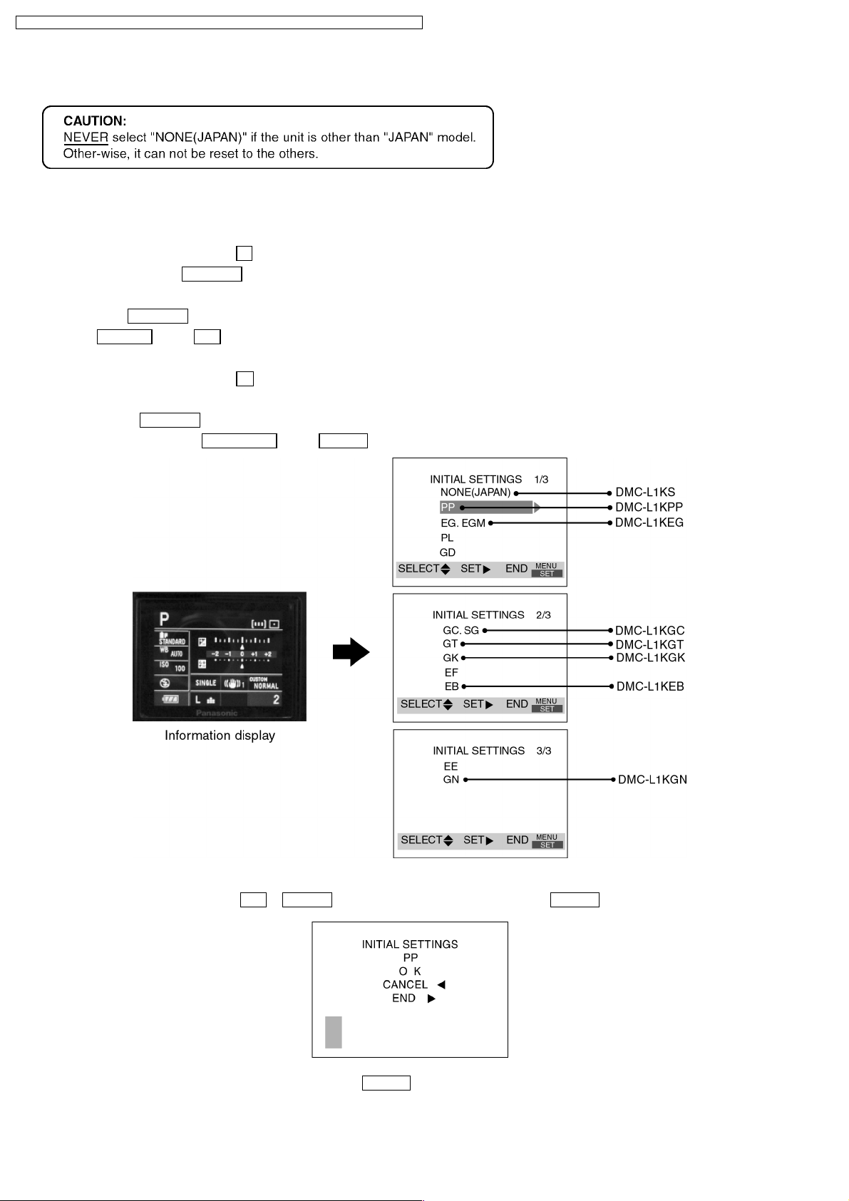
1.2.2. INITIAL SETTINGS:
When you replace the Main PCB be sure to perform the initial settings after achieving the Adjustment, by ordering the following
procedure in accordance with model suffix.
·Step 1. The temporary cancellation of factory setting:
Set the shutter speed dial to “ 8
While keep pressing AFL/AEL
·Step 2. The cancellation of factory setting:
Press the “ Playback
Press FUNC.2
” button to playback mode.
and “ UP of Cursor key” simultaneously, then turn the Power off.
·Step 3. Turn the Power on:
Set the shutter speed dial to “ A
·Step 4. Display the INITIAL SETTING:
1. Press the Playback
button, and then viewing information display.
2. While keep pressing MENU/SET
”.
, then turn the Power on.
”, and then turn the Power on.
and “ RIGHT of Cursor key” simultaneously, turn the Power off.
·Step 5. Set the INITIAL SETTING:
Select the area with pressing “ UP
/ DOWN of Cursor key”, and then press the “ RIGHT of Cursor key”.
The only set area is displayed, and then press the “ RIGHT of Cursor key” after confirmation.
(The unit is powered off automatically.)
4
Page 5

DMC-L1KPP / DMC- L1KEB / DMC- L1KEG / DMC-L1KGC / DMC-L1KGK / DMC-L1KG N / DMC-L1KGT
Confirm the display of “PLEASE SET THE CLOCK” in English when the unit is turned on again.
·Step 6. CONFIRMATION:
The display shows “PLEASE SET THE CLOCK” when turn the Power on again.
When the unit is connected to PC with USB cable, it is detected as removable media.
(When the “GT” or “GK” model suffix is selected, the display shows “PLEASE SET THE CLOCK” in Chinese.)
1) As for your reference Default setting condition is given in the following table.
·Default setting (After “INITIAL SETTINGS”)
MODEL VIDEO OUTPUT LANGUAGE DATE REMARKS
a) DMC-L1KS NTSC Japanese Year/Month/Date
b) DMC-L1KPP NTSC English Month/Date/Year
c) DMC-L1KEB/EG/GC/GN PAL English Date/Month/Year
d) DMC-L1KGK PAL Chinese (simplified) Year/Month/Date
e) DMC-L1KGT NTSC Chinese (traditional) Year/Month/Date
5
Page 6
DMC-L1KPP / DMC- L1KEB / DMC- L1KEG / DMC-L1KGC / DMC-L1KGK / DMC-L1KG N / DMC-L1KGT
2 SAFETY PRECAUTIONS
2.1. GENERAL GUIDELINES
1. IMPORTANT SAFETY NOTICE
There are special components used in this equipment
which are important for safety. These parts are marked by
in the Schematic Diagrams, Circuit Board Layout,
Exploded Views and Replacement Parts List. It is essential
that these critical parts should be replaced with
manufacturer’s specified parts to prevent X-RADIATION,
shock, fire, or other hazards. Do not modify the original
design without permission of manufa cturer.
2. An Isolation Transformer should always be used during the
servicing of AC Adaptor whose chassis is not isolated from
the AC power line. Use a transformer of adequate power
rating as this protects the technician from accidents
resulting in personal injury from electrical shocks. It will also
protect AC Adaptor from being damaged by accidental
shorting that may occur during servicing.
3. When servicing, observe the original lead dress. If a short
circuit is found, replace all parts which have been
overheated or damaged by the short circuit.
4. After servicing, see to it that all the protective devices such
as insulation barriers, insulation papers shields are properly
installed.
5. After servicing, make the following leakage current checks
to prevent the customer from being exposed to shock
hazards.
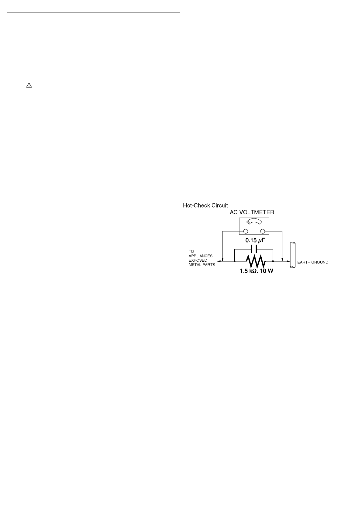
2.3. LEAKAGE CURRENT HOT
CHECK (See Figure 1.)
1. Plug the AC cord directly into the AC outlet. Do not use an
isolation transformer for this check.
2. Connect a 1.5 k:, 10 W resistor, in parallel with a 0.15 µF
capacitor, between each exposed metallic part on the set
and a good earth ground, as shown in Figure 1.
3. Use an AC voltmeter, with 1 k:/V or more sensitivity, to
measure the potential across the resistor.
4. Check each exposed metallic part, and measure the
voltage at each point.
5. Reverse the AC plug in the AC outlet and repeat each of the
above measurement s.
6. The potential at any point should not exceed 0.75 V RMS.
A leakage current tester (Simpson Model 229 or equivalent)
may be used to make the hot checks, leakage current must
not exceed 1/2 mA. In case a measurement is outside of
the limits specified, there is a possibility of a shock hazard,
and the equipment should be repaired and rechecked
before it is returned to the customer.
2.2. LEAKAGE CURRENT COLD
CHECK
1. Unplug the AC cord and connect a jumper between the two
prongs on the plug.
2. Measure the resistance value, with an ohmmeter, between
the jumpered AC plug and each exposed metallic cabinet
part on the equipment such as screwheads, connectors,
control shafts, etc. When the exposed metallic part has a
return path to the chassis, the reading should be between 1
M: and 5.2 M:. When the exposed metal does not have a
return path to the chassis, the reading must be infinity.
Figure. 1
6
Page 7

DMC-L1KPP / DMC- L1KEB / DMC- L1KEG / DMC-L1KGC / DMC-L1KGK / DMC-L1KG N / DMC-L1KGT
3 PREVENTION OF ELECTRO STATIC DISCHARGE (ESD)
TO ELECTROSTATICALLY SENSITIVE (ES) DEVICES
Some semiconductor (solid state) devices can be damaged easily by static electricity. Such components commonly are called
Electrostatically Sensitive (ES) Devices.
The following techniques should be used to help reduce the incidence of component damage caused by electro static discharge
(ESD).
1. Immediately before handling any semiconductor component or semiconductor-equipped assembly, drain off any ESD on your
body by touching a known earth ground. Alternatively, obtain and wear a commercially available discharging ESD wrist strap,
which should be removed for potential shock reasons prior to applying power to the unit under test.
2. After removing an electrical assembly equipped with ES devices, place the assembly on a conductive surface such as
aluminum foil, to prevent electrostatic charge buildup or exposure of the assembly.
3. Use only a grounded-tip soldering iron to solder or unsolder ES devices.
4. Use only an antistatic solder removal device. Some solder removal devices not classified as "antistatic (ESD protected)" can
generate electrical charge sufficient to damage ES devices.
5. Do not use freon-propelled chemicals. These can generate electrical charges sufficient to damage ES devices.
6. Do not remove a replacement ES device from its protective package until immediately before you are ready to install it. (Most
replacement ES devices are packaged with leads electrically shorted together by conductive foam, aluminum foil or comparable
conductive material).
7. Immediately before removing the protective material from the leads of a replacement ES device, touch the protective material
to the chassis or circuit assembly into which the device will be installed.
CAUTION :
Be sure no power is applied to the chassis or circuit, and observe all other safety precautions.
8. Minimize bodily motions when handling unpackaged replacement ES devices. (Otherwise harmless motion such as the
brushing together of your clothes fabric or the lifting of your foot from a carpeted floor can generate static electricity (ESD)
sufficient to damage an ES device).
4 HOW TO RECYCLE THE LITHIUM ION BATTERY
(U.S. ONLY)
7
Page 8
DMC-L1KPP / DMC- L1KEB / DMC- L1KEG / DMC-L1KGC / DMC-L1KGK / DMC-L1KG N / DMC-L1KGT
5 CAUTION FOR AC CORD
(EB/GC only)
5.1. INFORMATION FOR YOUR
SAFETY
IMPORTANT
Your attention is drawn to the fact that recording of prerecorded tapes or discs or other published or broadcast
material may infringe copyright laws.
WARNING
To reduce the risk of fire or shock hazard, do not expose
this equipment to rain or moisture.
CAUTION
To reduce the risk of fire or shock hazard and annoying
interference, use the recommended accessories only.
FOR YOUR SAFETY
DO NOT REMOVE THE OUTER COVER
To prevent electric shock, do not remove the cover. No user
serviceable parts inside. Refer servicing to qualified service
personnel.
5.2.1. Important
The wires in this mains lead are coloured in accordance with
the following code:
Blue Neutral
Brown Live
As the colours of the wires in the mains lead of this appliance
may not correspond with the coloured markings identifying the
terminals in your plug, proceed as follows:
The wire which is coloured BLUE must be connected to the
terminal in the plug which is marked with the letter N or
coloured BLACK.
The wire which is coloured BROWN must be connected to the
terminal in the plug which is marked with the letter L or coloured
RED.
Under no circumstances should either of these wires be
connected to the earth terminal of the three pin plug, marked
with the letter E or the Earth Symbol.
5.2. CAUTION FOR AC MAINS
LEAD
For your safety, please read the following text carefully.
This appliance is supplied with a moulded three-pin mains plug
for your safety and convenience.
A 5-ampere fuse is fitted in this plug.
Should the fuse need to be replaced please ensure that the
replacement fuse has a rating of 5 amperes and it is approved
by ASTA or BSI to BS1362
Check for the ASRA mark or the BSI mark on the body of the
fuse.
If the plug contains a removable fuse cover you must ensure
that it is refitted when the fuse is replaced.
If you lose the fuse cover, the plug must not be used until a
replacement cover is obtained.
A replacement fuse cover can be purchased from your local
Panasonic Dealer.
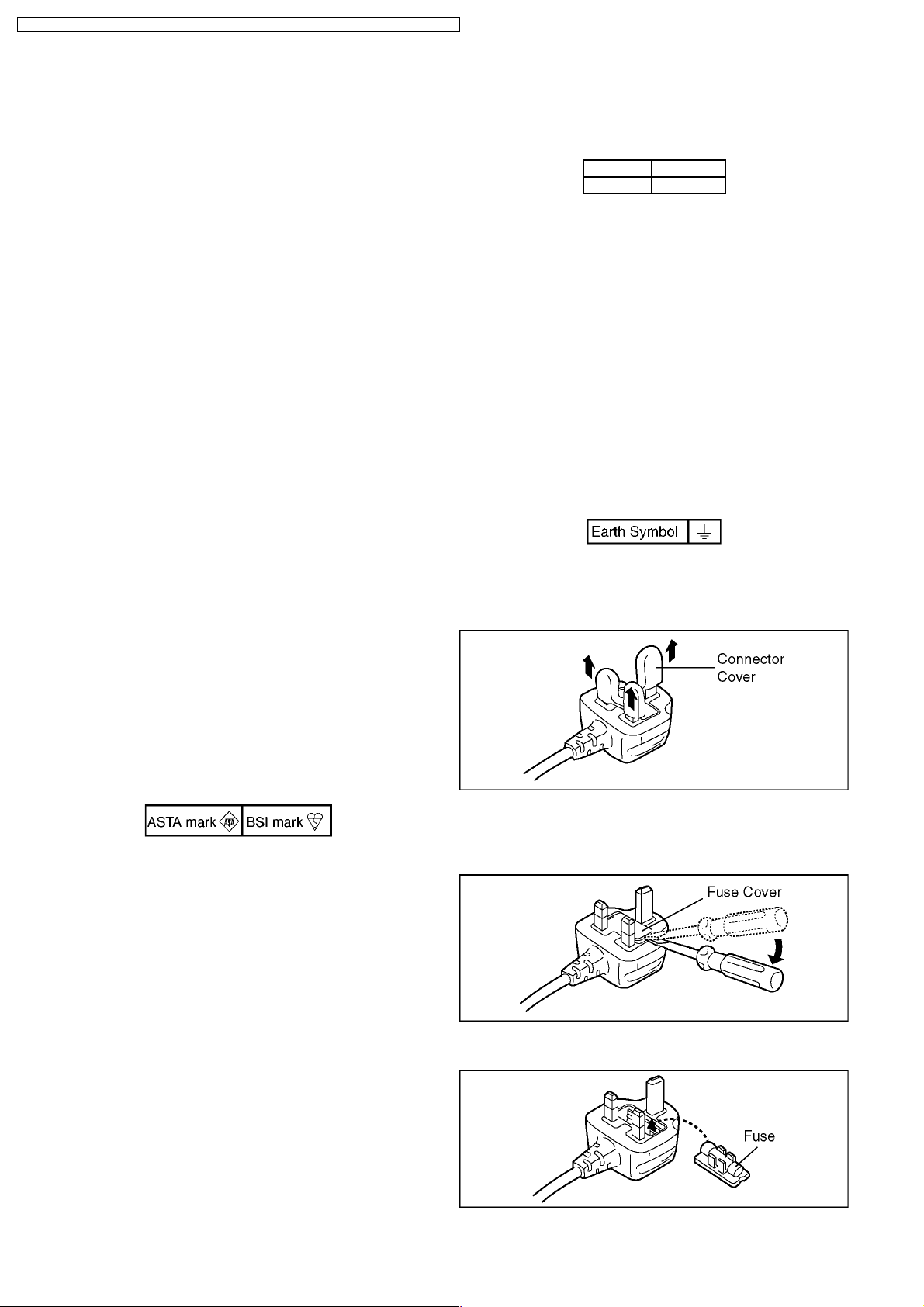
5.2.2. Before use
Remove the Connector Cover as follows.
5.2.3. How to replace the Fuse
1. Remove the Fuse Cover with a screwdriver.
If the fitted moulded plug is unsuitable for the socket outlet in
your home then the fuse should be removed and the plug cut
off and disposed of safety.
There is a danger of severe electrical shock if the cut off plug
is inserted into any 13-ampere socket.
If a new plug is to be fitted please observe the wiring code as
shown below.
If in any doubt, please consult a qualified electrician.
2. Replace the fuse and attach the Fuse cover.
8
Page 9

6 OPERATING GUIDE
DMC-L1KPP / DMC- L1KEB / DMC- L1KEG / DMC-L1KGC / DMC-L1KGK / DMC-L1KG N / DMC-L1KGT
9
Page 10

DMC-L1KPP / DMC- L1KEB / DMC- L1KEG / DMC-L1KGC / DMC-L1KGK / DMC-L1KG N / DMC-L1KGT11DMC-L1KPP / DMC- L1KEB / DMC- L1KEG / DMC-L1KGC / DMC-L1KGK / DMC-L1KG N / DMC-L1KGT
7 OPERATING INFORMATION
10
Page 11

Page 12

DMC-L1KPP / DMC- L1KEB / DMC- L1KEG / DMC-L1KGC / DMC-L1KGK / DMC-L1KG N / DMC-L1KGT13DMC-L1KPP / DMC- L1KEB / DMC- L1KEG / DMC-L1KGC / DMC-L1KGK / DMC-L1KG N / DMC-L1KGT
12
Page 13

Page 14

DMC-L1KPP / DMC- L1KEB / DMC- L1KEG / DMC-L1KGC / DMC-L1KGK / DMC-L1KG N / DMC-L1KGT15DMC-L1KPP / DMC- L1KEB / DMC- L1KEG / DMC-L1KGC / DMC-L1KGK / DMC-L1KG N / DMC-L1KGT
8 TROUBLESHOOTING
14
Page 15

Page 16

DMC-L1KPP / DMC- L1KEB / DMC- L1KEG / DMC-L1KGC / DMC-L1KGK / DMC-L1KG N / DMC-L1KGT17DMC-L1KPP / DMC- L1KEB / DMC- L1KEG / DMC-L1KGC / DMC-L1KGK / DMC-L1KG N / DMC-L1KGT
16
Page 17

Page 18

DMC-L1KPP / DMC- L1KEB / DMC- L1KEG / DMC-L1KGC / DMC-L1KGK / DMC-L1KG N / DMC-L1KGT
9 ERROR CODE MEMORY FUNCTION
1. General description
This unit is equipped with history of error code memory function, and can be memorized 32 error codes in sequence from the
latest. When the error is occurred more than 32, oldest error is overwritten in sequence.
The error code is not memorized when the power supply is shut down forcibly (when the unit is powered on by the battery, the
battery is pulled out) because the error code is memorized to FLASH ROM when the unit is powered off.
2. How to display
The error code can be displayed by the following procedure:
Before perform the error code memory function , connect the AC adaptor or insert the battery, and insert the SD card.
·1. The temporary cancellation of factory setting:
Set the shutter speed dial to “ 8
While pressing AFL/AEL
·2. The display of error code:
Press FUNC.2
The display is changed as shown below when the above buttons is pressed simultaneously.
Normal display o Error code display o Operation history display o Normal display o .....
, MENU/SET and “ LEFT of Cursor key” simultaneously with the step 1 condition.
”.
, then turn the Power on.
Example of Error Code Display
·3. The change of display:
The error code can be memorized 32 error codes in sequence, however it is displayed 5 errors on the LCD.
Display can be changed by the following procedure:
"UP
or DOWN of Cursor key": It can be scroll up or down one.
" LEFT
·4. How to read the error code:
One error code is displayed for 8 bit, the contents of error codes is indicated the table as shown below.
or RIGHT of Cursor key": It can be display last 5 error or another 5 error.
18
Page 19

DMC-L1KPP / DMC- L1KEB / DMC- L1KEG / DMC-L1KGC / DMC-L1KGK / DMC-L1KG N / DMC-L1KGT
Attribute Main item Sub item Error code Contents
High 4 bits Low 4 bits
LENS Lens
communication
HARD VENUS A/D Flash 2800 0000 Flash capacitor charge is not completed in time (20 seconds)
FLASH ROM
(EEPROM
Area)
SYSTEM RTC 2C00 0001 Clock IC initialize failure error
SOFT CPU Reset 3000 0001
Card Card 3100 0001 Card logic error
CPU,
ASIC hard
Operation Power on 3B00 0000 FLASH ROM processing camera initialization’s operating
Zoom Zoom 3C00 0000 The camera side doesn´t do completion of processing after the fixed
Communication 1800 0x01 Serial transmission error
0x02 Serial receive error
0x03 Before transmits L2B is not LoH error
0x04 After transmits L2B is not Ho L error
0x05 Before recieves L2B is not Lo H error
0x06 After recieves L2B is not HoL error
0x07 D data before recieves L2B is not LoH error
0x08 B command before execute L2B is not LoH error
0x09 B command while executing L2B is not HoL error
0x0A A command check sum error
0x0B B command check sum error
0x0C C command check sum error
0x0D D command check sum error
0x0E C command data check sum error
0x0F Reply data number error (except type C)
0x10 Reply data number error (type C)
FLASH ROM
(EEPROM
Area)
Stop 3800 0001 Camera task finish process time out
2B00 0001 EEPROM breakdown (reading : power ON)
0002 EEPROM (writing : power OFF and adjustment)
0007
0002 Card physical error
0004 Write error
3900 0005 Internal format error
0002 Camera task invalid code error
0003 AF time out error
3500 0000 The dummy processing is executed by the command from the sequence
3501 0000 The sequence side doesn´t respond though the record preprocessing is
3502 0000 The sequence shifted to the record without completing the record
User setting and storage area of menu information are cannot be
normally read
NMI reset (30000001-30000007 are caused by factors)
|
EEP superscription error factor address is stored in 108-109
time though the zoom stop is done from the sequence
to the camera processing (Illegal command issue)
necessary on the camera side
preprocessing on the camera side
·5. How to returned to Normal Display:
Turn the power off and on, to exit from Error code display mode.
NOTE:
The error code can not be initialized by the unit only.
19
Page 20

DMC-L1KPP / DMC- L1KEB / DMC- L1KEG / DMC-L1KGC / DMC-L1KGK / DMC-L1KG N / DMC-L1KGT
10 CONFIRMATION OF FIRMWARE VERSION
The Firmware version can be confirmed by ordering the following steps:.
·Step 1. The temporary cancellation of factory setting:
Insert the SD memory card which has a few photo data.
Set the shutter speed dial to “ 8
While keep pressing AFL/AEL
·Step 2. Confirm the version:
Press the “ Playback
Press FUNC.2
(The version information is displayed on the LCD with light blue colour letters.) (Fig. B)
CAUTION:
The version information does not display if the LCD has switched to LCD with indication already.
In this case, press DISPLAY
” button to playback mode, and then press [DISPLAY] to switch to LCD with indication. (Fig. A)
and “ DOWN of Cursor key” simultaneously. (No need to keep pressing.)
”.
, then turn the power on.
to switch to LCD with indication.
<Point>
·The firmware version and EEPROM version can be confirmed with the information (1).
·The information (2), (3) and (4) are just reference.
20
Page 21

11 MAINTENANCE
DMC-L1KPP / DMC- L1KEB / DMC- L1KEG / DMC-L1KGC / DMC-L1KGK / DMC-L1KG N / DMC-L1KGT
21
Page 22

DMC-L1KPP / DMC- L1KEB / DMC- L1KEG / DMC-L1KGC / DMC-L1KGK / DMC-L1KG N / DMC-L1KGT
22
Page 23

DMC-L1KPP / DMC- L1KEB / DMC- L1KEG / DMC-L1KGC / DMC-L1KGK / DMC-L1KG N / DMC-L1KGT
12 SERVICE NOTES
12.1. ABOUT THE LENS (Being Supplied as a KIT)
To minimize the possibilities of getting the dust/dirt on the lens surface, keep putting the lens cap other than necessary case.
The parts other than listed in replacement parts list are not allowed to disassemble/assemble.
It is not allowed to disassemble the Lens outside of the proper Clean facilities.
Once it is disassembled, proper adjustment/inspection facilities are required which are rather expensive.
12.2. ABOUT THE BODY
To squeeze the possibilities of getting the dust/dirt inside of the Mount space, keep putting the lens cap other than necessary case.
The parts other than listed in replacement parts list are not allowed to disassemble/assemble.
Since there is a open space especially in Finder unit, it gets dust/dirt easily.
Therefore, it is not allowed to replace the outer casing parts (such as Front, Rear, Top case and so on ) which are not listed in the
Replacement Parts list at the outside of the proper Clean facilities.
Besides, once it is disassembled, proper adjustment/inspection facilities are required which are rather expensive.
23
Page 24

DMC-L1KPP / DMC- L1KEB / DMC- L1KEG / DMC-L1KGC / DMC-L1KGK / DMC-L1KG N / DMC-L1KGT
13 DISASSEMBLY/ASSEMBLY
Refer to the following table and the illustration for disassembly
and assembly.
Part name Ref. No. Unscrew
Grip piece front (L) 14 B3, B15
Grip piece front (R) unit 40 B12, B13, B14
SD door unit 101 B22, B23
Shading frame 403 B401, B402, B403
24
Page 25

14 EXPLODED VIEWS
14.1. FRAME & CASING SECTION
DMC-L1KPP / DMC- L1KEB / DMC- L1KEG / DMC-L1KGC / DMC-L1KGK / DMC-L1KG N / DMC-L1KGT
25
Page 26

DMC-L1KPP / DMC- L1KEB / DMC- L1KEG / DMC-L1KGC / DMC-L1KGK / DMC-L1KG N / DMC-L1KGT
14.2. LENS SECTION
26
Page 27

DMC-L1KPP / DMC- L1KEB / DMC- L1KEG / DMC-L1KGC / DMC-L1KGK / DMC-L1KG N / DMC-L1KGT
14.3. PACKING PARTS & ACCESSORIES SECTION
27
Page 28

DMC-L1KPP / DMC- L1KEB / DMC- L1KEG / DMC-L1KGC / DMC-L1KGK / DMC-L1KG N / DMC-L1KGT
15 REPLACEMENT PARTS LIST
15.1. MECHANICAL REPLACEMENT
PARTS LIST
15.1.1. FRAME & CASING SECTION
PARTS LIST
Ref.
No.
14 VGQ8856 GRIP PIECE FRONT(L)
33 VMC2008 SHOE SPRING
40 VYF3095 GRIP PIECE FRONT (R) UNIT
101 VYF3093 SD DOOR UNIT
102-2 VYQ3887 EYE CUP
B1 VHD1680 SCREW
B2 VHD1680 SCREW
B3 VHD1684 SCREW
B4 VHD1684 SCREW
B5 VHD1892 SCREW
B6 VHD1892 SCREW
B7 VHD1892 SCREW
B8 VHD1892 SCREW
B9 VHD1892 SCREW
B10 VHD1892 SCREW
B11 VHD1892 SCREW
B12 VHD1892 SCREW
B13 VHD1892 SCREW
B14 VHD1892 SCREW
B15 XQN16+BJ5FJK SCREW
B16 XQN16+BJ5FJK SCREW
B17 XQN16+BJ5FJK SCREW
B18 VHD1689 SCREW
B19 VHD1690 SCREW
B20 VHD1690 SCREW
B21 VHD1690 SCREW
B22 XQN16+B2FN SCREW
B23 XQN16+B2FN SCREW
15.1.2. LENS SECTION PARTS LIST
Ref.
No.
403 VDW1327 SHADING FRAME
406 VMG1735 ZOOM RUBBER RING
B401 XQN14+B3FNK SCREW
B402 XQN14+B3FNK SCREW
B403 XQN14+B3FNK SCREW
Part No. Part Name & Description Remarks
Part No. Part Name & Description Remarks
15.1.3. PACKING PARTS & ACCESSORIES
SECTION PARTS LIST
Ref.
No.
500 VYC0949 HOOD UNIT
500-1 VPF1263 HOOD BAG
501 VFC4185 LENS REAR CAP
502 VPF1262 LENS BAG (POLYETHYLENE)
503 VYF3089 LENS FRONT CAP
505 VPF1166 CAMERA BAG
507 DE-972AF AC ADAPTOR PP
507 DE-972CE AC ADAPTOR GC,GK
507 DE-972BF AC ADAPTOR GN,EB,EG
507 DE-972FE AC ADAPTOR GT
509 K2GJ2DZ00028 DC CABLE
510 VFC4189 STRAP
510-1 VGQ8990 EYEPIECE CAP
511 VFC4206 LENS STORAGE BAG
512 VFF0330-S CD-ROM (BUNDLE SOFT) PP
512 VFF0331-S CD-ROM (BUNDLE SOFT) GC,GN,GK,GT,
513-1 VPF1100 BAG, POLYETHYLENE PP
513-1 VPF1166 BAG,POLYETHYLENE GC,GN,GK,GT,
513-2 VQT0W41 O/I PC CONN.
513-2 VQT0W47 O/I PC CONN.
513-2 VQT0Z48 O/I PC CONN.
513-2 VQT0W46 O/I PC CONN.
513-2 VQT0W49 O/I PC CONN.
513-2 VQT0W48 O/I PC CONN.
513-2 VQT0W43 O/I PC CONN.
513-2 VQT0W44 O/I PC CONN.
513-3 VQT0W82 INSTRUCTION BOOK
513-3 VQT0W83 INSTRUCTION BOOK
513-3 VQT0W89 INSTRUCTION BOOK
513-3 VQT0W90 INSTRUCTION BOOK
513-3 VQT0W95 INSTRUCTION BOOK
513-3 VQT0W94 INSTRUCTION BOOK
513-3 VQT0W93 INSTRUCTION BOOK
513-3 VQT0W88 INSTRUCTION BOOK
513-3 VQT0W84 INSTRUCTION BOOK (GERMAN) EG
513-3 VQT0W85 INSTRUCTION BOOK (FRENCH) EG
513-4 VQT0Z34 O/I SOFTWARE
513-4 VQT0Z37 O/I SOFTWARE
513-4 VQT0Z36 O/I SOFTWARE (ENGLISH) GN,EB
513-4 VQT0Z39 O/I SOFTWARE
513-4 VQT0Z38 O/I SOFTWARE
513-4 VQT0Z35 O/I SOFTWARE
Part No. Part Name & Description Remarks
EB,EG
EB
(ENGLISH(SPANISH)/
CANADIAN FRENCH)
(ENGLISH/ARABIC/
CHINESE(TRADITIONAL))
(RUSSIAN)
(ENGLISH)
(CHINESE(SIMPLIFIED))
(CHINESE(TRADITIONAL))
(GERMAN/FRENCH/
ITALIAN/DUTCH)
(SPANISH/SWEDISH/DANISH/
PORTUGUESE)
(ENGLISH(SPANISH))
(CANADIAN FRENCH)
(ENGLISH)
(CHINESE(TRADITIONAL))
(ENGLISH)
(CHINESE(SIMPLIFIED))
(CHINESE(TRADITIONAL))
(ENGLISH)
(ENGLISH/CANADIAN FRENCH)
(ENGLISH/RUSSIAN/ARABIC/
CHINESE(TRADITIONAL))
(CHINESE(SIMPLIFIED))
(CHINESE(TRADITIONAL))
(GERMAN/FRENCH/ITALIAN/
DUTCH/PORTUGUESE/SPANISH/
SWEDISH/DANISH)
PP
GC
GC
GN,EB
GK
GT
EG
EG
PP
PP
GC
GC
GN
GK
GT
EB
PP
GC
GK
GT
EG
28
Page 29

DMC-L1KPP / DMC- L1KEB / DMC- L1KEG / DMC-L1KGC / DMC-L1KGK / DMC-L1KG N / DMC-L1KGT
Ref.
No.
514 K1HA05CD0004 USB CABLE
515 K2KJ2CB00001 AV CABLE
520 VPK3145 PACKING CASE PP
520 VPK3146 PACKING CASE GC,GN,GK,GT,
521 VPN6424 CUSHON A
522 VPN6425 CUSHON B
523 VPN6447 PAD
526 VKF4091 BODY CAP
530 K2CA2CA00019 AC CABLE PP
531 K2CQ2CA00006 AC CORD W/PLUG GC,EG
532 K2CT3CA00004 AC CORD W/PLUG GC,EB
533 K2CJ2DA00008 AC CORD W/PLUG GN
534 K2CA2CA00020 AC CORD W/PLUG GK
534 K2CA2CA00027 AC CORD W/PLUG GT
Part No. Part Name & Description Remarks
EB,EG
29
 Loading...