

USER’S MANUAL
WLAN Adaptor
POWER
LINK
RESET
SETUP
Model No. CZ-CAPWFC1
Contents
Safety Precautions ...................................... 2
System Overview ......................................... 5
Parts Identication ...................................... 6
Parts.............................................................. 7
Dimensions .................................................. 7
WLAN Adaptor Installation ......................... 8
Connecting Network .................................. 11
Use the “Panasonic Comfort Cloud” ....... 18
WLAN Adaptor Q & A ................................ 27
Firmware Update Function ....................... 29
Software License Information .................. 29
Specications ............................................ 36
Thank you for purchasing this Panasonic product.
Please read these instructions carefully before using this product, and save this
manual for future use.
Panasonic Corporation
1006 Kadoma, Kadoma City, Osaka, Japan
Panasonic Corporation
http://www.panasonic.com
F1218-20119
ACXF60-34442
Please Read Before Starting
These instructions are all you need for most installation sites and maintenance
conditions. If you require help for a special problem, contact our sales/service outlet or
your certied dealer for additional instructions.
The English text are the original instructions. Other languages are translations
of the original instructions.
Safety Precautions
We assume no responsibility for accidents or damages resulting from methods other
than those described in the USER’S MANUAL or methods without using specied parts.
Malfunctions that occur due to the unauthorised installation methods are not covered
by the product warranty.
●
This WLAN Adaptor shall be installed in accordance with National Wiring Regulations.
● Read the installation instructions of devices to be connected as well.
● When relocating or repairing this WLAN Adaptor, provide the USER’S MANUAL to
the servicing personnel.
● Please provide this USER’S MANUAL to the user after installation.
Instruct user to keep it in a safe place along with the air conditioner instruction
manuals.
WARNING
CAUTION
This symbol refers to a hazard or unsafe practice which can result in
severe personal injury or death.
This symbol refers to a hazard or unsafe practice which can result in
personal injury or product or property damage.
Precautions for Installation setup and WLAN Adaptor
WARNING
z Turn off the circuit breaker of the units before installation.
z Select an installation location which is rigid and strong enough to
support or hold the WLAN Adaptor, and select a location for easy
maintenance.
z Use only the parts specied by Panasonic as supplied
accessories.
z Ensure cables are installed properly so that external forces cannot
affect them.
z Disassembly and modication of the WLAN Adaptor is not
permitted under any circumstances.
2
WARNING
z The WLAN Adaptor must be installed by the sales dealer or
installer.
z When installing the WLAN Adaptor, use appropriate protective
equipment and tools for safety.
z The WLAN Adaptor should be securely installed in accordance
with the USER’S MANUAL.
z Electric work must be performed by authorised personnel in
accordance with the local regulations and the instructions detailed
in the USER’S MANUAL.
z To avoid malfunctions caused by radio wave interference, keep the
WLAN Adaptor away from devices such as other wireless device,
microwaves and the device that use 2.4 GHz signal. Depending on
the area, the module may not be available.
z Attach the electrical cover to the indoor unit securely.
z Make sure to connect the WLAN Adaptor to the P.C. board and
terminal board of the indoor unit properly.
z Do not set up in hospitals or places where electronic medical
devices are located.
z If you have a cardiac pacemaker or implantable cardioverter
debrillator, please keep at least 15 cm away from the WLAN
Adaptor.
z Do not use the WLAN Adaptor near to automatic control
equipment (automatic door, re alarms, etc.).
z In case of an abnormal condition (such as a burning smell), stop
the indoor unit and turn the breaker OFF.
z Do not operate with wet hands.
z Do not splash water on the WLAN Adaptor or use it in the
bathroom.
3
CAUTION
z Ground yourself to discharge static electricity before performing
any wiring.
z Do not install the WLAN Adaptor in places with direct sunlight or
where the ambient temperature is 55 ˚C or more or is 0 ˚C or less.
z The connecting cable must not touch piping directly.
z Do not set up where children can reach the WLAN Adaptor.
z Do not stand on an unstable surface when operating or checking
the WLAN Adaptor.
z Do not use in special environments.
Use in places with much oil (including machine oil), steam,
ammable or corrosive gas, voltage uctuation, surrounding the
metal body, may lead to severe decrease in functionality and
damage to parts.
z Do not use the WLAN Adaptor nearby other wireless devices,
microwaves, cordless phones, or facsimiles.
z This equipment is not suitable for use in locations where children
are likely to be present.
z This appliance is not intended for use by persons (including
children) with reduced physical, sensory or mental capabilities, or
lack of experience and knowledge, unless they have been given
supervision or instruction concerning use of the appliance by a
person responsible for their safety. Children should be supervised
to ensure that they do not play with the appliance.
<for European market only>
This appliance can be used by children aged from 8 years and
above and persons with reduced physical, sensory or mental
capabilities or lack of experience and knowledge if they have
been given supervision or instruction concerning use of the
appliance in a safe way and understand the hazards involved.
Children shall not play with the appliance. Cleaning and user
maintenance shall not be made by children without supervision.
4
NOTE
● Install the WLAN Adaptor vertically or horizontally.
● When attaching the WLAN Adaptor, be sure to use the supplied screws and
conrm that the WLAN Adaptor is xed to the surface so that there are no gaps.
● The warranty does not cover the product if it falls from an elevated location.
● The WLAN coverage must include the air conditioner installation location.
● Please write down the model information and more on the last page “Setting
Information”, when you install the WLAN Adaptor.
● Requires a smartphone or tablet that is iOS/Android compatible.
● Please ensure that the Router supports the WPA2-PSK (TKIP/AES) encryption
setting before commencement of the installation of this WLAN Adaptor.
● To complete connection of this WLAN Adaptor to the wireless network service the
Router may be required.
● The End user should read and accept the Terms of use and Privacy Notice in the
contents of “Panasonic Comfort Cloud” app.
● Please avoid to set up multiple WLAN Adaptor registrations at the same time.
● There is a risk of unauthorised operation if a vulnerable password is set for the
wireless router.
● Users are responsible for all costs associated with downloading and using the
Comfort Cloud App and WLAN Adaptor, including without limitation all fees
charged by your Device carrier and internet service provider and any other WLAN
or data access charges.
● Panasonic WLAN Adaptor is designed for communication to the “Panasonic
Comfort Cloud”.
● Third party WLAN interfaces cannot be connected to the “Panasonic Comfort
Cloud”.
● Updates to the service may mean there are changes to the design of the
“Panasonic Comfort Cloud” app screen and display.
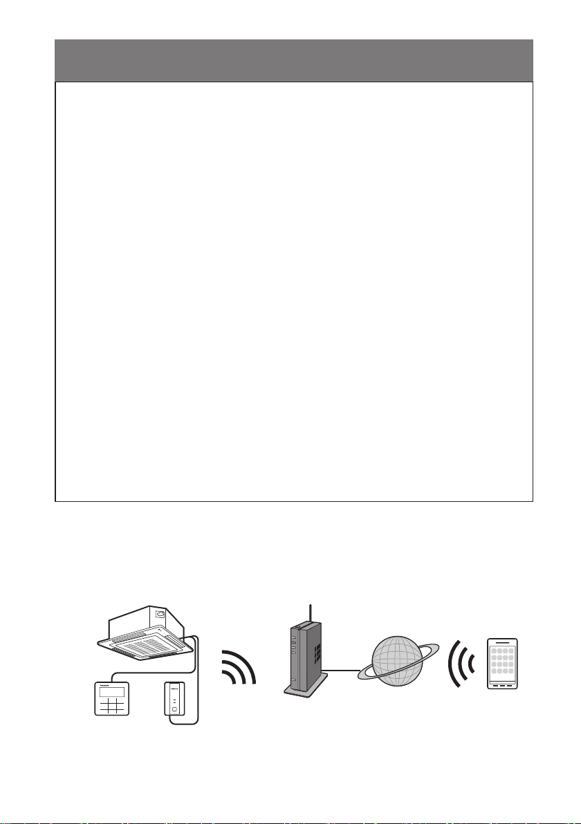
System Overview
Indoor unit (example: 4-way cassette)
Wired remote
controller
POWER
LINK
RESET
SETUP
WLAN Adaptor
CZ-CAPWFC1
Wireless
LAN
Router
Internet
Smartphone
5
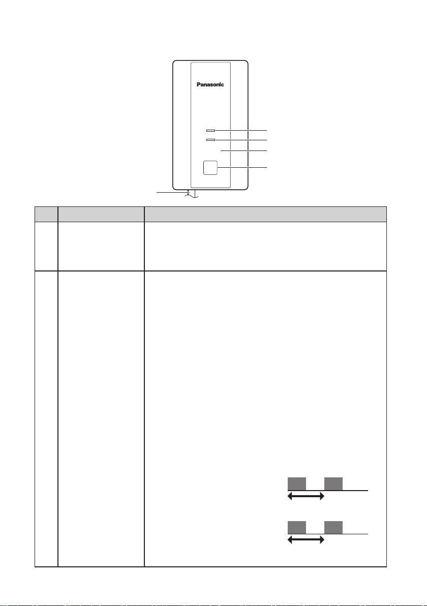
Parts Identication
POWER
LINK
RESET
SETUP
1
2
3
4
5
No Item Description
Indicates that the WLAN Adaptor is being supplied with
POWER LED
1
(green)
2 LINK LED (green)
power.
On : Power being supplied
Off : No power being supplied
Indicates the communication status of the WLAN Adaptor
to the router.
Off : Not connected to router
Blinks : In the process of connecting with router
On : Connected to router
The LINK LED does not light if the WLAN Adaptor cannot
connect with a router.
The following are cases with special LED indications.
● When SETUP button is pressed and held
The LED blinks to indicate how much time has elapsed.
Blinks once after 5 seconds have elapsed
Blinks twice after 10 seconds have elapsed
Blinks three times after 15 seconds have elapsed
Blinks four times after 20 seconds have elapsed
Blinks ve times after 25 seconds have elapsed
Blinks six times after 30 seconds have elapsed
Lights constantly after 35 seconds have elapsed
● When operating in WPS mode
Blinks at 1.0-second intervals
1.0-second interval
● When operating in AP mode
Blinks at 0.5-second intervals
0.5-second interval
6
No Item Description
3 RESET button*
4 SETUP button*
Resetting the hardware
Use to restart the WLAN Adaptor.
Used when making network settings.
Refer to “Connecting Network” (Page 11) for details.
These are the communication lines connecting the indoor
Communication
5
lines (L=1.9 m)
units and the WLAN Adaptor.
Refer to “WLAN Adaptor Installation” (Pages 8, 9)
for details.
* Initialising the WLAN Adaptor
Press and hold the SETUP button (30 to 35 seconds). After this, press the RESET
button within 5 seconds to initialise.
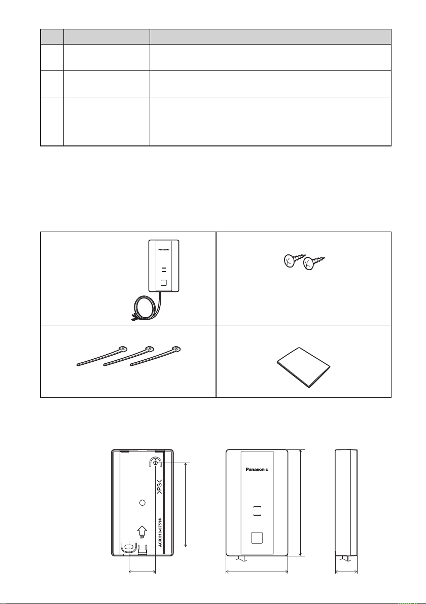
Parts
Adaptor Unit (1)
(CZ-CAPWFC1)
Clamper (3)
Dimensions
Screw (2)
POWER
LINK
RESET
SETUP
M3.8 x 16
USER’S MANUAL (1)
95
POWER
LINK
RESET
SETUP
120
30
70 24.8
(mm)
7
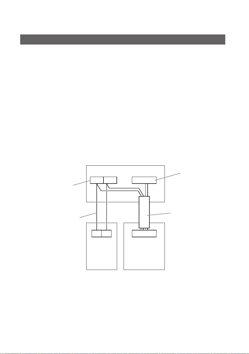
WLAN Adaptor Installation
Basic Wiring Diagram
Irrespective of the number of indoor units, the WLAN Adaptor must be used together
with a remote controller.
A remote controller must be connected and it should be set as the “main unit” in the
main-sub remote controller settings.
● Refer to the remote controller installation instructions for details on how to make the
main-sub settings for the remote controller.
● Total length of remote controller wiring: Within 500 m
(Remote controller wiring between indoor units is within 200 m)
● Number of units that can be connected for group control
• Indoor units : Up to 8 units
• WLAN Adaptor : 1 unit
• Wired remote controller : 1 unit
● The system operates irrespective of the indoor unit you choose to connect the
WLAN Adaptor and remote controller to.
When there is 1 indoor unit
Example
Terminals for remote
controller wiring
Indoor unit
R1 R2
T10
T10 connector
Remote controller wiring
(eld supply)
● No polarity
8
1 2
Wired
remote
controller
(main unit)
Communication lines
(1.9 m total length)
CN03
WLAN Adaptor
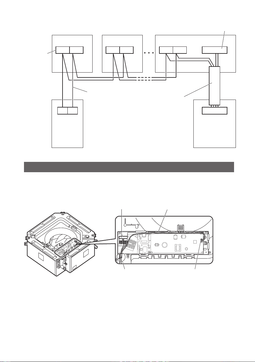
When there are multiple indoor units
Example
Indoor unit
Indoor unit Indoor unit
T10 connector
Terminals
for remote
controller
wiring
R1 R2 R1 R2
Remote controller
wiring
1 2
Wired
remote
controller
(main unit)
(eld supply)
● No polarity
Communication lines
(1.9 m total length)
Example of standard installation
Connect the communication lines to the indoor unit.
1
Example: With a 4-way cassette indoor unit
Remote controller terminal board
Thread the leads through the
catches in the electrical box.
T10R1 R2
CN03
WLAN Adaptor
Fix in place with the included
clampers
● Fix the communication lines in place with the included clampers*.
* Make sure the clampers hold the parts coated in white.
● Lead wires* with crimper terminals should be connected to the remote
controller terminal board. Lead wires* with connectors should be connected to
the T10 connector.
* There may be left over lead wires depending on the type of indoor unit. Tie
back left over lead wires with the included clampers.
* The lead wires with crimper terminals have no polarity.
T10 connector
9
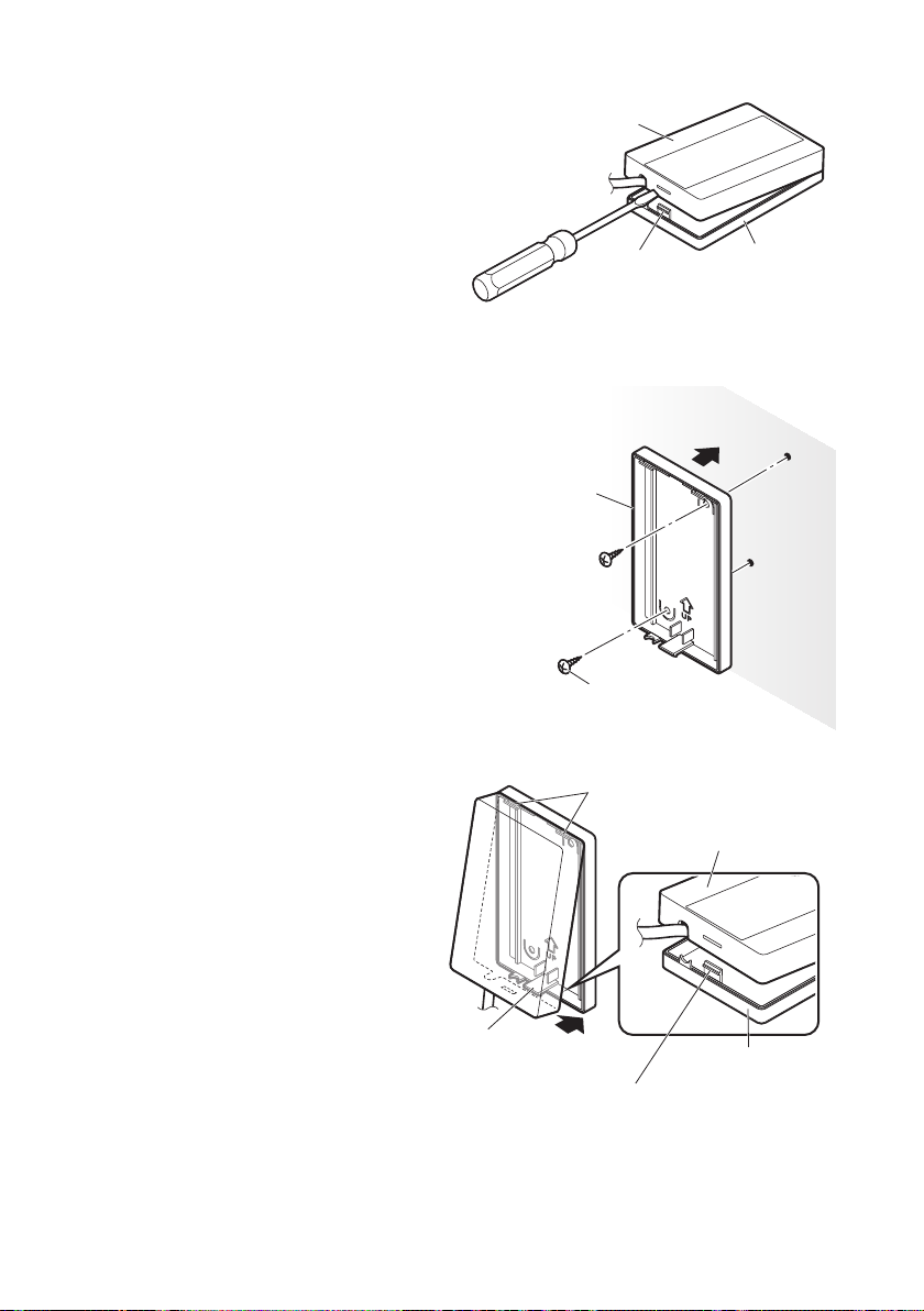
Remove the top case.
2
Use a at head screwdriver or similar
tool to push in the catch on the bottom
case and remove the top case.
Take care not to break the catch when
pushing with the screwdriver.
Top case
When attaching the bottom
3
case to the wall
Screws (supplied): 2
Attach the WLAN Adaptor to the wall
with the UP mark facing upwards.
Please ensure screws are tightened
rmly. Do not overtighten screws as
this may damage the casing.
Ensure that the screws do not contact
metallic parts within the wall.
Attach the top case.
4
Fit the upper catches before
tting the lower catch.
Take care not to pinch the
communication lines in the
case.
Bottom case
Catch
Wall to which the
WLAN Adaptor is xed
Screw (supplied)
Upper catches (2 places)
Bottom case
Top case
10
Lower catch
Bottom case
When tting the lower catch, press down on it with a at head
screwdriver or similar tool and then t the top case onto it.
* Note that applying too much pressure to the at head screwdriver
may result in damage to the catch.
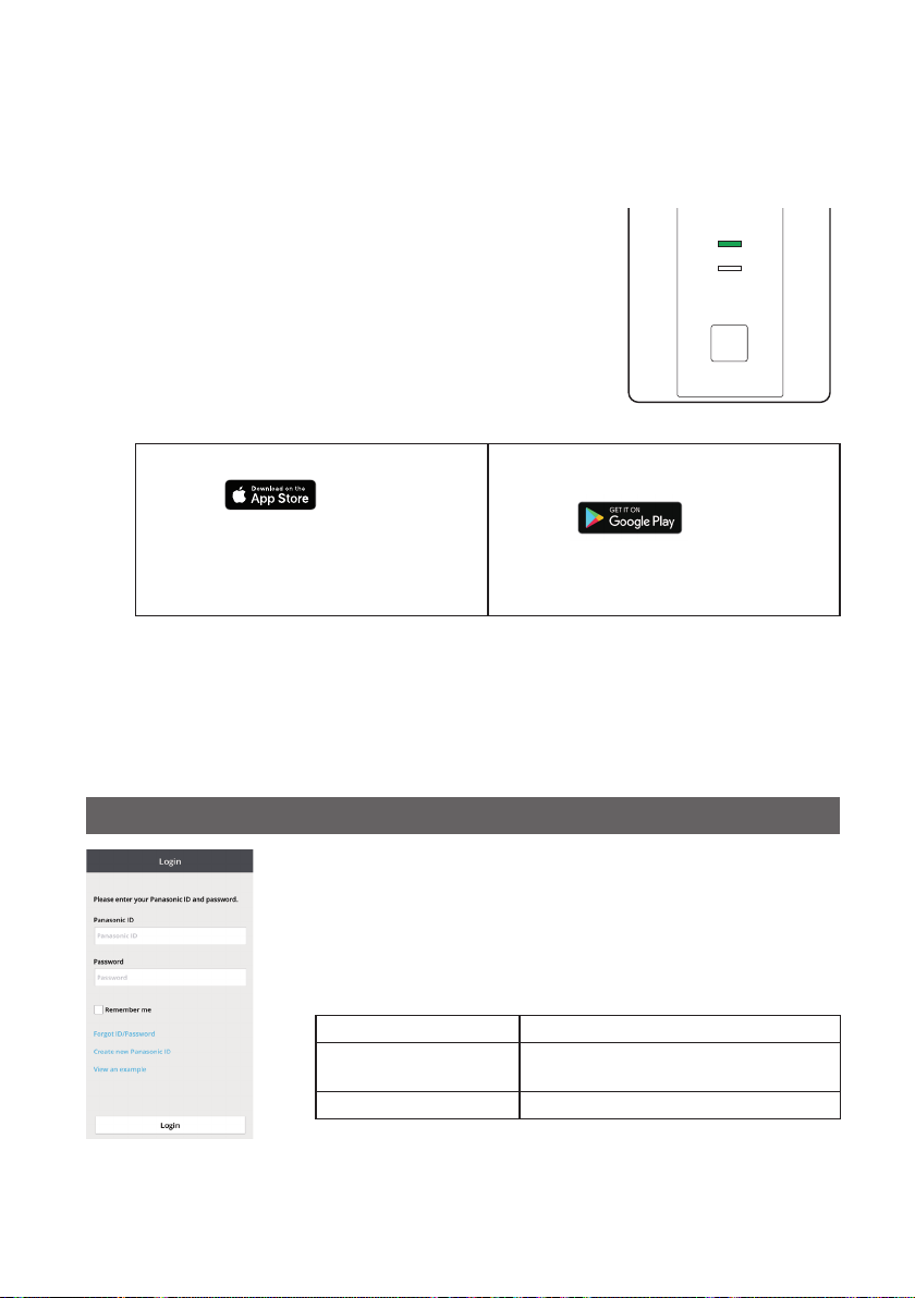
Connecting Network
Establish network connection to the internet via Wireless mode.
Turn on the power supply to the indoor unit.
1
– The POWER LED will be lit (green).
– The LINK LED will not be lit.
<Note>
● It will not be possible to make network settings for
approximately 3 minutes after turning on the power of the
WLAN Adaptor due to initial settings being performed.
App Installation
2
For iOS user (iOS 9 and above)
● Open
● Search for “Panasonic Comfort
Cloud” app.
● Download and install.
<Note>
● The app user interface image may change for version upgrade without noti cation.
● There is no charge for using this application. However, other charges may be incurred
for connection and operation.
.
For Android user (Android 4.4 and
above)
● Open
● Search for “Panasonic Comfort
Cloud” app.
● Download and install.
POWER
LINK
RESET
SETUP
.
Starting “Panasonic Comfort Cloud”
3
3.1 Create New Panasonic ID
Use “Panasonic Comfort Cloud” app as an option to control
the air conditioner.
● For new user, select Create new Panasonic ID to register.
Password must be 8-16 characters with letters and
numbers.
You can input the following characters. (As of January 2019)
Numeric characters 0123456789
Alphabetical characters
(upper and lower cases)
Symbols ~`!@#$%^&*()-_+={}[]
● For registered user, login using your Panasonic ID and
password.
<Note>
● It is recommended that the password is changed periodically.
ABCDEFGHIJKLMNOPQRSTUVWXYZ
abcdefghijklmnopqrstuvwxyz
11
 Loading...