

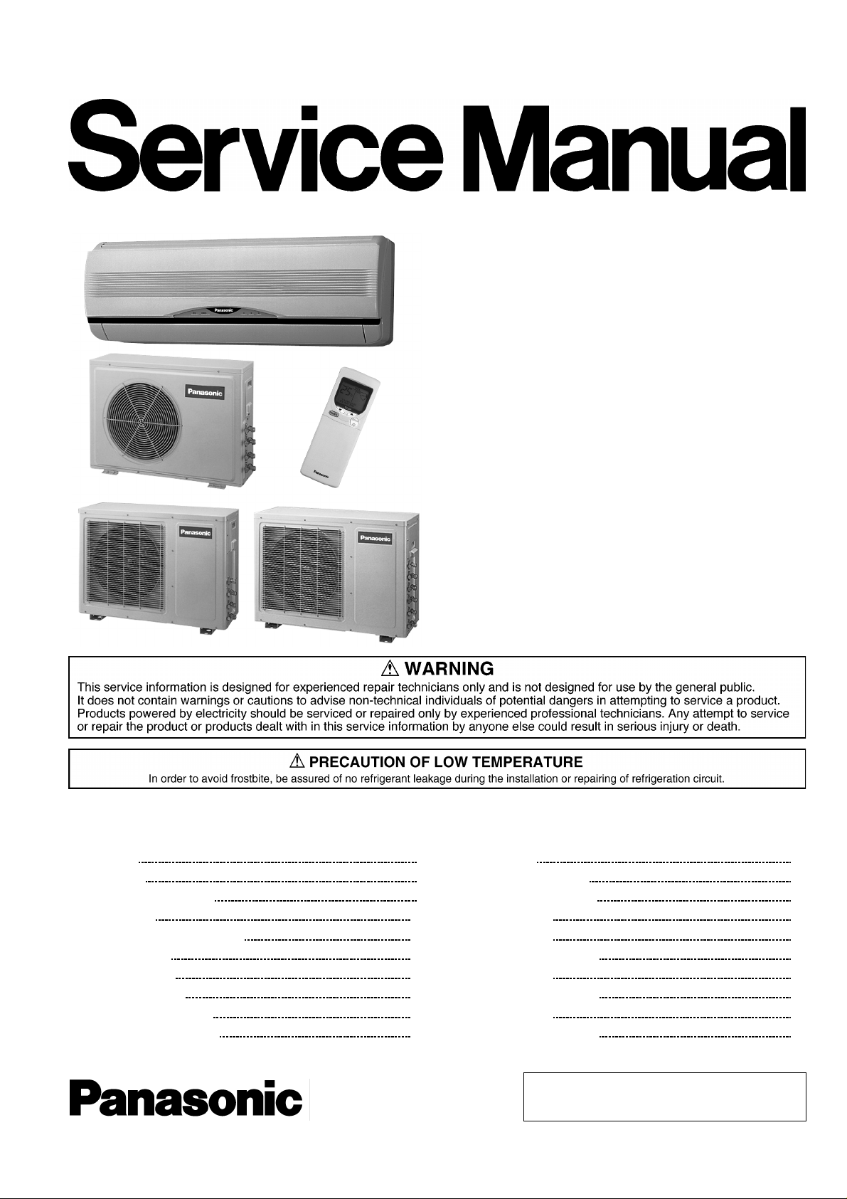
Panasonic CS-C7BKPG, CU-C9BKPG, CU-2C14BKP5G, CU-3C20BKP5G Service Manual
Order No. MAC0201004C8
Multi-Split Air Conditioner
CS-C9BKPG CU-2C14BKP5G
CS-C9BKPG CU-2C18BKP5G
CS-C9BKPG CU-3C20BKP5G
CS-C7BKPG CU-2C19BKP5G
CS-C12BKPG
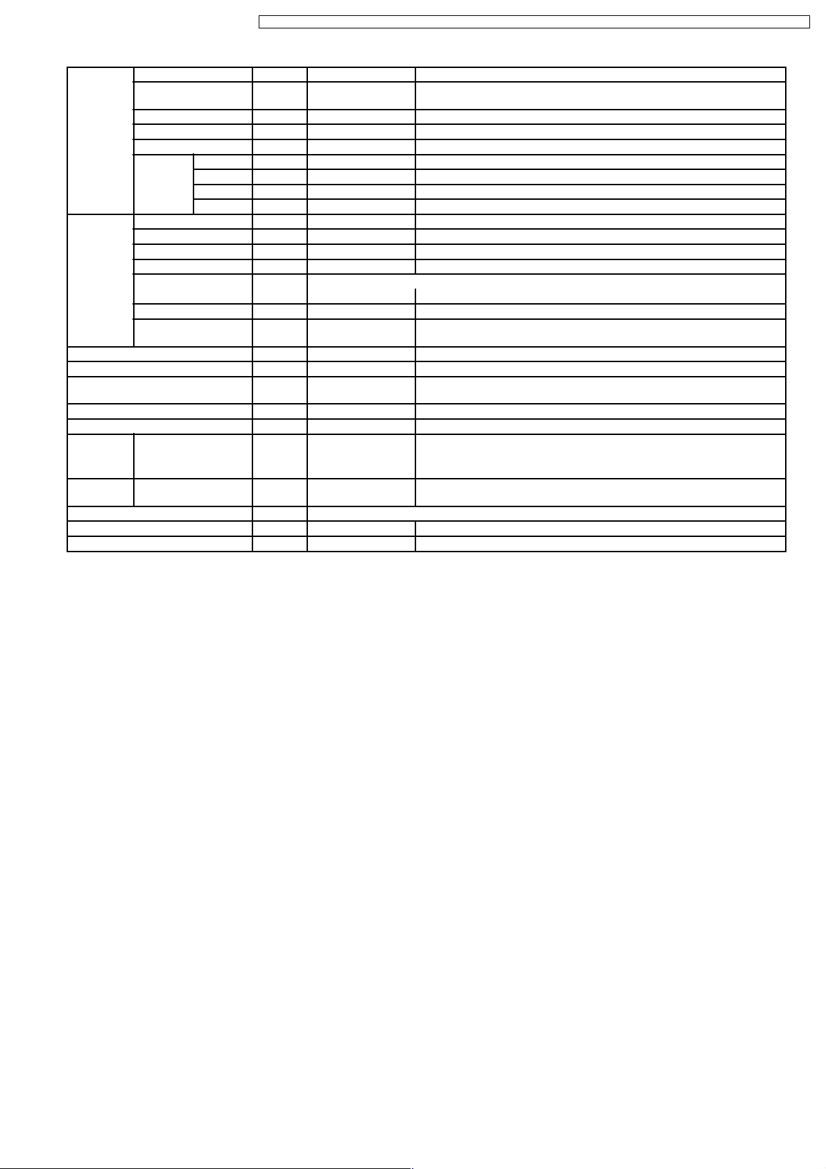
CONTENTS
Page Page
1 Features 2
2 Functions
3 Product Specifications
4 Dimensions
5 Refrigeration Cycle Diagram
6 Block Diagram
7 Wiring Diagram
8 Operation Details
9 Operating Instructions
10 Installation Instructions
11 3-way Valve 49
12 Servicing Information
3
6
13 Troubleshooting Guide
14 Technical Data
14
16
15 Exploded View
18
16 Replacemen t Parts List
17 Exploded View
22
26
18 Replacemen t Parts List
19 Exploded View
34
39
20 Replacemen t Parts List
© 2002 Matsushita Air-Conditioning Corp. Sdn. Bhd.
(183914D). All rights reserved. Unauthorized copying
and distribution is a violation of law.
56
60
62
69
70
71
72
73
74

CS-C9BKPG CU-2C14BKP5G / CS-C9BKPG CU-2C18BKP5G / CS-C9BKPG CU-3C20BKP5G / CS-C7BKPG CU-2C19BKP5G / CS-C12BKPG
21 Exploded View 75
22 Replacemen t Parts List
23 Exploded View
76
77
1 Features
High Efficiency
•
Compact Design
•
Comfort Environment
•
8 hours of sleep mode operation
−
Air filter with function to reduce dust and smoke
−
Wider range of horizontal discharge air
−
Auto Restart
•
Random auto restart after power failure for safety restart
−
operation
Removable and Washable Front Panel
•
24 Replacemen t Parts List 78
25 Electronic Parts List
26 Electronic Circuit Diagram
Quality Improvement
•
Gas leakage protection
−
Prevent compressor reverse cycle
−
2-stage OLP to protect compressor
−
Noise prevention during soft dry operation.
−
Anti-dew Formation Control (Cooling & Soft Dry)
−
Operation Improvement
•
Economy mode to reduce electrical power consumption
−
Powerful mode to reach the desired room temperature
−
79
80
quickly
Long Installation Piping
•
Long piping up to 15 meter
−
Remote Control Self-illuminating Button
•
Catechin Air Purifying Filter
•
Trap dust, tobacco smoke and tiny particles
−
Prevent the growth of bacteria and viruses trapped
−
Solar Refreshing Deodorizing Filter
•
Remove unpleasant odour from the air
−
24-hour Timer Setting
•
2
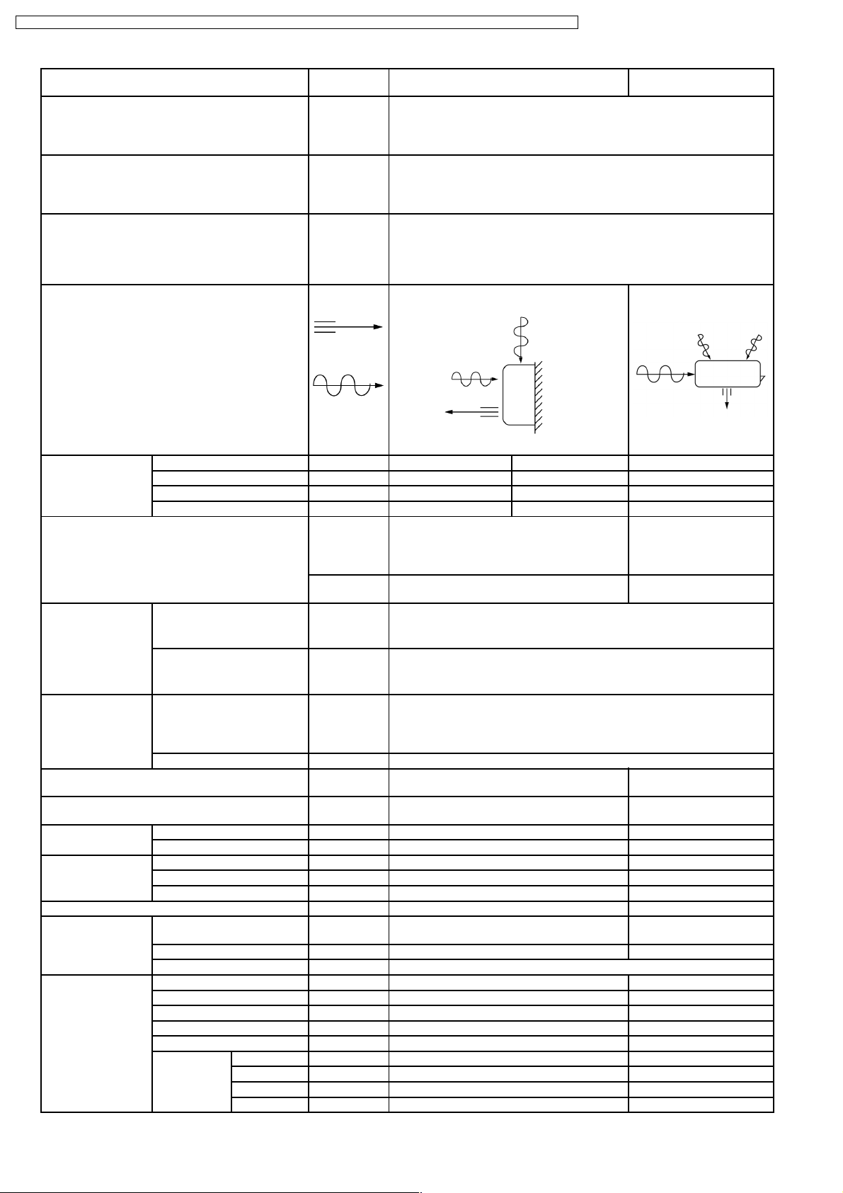
2 Functions
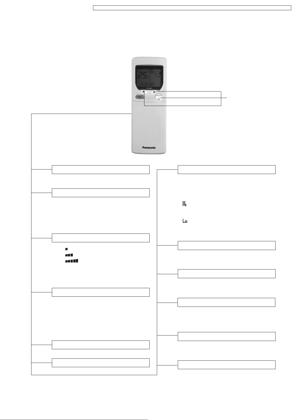
Remote Control
CS-C9BKPG CU-2C14BKP5G / CS-C9BKPG CU-2C18BKP5G / CS-C9BKPG CU-3C20BKP5G / CS-C7BKPG CU-2C19BKP5G / CS-C12BKPG
Self illuminating
button
OFF / ON I
MODE
FAN SPEED
AIR SWING
POWERFUL
Operation OFF / ON
Operation Mode Selection
•
•
•
•
AUTO
COOL
DRY
FAN
Automatic Operation Mode
Cooling Operation Mode
Soft Dry Operation Mode
Air Circulation Mode
Indoor Fan Speed Selection
•
FAN
Low Fan Speed
•
FAN
Medium Fan Speed
•
FAN
High Fan Speed
•
AUTO
FAN
Automatic Fan Speed
Vertical Airflow Direction Control
•
AUTO
Automatic Vertical Airflow
Direction Control
•
MANUAL
Vertical Airflow Direction
Manual Control (5 stages of
adjustment)
Powerful Mode Operation OFF/ON
TEMP.
ON-TIMER
OFF-TIMER
TIME
SET
CANCEL
CLOCK
Room Temperature Setting
Cooling, Soft Dry, Air Circulation Operation.
• Temperature Setting (16°C to 30°C)
Automatic Operation
•
Operation with 2°C higher than
standard temperature.
• Operation with standard temperature.
•
Operation with 2°C lower than
standard temperature.
Timer Operation Selection
• 24-hour, OFF / ON Real Timer Setting.
Time / Timer Setting
• Hours and minutes setting.
Timer Operation Set / Cancel
• ON Timer and OFF Timer setting and
cancellation.
Clock Setting
• Current time setting.
ECONOMY
Economy Mode Operation OFF/ON
3
SLEEP
Sleep Mode Operation OFF / ON
CS-C9BKPG CU-2C14BKP5G / CS-C9BKPG CU-2C18BKP5G / CS-C9BKPG CU-3C20BKP5G / CS-C7BKPG CU-2C19BKP5G / CS-C12BKPG
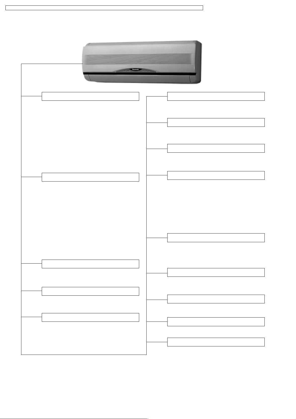
Indoor Unit
AUTO
OFF / ON
Automatic Operation Button
Random Auto Restart Control
• Press for < 5s to operate Automatic
operation mode.
(Used when the remote control cannot be used.)
• Press continuously for 5s or < 10s to
operate Test Run/Pump down. “Beep”
sound will be heard at the 5th second.
(Used when test running or servicing.)
• Press continuously for 10s and above to
omit or resume the remote control signal
receiving sound. “Beep, beep” sound will
be heard at the 10th second.
Operation Indication Lamps (LED)
•
POWER
(Green) ........Lights up in operation,
blinks in Automatic
Operation Mode
judging.
•
SLEEP
(Orange)........ Lights up in Sleep
Mode Operation.
•
TIMER
(Orange) .......Lights up in Timer
Setting.
•
POWERFUL
(Orange)..Lights up in Powerful
Mode Operation.
•
ECONOMY
(Green) ..... Lights up in Economy
Mode Operation.
Operation Mode
• Cooling, Soft Dry, Air Circulation and
Automatic Mode.
Powerful Operation
• Reaches the desired room temperature
quickly.
• Operation is restarted randomly after
power failure at previous setting mode.
Anti-Freezing Control
• Anti-Freezing control for indoor heat
exchanger. (Cooling and Soft Dry)
Sleep Mode Auto Control
• Indoor Fan operates at Low speed.
• Operation stops after 8 hours.
Indoor Fan Speed Control
• High, Medium and Low.
• Automatic Fan Speed Mode
– Cooling : Fan rotates at Hi, Me and
SLo speed. Deodorizing
control is available.
– Soft Dry: Fan rotates at SLo speed.
Deodorizing control
is available.
Airflow Direction Control
• Automatic air swing and manual adjusted
by remote control for vertical airflow.
•
Manually adjusted by hand for horizontal airflow.
Starting Current Control
• Fan motor is delayed for 1.6 seconds
when compressor starts simultaneously.
Time Delay Safety Control
•
Restarting is inhibited for appro. 3 minutes.
Economy Operation
• To reduce electrical power consumption.
7 Minutes Time Save Control
• Cooling Operation only.
Anti-Dew Formation Control
• Anti-Dew Formation Control for indoor
unit discharge area.
4
CS-C9BKPG CU-2C14BKP5G / CS-C9BKPG CU-2C18BKP5G / CS-C9BKPG CU-3C20BKP5G / CS-C7BKPG CU-2C19BKP5G / CS-C12BKPG
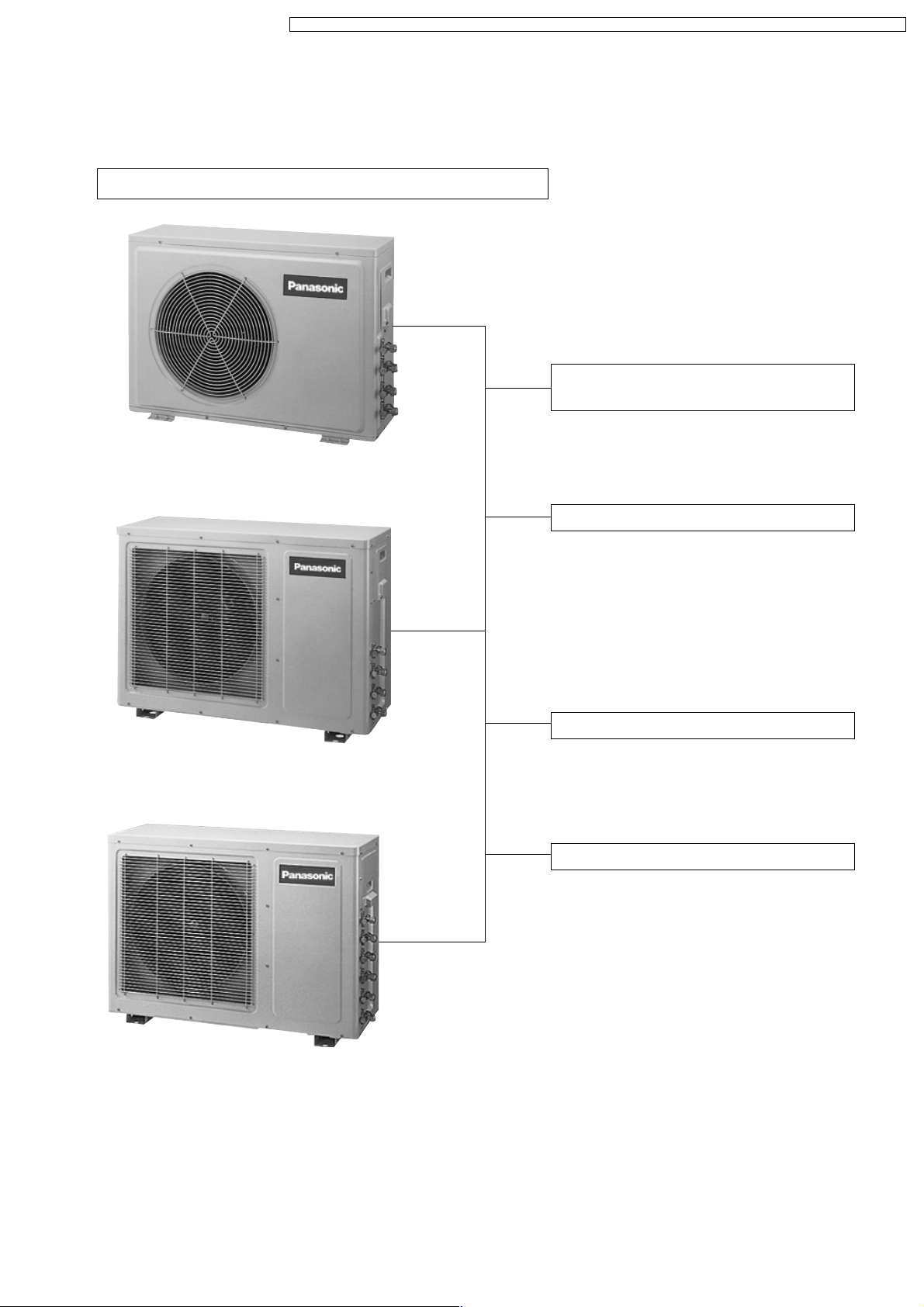
Outdoor Unit
CU-2C14BK, CU-2C18BK, CU-2C19BK & CU-3C20BK
Compressor Reverse Rotation
Protection Control
• To protect compressor from reverse
rotation when there is a instantaneous
power failure.
Overload Protector
• 2-Stage OLP to protect the compressor.
Overload Protector will trip when
– Temperature of compressor increases
to 120°C.
– High temperature or high current flows
to compressor.
(Refer circuit diagram for OLP
characteristic)
60 Secs. Forced Operation Control
• Once the compressor is activated, it
does not stop within the first 60 secs.
However, it stops immediately with
remote control stop signal.
Outdoor Fan Operation Control
• Temperature Fuse.
5
CS-C9BKPG CU-2C14BKP5G / CS-C9BKPG CU-2C18BKP5G / CS-C9BKPG CU-3C20BKP5G / CS-C7BKPG CU-2C19BKP5G / CS-C12BKPG
3 Product Specifications
Unit CS-C9BKPG CU-2C14BKP5G
Power Source Phase Single
V Europe: 230 - 220 Oceania: 240 - 220
Cycle 50
Cooling Capacity kW
kcal/h
Moisture Removal l/h
Pint/h
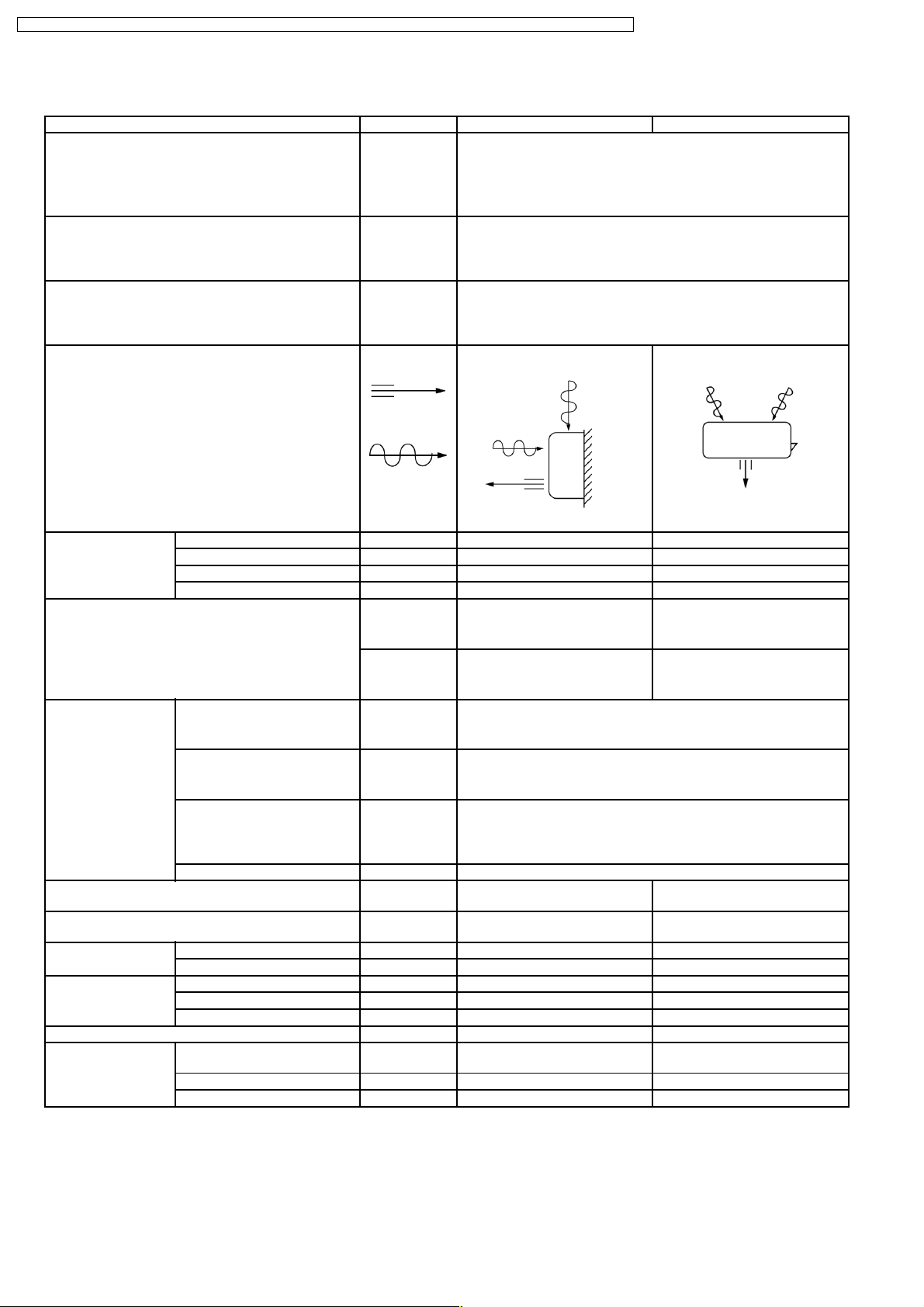
Airflow Method OUTLET
INTAKE
Air Volume Indoor Air (Lo) m3/min (cfm) 6.8 (240) - 6.8 (240) —
Indoor Air (Me) m3/min (cfm) 8.0 (280) - 8.0 (280) —
Indoor Air (Hi) m3/min (cfm) 9.9 (350) - 9.9 (350) —
Indoor Air (SHi) m3/min (cfm) 10.9 (380) - 10.9 (380) —
Noise Level dB (A) High 36 - 36, Low 26 - 26 High 47 - 46
Power level dB High 49 - 49 High 62 - 61
(1 unit) 2.82 - 2.78
2,430 - 2,390
(1 unit) 1.6
3.4
SIDE VIEW TOP VIEW
(2 units) 3.62 - 3.58
(2 units) 2.1
3,110 - 3,080
4.4
Electrical Data Input W (1 unit) 1,150 - 1,100 (2 units) 1,220 - 1,160
Running Current A (1 unit) 5.1 - 5.2 (2 units) 5.4 - 5.5
EER W/W
Starting Current A 20.5 - 19.5
Piping Connection Port
(Flare piping)
Pipe Size
(Flare piping)
Drain
Hose
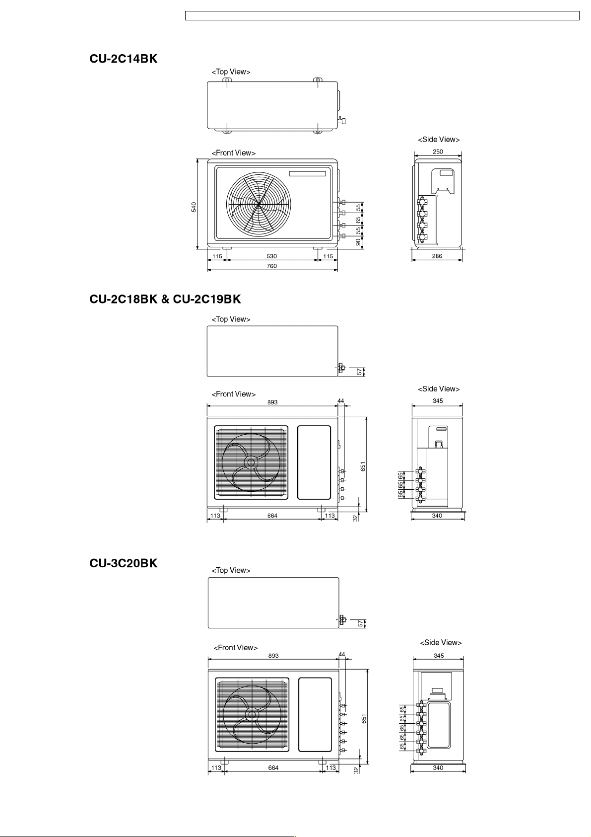
Dimensions Height inch (mm) 10 - 13/16 (275) 21 - 1/4 (540)
Net Weight lb (kg) 20 (9.0) 77 (35.0)
Compressor Type — Rotary (1 cylinder)
Inner diameter mm 12 —
Length m 0.7 —
Width inch (mm) 31 - 15/32 (799) 29 - 15/16 (760)
Depth inch (mm) 8 - 9/32 (210) 9 - 7/8 (250)
Motor Type — Induction (2-poles)
Rated Output W — 900
kcal/hW
inch
inch
inch
inch
(1 unit) 2.45 - 2.53
2.11 - 2.17
G ; Half Union 3/8”
L ; Half Union 1/4”
G (gas side) ; 3/8”
L (liquid side) ; 1/4”
(2 units) 2.97 - 3.09
2.55 - 2.66
G ; 3-way valve 3/8”
L ; 3-way valve 1/4”
G (gas side) ; 3/8”
L (liquid side) ; 1/4”
rolling piston type
6

CS-C9BKPG CU-2C14BKP5G / CS-C9BKPG CU-2C18BKP5G / CS-C9BKPG CU-3C20BKP5G / CS-C7BKPG CU-2C19BKP5G / CS-C12BKPG
Air Circulation Type Cross-flow Fan Propeller Fan
Material AS + Glass Fiber 20% AS + Glass Fiber 20%
Motor Type Induction (4-poles) Induction (6-poles)
Input W 29.3 - 26.3 41.75 - 36.80
Rated Output W 15 12
Fan Speed Low rpm 780 - 780 —
Medium rpm 920 - 920 —
High rpm 1,140 - 1,140 795 - 750
SuperHigh rpm 1,250 - 1,250 —
Heat Exchanger Description Evaporator Condenser
Tube material Copper Copper
Fin material Aluminium Aluminium
Fin Type Slit Fin Louver Fin
Row / Stage (Plate fin configuration, forced draft)
2×15 1×20
FPI 19 19
Size (W × H × L) mm 610 × 315 × 25.4 687 × 508 × 22
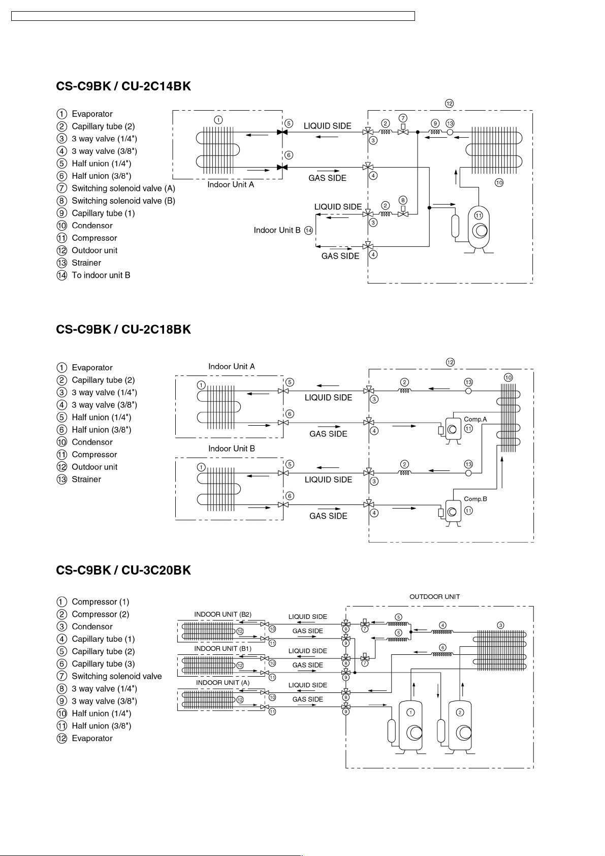
Refrigerant Control Device — Capillary Tube
Refrigeration Oil (c.c) — SUNISO 4GDID or ATMOS M60
Refrigerant (R-22) g (oz) — 890 (31.4)
Thermostat Electronic Control —
Protection Device — Overload Protector
Capillary Tube Length mm — 505
Flow Rate l/min — 17.8
Inner Diameter mm — 1.7
Air Filter Material
Style
Capacity Control Capillary Tube
Compressor Capacitor µF, VAC — 30 µF, 440 VAC
Fan Motor Capacitor µF, VAC 1.5 µF, 400 VAC 1.0 µF, 430 VAC
(c.c) P.P.
Honeycomb
(350)
—
•
Specifications are subject to change without notice for further improvement.
7
CS-C9BKPG CU-2C14BKP5G / CS-C9BKPG CU-2C18BKP5G / CS-C9BKPG CU-3C20BKP5G / CS-C7BKPG CU-2C19BKP5G / CS-C12BKPG
Unit CS-C9BKPG CU-2C18BKP5G
Power Source Phase Single
V Europe: 230 - 220 Oceania: 240 - 220
Cycle 50
Cooling Capacity kW
kcal/h
Moisture Removal l/h
Pint/h
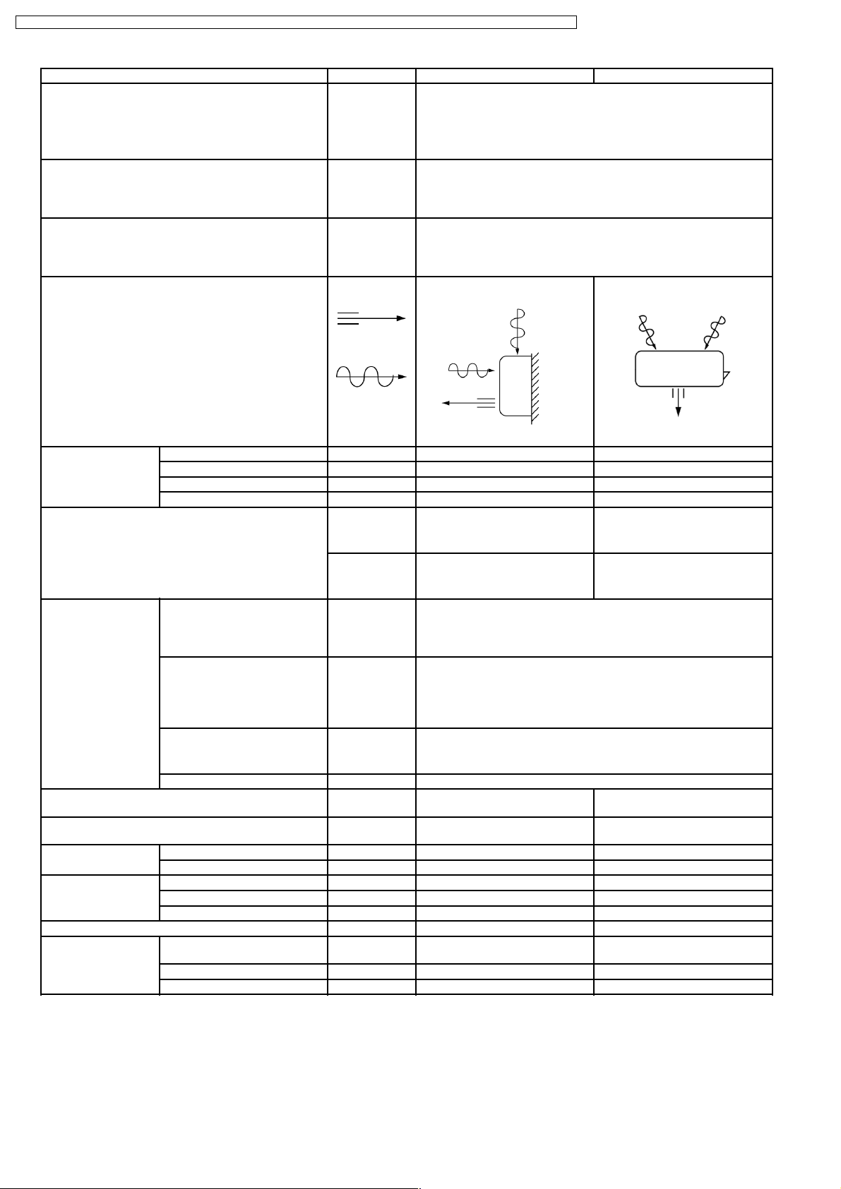
Airflow Method OUTLET
(1 unit) 2.44 - 2.40
(2 units) 4.88 - 4.80
2,100 - 2,060
(1 unit) 1.5
(2 units) 2.6
3.2
SIDE VIEW TOP VIEW
4,200 - 4,130
5.5
INTAKE
Air Volume Indoor Air (Lo) m3/min (cfm) 6.8 (240) - 6.8 (240) —
Indoor Air (Me) m3/min (cfm) 8.0 (280) - 8.0 (280) —
Indoor Air (Hi) m3/min (cfm) 9.9 (350) - 9.9 (350) —
Indoor Air (SHi) m3/min (cfm) 10.9 (380) - 10.9 (380) —
Noise Level dB (A) High 36 - 36, Low 26 - 26 High 55 - 53
Power level dB High 49 - 49 High 70 - 68
Electrical Data Input W (1 unit)
770 - 730
Running Current A (1 unit)
Europe: 3.4 - 3.5
Oceania: 3.3 - 3.5
(2 units)
1,540 - 1,460
(2 units)
Europe: 6.8 - 7.0
Oceania: 6.6 - 7.0
EER W/W (kcal/hW) 3.17 - 3.29 (2.73 - 2.83)
Starting Current A 15.5 - 15.0
Piping Connection Port
(Flare piping)
Pipe Size
(Flare piping)
Drain
Hose
Inner diameter mm 12 —
Length m 0.7 —
inch
inch
inch
inch
G ; Half Union 3/8”
L ; Half Union 1/4”
G (gas side) ; 3/8”
L (liquid side) ; 1/4”
G ; 3-way valve 3/8”
L ; 3-way valve 1/4”
G (gas side) ; 3/8”
L (liquid side) ; 1/4”
Dimensions Height inch (mm) 10 - 13/16 (275) 25 - 21/32 (651)
Width inch (mm) 31 - 15/32 (799) 35 - 3/16 (893)
Depth inch (mm) 8 - 9/32 (210) 13 - 19/32 (345)
Net Weight lb (kg) 20 (9.0) 137 (62)
Compressor Type — Rotary (1 cylinder)
rolling piston type
Motor Type — Induction (2-poles)
Rated Output W — 650
8
CS-C9BKPG CU-2C14BKP5G / CS-C9BKPG CU-2C18BKP5G / CS-C9BKPG CU-3C20BKP5G / CS-C7BKPG CU-2C19BKP5G / CS-C12BKPG
Air Circulation Type Cross-flow Fan Propeller Fan
Material AS + Glass Fiber 20% AS + Glass Fiber 20%
Motor Type Induction (4-poles) Induction (6-poles)
Input W 29.3 - 26.3 117.1 - 103.3
Rated Output W 15 43
Fan Speed Low rpm 780 - 780 —
Medium rpm 920 - 920 —
High rpm 1,140 - 1,140 760 - 720
SuperHigh rpm 1,250 - 1,250 —
Heat Exchanger Description Evaporator Condenser
Tube material Copper Copper
Fin material Aluminium Aluminium
Fin Type Slit Fin Louver Fin
Row / Stage (Plate fin configuration, forced draft)
2 × 15 2 × 24
FPI 19 16
Size (W × H × L) mm 610 × 315 × 25.4 560 × 609.6 × 44
Refrigerant Control Device — Capillary Tube
Refrigeration Oil (c.c) — SUNISO 4GDID or ATMOS M60
Refrigerant (R-22) g (oz) — 750 × 2 (26.5 × 2)
Thermostat Electronic Control —
Protection Device — Overload Protector
Capillary Tube Length mm — 680
Flow Rate l/min — 11.5
Inner Diameter mm — 1.5
Air Filter Material
Style
Capacity Control Capillary Tube
Compressor Capacitor µF, VAC — 25 µF, 370 VAC
Fan Motor Capacitor µF, VAC 1.5 µF, 400 VAC 3.0 µF, 450 VAC
(c.c) P.P.
Honeycomb
(270)
—
•
Specifications are subject to change without notice for further improvement.
9
CS-C9BKPG CU-2C14BKP5G / CS-C9BKPG CU-2C18BKP5G / CS-C9BKPG CU-3C20BKP5G / CS-C7BKPG CU-2C19BKP5G / CS-C12BKPG
CS-C9BKPG CU-3C20BKP5G
Unit
Single Operation
Single Operation Double Operation Triple
(A, B1, B2)
(A) (B1 or B2) (B1 + B2) (A + B1 or B2) (A + B1 + B2)
Power Source Phase Single
V Europe: 230 - 220 Oceania: 240 - 220
Cycle 50
Operation
Cooling Capacity Per Unit kW
— 2.40-2.34
kcal/h
Moisture Removal l/h
— 1.5
Pint/h
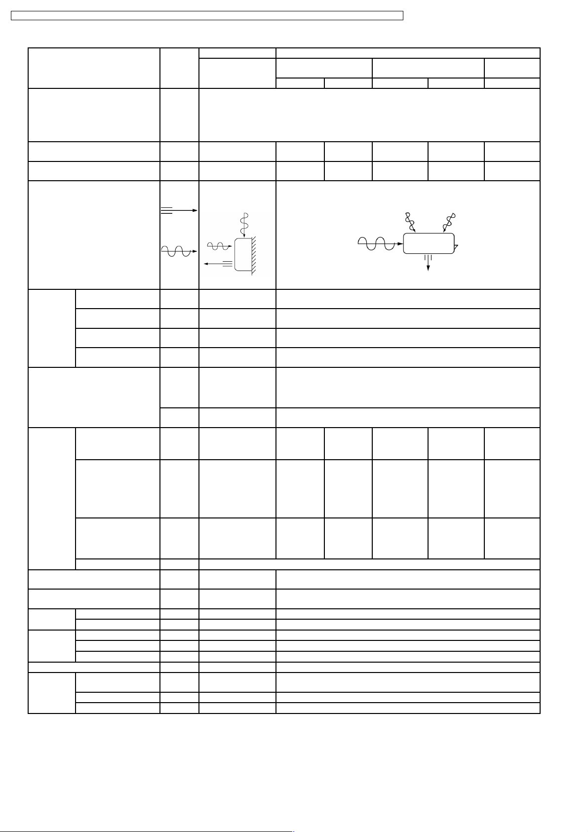
Airflow Method OUTLET
SIDE VIEW TOP VIEW
INTAKE
Air Volume Indoor Air (Lo) m3/min
(cfm)
Indoor Air (Me) m3/min
(cfm)
Indoor Air (Hi) m3/min
(cfm)
Indoor Air (SHi) m3/min
(cfm)
6.8 - 6.8
(240 - 240)
8.0 - 8.0
(280 - 280)
9.9 - 9.9
(350 - 350)
10.9 - 10.9
(380 - 380)
Noise Level dB (A) High 36 - 36,
Low 26 - 26
Power
High 49 - 49 High 71 - 69
level dB
2,060-2,010
3.2
2.82-2.78
2,430-2,390
1.6
3.4
3.60-3.52
3,100-3,030
2.1
4.4
—
—
—
—
High 56 - 54
5.22-5.12
4,490-4,400
2.8
5.9
6.00-5.86
5,160-5,040
3.2
6.8
Electrical
Input W 50 - 50 820-770 1,120-1,070 1,210-1,150 1,850-1,750 1,920-1,840
Data
Running Current A
EER W/W
(kcal/hW)
0.23 - 0.23 3.6 - 3.7
— 2.93 - 3.04
(2.51 - 2.61)
Europe:
5.0 - 5.1
Oceania:
4.9 - 5.1
2.52 - 2.60
(2.17 - 2.23)
Europe:
5.4 - 5.5
Oceania:
5.3 - 5.5
2.98 - 3.06
(2.56 - 2.63)
Starting Current A (A unit) 15.5 - 15.0 (B unit) 21.5 - 21.0
Piping Connection Port
(Flare piping)
Pipe Size
(Flare piping)
Drain
Hose
Inner diameter mm 12 —
Length m 0.7 —
inch
inch
inch
inch
G ; Half Union 3/8”
L ; Half Union 1/4”
G (gas side) ; 3/8”
L (liquid side) ; 1/4”
G;3-wayvalve3/8”
L ; 3-way valve 1/4”
G (gas side) ; 3/8”
L (liquid side) ; 1/4”
Dimensions Height inch (mm) 10 - 13/16 (275) 25 - 21/32 (651)
Width inch (mm) 31 - 15/32 (799) 35 - 3/16 (893)
Depth inch (mm) 8 - 9/32 (210) 13 - 19/32 (345)
Net Weight lb (kg) 20 (9.0) 146 (66)
Compressor Type — Rotary (1 cylinder)
rolling piston type
Motor Type — Induction (2-poles)
Rated Output W — (A unit) 650 (B unit) 900
8.1 - 8.3
2.82 - 2.93
(2.43 - 2.51)
Europe:
8.4 - 8.7
Oceania:
8.3 - 8.7
3.13 - 3.18
(2.69 - 2.74)
10
CS-C9BKPG CU-2C14BKP5G / CS-C9BKPG CU-2C18BKP5G / CS-C9BKPG CU-3C20BKP5G / CS-C7BKPG CU-2C19BKP5G / CS-C12BKPG
Air
Circulation
Motor Type Induction (4-poles) Induction (6-poles)
Rated Output W 15 37
Fan Speed Low rpm 780 - 780 —
Heat
Exchanger
Refrigerant Control Device — Capillary Tube
Refrigeration Oil (c.c) — SUNISO 4GDID or ATMOS M60 (320, 270)
Refrigerant (R-22) g (oz) — (A unit) 800 (28.2)
Thermostat Electronic Control —
Protection Device — Overload Protector
Capillary
Tube
Air Filter Material
Capacity Control Capillary Tube
Compressor Capacitor µF, VAC — 25 µF, 440 VAC
Fan Motor Capacitor µF, VAC 1.5 µF, 400 VAC 3.0 µF, 450 VAC
Description Evaporator Condenser
Tube material Copper Copper
Fin material Aluminium Aluminium
Fin Type Slit Fin Louver Fin
Row / Stage (Plate fin configuration, forced draft)
FPI 19 16
Size (W × H × L) mm 610 × 315 × 25.4 756.0
Length mm — 935, 920, 1,170
Flow Rate l/min — 20.0, 15.5, 10.0
Inner Diameter mm — 2.0, 1.8, 1.6
Style
Type Cross-flow Fan Propeller Fan
Material AS + Glass Fiber
20%
Input W 29.3 - 26.3 121.82 - 107.91
Medium rpm 920 - 920 —
High rpm 1,140 - 1,140 765 - 725
SuperHigh rpm 1,250 - 1,250 —
2 × 15 2 × 24
P.P.
Honeycomb
AS + Glass Fiber 20%
× 609.6 × 44
719.5
(B unit) 1,070 (37.7)
—
•
Specifications are subject to change without notice for further improvement.
11
CS-C9BKPG CU-2C14BKP5G / CS-C9BKPG CU-2C18BKP5G / CS-C9BKPG CU-3C20BKP5G / CS-C7BKPG CU-2C19BKP5G / CS-C12BKPG
Unit
Cooling Capacity kW
kcal/h
Moisture Removal l/h
Pint/h
Power Source Phase
V
Cycle
Airflow Method OUTLET
One Unit (A)
CS-C12BKPG
(A) 3.55 - 3.52
(A) 3,050 - 3,030
(A) 2.1
4.4
SIDE VIEW TOP VIEW
One Unit (B)
CS-C7BKPG
(B) 2.08 - 2.06
(B) 1,790 - 1,770
(B) 1.4
3.0
Single
230 - 220
50
CU-2C19BKP5G
(A+B) 5.63 - 5.58
(A+B) 4,840 - 4,800
(A+B) 3.1
6.6
INTAKE
Air Volume Indoor Air (Lo) m3/min (cfm) 7.3 - 7.3 (260 - 260) 6.4 - 6.4 (230 - 230) —
Indoor Air (Me) m3/min (cfm) 8.7 - 8.7 (310 - 310) 7.4 - 7.4 (260 - 260) —
Indoor Air (Hi) m3/min (cfm) 10.2 - 10.2 (360 - 360) 8.5 - 8.5 (300 - 300) —
Indoor Air (SHi) m3/min (cfm) 10.5 - 10.5 (370 - 370) 9.4 - 9.4 (330 - 330) —
Noise Level dB (A) (A) High 39 - 39
Low 29 - 29
Power level
(A) High 52 - 52 (B) High 46 - 46 High 70 - 68
(B) High 33 - 33
Low 26 - 26
High 55 - 53
dB
Electrical Data Input W (A) 1,250 - 1,230 (B) 750 - 720 (A+B) 1,880 -1,840
Running Current A (A) 5.7 - 5.9 (B) 3.9 - 3.8 (A+B) 9.0 - 9.1
EER W/W
(kcal/hW)
(A) 2.84 - 2.86
(2.44 - 2.46)
(B) 2.77 - 2.86
(2.39 - 2.46)
(A+B) 2.99 - 3.03
(2.57 - 2.61)
Starting Current A (A) 25 - 24 (B) 15 - 14 (A+B) 40 - 38
Piping Connection Port
(Flare piping)
Pipe Size
(Flare piping)
Drain
Hose
Inner diameter mm 12 —
Length m 0.7 —
inch
inch
inch
inch
G ; Half Union 1/2”,3/8”
L ; Half Union 1/4”, 1/4”
G (gas side) ; 1/2”,3/8”
L (liquid side) ; 1/4”, 1/4”
G ; 3-way valve 1/2”,3/8”
L ; 3-way valve 1/4”,1/4”
G (gas side) ; 1/2”,3/8”
L (liquid side) ; 1/4”,1/4”
Dimensions Height inch (mm) 10 - 13/16 (275) 25 - 21/32 (651)
Width inch (mm) 31 - 15/32 (799) 35 - 3/16 (893)
Depth inch (mm) 8 - 9/32 (210) 13 - 19/32 (345)
Net Weight lb (kg) 20 (9.0) 148 (67)
Compressor Type — Rotary (1 cylinder)
rolling piston type
Motor Type — Induction (2-poles)
Rated Output W (A) 1,100 (B) 600 (A+B) 1,700
Air Circulation Type Cross-flow Fan Propeller Fan
Material AS + Glass Fiber 20% AS + Glass Fiber 20%
Motor Type Induction (4-poles) Induction (6-poles)
Input W (A) 28.7 - 27.1 (B) 20.6 - 19.1 121.82 - 107.91
Rated Output W (A) 15 (B) 10 37
Fan Speed Low rpm (A) 900 - 900 (B) 780 - 780 —
Medium rpm (A) 1,080 - 1,080 (B) 900 - 900 —
High rpm (A) 1,260 - 1,260 (B) 1,030 - 1,030 740 - 725
SuperHigh rpm (A) 1,300 - 1,300 (B) 1,140 - 1,140 —
12
CS-C9BKPG CU-2C14BKP5G / CS-C9BKPG CU-2C18BKP5G / CS-C9BKPG CU-3C20BKP5G / CS-C7BKPG CU-2C19BKP5G / CS-C12BKPG
Heat Exchanger Description Evaporator Condenser
Tube material Copper Copper
Fin material Aluminium Aluminium
Fin Type Slit Fin Louver Fin
Row / Stage (Plate fin configuration, forced draft)
(A) 2 × 15 (B) 2 × 15 2 × 24
FPI 21 19 16
Size (W × H × L) mm 610 × 315 × 25.4 756
Refrigerant Control Device — Capillary Tube
Refrigeration Oil (c.c) — SUNISO 4GDID or ATMOS
Refrigerant (R-22) g (oz) — (A) 840 (29.7)
Thermostat Electronic Control —
Protection Device — Overload Protector
Capillary Tube Length mm — (A) 610 (B) 920
Flow Rate l/min — (A) 16.5 (B) 9.5
Inner Diameter mm — (A) 1.7 (B) 1.5
Air Filter Material
Style
Capacity Control Capillary Tube
Compressor Capacitor µF, VAC — (A) 30 µF, 370 VAC
Fan Motor Capacitor µF, VAC 1.5 µF, 400 VAC 3.0 µF, 450 VAC
(c.c) P.P.
Honeycomb
× 609.6 × 44
719.5
M60 (290, 410)
(B) 820 (28.9)
—
(B) 1 5 µF, 440 VAC
•
Specifications are subject to change without notice for further improvement.
13
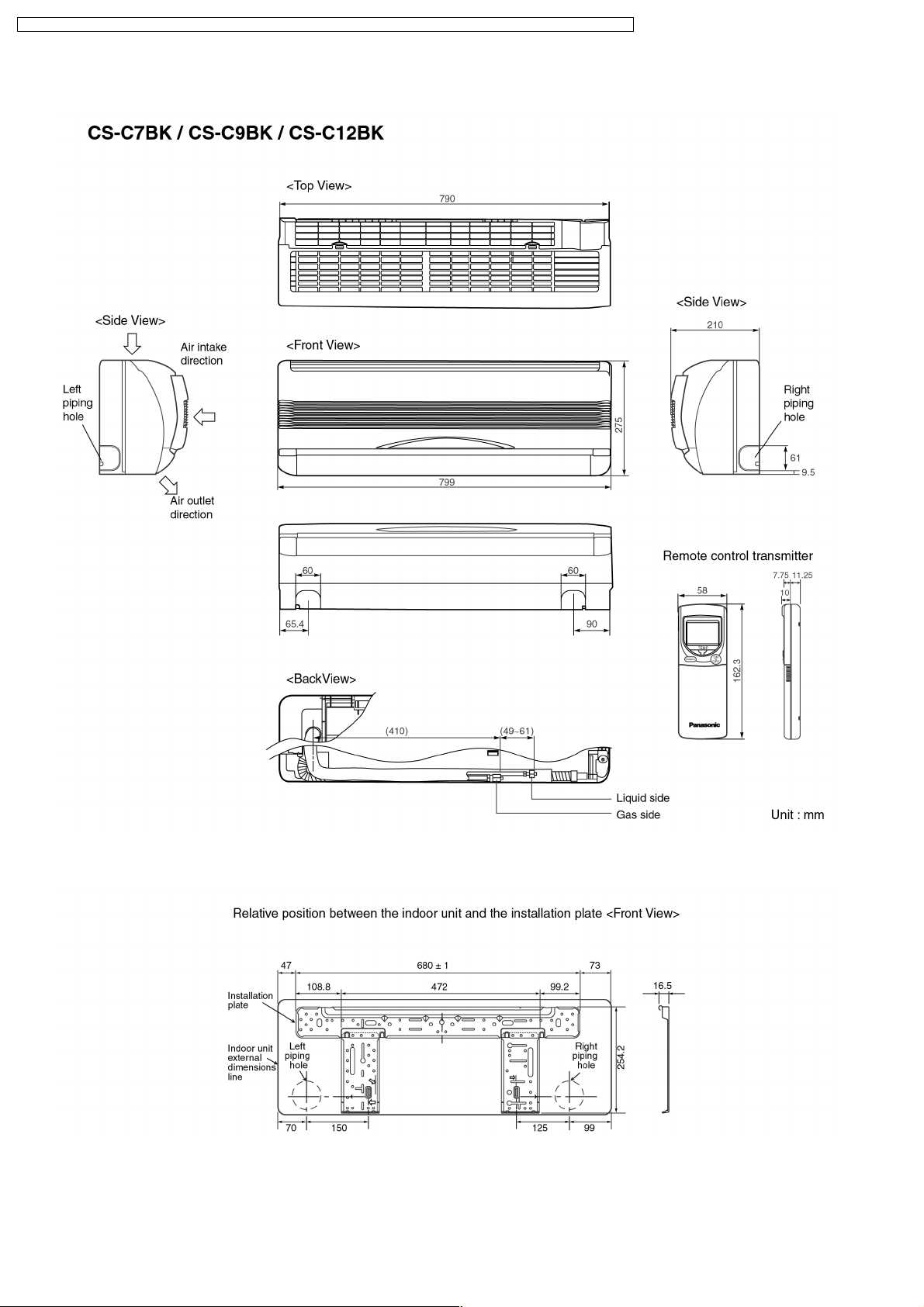
CS-C9BKPG CU-2C14BKP5G / CS-C9BKPG CU-2C18BKP5G / CS-C9BKPG CU-3C20BKP5G / CS-C7BKPG CU-2C19BKP5G / CS-C12BKPG
4 Dimensions
14
CS-C9BKPG CU-2C14BKP5G / CS-C9BKPG CU-2C18BKP5G / CS-C9BKPG CU-3C20BKP5G / CS-C7BKPG CU-2C19BKP5G / CS-C12BKPG
15
CS-C9BKPG CU-2C14BKP5G / CS-C9BKPG CU-2C18BKP5G / CS-C9BKPG CU-3C20BKP5G / CS-C7BKPG CU-2C19BKP5G / CS-C12BKPG
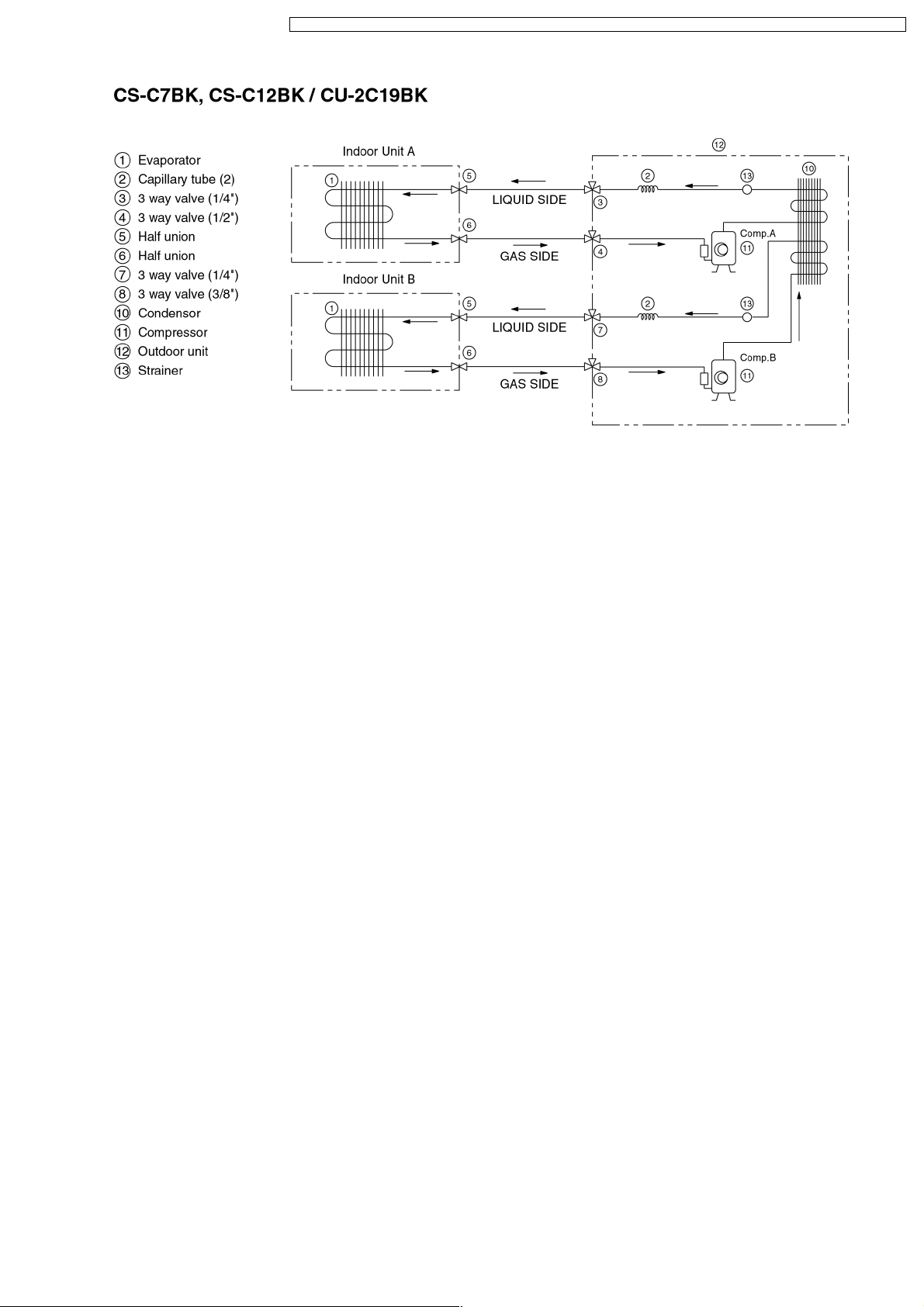
5 Refrigeration Cycle Diagram
16
CS-C9BKPG CU-2C14BKP5G / CS-C9BKPG CU-2C18BKP5G / CS-C9BKPG CU-3C20BKP5G / CS-C7BKPG CU-2C19BKP5G / CS-C12BKPG
17
CS-C9BKPG CU-2C14BKP5G / CS-C9BKPG CU-2C18BKP5G / CS-C9BKPG CU-3C20BKP5G / CS-C7BKPG CU-2C19BKP5G / CS-C12BKPG
6 Block Diagram
18
CS-C9BKPG CU-2C14BKP5G / CS-C9BKPG CU-2C18BKP5G / CS-C9BKPG CU-3C20BKP5G / CS-C7BKPG CU-2C19BKP5G / CS-C12BKPG
19
CS-C9BKPG CU-2C14BKP5G / CS-C9BKPG CU-2C18BKP5G / CS-C9BKPG CU-3C20BKP5G / CS-C7BKPG CU-2C19BKP5G / CS-C12BKPG
20
CS-C9BKPG CU-2C14BKP5G / CS-C9BKPG CU-2C18BKP5G / CS-C9BKPG CU-3C20BKP5G / CS-C7BKPG CU-2C19BKP5G / CS-C12BKPG
21
CS-C9BKPG CU-2C14BKP5G / CS-C9BKPG CU-2C18BKP5G / CS-C9BKPG CU-3C20BKP5G / CS-C7BKPG CU-2C19BKP5G / CS-C12BKPG
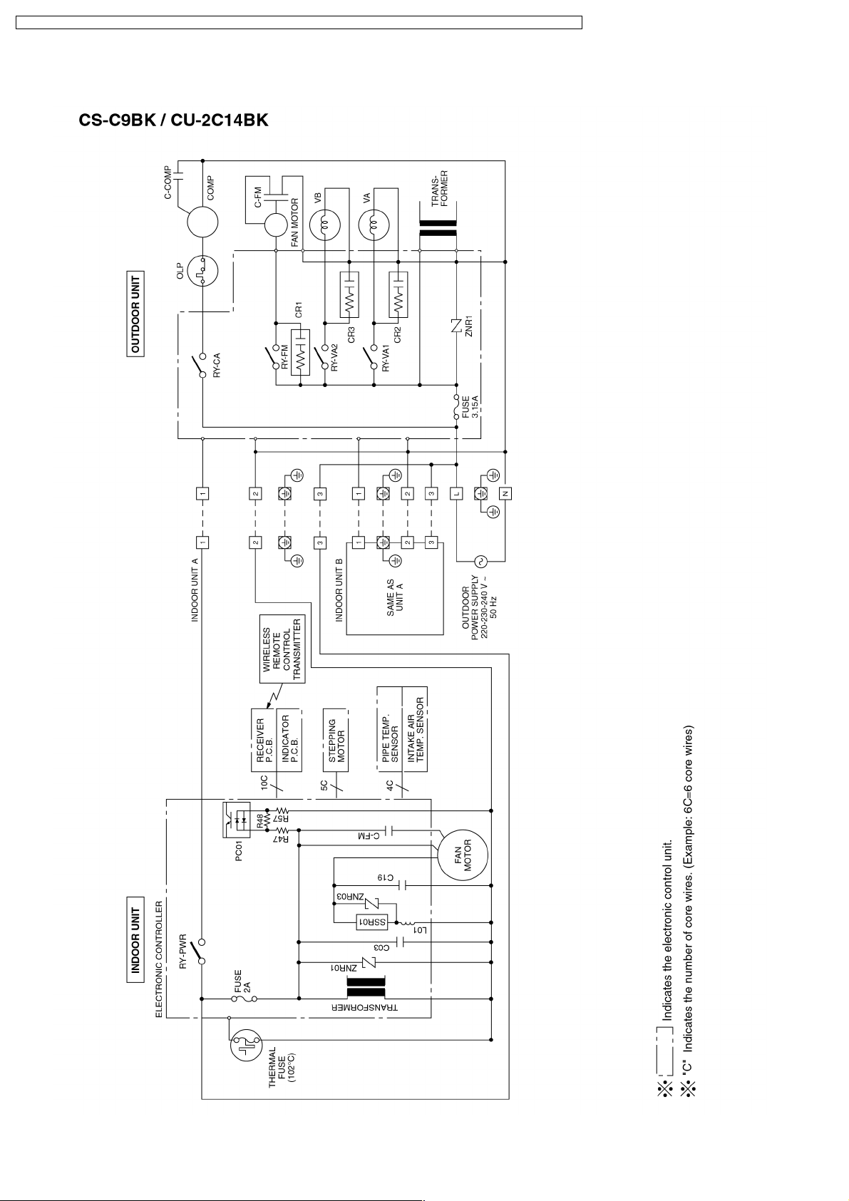
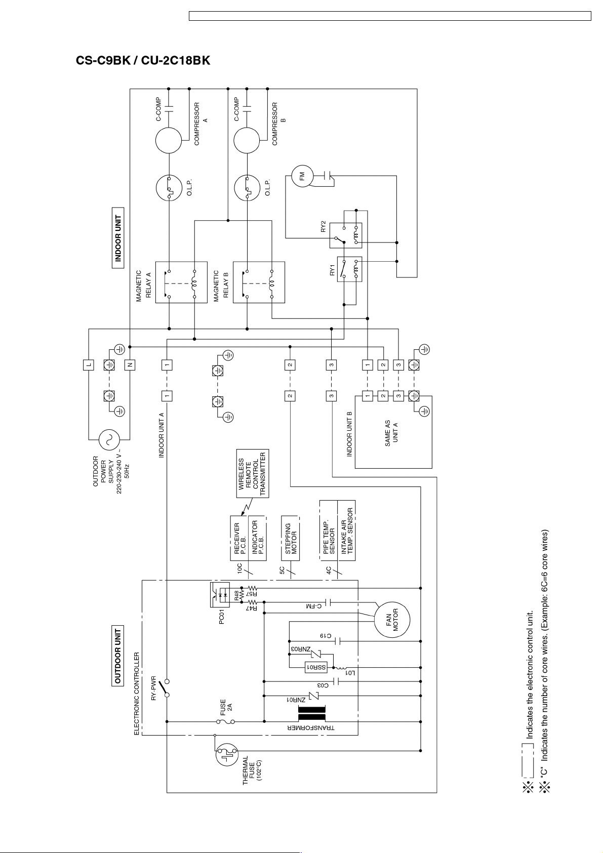
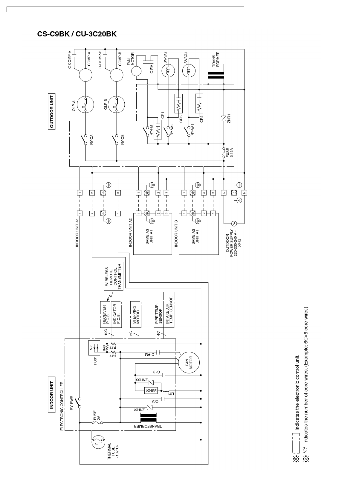
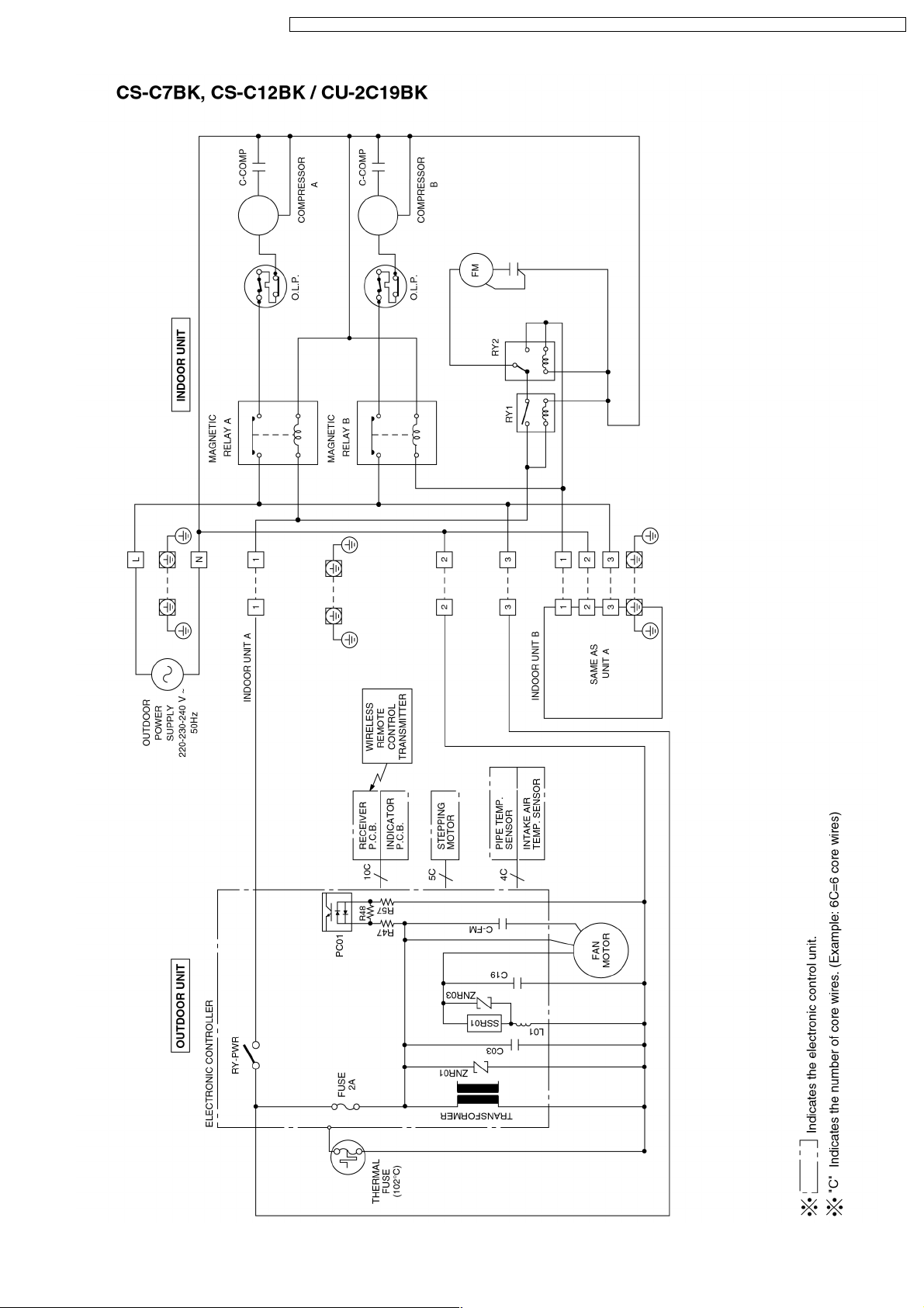
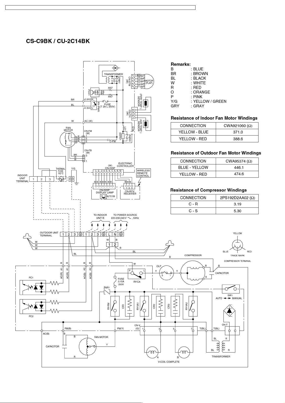
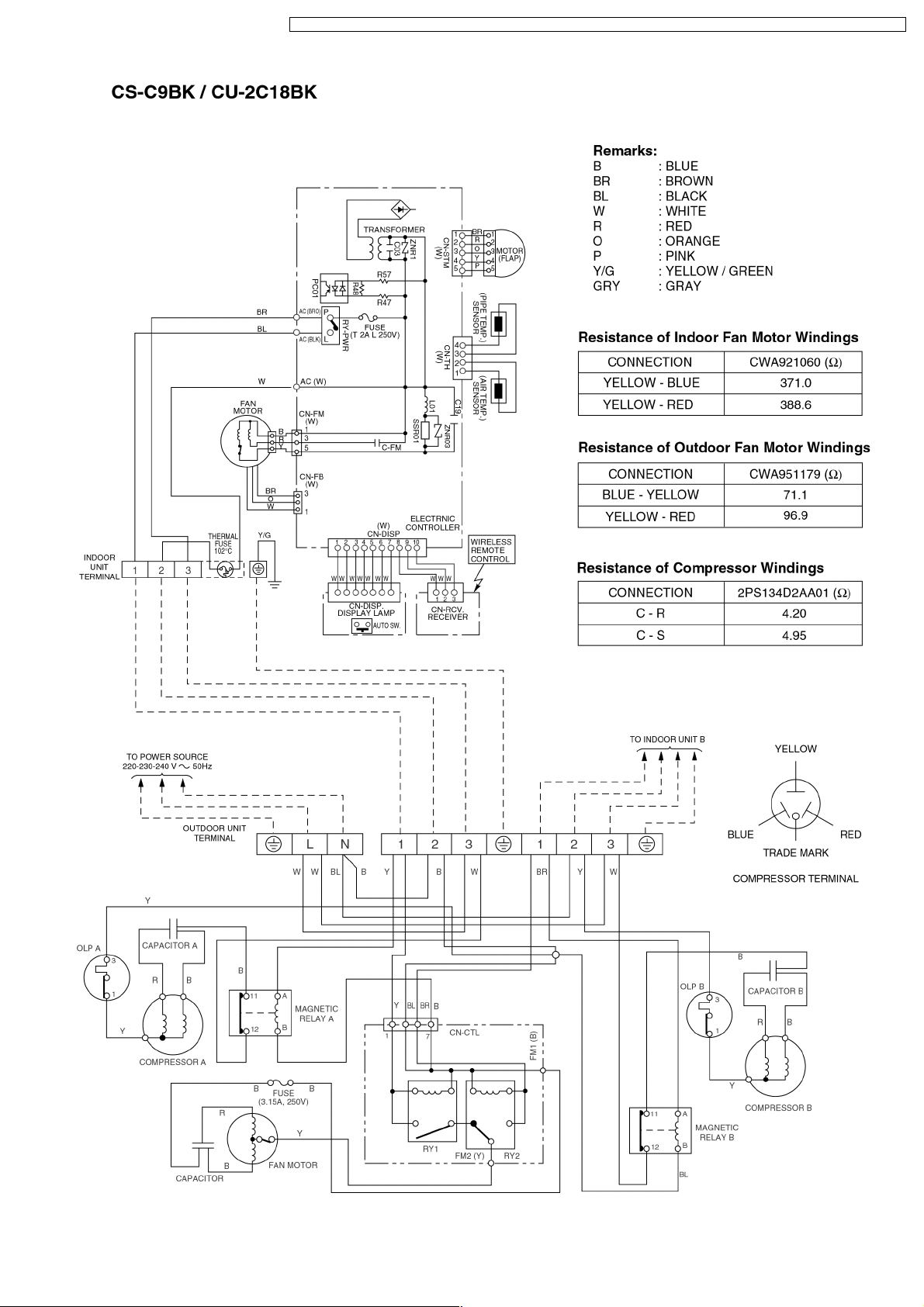
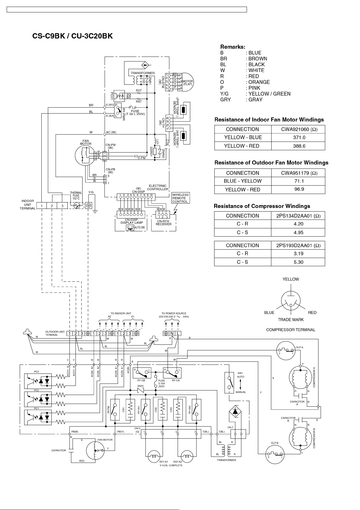
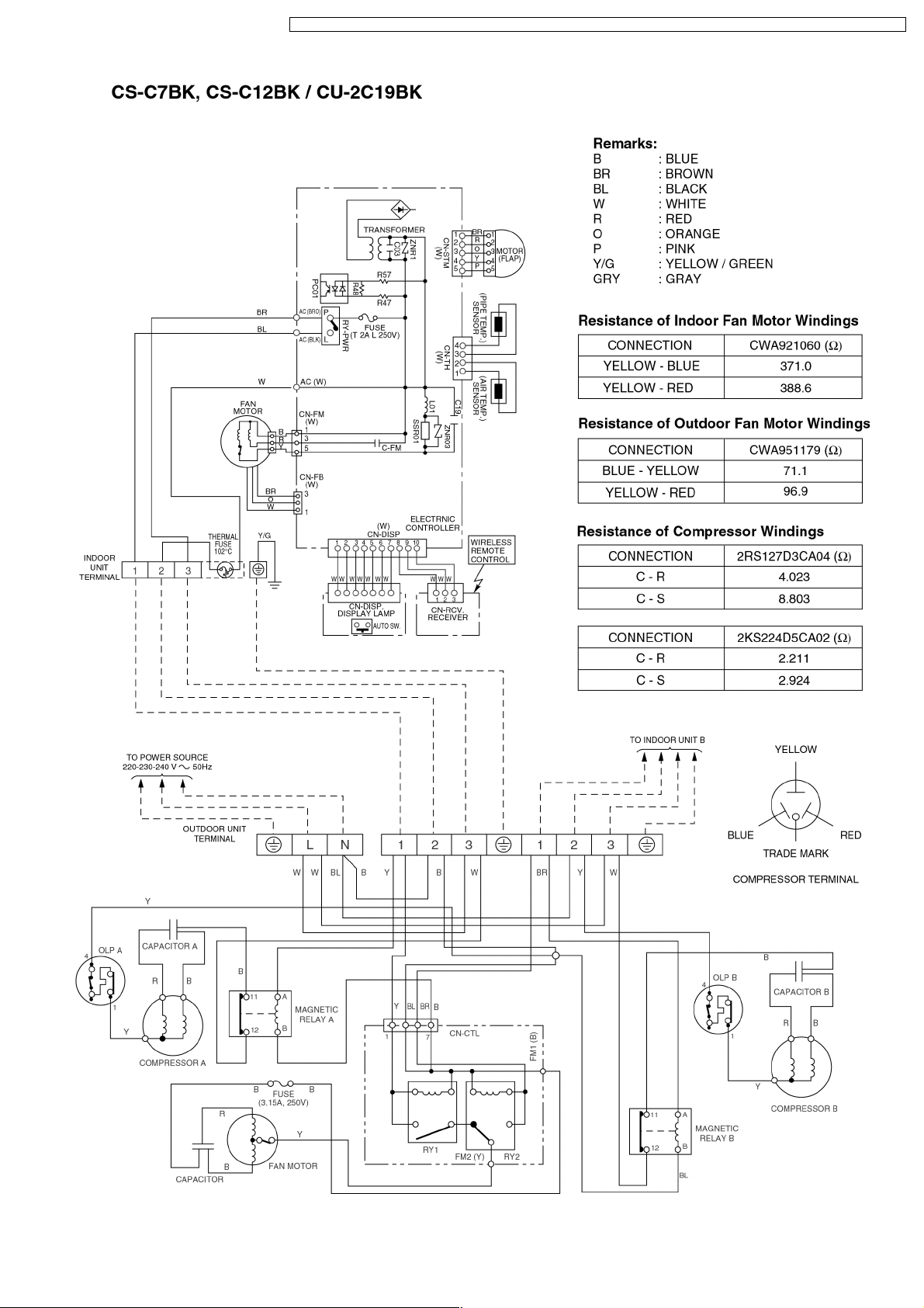
7 Wiring Diagram
22
CS-C9BKPG CU-2C14BKP5G / CS-C9BKPG CU-2C18BKP5G / CS-C9BKPG CU-3C20BKP5G / CS-C7BKPG CU-2C19BKP5G / CS-C12BKPG
23
CS-C9BKPG CU-2C14BKP5G / CS-C9BKPG CU-2C18BKP5G / CS-C9BKPG CU-3C20BKP5G / CS-C7BKPG CU-2C19BKP5G / CS-C12BKPG
24
CS-C9BKPG CU-2C14BKP5G / CS-C9BKPG CU-2C18BKP5G / CS-C9BKPG CU-3C20BKP5G / CS-C7BKPG CU-2C19BKP5G / CS-C12BKPG
25
CS-C9BKPG CU-2C14BKP5G / CS-C9BKPG CU-2C18BKP5G / CS-C9BKPG CU-3C20BKP5G / CS-C7BKPG CU-2C19BKP5G / CS-C12BKPG
8 Operation Details
8.1. Cooling Mode Operation
Cooling in operation according to Remote Control setting.
Time Delay Safety Control (3 minutes)
When the compressor is stopped by Remote Control, it restarts after 3 minutes when the Remote Control is turned ON.
•
When the setting temperature is reached during cooling operation, the compressor stops and it will not start for 3 minutes.
•
7 minutes Time Save Control
The compressor will start automatically if it has stopped for 7 minutes even if the room temperature is between the compressor
•
ON temperature and OFF temperature.
Starting Current Control
When the compressor outdoor fan motor and indoor fan motor are simultaneously started, the indoor fan motor will operate 1.6
•
second later.
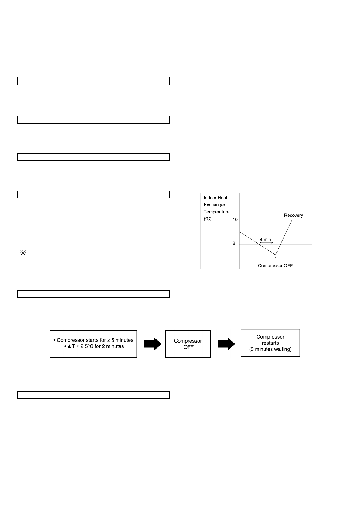
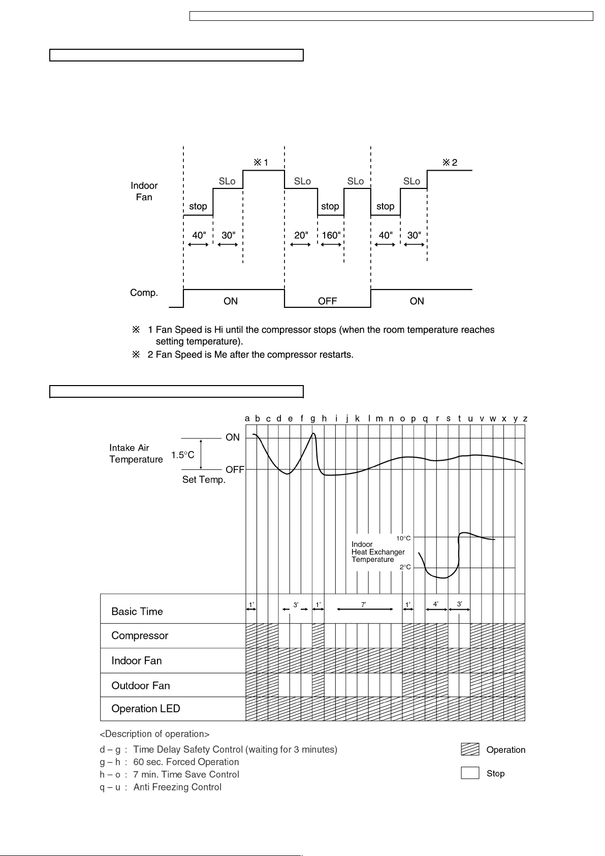
Anti-Freezing Control
If the temperature of the indoor heat exchanger falls
•
continuously below 2°C for 4 minutes or more, the
compressor turns off to protect the indoor heat exchanger
from freezing. The fan speed setting remains the same.
Compressor will restart again when the indoor heat
•
exchanger temperature rises to 10°C (Recovery).
3 minutes waiting of Time Delay Safety Control is valid for
Cooling Operation.
Compressor Reverse Rotation Protection Control
If the compressor is operating continuously for 5 minutes or longer and the temperature difference between intake air and
•
indoor heat exchanger is 2.5°C or less for 2 minutes, compressor will stop and restart automatically.
(Time Delay Safety Control is valid)
▲
T = Intake air temperature - Indoor heat exchanger temperature
This is to protect reverse rotation of the compressor when there is a instantaneous power failure.
Anti-Dew Formation Control
Purpose is to prevent dew formation on indoor unit air discharge area.
•
When the following conditions accur for 30 minutes continuously, anti-dew formation is controlled by indoor fan speed shift to
•
low (CLo to HLo):
Indoor intake air temperature is more than 24°C and less than 30°C.
−
Remote Contro l setting temperature is less than 25°C.
−
Compressor is on.
−
Cooling operation mode.
−
Indoor Fan motor operate at Low fan speed.
−
This control is cancelled immediately when above condition is changed.
•
26
CS-C9BKPG CU-2C14BKP5G / CS-C9BKPG CU-2C18BKP5G / CS-C9BKPG CU-3C20BKP5G / CS-C7BKPG CU-2C19BKP5G / CS-C12BKPG
Automatic Fan Speed Mode
When Automatic Fan Speed is selected at Remote Control during cooling operation.
Fan speed rotates in the range of Hi to Me.
•
Deodorizing Control.
•
Cooling Operation Time Diagram
27
CS-C9BKPG CU-2C14BKP5G / CS-C9BKPG CU-2C18BKP5G / CS-C9BKPG CU-3C20BKP5G / CS-C7BKPG CU-2C19BKP5G / CS-C12BKPG
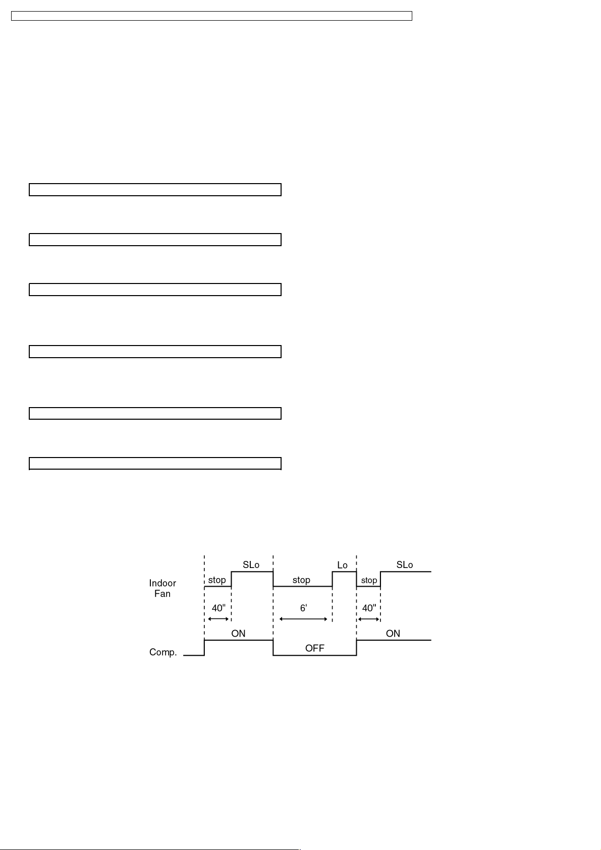
8.2. Soft Dry Mode Operation
The unit starts cooling operation until the room temperature reaches the setting temperature set on the Remote Control, and
•
then Soft Dry operation will start.
During Soft Dry operation, the Indoor Fan will operate at SLo speed.
•
The operation will be switched on and off for up to 10 minutes “ON” and 6 minutes “OFF”. Once Soft Dry operation is turned
•
off, it stops for 6 minutes.
Time Delay Safety Control
Once the compressor stops, it will not start for 3 minutes during Cooling operation.
•
Starting Current Control
Same as Starting Current Control for Cooling Mode operation.
•
Anti-Freezing Control
Same as Anti-Freezing Control for Cooling Mode operation. (For Soft Dry region, 6 minutes waiting is valid during compressor
•
stops.)
Compressor Reverse Rotation Protection Control
Same as Compressor Reverse Rotation Protection Control for Cooling Mode Operation. (For Soft Dry region, 6 minutes waiting
•
is valid during compressor stops.)
Anti-Dew Formation Control
Same as Anti-Dew Formation Control for Cooling Mode operation.
•
Automatic Fan Speed Mode
When Automatic Fan Speed is selected at Remote Control during Soft Dry operation.
Fan speed off and on at SLo speed.
•
Deodorizing Control.
•
28
 Loading...