

Panasonic CS-F4DTE5, CU-BDBE5 Service Manual

ORDER NO. MAC0509070C2
Air Conditioner
CS-F24DD3E5 CU-B24DBE5
CS-F28DD3E5 CU-B28DBE5
CS-F28DD3E5 CU-B28DBE8
CS-F34DD3E5 CU-B34DBE5
CS-F34DD3E5 CU-B34DBE8
CS-F43DD3E5 CU-B43DBE8
CS-F50DD3E5 CU-B50DBE8
CONTENTS
Page Page
1 SERVICE INFORMATION 3
1.1. Example of trouble at test operation
1.2. Caution of test operation
1.3. Caution during automatic address setting
1.4. Operation range
2 FEATURES
3
3
3
3
4
2.1. Hide-away type 4
2.2. Outdoor unit
2.3. A brand-new control method using the latest in technology
3 SPECIFICATION
© 2005 Panasonic HA Air-Conditioning (M) Sdn Bhd
(11969-T). All rights reserved. Unauthorized copying
and distribution is a violation of law.
4
5
6
3.1. CS-F24DD3E5 CU-B24DBE5 6
3.2. CS-F28DD3E5 CU-B28DBE5
3.3. CS-F28DD3E5 CU-B28DBE8
3.4. CS-F34DD3E5 CU-B34DBE5
3.5. CS-F34DD3E5 CU-B34DBE8
3.6. CS-F43DD3E5 CU-B43DBE8
3.7. CS-F50DD3E5 CU-B50DBE8
4 DIMENSIONS
4.1. CS-F24DD3E5 CS-F28DD3E5
4.2. CS-F34DD3E5 CS-F43DD3E5 CS-F50DD3E5
4.3. CU-B24DBE5 CU-B28DBE5 CU-B28DBE8
4.4. CU-B34DBE5 CU-B34DBE8 CU-B43DBE8 CUB50DBE8
5 REFRIGERATION CYCLE
5.1. CS-F24DD3E5 CU-B24DBE5 CS-F28DD3E5 CUB28DBE5 CU-B28DBE8
5.2. CS-F34DD3E5 CU-B34DBE5 CU-B34DBE8 CSF43DD3E5 CU-B43DBE8 CS-F50DD3E5 CU-B50DBE8
6 BLOCK DIAGRAM
6.1. CS-F24DD3E5 CS-F28DD3E5 CS-F34DD3E5 CSF43DD3E5 CS-F50DD3E5
6.2. CU-B24DBE5 CU-B28DBE5
6.3. CU-B34DBE5
6.4. CU-B28DBE8
6.5. CU-B34DBE8 CU-B43DBE8 CU-B50DBE8
7 WIRING DIAGRAM
7.1. CS-F24DD3E5 CS-F28DD3E5 CS-F34DD3E5 CSF43DD3E5 CS-F50DD3E5
7.2. CU-B24DBE5 CU-B28DBE5
7.3. CU-B28DBE8
7.4. CU-B34DBE5
7.5. CU-B34DBE8 CU-B43DBE8 CU-B50DBE8
8 WIRED REMOTE CONTROL OPERATING INSTRUCTIONS
8.1. Name and function of each part
8.2. Remote control - display
8.3. Remote control - panel
8.4. How to set remote control day and time
8.5. How to select the timer
8.6. Daily timer setting
8.7. Weekly timer setting
9 OPERATION DETAIL
9.1. Cooling operation
7
8
9
10
11
12
13
13
14
15
16
17
17
18
19
19
19
19
20
20
21
21
22
23
24
25
26
26
27
28
29
29
30
31
33
9.2. Heating operation
9.3. Soft dry operation
9.4. Auto operation
9.5. Fan operation
9.6. Normal control
9.7. Operation control
9.8. Protection control
9.9. Test run
10 INSTALLATION INSTRUCTION
10.1. Pipe length
10.2. Position of the centre gravity
10.3. Indoor unit installation
10.4. Outdoor unit installation
10.5. Wired remote controller installation
10.6. Twin systems installation
11 INSTALLATION & SERVICING AIR CONDITIONER
11.1. Outline
11.2. Tools for installing/servicing refrigerant piping
11.3. Refrigerant piping work
11.4. Installation, transferring, servicing
12 TROUBLE SHOOTING GUIDE
12.1. For standard installation
12.2. During twin operation
12.3. During group control operation
12.4. Test operation and self diagnosis
12.5. Emergency operation
12.6. Self-diagnosis error code table
13 TECHNICAL DATA
13.1. Sound data
13.2. Sound measurement point
13.3. Discharge and suction pressure
13.4. Capacity and power consumption
13.5. Fan performance
13.6. Safety device
13.7. Operating characteristics
14 REPLACEMENT PARTS
14.1. Indoor unit
14.2. Outdoor unit
15 PRINT PATTERN
15.1. Indoor unit
15.2. Outdoor unit
33
34
34
34
34
35
36
39
41
42
42
44
45
56
67
74
75
75
76
80
82
86
86
88
90
91
94
95
97
97
103
104
106
129
134
135
136
136
140
147
147
148
2
1 SERVICE INFORMATION
Notice of Address setting for NEW Duct / NEW Outdoor Unit.
The new Duct Type / New Outdoor models are possible to have address setting for twin control by automatic when main
power supply is switched on.
(Manual address setting is also possible by using Dip switch on Indoor unit P.C. board.) However,
possible when made proper wiring connection and also Indoor unit should be original virgin unit
1.1. Example of trouble at test operation
If found out as following phenomenon at test operation on site, it may have possibility of wrong address setting.
Therefore, please ensure of the address setting.
1. LCD display of wired remote control had not illuminate although the main power supply switch is ‘on’.
2. LCD display had indicated as normal illumination when power supply switch is ‘on’, however outdoor unit cannot be operated.
(But, it is necessary to take 3 to 5 minutes for outdoor unit to start from the timing of remote control ON/OFF switch is ‘on’.)
3. P.C. board had memorized wrong setting information.
a. If main power supply is switched ‘on’ with the wrong connection.
b. When changing the connection or combination of units due to re-installation etc.
• When changing the system from twin control to normal one to one system.
• When making the replacement of units as master and slave etc.
this address setting is only
.
1.2. Caution of test operation
Do not touch the remote control switch and do not change any wirings for one minute when the main power supply switch is ‘on’.
(Because the unit is having automatic address setting during the first one minute.)
1.3. Caution during automatic address setting
When main power supply switch is ‘on’, the P.C. board will automatically memorized the connecting system.
Consequently, when initial power supply is ‘on’, there will not be interchangeability of units even of the same type and same
capacity unit. Therefore unable to connect the unit to another system.
1.4. Operation range
The applicable voltage range for each unit is given in “the following table”. The working voltage among the three phases must be
balanced within 3% deviation from each voltage at the compressor terminals. The starting voltage must be higher than 85% of the
rated voltage.
1.4.1. Power Supply
Model
CU-
B24DBE5
B28DBE5
B34DBE5
B28DBE8
B34DBE8
B43DBE8
B50DBE8
Unit Main Power Applicable Voltage
Phase, Volts Hz Maximum Minimum
1~220 50 242 198
1~230 50 253 207
1~240 50 264 216
3N~380 50 418 342
3N~400 50 440 360
3N~415 50 457 374
1.4.2. Indoor and Outdoor Temperature
Model 50Hz ... B24DBE5, B28DBE5, B28DBE8, B34DBE5, B34DBE8, B43DBE8, B50DBE8
Operating Hz Indoor Temp. (D.B./W.B.) (°C) Outdoor Temp. (D.B./W.B.) (°C)
Maximum Minimum Maximum Minimum
Cooling 50 32/23 21/15 43/- -10/Heating 50 27/- 16/- 24/18 -10/-
3

2 FEATURES
2.1. Hide-away type
2.1.1. Compact design
• The height has been reduced to 25 cm, the equipment can
be installed in limited spaces.
2.1.2. Versatile installation
• The indoor unit is designed in order that air will also enter
from below, for easier installation under different conditions.
2.2. Outdoor unit
2.2.1. Flexible installation in smaller
spaces
• Space-saving outdoor unit with the improvement of the
outdoor unit fan makes it possible to install the outdoor unit
into a smaller space where the conventional model cannot
be installed.
• Long pipe design with a maximum piping length of 50m.
• Additional charging of refrigerant are not required for 30m
of pipe length.
• Flexible 4-way piping.
• The equipment has two drain outlets on the right and left
side for adoption to the installation conditions in the
building.
2.1.3. Easy maintenance
• Equipped with a filter as standard. The filter can be
removed in three directions for easier maintenance.
• Centralized drain method gather multiple outdoor units’
drain pipes into a single drain pipe to make installation
easier and also improve appearance.
• Side-by-side continuous installation is possible even for
outdoor units with different capacities.
4
2.2.2. Quiet, efficient design
• A host of silencing technologies achieves super-quiet
operation.
• The noise-suppressing winglet fan is a result of new
research into vane design theory. The unique curved shape
suppresses the generation of vortexes, thus reduces air
flows noise.
• Operating efficiency is improved and energy consumption is
reduced.
2.2.3. Low ambient cooling operation
• The unit can set for cooling even when the outdoor
temperature drops to -10°C. This is ideal for locations that
require cooling even in winter.
2.3. A brand-new control method using the latest in technology
2.3.1. Twin operation
• Simultaneous air conditioning of wide spaces and corners is
possible. Indoor units of same horsepowers and models
can even be used in combination.
• Master unit and slave-units can be set automatically in twin
systems. No address setting is necessary.
• Multiple indoor units can be operated simultaneously with a
single remote control. Note that individual operation is not
possible.
2.3.2. Group control equipment
5
3 SPECIFICATION
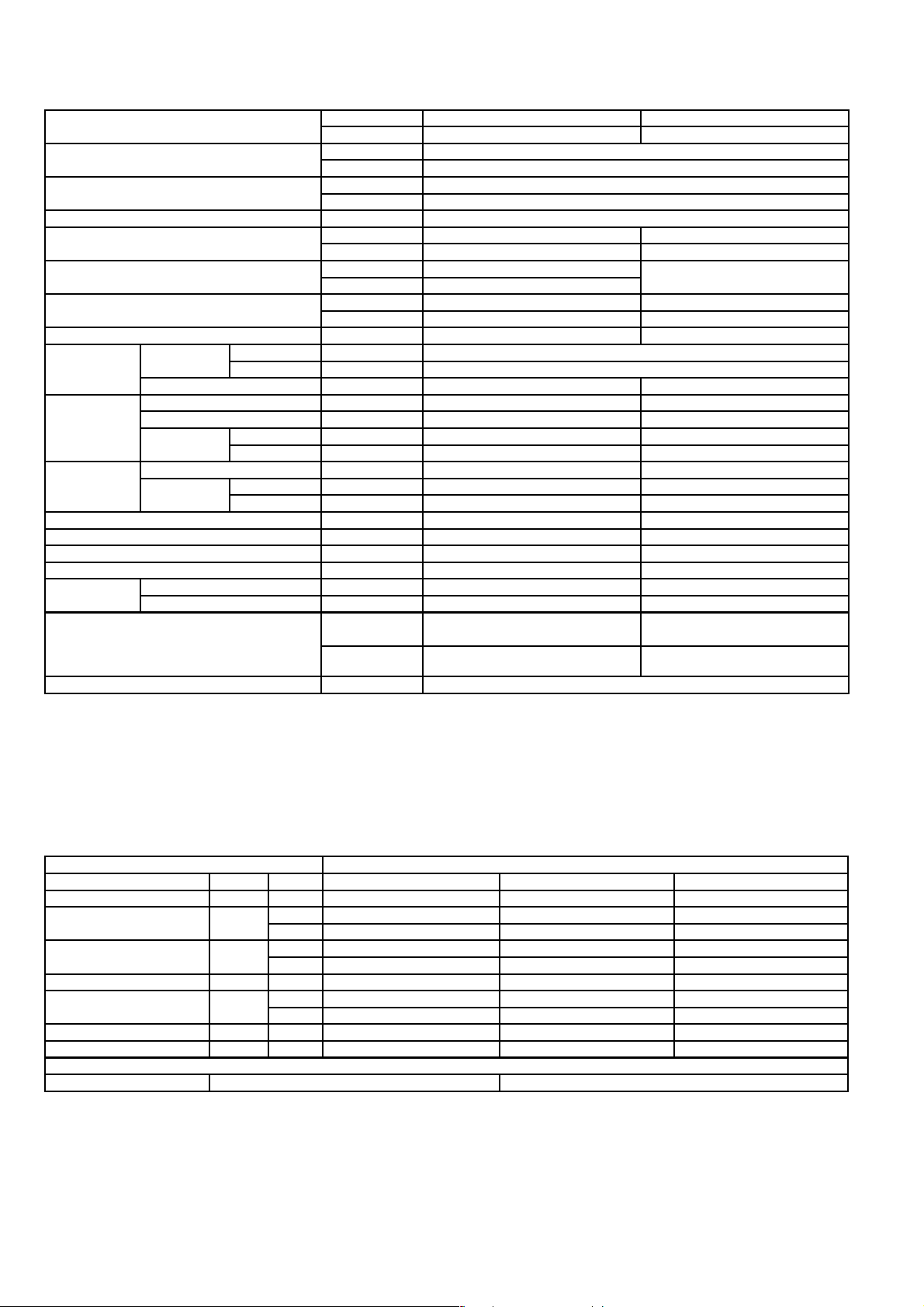
3.1. CS-F24DD3E5 CU-B24DBE5
ITEM / MODEL Indoor Unit Outdoor Unit
Main Body CS-F24DD3E5 CU-B24DBE5
Cooling Capacity kW 6.6
BTU/h 22,500
Heating Capacity kW 7.1
BTU/h 24,200
Refrigerant Charge-less m 30
Standard Air Volume for High Speed m3/min Hi 22 Hi 60
cfm Hi 777 Hi 2120
External Static Pressure Pa Hi 50 -
mmAq Hi 5.1
Outside Dimension (H x W x D) mm 250 x 1000 x 650 795 x 900 x 320
inch 9-26/32 x 39-5/16 x 25-18/32 31-5/16 x 35-7/16 x 12-19/32
Net Weight kg (lbs) 41 (91) 69 (152)
Piping
Connection
Compressor Type, Number of Set - Hermetic, 1
Fan Type, Number of Set Sirocco fan, 2 Mix flow fan - 1
Air-heat Exchanger (Row x Stage x FPI) Louvre-fin type (3 x 12 x 15) Corrugate-fin type (2 x 36 x 19)
Refrigerant Control - Exp. Valve
Refrigerant Oil (Charged) cm
Refrigerant (Charged) R410A kg (oz) - 1.7 (60)
Running
Adjustment
Noise Level dB (A) Cooling : Hi 43 Lo 39 Cooling 50, Heating 51
Moisture Removal L/h (Pt/h) 3.8 (8.0)
Refrigerant Gas mm (inch) O.D Ø 15.88 (5/8) Flared Type
Liquid mm (inch) O.D Ø 9.53 (3/8) Flared Type
Drain mm Female screw RC1 (PT1) I.D Ø 20 x 1
Starting Method - Permanent Split Capacitor
Motor Type - 2-pole single phase brushless motor
Rated Output kW - 2.2
Motor Type 4-pole single phase induction motor 6-pole single phase induction motor
Rated Output kW 0.085 0.07
3
Control Switch Wired Remote Control Room Temperature Thermostat -
Heating : Hi 43 Lo 39
Power level dB Cooling : Hi 59 Lo 55
Heating : Hi 59 Lo 55
- FV50S (1130)
Cooling 66, Heating 67
1. Cooling capacities are based on indoor temperature of 27°C D.B. (80.6°F D.B.), 19.0°C W.B. (66.2°F W.B.) and outdoor air
temperature of 35°C D.B. (95°F D.B.), 24°C W.B. (75.2°F W.B.)
2. Heating capacities are based on indoor temperature 20°C D.B. (68°F D.B.) and outdoor air temperature of 7°C D.B. (44.6°F
D.B.), 6°C W.B. (42.8°F W.B.)
ELECTRICAL DATA (50 Hz)
ITEM / MODEL Condition by ISO5151
Volts V 220 230 240
Phase Single Single Single
Power Consumption kW Cool 2.56 2.59 2.64
Heat 2.4 2.47 2.56
Running Current A Cool 12.7 12.9 13.1
Heat 11.5 11.8 12.3
Starting Current A 59 62 65
Power Factor % Cool 92 87 84
Heat 95 91 87
EER W/W 2.58 2.55 2.50
COP W/W 2.96 2.87 2.77
*Power Factor means total figure of compressor, indoor fan motor and outdoor fan motor.
Panasonic Power source AC, 1~220V, 230V, 240V 50Hz
6

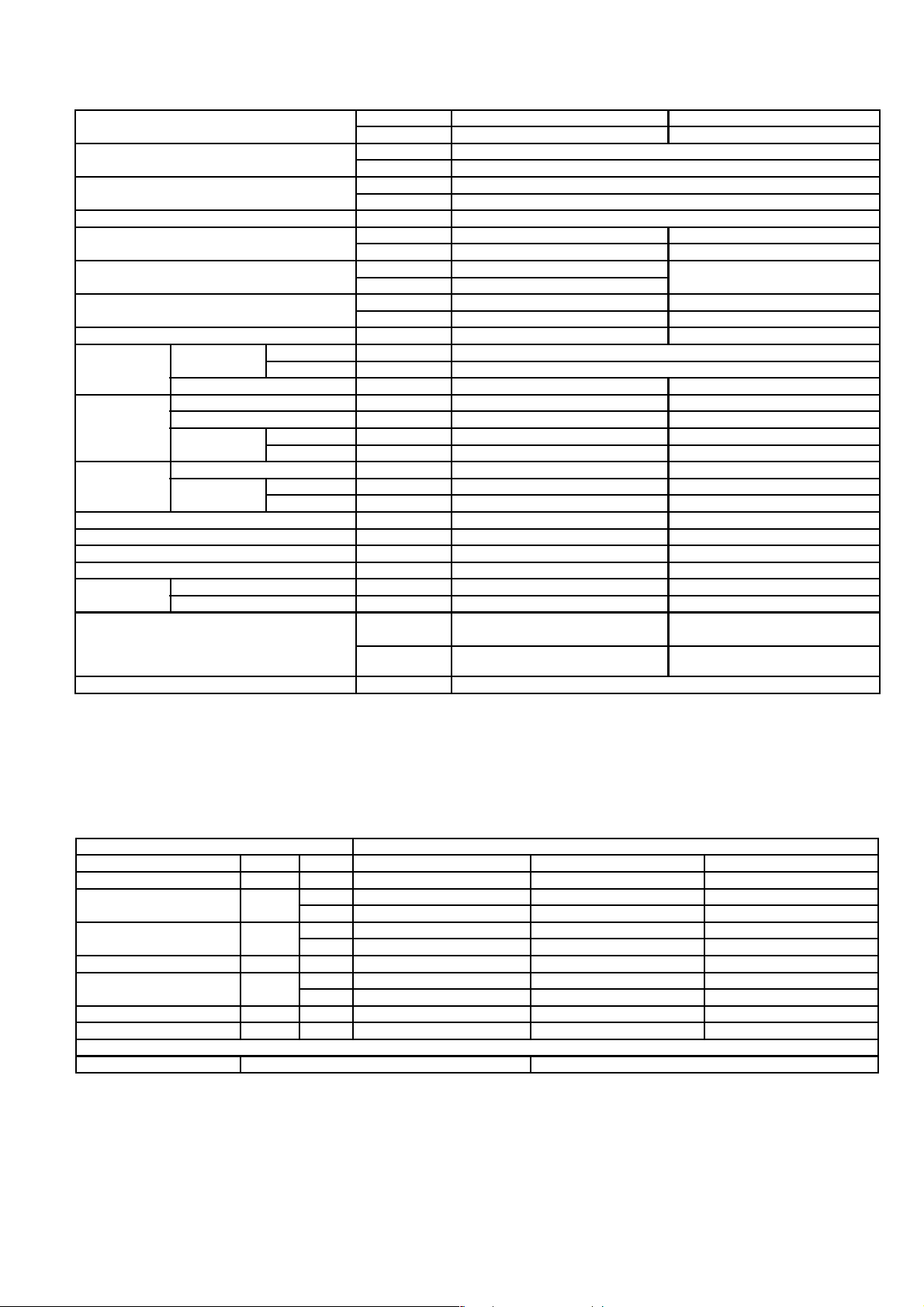
3.2. CS-F28DD3E5 CU-B28DBE5
ITEM / MODEL Indoor Unit Outdoor Unit
Main Body CS-F28DD3E5 CU-B28DBE5
Cooling Capacity kW 7.3
BTU/h 24,900
Heating Capacity kW 8.0
BTU/h 27,300
Refrigerant Charge-less m 30
Standard Air Volume for High Speed m3/min Hi 22 Hi 63
cfm Hi 777 Hi 2226
External Static Pressure Pa Hi 50 -
mmAq Hi 5.1
Outside Dimension (H x W x D) mm 250 x 1000 x 650 795 x 900 x 320
inch 9-26/32 x 39-5/16 x 25-18/32 31-5/16 x 35-7/16 x 12-19/32
Net Weight kg (lbs) 41 (91) 69 (152)
Piping
Connection
Compressor Type, Number of Set - Hermetic, 1
Fan Type, Number of Set Sirocco Fan, 2 Mix flow fan - 1
Air-heat Exchanger (Row x Stage x FPI) Louvre-fin type (3 x 12 x 15) Corrugate-fin type (2 x 36 x 19)
Refrigerant Control - Exp. Valve
Refrigerant Oil (Charged) cm
Refrigerant (Charged) R410A kg (oz) - 2.05 (72)
Running
Adjustment
Noise Level dB (A) Cooling : Hi 43 Lo 39 Cooling 52, Heating 53
Moisture Removal L/h (Pt/h) 4.3 (9.0)
Refrigerant Gas mm (inch) O.D Ø 15.88 (5/8) Flared Type
Liquid mm (inch) O.D Ø 9.53 (3/8) Flared Type
Drain mm Female screw RC1 (PT1) I.D Ø 20 x 1
Starting Method - Permanent Split Capacitor
Motor Type - 2-pole single phase brushless motor
Rated Output kW - 2.2
Motor Type 4-pole single phase induction motor 6-pole single phase induction motor
Rated Output kW 0.085 0.07
3
Control Switch Wired Remote Control Room Temperature Thermostat -
Heating : Hi 43 Lo 39
Power level dB Cooling : Hi 59 Lo 55
Heating : Hi 59 Lo 55
- FV50S (1130)
Cooling 67, Heating 68
1. Cooling capacities are based on indoor temperature of 27°C D.B. (80.6°F D.B.), 19.0°C W.B. (66.2°F W.B.) and outdoor air
temperature of 35°C D.B. (95°F D.B.), 24°C W.B. (75.2°F W.B.)
2. Heating capacities are based on indoor temperature of 20°C D.B. (68°F D.B.) and outdoor air temperature of 7°C D.B. (44.6°F
D.B.), 6°C W.B. (42.8°F W.B.)
ELECTRICAL DATA (50 Hz)
ITEM / MODEL Condition by ISO5151
Volts V 220 230 240
Phase Single Single Single
Power Consumption kW Cool 2.78 2.84 2.89
Heat 2.61 2.69 2.78
Running Current A Cool 13.3 13.5 13.7
Heat 12.5 12.6 13.1
Starting Current A 62 65 68
Power Factor % Cool 95 91 88
Heat 95 93 88
EER W/W 2.63 2.57 2.53
COP W/W 3.07 2.97 2.88
*Power Factor means total figure of compressor, indoor fan motor and outdoor fan motor.
Panasonic Power source AC, 1~220V, 230V, 240V 50Hz
7
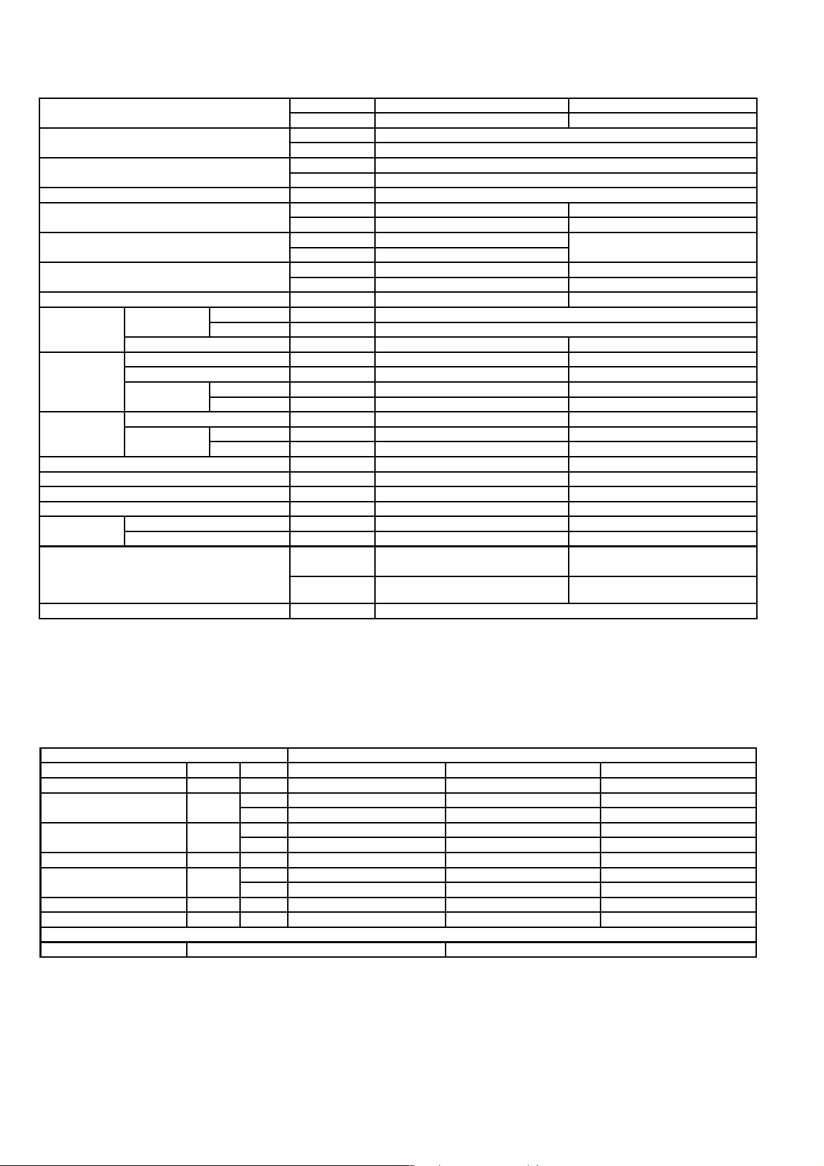
3.3. CS-F28DD3E5 CU-B28DBE8
ITEM / MODEL Indoor Unit Outdoor Unit
Main Body CS-F28DD3E5 CU-B28DBE8
Cooling Capacity kW 7.3
BTU/h 24,900
Heating Capacity kW 8.0
BTU/h 27,300
Refrigerant Charge-less m 30
Standard Air Volume for High Speed m3/min Hi 22 Hi 63
cfm Hi 777 Hi 2226
External Static Pressure Pa Hi 50 -
mmAq Hi 5.1
Outside Dimension (H x W x D) mm 250 x 1000 x 650 795 x 900 x 320
inch 9-26/32 x 39-5/16 x 25-18/32 31-5/16 x 35-7/16 x 12-19/32
Net Weight kg (lbs) 41 (91) 69 (152)
Piping
Connection
Compressor Type, Number of Set - Hermetic, 1
Fan Type, Number of Set Sirocco Fan, 2 Mix flow fan - 1
Air-heat Exchanger (Row x Stage x FPI) Louvre-fin type (3 x 12 x 15) Corrugate-fin type (2 x 36 x 19)
Refrigerant Control - Exp. Valve
Refrigerant Oil (Charged) cm
Refrigerant (Charged) R410A kg (oz) - 2.05 (72)
Running
Adjustment
Noise Level dB (A) Cooling : Hi 43 Lo 39 Cooling 52, Heating 53
Moisture Removal L/h (Pt/h) 4.3 (9.0)
Refrigerant Gas mm (inch) O.D Ø 15.88 (5/8) Flared Type
Liquid mm (inch) O.D Ø 9.53 (3/8) Flared Type
Drain mm Female screw RC1 (PT1) I.D Ø 20 x 1
Starting Method - Permanent Split Capacitor
Motor Type - 2-pole single phase brushless motor
Rated Output kW - 2.2
Motor Type 4-pole single phase induction motor 6-pole single phase induction motor
Rated Output kW 0.085 0.07
3
Control Switch Wired Remote Control Room Temperature Thermostat -
Heating : Hi 43 Lo 39
Power level dB Cooling : Hi 59 Lo 55
Heating : Hi 59 Lo 55
- FV50S (1130)
Cooling 67, Heating 68
1. Cooling capacities are based on indoor temperature of 27°C D.B. (80.6°F D.B.), 19.0°C W.B. (66.2°F W.B.) and outdoor air
temperature of 35°C D.B. (95°F D.B.), 24°C W.B. (75.2°F W.B.)
2. Heating capacities are based on indoor temperature of 20°C D.B. (68°F D.B.) and outdoor air temperature of 7°C D.B. (44.6°F
D.B.), 6°C W.B. (42.8°F W.B.)
ELECTRICAL DATA (50 Hz)
ITEM / MODEL Condition by ISO5151
Volts V 380 400 415
Phase 3N 3N 3N
Power Consumption kW Cool 2.78 2.84 2.89
Heat 2.61 2.69 2.78
Running Current A Cool 4.85 4.9 4.95
Heat 4.65 4.7 4.75
Starting Current A 23 25 27
Power Factor % Cool 87 84 81
Heat 85 83 82
EER W/W 2.63 2.57 2.53
COP W/W 3.07 2.97 2.88
*Power Factor means total figure of compressor, indoor fan motor and outdoor fan motor.
Panasonic Power source AC, 3N~380V, 400V, 415V 50Hz
8
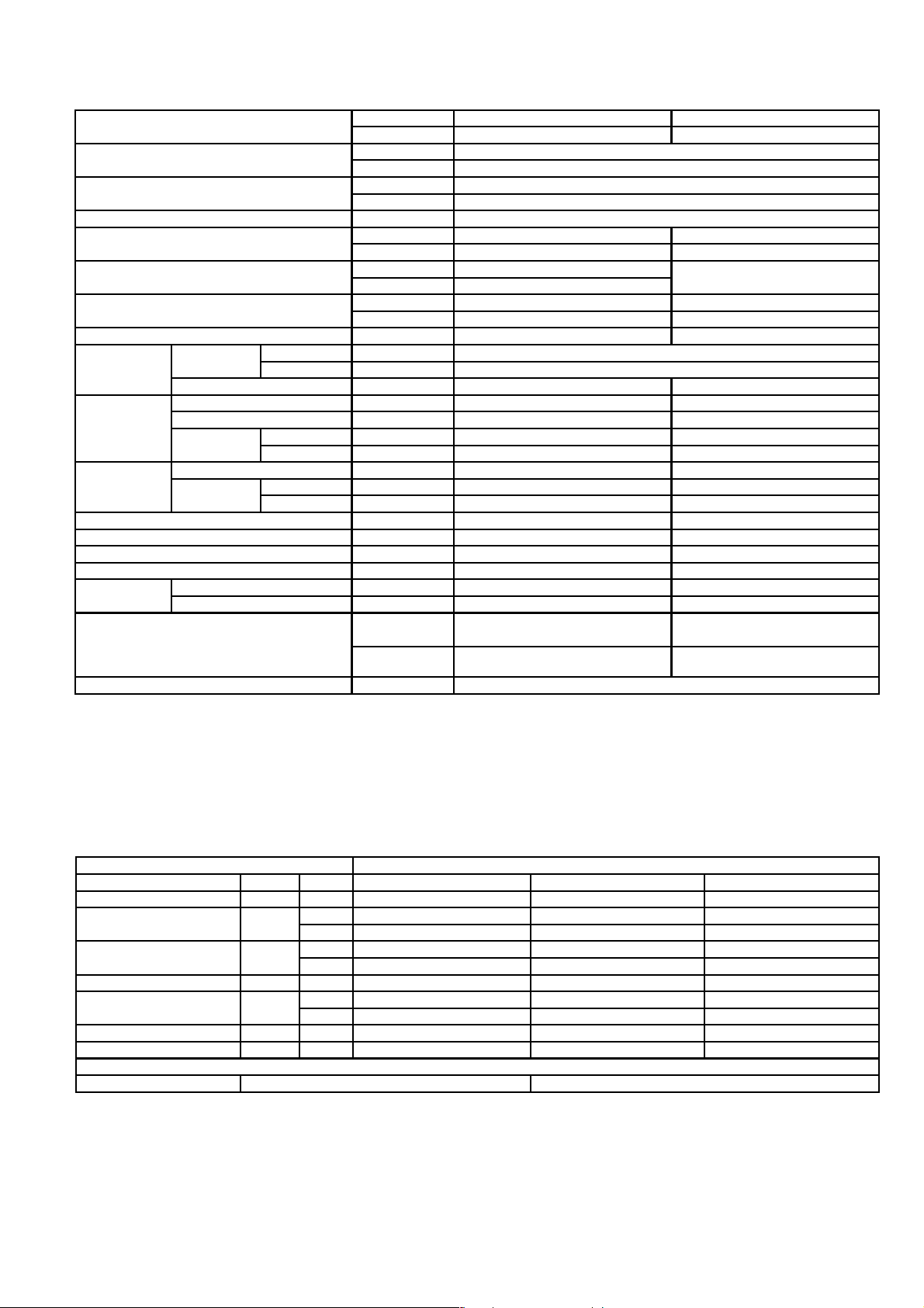
3.4. CS-F34DD3E5 CU-B34DBE5
ITEM / MODEL Indoor Unit Outdoor Unit
Main Body CS-F34DD3E5 CU-B34DBE5
Cooling Capacity kW 10.0
BTU/h 34,100
Heating Capacity kW 11.2
BTU/h 38,200
Refrigerant Charge-less m 30
Standard Air Volume for High Speed m3/min Hi 36 Hi 94
cfm Hi 1271 Hi 3316
External Static Pressure Pa Hi 50 -
mmAq Hi 5.1
Outside Dimension (H x W x D) mm 250 x 1200 x 650 1170 x 900 x 320
inch 9-27/32 x 47-7/32 x 25-19/32 46-1/16 x 35-7/16 x 12-19/32
Net Weight kg (lbs) 47 (104) 102 (225)
Piping
Connection
Compressor Type, Number of Set - Hermetic, 1
Fan Type, Number of Set Sirocco fan, 3 Mix flow fan - 2
Air-heat Exchanger (Row x Stage x FPI) Louvre-fin type (3 x 16 x 15) Corrugate-fin type (2 x 44 x 20)
Refrigerant Control - Exp. Valve
Refrigerant Oil (Charged) cm
Refrigerant (Charged) R410A kg (oz) - 2.7 (95)
Running
Adjustment
Noise Level dB (A) Cooling : Hi 45 Lo 41 Cooling 55, Heating 56
Moisture Removal L/h (Pt/h) 6.0 (12.6)
Refrigerant Gas mm (inch) O.D Ø 15.88 (5/8) Flared Type
Liquid mm (inch) O.D Ø 9.53 (3/8) Flared Type
Drain mm Female screw RC1 (PT1) I.D Ø 20 x 1
Starting Method - Permanent Split Capacitor
Motor Type - 2-pole single phase brushless motor
Rated Output kW - 3.0
Motor Type 4-pole single phase induction motor 6-pole single phase induction motor
Rated Output kW 0.185 0.07 x 2
3
Control Switch Wired Remote Control Room Temperature Thermostat -
Heating : Hi 44 Lo 40
Power level dB Cooling : Hi 60 Lo 56
Heating : Hi 59 Lo 55
- FV68D (1500)
Cooling 69, Heating 70
1. Cooling capacities are based on indoor temperature of 27°C D.B. (80.6°F D.B.), 19.0°C W.B. (66.2°F W.B.) and outdoor air
temperature of 35°C D.B. (95°F D.B.), 24°C W.B. (75.2°F W.B.)
2. Heating capacities are based on indoor temperature 20°C D.B. (68°F D.B.) and outdoor air temperature of 7°C D.B. (44.6°F
D.B.), 6°C W.B. (42.8°F W.B.)
ELECTRICAL DATA (50 Hz)
ITEM / MODEL Condition by ISO5151
Volts V 220 230 240
Phase Single Single Single
Power Consumption kW Cool 3.83 3.88 4.05
Heat 3.86 3.94 4.0
Running Current A Cool 18.4 18.6 18.8
Heat 18.5 18.6 18.9
Starting Current A 92 95 98
Power Factor % Cool 95 91 90
Heat 95 92 88
EER W/W 2.61 2.58 2.47
COP W/W 2.9 2.84 2.8
*Power Factor means total figure of compressor, indoor fan motor and outdoor fan motor.
Panasonic Power source AC, 1~220V, 230V, 240V 50Hz
9
3.5. CS-F34DD3E5 CU-B34DBE8
ITEM / MODEL Indoor Unit Outdoor Unit
Main Body CS-F34DD3E5 CU-B34DBE8
Cooling Capacity kW 10.0
BTU/h 34,100
Heating Capacity kW 11.2
BTU/h 38,200
Refrigerant Charge-less m 30
Standard Air Volume for High Speed m3/min Hi 36 Hi 94
cfm Hi 1271 Hi 3316
External Static Pressure Pa Hi 50 -
mmAq Hi 5.1
Outside Dimension (H x W x D) mm 250 x 1200 x 650 1170 x 900 x 320
inch 9-27/32 x 47-7/32 x 25-19/32 46-1/16 x 35-7/16 x 12-19/32
Net Weight kg (lbs) 47 (104) 100 (221)
Piping
Connection
Compressor Type, Number of Set - Hermetic, 1
Fan Type, Number of Set Sirocco fan, 3 Mix flow fan - 2
Air-heat Exchanger (Row x Stage x FPI) Louvre-fin type (3 x 16 x 15) Corrugate-fin type (2 x 44 x 20)
Refrigerant Control - Exp. Valve
Refrigerant Oil (Charged) cm
Refrigerant (Charged) R410A kg (oz) - 2.7 (95)
Running
Adjustment
Noise Level dB (A) Cooling : Hi 45 Lo 41 Cooling 55, Heating 56
Moisture Removal L/h (Pt/h) 6.0 (12.6)
Refrigerant Gas mm (inch) O.D Ø 15.88 (5/8) Flared Type
Liquid mm (inch) O.D Ø 9.53 (3/8) Flared Type
Drain mm Female screw RC1 (PT1) I.D Ø 20 x 1
Starting Method - Permanent Split Capacitor
Motor Type - 2-pole single phase brushless motor
Rated Output kW - 3.0
Motor Type 4-pole single phase induction motor 6-pole single phase induction motor
Rated Output kW 0.185 0.07 x 2
3
Control Switch Wired Remote Control Room Temperature Thermostat -
Heating : Hi 44 Lo 40
Power level dB Cooling : Hi 60 Lo 56
Heating : Hi 59 Lo 55
- FV68D (1500)
Cooling 69, Heating 70
1. Cooling capacities are based on indoor temperature of 27°C D.B. (80.6°F D.B.), 19.0°C W.B. (66.2°F W.B.) and outdoor air
temperature of 35°C D.B. (95°F D.B.), 24°C W.B. (75.2°F W.B.)
2. Heating capacities are based on indoor temperature 20°C D.B. (68°F D.B.) and outdoor air temperature of 7°C D.B. (44.6°F
D.B.), 6°C W.B. (42.8°F W.B.)
ELECTRICAL DATA (50 Hz)
ITEM / MODEL Condition by ISO5151
Volts V 380 400 415
Phase 3N 3N 3N
Power Consumption kW Cool 3.7 3.75 3.8
Heat 3.54 3.58 3.64
Running Current A Cool 6.35 6.45 6.55
Heat 6.10 6.20 6.30
Starting Current A 41 44 47
Power Factor % Cool 89 84 81
Heat 88 83 80
EER W/W 2.70 2.67 2.63
COP W/W 3.16 3.13 3.08
*Power Factor means total figure of compressor, indoor fan motor and outdoor fan motor.
Panasonic Power source AC, 3N~380V, 400V, 415V 50Hz
10
3.6. CS-F43DD3E5 CU-B43DBE8
ITEM / MODEL Indoor Unit Outdoor Unit
Main Body CS-F43DD3E5 CU-B43DBE8
Cooling Capacity kW 12.5
BTU/h 42,600
Heating Capacity kW 14.0
BTU/h 47,700
Refrigerant Charge-less m 30
Standard Air Volume for High Speed m3/min Hi 40 Hi 94
cfm Hi 1413 Hi 3316
External Static Pressure Pa Hi 50 -
mmAq Hi 5.1
Outside Dimension (H x W x D) mm 250 x 1200 x 650 1170 x 900 x 320
inch 9-27/32 x 47-7/32 x 25-19/32 46-1/16 x 35-7/16 x 12-19/32
Net Weight kg (lbs) 47 (104) 102 (225)
Piping
Connection
Compressor Type, Number of Set - Hermetic, 1
Fan Type, Number of Set Sirocco Fan, 3 Mix flow fan - 2
Air-heat Exchanger (Row x Stage x FPI) Louvre-fin type (3 x 16 x 15) Corrugate-fin type (2 x 44 x 20)
Refrigerant Control - Exp. Valve
Refrigerant Oil (Charged) cm
Refrigerant (Charged) R410A kg (oz) - 3.10 (109)
Running
Adjustment
Noise Level dB (A) Cooling : Hi 45 Lo 41 Cooling 56, Heating 57
Moisture Removal L/h (Pt/h) 7.9 (16.6)
Refrigerant Gas mm (inch) O.D Ø 15.88 (5/8) Flared Type
Liquid mm (inch) O.D Ø 9.53 (3/8) Flared Type
Drain mm Female screw RC1 (PT1) I.D Ø 20 x 1
Starting Method - Permanent Split Capacitor
Motor Type - 2-pole single phase brushless motor
Rated Output kW - 3.75
Motor Type 4-pole single phase induction motor 6-pole single phase induction motor
Rated Output kW 0.185 0.07 x 2
3
Control Switch Wired Remote Control Room Temperature Thermostat -
Heating : Hi 44 Lo 40
Power level dB Cooling : Hi 60 Lo 56
Heating : Hi 59 Lo 55
- FV68D (1500)
Cooling 70, Heating 71
1. Cooling capacities are based on indoor temperature of 27°C D.B. (80.6°F D.B.), 19.0°C W.B. (66.2°F W.B.) and outdoor air
temperature of 35°C D.B. (95°F D.B.), 24°C W.B. (75.2°F W.B.)
2. Heating capacities are based on indoor temperature of 20°C D.B. (68°F D.B.) and outdoor air temperature of 7°C D.B. (44.6°F
D.B.), 6°C W.B. (42.8°F W.B.)
ELECTRICAL DATA (50 Hz)
ITEM / MODEL Condition by ISO5151
Volts V 380 400 415
Phase 3N 3N 3N
Power Consumption kW Cool 4.75 4.8 4.87
Heat 4.61 4.68 4.78
Running Current A Cool 8.0 8.1 8.2
Heat 7.8 7.9 8.0
Starting Current A 54 57 60
Power Factor % Cool 90 86 83
Heat 90 86 83
EER W/W 2.63 2.60 2.57
COP W/W 3.04 2.99 2.93
*Power Factor means total figure of compressor, indoor fan motor and outdoor fan motor.
Panasonic Power source AC, 3N~380V, 400V, 415V 50Hz
11

3.7. CS-F50DD3E5 CU-B50DBE8
ITEM / MODEL Indoor Unit Outdoor Unit
Main Body CS-F50DD3E5 CU-B50DBE8
Cooling Capacity kW 13.5
BTU/h 46,000
Heating Capacity kW 15.0
BTU/h 51,100
Refrigerant Charge-less m 30
Standard Air Volume for High Speed m3/min Hi 44 Hi 96
cfm Hi 1555 Hi 3387
External Static Pressure Pa Hi 50 -
mmAq Hi 5.1
Outside Dimension (H x W x D) mm 250 x 1200 x 650 1170 x 900 x 320
inch 9-27/32 x 47-7/32 x 25-19/32 46-1/16 x 35-7/16 x 12-19/32
Net Weight kg (lbs) 47 (104) 102 (225)
Piping
Connection
Compressor Type, Number of Set - Hermetic, 1
Fan Type, Number of Set Sirocco Fan, 3 Mix flow fan - 2
Air-heat Exchanger (Row x Stage x FPI) Louvre-fin type (3 x 16 x 15) Corrugate-fin type (2 x 44 x 20)
Refrigerant Control - Exp. Valve
Refrigerant Oil (Charged) cm
Refrigerant (Charged) R410A kg (oz) - 3.4 (120)
Running
Adjustment
Noise Level dB (A) Cooling : Hi 46 Lo 42 Cooling 56, Heating 57
Moisture Removal L/h (Pt/h) 8.6 (18.1)
Refrigerant Gas mm (inch) O.D Ø 15.88 (5/8) Flared Type
Liquid mm (inch) O.D Ø 9.53 (3/8) Flared Type
Drain mm Female screw RC1 (PT1) I.D Ø 20 x 1
Starting Method - Permanent Split Capacitor
Motor Type - 2-pole single phase brushless motor
Rated Output kW - 4.5
Motor Type 4-pole single phase induction motor 6-pole single phase induction motor
Rated Output kW 0.185 0.07 x 2
3
Control Switch Wired Remote Control Room Temperature Thermostat -
Heating : Hi 45 Lo 41
Power level dB Cooling : Hi 61 Lo 57
Heating : Hi 60 Lo 56
- FV68D (1500)
Cooling 70, Heating 71
1. Cooling capacities are based on indoor temperature of 27°C D.B. (80.6°F D.B.), 19.0°C W.B. (66.2°F W.B.) and outdoor air
temperature of 35°C D.B. (95°F D.B.), 24°C W.B. (75.2°F W.B.)
2. Heating capacities are based on indoor temperature of 20°C D.B. (68°F D.B.) and outdoor air temperature of 7°C D.B. (44.6°F
D.B.), 6°C W.B. (42.8°F W.B.)
ELECTRICAL DATA (50 Hz)
ITEM / MODEL Condition by ISO5151
Volts V 380 400 415
Phase 3N 3N 3N
Power Consumption kW Cool 5.26 5.31 5.46
Heat 5.03 5.08 5.13
Running Current A Cool 8.7 8.8 9.1
Heat 8.2 8.4 8.7
Starting Current A 55 58 61
Power Factor % Cool 92 87 83
Heat 93 87 82
EER W/W 2.57 2.54 2.47
COP W/W 2.98 2.95 2.92
*Power Factor means total figure of compressor, indoor fan motor and outdoor fan motor.
Panasonic Power source AC, 3N~380V, 400V, 415V 50Hz
12
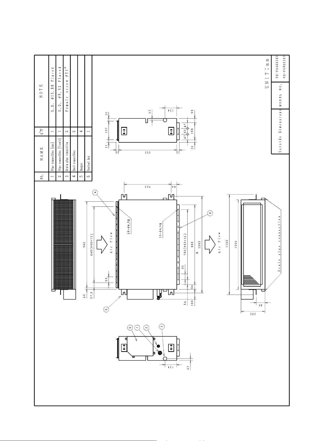
4 DIMENSIONS
4.1. CS-F24DD3E5 CS-F28DD3E5
13

4.2. CS-F34DD3E5 CS-F43DD3E5 CS-F50DD3E5
14
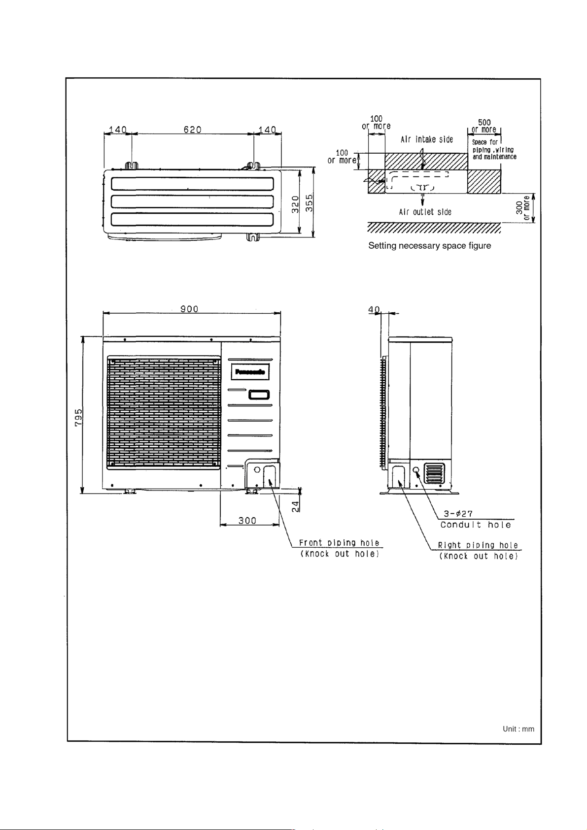
4.3. CU-B24DBE5 CU-B28DBE5 CU-B28DBE8
15
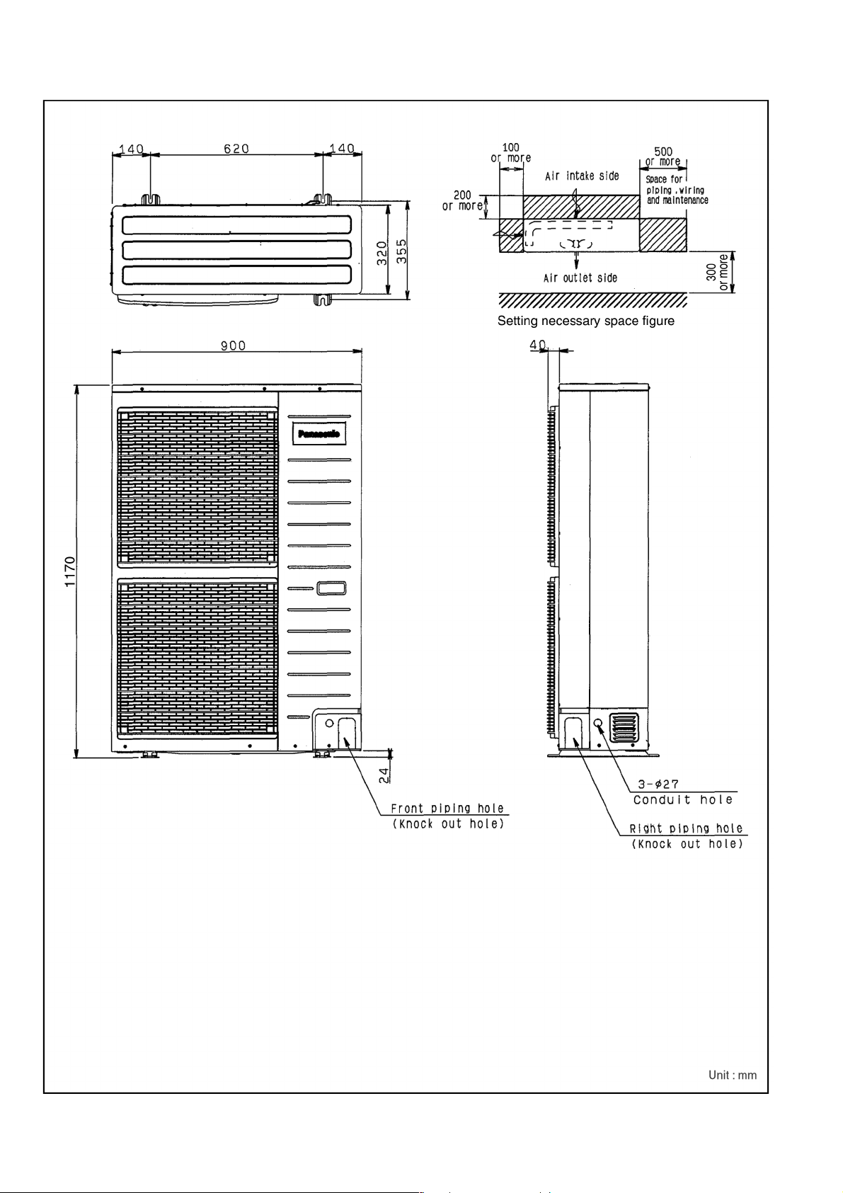
4.4. CU-B34DBE5 CU-B34DBE8 CU-B43DBE8 CU-B50DBE8
16
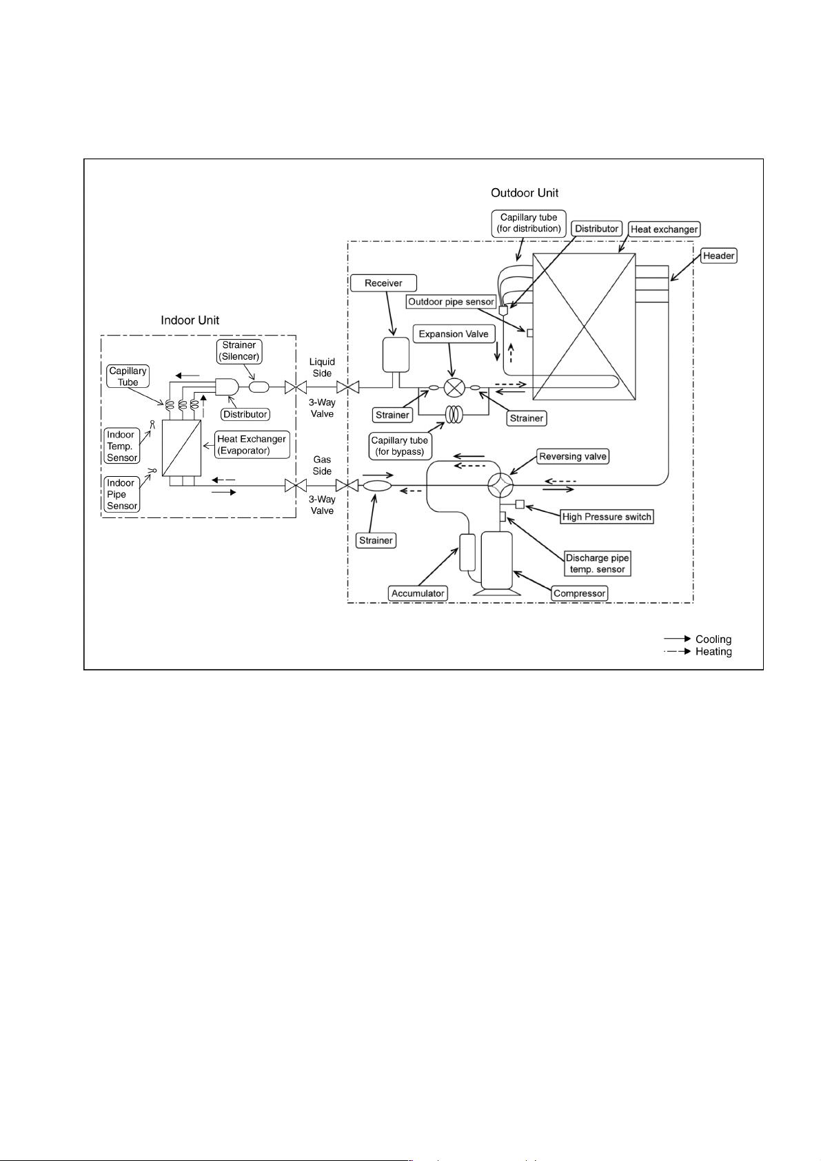
5 REFRIGERATION CYCLE
5.1. CS-F24DD3E5 CU-B24DBE5
CS-F28DD3E5 CU-B28DBE5 CU-B28DBE8
17
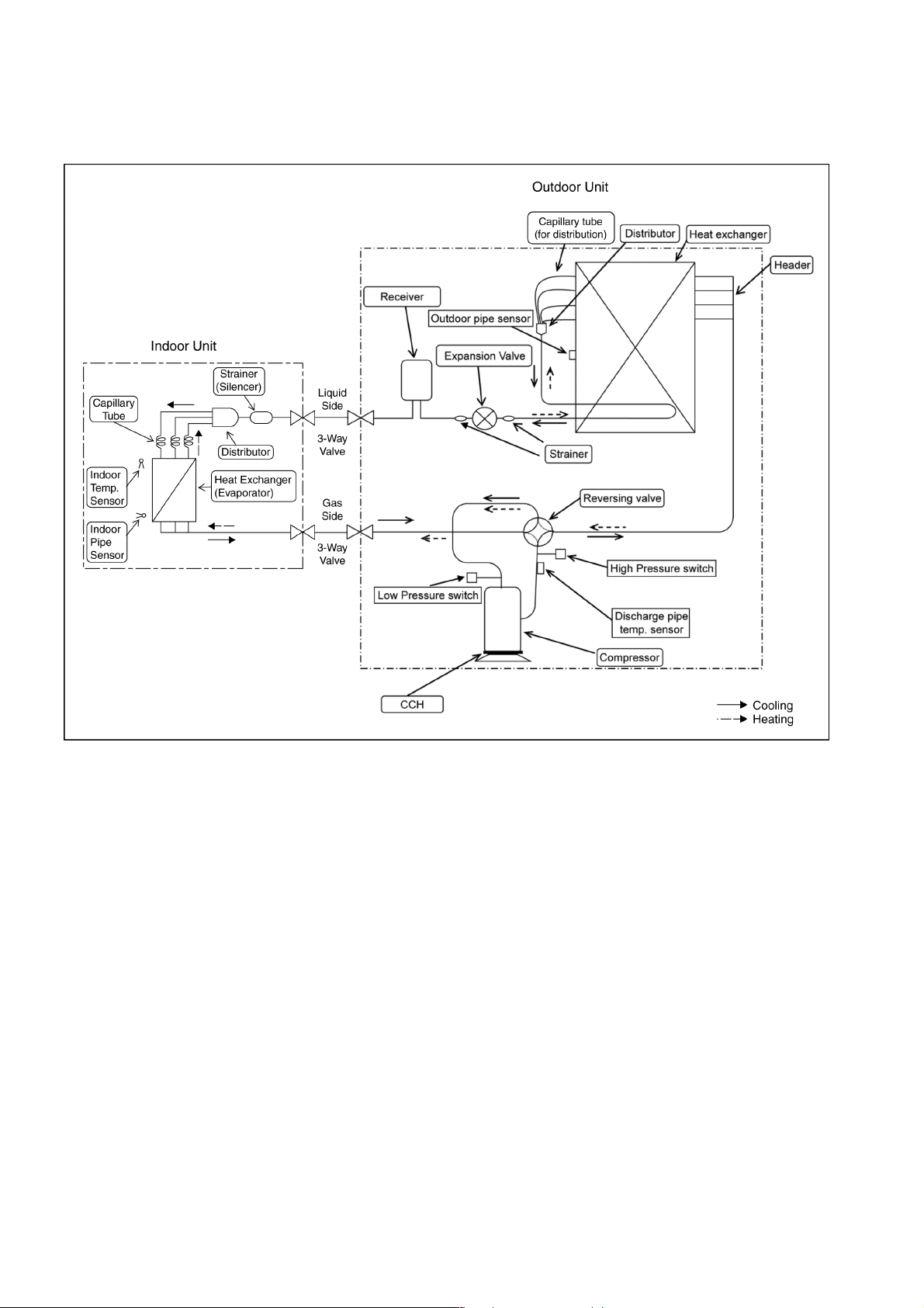
5.2. CS-F34DD3E5 CU-B34DBE5 CU-B34DBE8
CS-F43DD3E5 CU-B43DBE8
CS-F50DD3E5 CU-B50DBE8
18
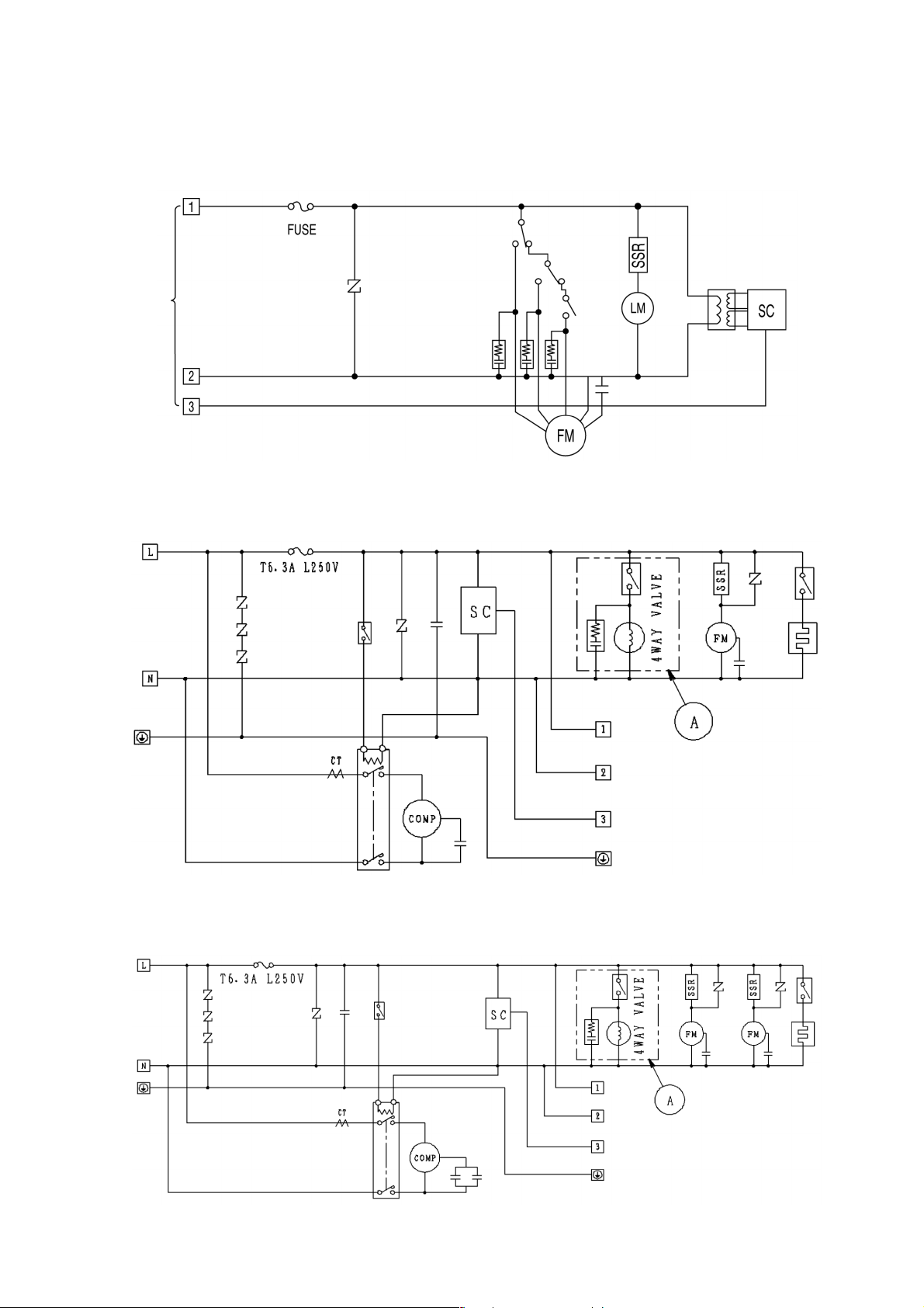
6 BLOCK DIAGRAM
6.1. CS-F24DD3E5 CS-F28DD3E5 CS-F34DD3E5 CS-F43DD3E5
CS-F50DD3E5
6.2. CU-B24DBE5 CU-B28DBE5
6.3. CU-B34DBE5
19

6.4. CU-B28DBE8
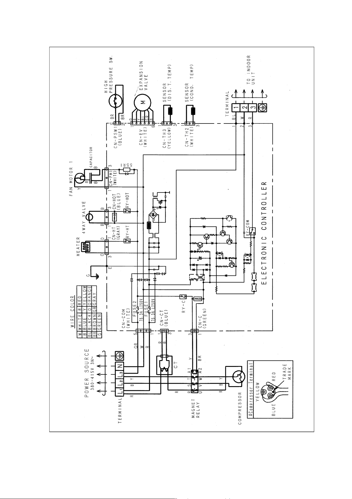
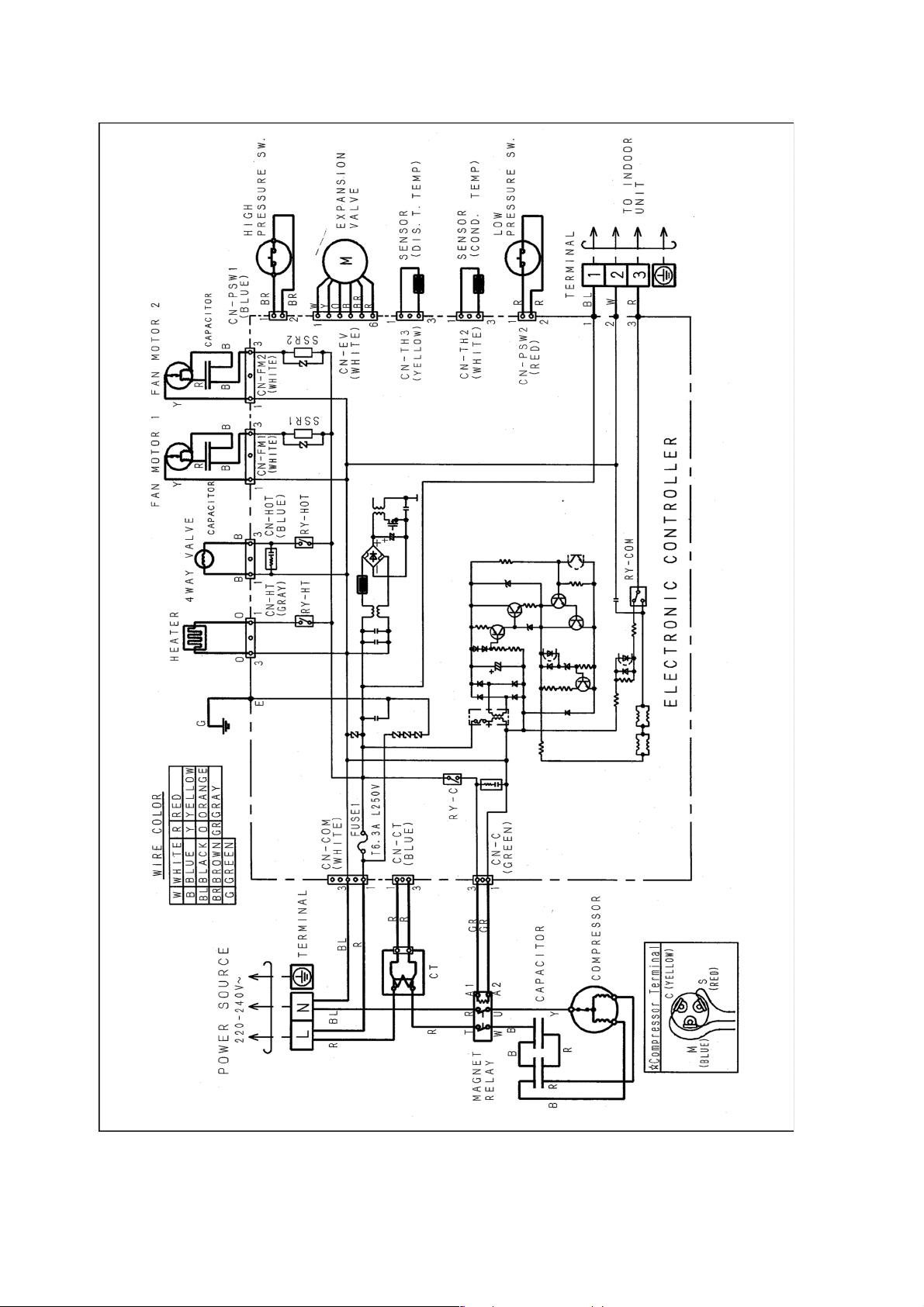
6.5. CU-B34DBE8 CU-B43DBE8 CU-B50DBE8
20

7 WIRING DIAGRAM
7.1. CS-F24DD3E5 CS-F28DD3E5 CS-F34DD3E5 CS-F43DD3E5
CS-F50DD3E5
21

7.2. CU-B24DBE5 CU-B28DBE5
22
7.3. CU-B28DBE8
23
7.4. CU-B34DBE5
24

7.5. CU-B34DBE8 CU-B43DBE8 CU-B50DBE8
25
8 WIRED REMOTE CONTROL OPERATING INSTRUCTIONS
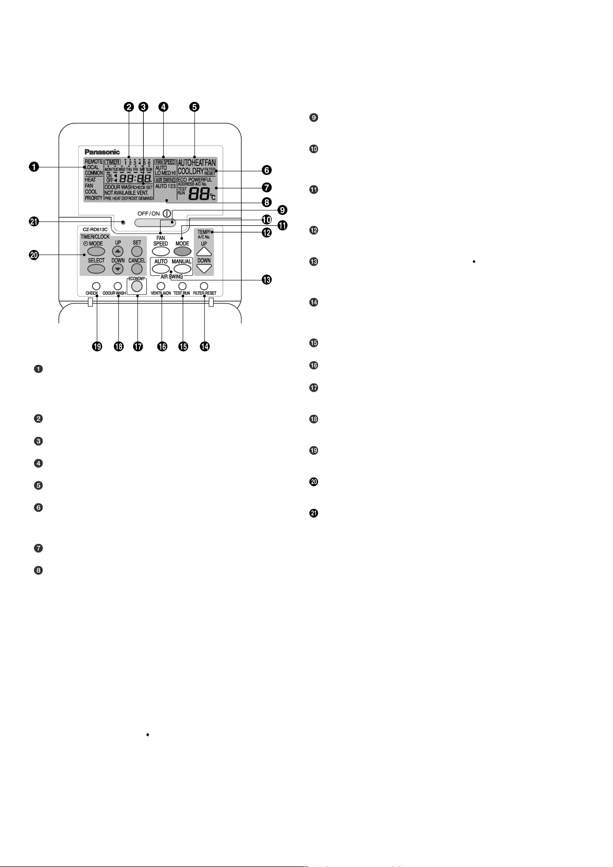
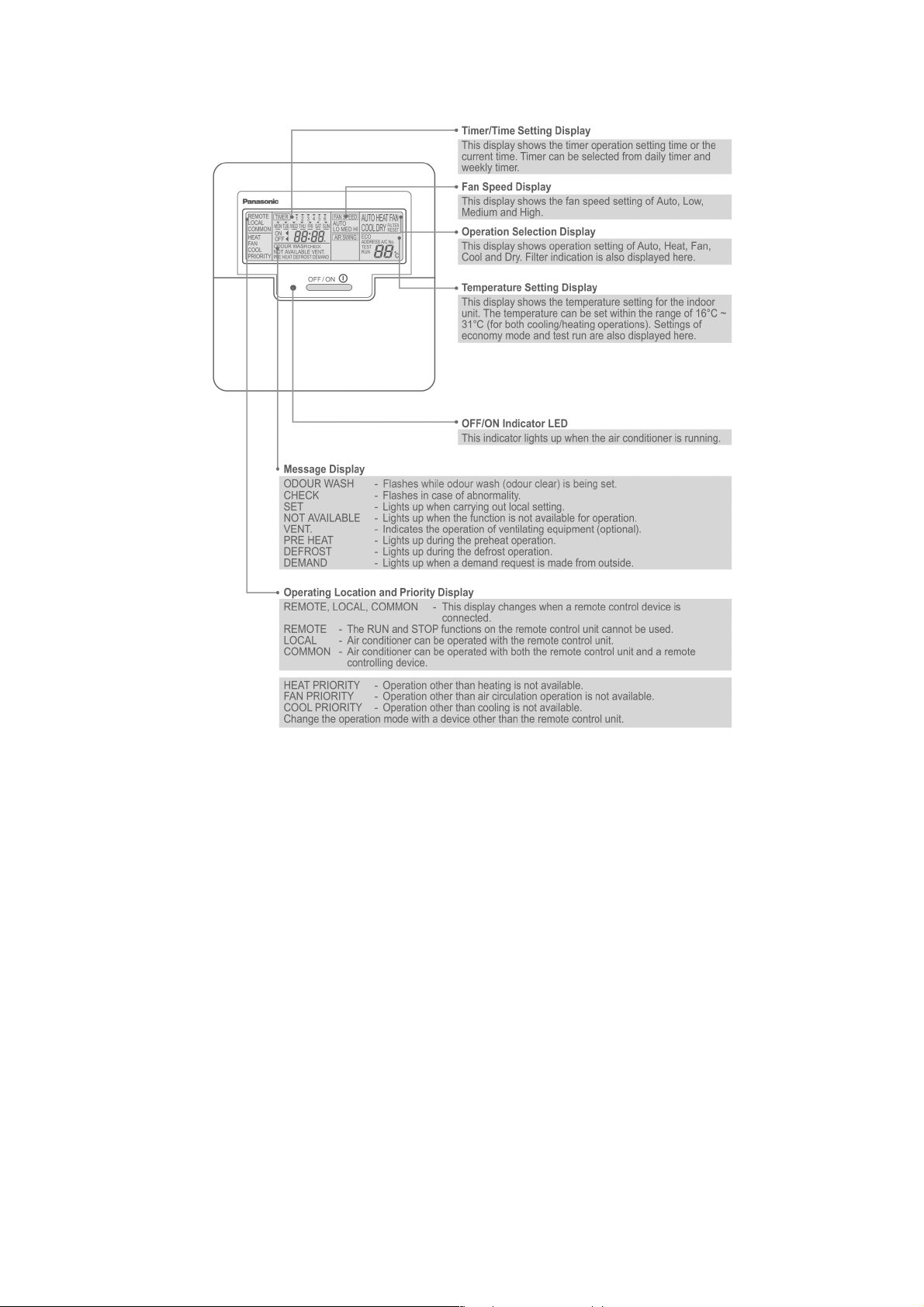
8.1. Name and function of each part
OFF/ON button
Used to start and stop the operation.
FAN SPEED button
Used to select the fan speed of high (HI), medium (MED), low
(LO) or auto (AUTO).
MODE button
Used to select the operation of AUTO, HEAT, FAN, COOL, or
DRY.
TEMP (UP/DOWN) buttons
Used to select the desired temperature.
AIR SWING (AUTO/MANUAL) buttons
Used to determined the air swing condition, either auto or
manual.
FILTER RESET button
Press to reset the “FILTER RESET” display after washing the
filter.
TEST RUN button*
REMOTE
The OFF/ON button cannot be used.
LOCAL
All wired remote control buttons can be used.
Time/time setting display
Check display
Fan speed display
Operation mode selection display
FILTER RESET display
(Appears after the cumulative running time reaches
approximately 2,500 hours of operation.)
Temperature setting display (16°C - 31°C)
Airflow direction setting display
VENTILATION button*
ECONOMY operation button
Provides Energy saving function
ODOUR WASH button
Provides deodorizing function.
CHECK button
Press this button if the check display is flashing.
TIMER/CLOCK SET buttons
Used to set the timer operation and the current time.
Operation indicator
Lights up when the unit in operation.
NOTES
Ensure that the correct button is pressed as simultaneous pressing of the multiple buttons will not make the setting correct.
•
The illustration above is for explanatory purposes only. The appearance will be different during actual operation.
•
Do not operate the remote control with wet hands. Otherwise, electric shock or malfunction may occur.
•
Do not press the remote control buttons with sharp object as this may damage the remote control.
•
Buttons marked with * are not needed for normal operation. If one of these buttons is pressed by mistake, press the same
•
button once more to cancel the operation.
When the power resumed after power failure, the unit will restart automatically with all the previous settings preserved by
•
the memory function. (Auto restart function)
Buttons marked with
•
are not available for operation. If one of these buttons is pressed function will not be available.
26
8.2. Remote control - display
27
8.3. Remote control - panel
28
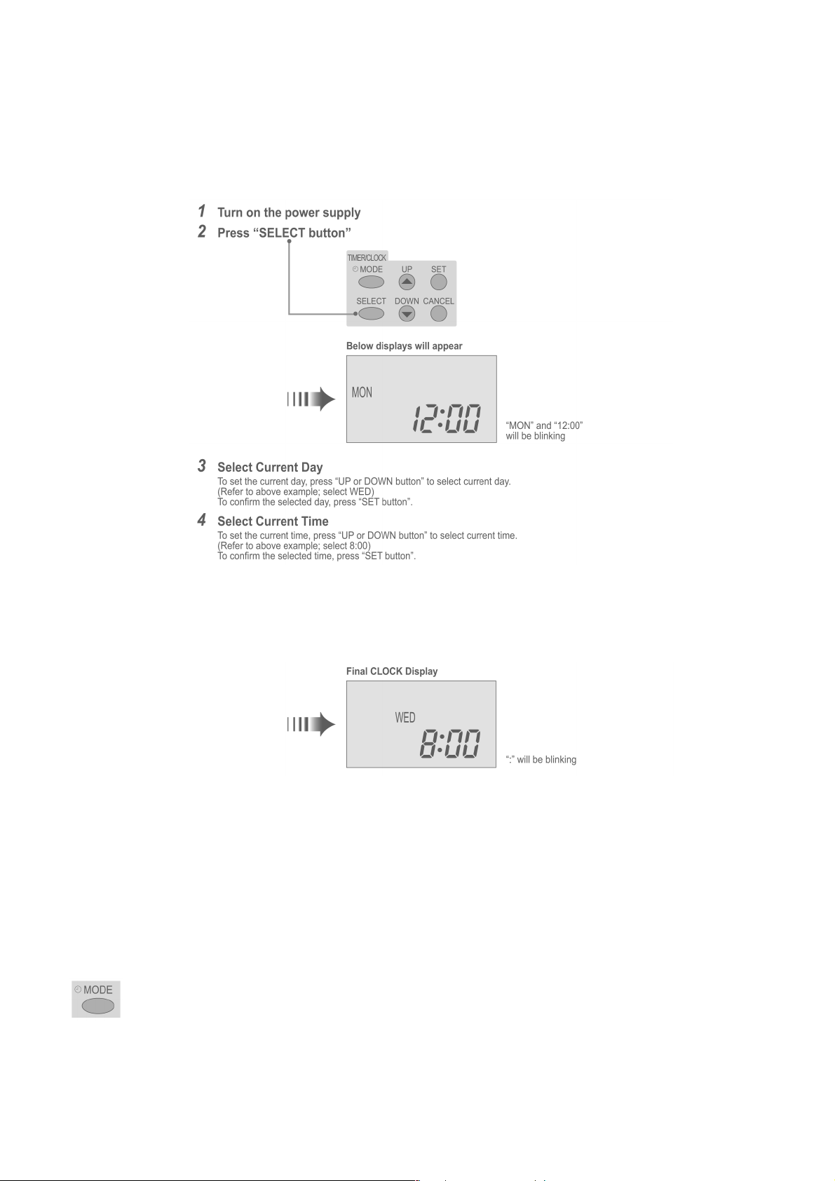
8.4. How to set remote control day and time
• The day and time need to be set when you turn on the power for the first time or after a long time has elapsed since the power
was last turned on.
• The day and time become the standard time for all the Timer operations.
• Set the day and time accurately.
• Example : Current Day is Wednesday and Current Time is 8:00.
Note:
• Press “UP button” to increase or “DOWN button” to decrease (interval 1 minute) or hold the button to change the time faster.
• If the “UP or DOWN button” is not pressed for 30 seconds during the day or time setting or if the “SELECT button” is
pressed, the setting at that moment is confirmed and setting will end.
8.5. How to select the timer
• 2 types of Timer mode can be selected on the remote control.
− Daily Timer
− Weekly Timer
• These timers cannot be operated simultaneously.
• Select one of these Timers for your convenience.
How to Change the Display
• Press once to change the display from CLOCK to Timer or vice-versa.
• Press more than 3 seconds to change the display from Daily Timer to Weekly Timer or vice-versa.
29

CLOCK Display (To set current Day and Time)
Note:
• The above display is shown if no valid timer setting is made.
• If valid timer setting is made.
− Timer
and setting will be displayed.
− If you want to check the current time and day, press “MODE button” once.
(However, after a few seconds, the display will change back to Timer
8.6. Daily timer setting
and the setting)
• Display
• How to Set Daily Timer
− You can set only “ON” or only “OFF” or “ON” and “OFF” in a day.
1. Change Display
Press “MODE button” to change the display to daily timer.
2. ON-Timer, OFF-Timer and select Time
Press “SELECT button”; ON-Timer setting will be displayed.
Press “UP or DOWN button” to select the desired time, (Example: ON 9:00), then press “SET button” to confirm
the selected desired time.
Or press “CANCEL button” if you do not want any setting for ON-Timer.
Then OFF-Timer setting will be displayed.
Press “UP or DOWN button” to select the desired time, (Example: OFF 18:30), then press “SET button” to
confirm the selected desired time.
Or press “CANCEL button” if you do not want any setting for OFF-Timer.
Note:
• The setting timer will be activated everyday.
• Timer nearer to the current time will be activated first.
30
 Loading...