

Page 1

TECHNICAL & SERVICE MANUAL
OUTDOOR UNIT : CU-3KS19NBU
CU-4KS24NBU
CU-4KS31NBU
DC INVERTER MULTI-SYSTEM AIR CONDITIONER
CU-3KS19NBU
CU-4KS24NBU
Capacity at 230V
19,700 BTU/h
25,400 BTU/h
30,600 BTU/h
Outdoor Model No.
CU-3KS19NBU
CU-4KS24NBU
CU-4KS31NBU
Product Code No.
1 852 361 24
1 852 361 25
1 852 361 26
< Applicable Indoor Units >
Wall mounted type
CS-MKS7NKU
CS-MKS9NKU
CS-MKS12NKU
CS-MKS18NKU
CS-MKS24NKU
Semi-concealed type
CS-MKS9NB4U & CZ-18BT1U
CS-MKS12NB4U & CZ-18BT1U
CS-KS18NB4UW & CZ-18BT1U
CU-4KS31NBU
IMPORTANT
These air conditioners employ new
refrigerant R410A.
Pay special attention when
servicing the unit.
REFERENCE NO.
SM700877
Page 2

SAFETY PRECAUTIONS
• Before doing repair work, please read the " SAFETY PRECAUTIONS" carefully and fully understand them.
• The precautionary items here are divided into " Warning" and " Caution" items.
Items in particular which may cause death or serious injury to the service personnel if the work is not performed correctly,
are included in the " Warning" table.
However, even precautionary items identified as " Caution" also have the potential for serious consequences
if not performed correctly.
Important safety precautions are described for all items in both categories. Be sure to carefully follow all of them.
• Symbol Indication
: This symbol indicates items to which we need to pay attention.
In this triangle, a definite precautionary item is described.
: This symbol indicates the item to be prohibited.
In or close to this circle, a prohibited item is described.
: This symbol indicates the items requiring special attention or instruction.
In or close to this circle, a prohibited item is described.
• After doing repair work, perform a test run to confirm that there are no abnormalities.
At the same time, explain the precautions in use to the user.
Warning
Before performing an overhaul, disconnect the power plug or power cable from the unit.
Performing the work with the power supplied to the unit, may cause an electric shock.
When repair work or circuit inspection that requires power supply for the air conditioner, is to be performed,
do not touch the charging section.
Doing so may cause an electric shock.
Prohibit
For the step-up capacitor attached to the electric section, perform the repair work after sufficiently discharging it.
Insufficient capacitor discharge may cause an electric shock.
Do not perform repair work on the electric sections with wet hands.
Doing so may cause an electric shock.
Do not start or stop the air conditioner by means of connecting or disconnecting the power plug.
Doing so may cause an electric shock or fire.
When conducting repair work only use components included in the parts list for the corresponding unit and perform
the work with the appropriate tools.
Incorrect or poor repair work may cause an electric shock or fire.
Never modify the unit.
Doing so may cause an electric shock or fire.
Perform all electric work according to local applicable regulations related to electrical equipment or interior wiring
regulation and make sure to use the exclusive circuit.
Insufficient capacity to the electric circuit or defective arrangement results may cause an electric shock or fire.
Make sure to replace any power cable or lead wire showing any signs of scratch or deterioration.
Failure to do so may cause an electric shock, overheating or fire.
Make sure that there is no dust on or slack in the power plug and insert fully into the socket.
Dust or incomplete connections may cause an electric shock or fire.
Do not damage or process the power cord, as it may cause an electric shock or fire.
Prohibit
Prohibit
Prohibit
Prohibit
For the wiring between the indoor unit and outdoor unit, securely fix the specified cable onto the terminal plate.
Poorly fixed wiring may cause a heat or fire.
After connecting the wiring between the indoor unit and outdoor unit, attach the terminal cover securely.
Incomplete attachment of the terminal cover may cause overheating or fire.
2
Page 3

Warning
If refrigerant gas blows off during the work, do not touch the refrigerant gas as it may cause frostbite.
If refrigerant gas leaks during the work, ventilate the room.
If refrigerant gas catches fire, harmful gas may be generated.
Do not mix any gas other than the specified refrigerant gas in the refrigerating cycle.
If air or other contaminants mix with the gas, pressure will become extremely high in the refrigerating cycle,
which may cause a unit breakdown."
When the welded section of the compressor intake or discharge pipe is to be disconnected, perform it in
a well-ventilated place after sufficiently recovering the refrigerant gas.
Any residue gas may jet out refrigerant or refrigerating machine oil, which may cause an injury.
When the work is to be performed in a high place (About 2 meters or more), make sure to wear a safety helmet,
gloves and safety belt. Insufficient safety gear may cause a serious injury in case of a fall.
When the unit is to be relocated, confirm that the new installation location has sufficient strength for the weight of the unit.
Insufficient strength of the installation location and incomplete installation work may cause an injury due to
the unit falling.
When the remote controller batteries are replaced, dispose of the old batteries out of the reach of children.
If a child swallows a battery, make sure that the child gets immediate medical attention.
Caution
Prohibit
Prohibit
Do not wash the air conditioner with water, as this may cause an electric shock or fire.
For the repair work in places with high humidity or moisture, make sure to ground the unit.
Failure to do so may cause an electric shock.
Confirm that the component attachment position, wiring condition, soldering condition and connector connection
are normal.
If not, it may cause overheating or fire.
Confirm that the temperature around the compressor is not too high, and then perform the repair work.
Failure to do so may cause a burn.
Perform welding work in a place with good ventilation.
If the work is performed in a poorly ventilated area, it might cause a lack of oxygen.
If the installation plate or attachment frame has deteriorated due to corrosion, etc., replace it.
Failure to do so may cause an injury due to the unit falling.
When the cleaning is to be performed, make sure to turn off the power and pull out the plug.
Touching the fan that is rotating at high speed may result in an injury.
When the indoor unit is to be removed, do not place it on an incline.
Doing so may cause wet furniture because water left inside may trickle down.
Do not hold the sharp end of the unit or the aluminum fins, as it may cause an injury to your hand or finger.
Prohibit
Prohibit
Prohibit
After repairs, make sure to measure the insulation resistance and confirm that the value is 1 Mohm or more.
Any insulation error may cause an electric shock.
After repairs, make sure to check the drainage of the indoor unit.
Inappropriate drainage may cause wet furniture and floors due to water leakage.
3
Page 4

SAFETY PRECAUTIONS
Table of Contents
Page
..............................................................................................................
2
TABLE OF CONTENTS
APPLICABLE INDOOR UNITS
1. OPERATING RANGE
2. SPECIFICATIONS
2-1. Unit Specifications
2-2. Major Component Specifications
2-3. Other Component Specifications
3. DIMENSIONAL DATA
4. REFRIGERANT FLOW DIAGRAM
4-1. Refrigerant Flow Diagram
5. PERFORMANCE DATA
5-1. Temperature Charts
5-2. Cooling Capacity
5-3. Cooling Capacity (Low Ambient)
......................................................................................................................
.....................................................................................................
...................................................................................................................
.............................................................................................................
...................................................................................................................
............................................................................................................
................................................................................................................
.......................................................................................
.......................................................................................
...................................................................................................
........................................................................................
4
6
7
8
17
20
21
24
27
50
56
6. ELECTRICAL DATA
6-1. Electric Wiring Diagrams
7. FUNCTIONS
7-1. Explanation of Functions
7-2. Protective Functions
8. TROUBLESHOOTING (BEFORE CALLING FOR SERVICE)
8-1. Precautions before Performing Inspection or Repair
8-2. Trouble Diagnosis by Error Monitop Lamps
8-3. Checking the Outdoor System
8-4. Trouble Diagnosis of Each Part
8-5. Trouble Diagnosis of Fan Motor
....................................................................................................
.....................................................................................................
...........................................................................................................
.......................................................................
...........................................................................................
.........................................................................................
.........................................................................................
..........................................................
62
65
69
71
72
73
74
78
4
Page 5

9. REFRIGERANT R410A:
SPECIAL PRECAUTIONS WHEN SERVICING UNIT
9-1. Characteristics of New Refrigerant R410A
9-2. Checklist before Servicing
9-3. Tools Specifically for R410A
9-4. Tubing Installation Procedures
9-5. In Case of Compressor Malfunction
9-6. In Case Refrigerant is Leaking
9-7. Charging Additional Refrigerant
9-8. Retro-Fitting Existing Systems
...................................................................................................
................................................................................................
............................................................................................
....................................................................................
............................................................................................
..........................................................................................
............................................................................................
Page
.........................................................................
79
80
81
81
82
84
85
85
APPENDIX A INSTALLATION INSTRUCTIONS
.............................................................................
A-1
5
Page 6

APPLICABLE INDOOR UNITS
Wall Mounted Type
Indoor Unit
CS-MKS7NKU
Multi-Outdoor Unit
CS-MKS9NKU CS-MKS12NKU CS-MKS18NKU CS-MKS24NKU
3-Room
4-Room
4-Room
CU-3KS19NBU
CU-4KS24NBU
CU-4KS31NBU
Semi-Concealed Type
Indoor Unit
Multi-Outdoor Unit
3-Room
4-Room
4-Room
CU-3KS19NBU
CU-4KS24NBU
CU-4KS31NBU
YES
YES
YES
CS-MKS9NB4U
&
CZ-18BT1U
YES
YES
YES
YES
YES
YES
CS-MKS12NB4U
&
CZ-18BT1U
YES
YES
YES
YES
YES
YES
CS-KS18NB4UW
&
CZ-18BT1U
YES
YES
YES
YES
YES
YES
NO
YES
YES
6
Page 7

1. OPERATING RANGE
Temperature Indoor Air Intake Temp. Outdoor Air Intake Temp.
Cooling
Maximum
Minimum
95 °F DB / 71 °F WB
67 °F DB / 57 °F WB
115 °F DB
14 °F DB
7
Page 8

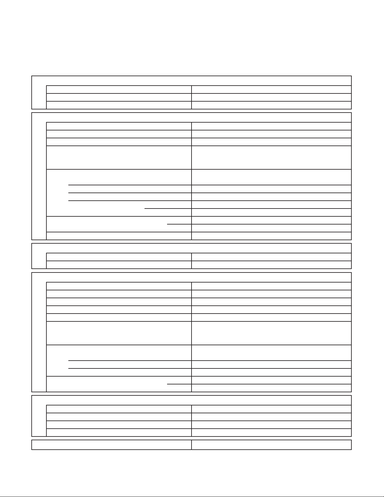
2. SPECIFICATIONS
2-1. Unit Specifications
Outdoor Unit CU-3KS19NBU
Indoor Unit CS-MKS9NKU × 2
Duct Less Type Rated
Type
Total Capacity
Sensible Capacity
Latent Capacity
Performance
Available Voltage Range
Running Amperes
EER BTU/h/W 12.0
SEER BTU/Wh 18.0
Compressor Locked Rotor Amperes
Electrical Rating
Fuse or Circuit Breaker Capacity A 15
Control Microprocessor
Fan Speeds Auto (Hi, Me, Lo)
Compressor
Refrigerant / Amount charged at shipment Ibs (g)
Refrigerant Control
Operation Sound (High) Cool
Features
Refrigerant Tubing Connections
Max. allowable tubing length per unit
Refrigerant inch (mm)
Tube Diameter inch (mm)
Unit Dimensions
Height × Width × Depth
Package Dimensions
Height × Width × Depth
Weight
Dimensions & Weight
Shipping Volume
Remarks:
1. The values shown in performance section and electrical rating section above are based on the following unit combination.
For other combination unit, please refer to the "Unit Combination Tables" in this manual.
Indoor Unit : CS-MKS9NKU 2units Outdoor Unit : CU-3KS19NBU 1unit
The combination indoor unit is AHRI 210/240.
2. Rating conditions are: Cooling : Indoor air temp. 80 °F DB / 67 °F WB
Outdoor air temp. 95 °F DB / 75 °F WB
Narrow tube
Wide tube
Net
Shipping
BTU/h
kW
BTU/h
BTU/h
V
A
WPower Input
%Power Factor 98
A 13.0
dB-A
ft (m)
inch
(mm)
inch
(mm)
Ibs (kg)
Ibs (kg)
cu.ft (m3)
3-Room Multi Outdoor Unit
3Number of Connectable Indoor Units
3Number of Operatable Indoor Units
230V Single-Phase 60HzVoltage Rating
Cooling
17,000
29-1/8 × 35-7/16 × 12-19/32
34-3/16 × 41-11/32 × 16-21/32
DATA SUBJECT TO CHANGE WITHOUT NOTICE.
( 6,800 to 18,800 )
5.00
( 1.90 to 5.50 )
14,300
2,700
1,707 (2,900)Air Circulation (High) ft3/min (m3/h)
187 to 253
6.3
1,420
Outdoor Unit
DC Twin Rotary (Inverter)
R410A / 6.17 (2,800)
Electric Expansion Valve
50
Flare Type
82 (25)
1/4 (6.35) × 3
3/8 (9.52) × 3
Outdoor Unit
(740 × 900 × 320)
(868 × 1,050 × 423)
138.9
(63.0)
147.7
(67.0)
13.41 (0.38)
< 230V >
8
Page 9

Outdoor Unit CU-3KS19NBU
Indoor Unit CS-MKS9NKU ×
Type
Total Capacity
Sensible Capacity
Latent Capacity
Performance
Available Voltage Range
Running Amperes
EER BTU/h/W 12.5
Compressor Locked Rotor Amperes
Electrical Rating
Fuse or Circuit Breaker Capacity A 15
Control Microprocessor
Fan Speeds Auto (Hi, Me, Lo)
Compressor
Refrigerant / Amount charged at shipment Ibs (g)
Refrigerant Control
Operation Sound (High) Cool
Features
Refrigerant Tubing Connections
Max. allowable tubing length per unit
Refrigerant inch (mm)
Tube Diameter inch (mm)
Unit Dimensions
Height × Width × Depth
Package Dimensions
Height × Width × Depth
Weight
Dimensions & Weight
Shipping Volume
3
Narrow tube
Wide tube
Net
Shipping
BTU/h
kW
BTU/h
BTU/h
V
A
WPower Input
%Power Factor 98
A 13.0
dB-A
ft (m)
inch
(mm)
inch
(mm)
Ibs (kg)
Ibs (kg)
cu.ft (m3)
34-3/16 × 41-11/32 × 16-21/32
DATA SUBJECT TO CHANGE WITHOUT NOTICE.
3-Room Multi Outdoor Unit
230V Single-Phase 60HzVoltage Rating
Cooling
18,800
29-1/8 × 35-7/16 × 12-19/32
( 9,800 to 18,800 )
5.50
( 2.90 to 5.50 )
16,000
1,707 (2,900)Air Circulation (High) ft3/min (m3/h)
187 to 253
1,500
Outdoor Unit
DC Twin Rotary (Inverter)
R410A / 6.17 (2,800)
Electric Expansion Valve
Flare Type
82 (25)
1/4 (6.35) × 3
3/8 (9.52) × 3
Outdoor Unit
(740 × 900 × 320)
(868 × 1,050 × 423)
138.9
147.7
13.41 (0.38)
< 230V >
3Number of Connectable Indoor Units
3Number of Operatable Indoor Units
2,800
6.7
50
(63.0)
(67.0)
Remarks:
1. The values shown in performance section and electrical rating section above are based on the following unit combination.
For other combination unit, please refer to the "Unit Combination Tables" in this manual.
Indoor Unit : CS-MKS9NKU 3units Outdoor Unit : CU-3KS19NBU 1unit
2. Rating conditions are: Cooling : Indoor air temp. 80 °F DB / 67 °F WB
Outdoor air temp. 95 °F DB / 75 °F WB
9
Page 10

Outdoor Unit CU-3KS19NBU
Indoor Unit CS-MKS9NKU ×
Type
Total Capacity
Sensible Capacity
Latent Capacity
Performance
Available Voltage Range
Running Amperes
EER BTU/h/W 12.5
Compressor Locked Rotor Amperes
Electrical Rating
Fuse or Circuit Breaker Capacity A 15
Control Microprocessor
Fan Speeds Auto (Hi, Me, Lo)
Compressor
Refrigerant / Amount charged at shipment Ibs (g)
Refrigerant Control
Operation Sound (High) Cool
Features
Refrigerant Tubing Connections
Max. allowable tubing length per unit
Refrigerant inch (mm)
Tube Diameter inch (mm)
Unit Dimensions
Height × Width × Depth
Package Dimensions
Height × Width × Depth
Weight
Dimensions & Weight
Shipping Volume
3
Narrow tube
Wide tube
Net
Shipping
BTU/h
kW
BTU/h
BTU/h
V
A
WPower Input
%Power Factor 98
A 13.0
dB-A
ft (m)
inch
(mm)
inch
(mm)
Ibs (kg)
Ibs (kg)
cu.ft (m
3
)
34-3/16 × 41-11/32 × 16-21/32
DATA SUBJECT TO CHANGE WITHOUT NOTICE.
3-Room Multi Outdoor Unit
208V Single-Phase 60HzVoltage Rating
Cooling
18,800
29-1/8 × 35-7/16 × 12-19/32
( 9,800 to 18,800 )
5.50
( 2.90 to 5.50 )
16,000
1,707 (2,900)Air Circulation (High) ft3/min (m3/h)
187 to 253
1,500
Outdoor Unit
DC Twin Rotary (Inverter)
R410A / 6.17 (2,800)
Electric Expansion Valve
Flare Type
82 (25)
1/4 (6.35) × 3
3/8 (9.52) × 3
Outdoor Unit
(740 × 900 × 320)
(868 × 1,050 × 423)
138.9
147.7
13.41 (0.38)
< 208V >
3Number of Connectable Indoor Units
3Number of Operatable Indoor Units
2,800
7.4
50
(63.0)
(67.0)
Remarks:
1. The values shown in performance section and electrical rating section above are based on the following unit combination.
For other combination unit, please refer to the "Unit Combination Tables" in this manual.
Indoor Unit : CS-MKS9NKU 3units Outdoor Unit : CU-3KS19NBU 1unit
2. Rating conditions are: Cooling : Indoor air temp. 80 °F DB / 67 °F WB
Outdoor air temp. 95 °F DB / 75 °F WB
10
Page 11

Outdoor Unit CU-4KS24NBU
Indoor Unit CS-MKS7NKU + CS-MKS9NKU × 2
Duct Less Type Rated
Type
Total Capacity
Sensible Capacity
Latent Capacity
Performance
Available Voltage Range
Running Amperes
EER BTU/h/W 10.0
SEER BTU/Wh 18.0
Compressor Locked Rotor Amperes
Electrical Rating
Fuse or Circuit Breaker Capacity A 20
Control Microprocessor
Fan Speeds Auto (Hi, Me, Lo)
Compressor
Refrigerant / Amount charged at shipment Ibs (g)
Refrigerant Control
Operation Sound (High) Cool
Features
Refrigerant Tubing Connections
Max. allowable tubing length per unit
Refrigerant inch (mm)
Tube Diameter inch (mm)
Unit Dimensions
Height × Width × Depth
Package Dimensions
Height × Width × Depth
Weight
Dimensions & Weight
Shipping Volume
Remarks:
1. The values shown in performance section and electrical rating section above are based on the following unit combination.
For other combination unit, please refer to the "Unit Combination Tables" in this manual.
Indoor Unit : CS-MKE7NKU 1units / CS-MKE9NKU 2units Outdoor Unit : CU-4KS24NBU 1unit
The combination indoor unit is AHRI 210/240.
2. Rating conditions are: Cooling : Indoor air temp. 80 °F DB / 67 °F WB
Outdoor air temp. 95 °F DB / 75 °F WB
Narrow tube
Wide tube
Net
Shipping
BTU/h
kW
BTU/h
BTU/h
V
A
WPower Input
%Power Factor 98
A 13.0
dB-A
ft (m)
inch
(mm)
inch
(mm)
Ibs (kg)
Ibs (kg)
cu.ft (m
3
)
4-Room Multi Outdoor Unit
4Number of Connectable Indoor Units
4Number of Operatable Indoor Units
230V Single-Phase 60HzVoltage Rating
Cooling
24,200
3/8 (9.52) × 3 + 1/2 (12.7) × 1
29-1/8 × 35-7/16 × 12-19/32
34-3/16 × 41-11/32 × 16-21/32
DATA SUBJECT TO CHANGE WITHOUT NOTICE.
( 9,800 to 25,400 )
7.10
( 2.90 to 7.50 )
20,300
3,900
1,707 (2,900)Air Circulation (High) ft3/min (m3/h)
187 to 253
10.7
2,420
Outdoor Unit
DC Twin Rotary (Inverter)
R410A / 6.17 (2,800)
Electric Expansion Valve
50
Flare Type
82 (25)
1/4 (6.35) × 4
Outdoor Unit
(740 × 900 × 320)
(868 × 1,050 × 423)
138.9
(63.0)
147.7
(67.0)
13.41 (0.38)
< 230V >
11
Page 12

Outdoor Unit CU-4KS24NBU
Indoor Unit CS-MKS9NKU ×
Type
Total Capacity
Sensible Capacity
Latent Capacity
Performance
Available Voltage Range
Running Amperes
EER BTU/h/W 9.9
Compressor Locked Rotor Amperes
Electrical Rating
Fuse or Circuit Breaker Capacity A 20
Control Microprocessor
Fan Speeds Auto (Hi, Me, Lo)
Compressor
Refrigerant / Amount charged at shipment Ibs (g)
Refrigerant Control
Operation Sound (High) Cool
Features
Refrigerant Tubing Connections
Max. allowable tubing length per unit
Refrigerant inch (mm)
Tube Diameter inch (mm)
Unit Dimensions
Height × Width × Depth
Package Dimensions
Height × Width × Depth
Weight
Dimensions & Weight
Shipping Volume
3
Narrow tube
Wide tube
Net
Shipping
BTU/h
kW
BTU/h
BTU/h
V
A
WPower Input
%Power Factor 98
A 13.0
dB-A
ft (m)
inch
(mm)
inch
(mm)
Ibs (kg)
Ibs (kg)
cu.ft (m
3
)
34-3/16 × 41-11/32 × 16-21/32
DATA SUBJECT TO CHANGE WITHOUT NOTICE.
4-Room Multi Outdoor Unit
230V Single-Phase 60HzVoltage Rating
Cooling
25,400
3/8 (9.52) × 3 + 1/2 (12.7) × 1
29-1/8 × 35-7/16 × 12-19/32
( 9,800 to 25,400 )
7.50
( 2.90 to 7.50 )
21,400
1,707 (2,900)Air Circulation (High) ft3/min (m3/h)
187 to 253
2,560
Outdoor Unit
DC Twin Rotary (Inverter)
R410A / 6.17 (2,800)
Electric Expansion Valve
Flare Type
82 (25)
1/4 (6.35) × 4
Outdoor Unit
(740 × 900 × 320)
(868 × 1,050 × 423)
138.9
147.7
13.41 (0.38)
< 230V >
4Number of Connectable Indoor Units
4Number of Operatable Indoor Units
4,000
11.3
50
(63.0)
(67.0)
Remarks:
1. The values shown in performance section and electrical rating section above are based on the following unit combination.
For other combination unit, please refer to the "Unit Combination Tables" in this manual.
Indoor Unit : CS-MKS9NKU 3units Outdoor Unit : CU-4KS24NBU 1unit
2. Rating conditions are: Cooling : Indoor air temp. 80 °F DB / 67 °F WB
Outdoor air temp. 95 °F DB / 75 °F WB
12
Page 13

Outdoor Unit CU-4KS24NBU
Indoor Unit CS-MKS9NKU ×
Type
Total Capacity
Sensible Capacity
Latent Capacity
Performance
Available Voltage Range
Running Amperes
EER BTU/h/W 9.9
Compressor Locked Rotor Amperes
Electrical Rating
Fuse or Circuit Breaker Capacity A 20
Control Microprocessor
Fan Speeds Auto (Hi, Me, Lo)
Compressor
Refrigerant / Amount charged at shipment Ibs (g)
Refrigerant Control
Operation Sound (High) Cool
Features
Refrigerant Tubing Connections
Max. allowable tubing length per unit
Refrigerant inch (mm)
Tube Diameter inch (mm)
Unit Dimensions
Height × Width × Depth
Package Dimensions
Height × Width × Depth
Weight
Dimensions & Weight
Shipping Volume
3
Narrow tube
Wide tube
Net
Shipping
BTU/h
kW
BTU/h
BTU/h
V
A
WPower Input
%Power Factor 98
A 13.0
dB-A
ft (m)
inch
(mm)
inch
(mm)
Ibs (kg)
Ibs (kg)
cu.ft (m
3
)
34-3/16 × 41-11/32 × 16-21/32
DATA SUBJECT TO CHANGE WITHOUT NOTICE.
4-Room Multi Outdoor Unit
208V Single-Phase 60HzVoltage Rating
Cooling
24,400
3/8 (9.52) × 3 + 1/2 (12.7) × 1
29-1/8 × 35-7/16 × 12-19/32
( 9,800 to 24,400 )
7.20
( 2.90 to 7.20 )
20,600
1,707 (2,900)Air Circulation (High) ft3/min (m3/h)
187 to 253
2,460
Outdoor Unit
DC Twin Rotary (Inverter)
R410A / 6.17 (2,800)
Electric Expansion Valve
Flare Type
82 (25)
1/4 (6.35) × 4
Outdoor Unit
(740 × 900 × 320)
(868 × 1,050 × 423)
138.9
147.7
13.41 (0.38)
< 208V >
4Number of Connectable Indoor Units
4Number of Operatable Indoor Units
3,800
12.1
50
(63.0)
(67.0)
Remarks:
1. The values shown in performance section and electrical rating section above are based on the following unit combination.
For other combination unit, please refer to the "Unit Combination Tables" in this manual.
Indoor Unit : CS-MKS9NKU 3units Outdoor Unit : CU-4KS24NBU 1unit
2. Rating conditions are: Cooling : Indoor air temp. 80 °F DB / 67 °F WB
Outdoor air temp. 95 °F DB / 75 °F WB
13
Page 14

Outdoor Unit CU-4KS31NBU
Indoor Unit CS-MKS7NKU × 3 + CS-MKS9NKU
Duct Less Type Rated
Type
Total Capacity
Sensible Capacity
Latent Capacity
Performance
Available Voltage Range
Running Amperes
EER BTU/h/W 11.2
SEER BTU/Wh 17.6
Compressor Locked Rotor Amperes
Electrical Rating
Fuse or Circuit Breaker Capacity A 20
Control Microprocessor
Fan Speeds Auto (Hi, Me, Lo)
Compressor
Refrigerant / Amount charged at shipment Ibs (g)
Refrigerant Control
Operation Sound (High) Cool
Features
Refrigerant Tubing Connections
Max. allowable tubing length per unit
Refrigerant inch (mm)
Tube Diameter inch (mm)
Unit Dimensions
Height × Width × Depth
Package Dimensions
Height × Width × Depth
Weight
Dimensions & Weight
Shipping Volume
Remarks:
1. The values shown in performance section and electrical rating section above are based on the following unit combination.
For other combination unit, please refer to the "Unit Combination Tables" in this manual.
Indoor Unit : CS-MKE7NKU 3units / CS-MKE9NKU 1units Outdoor Unit : CU-4KS31NBU 1unit
The combination indoor unit is AHRI 210/240.
2. Rating conditions are: Cooling : Indoor air temp. 80 °F DB / 67 °F WB
Outdoor air temp. 95 °F DB / 75 °F WB
Narrow tube
Wide tube
Net
Shipping
BTU/h
kW
BTU/h
BTU/h
V
A
WPower Input
%Power Factor 99
A 17.0
dB-A
ft (m)
inch
(mm)
inch
(mm)
Ibs (kg)
Ibs (kg)
cu.ft (m
3
)
4-Room Multi Outdoor Unit
4Number of Connectable Indoor Units
4Number of Operatable Indoor Units
230V Single-Phase 60HzVoltage Rating
Cooling
29,000
3/8 (9.52) × 2 + 1/2 (12.7) × 2
35-1/32 × 35-7/16 × 12-19/32
40-1/8 × 41-11/32 × 16-21/32
DATA SUBJECT TO CHANGE WITHOUT NOTICE.
( 9,800 to 29,000 )
8.50
( 2.90 to 8.50 )
24,400
4,600
1,942 (3,300)Air Circulation (High) ft3/min (m3/h)
187 to 253
11.4
2,600
Outdoor Unit
DC Twin Rotary (Inverter)
R410A / 8.38 (3,800)
Electric Expansion Valve
53
Flare Type
100 (30.5)
1/4 (6.35) × 4
Outdoor Unit
(890 × 900 × 320)
(1,019 × 1,050 × 423)
174.2
(79.0)
183.0
(83.0)
15.88 (0.45)
< 230V >
14
Page 15

Outdoor Unit CU-4KS31NBU
Indoor Unit CS-MKS9NKU ×
Type
Total Capacity
Sensible Capacity
Latent Capacity
Performance
Available Voltage Range
Running Amperes
EER BTU/h/W 10.9
Compressor Locked Rotor Amperes
Electrical Rating
Fuse or Circuit Breaker Capacity A 20
Control Microprocessor
Fan Speeds Auto (Hi, Me, Lo)
Compressor
Refrigerant / Amount charged at shipment Ibs (g)
Refrigerant Control
Operation Sound (High) Cool
Features
Refrigerant Tubing Connections
Max. allowable tubing length per unit
Refrigerant inch (mm)
Tube Diameter inch (mm)
Unit Dimensions
Height × Width × Depth
Package Dimensions
Height × Width × Depth
Weight
Dimensions & Weight
Shipping Volume
4
Narrow tube
Wide tube
Net
Shipping
BTU/h
kW
BTU/h
BTU/h
V
A
WPower Input
%Power Factor 99
A 17.0
dB-A
ft (m)
inch
(mm)
inch
(mm)
Ibs (kg)
Ibs (kg)
cu.ft (m
3
)
DATA SUBJECT TO CHANGE WITHOUT NOTICE.
4-Room Multi Outdoor Unit
230V Single-Phase 60HzVoltage Rating
Cooling
30,600
3/8 (9.52) × 2 + 1/2 (12.7) × 2
35-1/32 × 35-7/16 × 12-19/32
40-1/8 × 41-11/32 × 16-21/32
( 9,800 to 30,600 )
9.00
( 2.90 to 9.00 )
25,800
1,942 (3,300)Air Circulation (High) ft3/min (m3/h)
187 to 253
2,800
Outdoor Unit
DC Twin Rotary (Inverter)
R410A / 8.38 (3,800)
Electric Expansion Valve
Flare Type
100 (30.5)
1/4 (6.35) × 4
Outdoor Unit
(890 × 900 × 320)
(1,019 × 1,050 × 423)
174.2
183.0
15.88 (0.45)
< 230V >
4Number of Connectable Indoor Units
4Number of Operatable Indoor Units
4,800
12.3
53
(79.0)
(83.0)
Remarks:
1. The values shown in performance section and electrical rating section above are based on the following unit combination.
For other combination unit, please refer to the "Unit Combination Tables" in this manual.
Indoor Unit : CS-MKS9NKU 4units Outdoor Unit : CU-4KS31NBU 1unit
2. Rating conditions are: Cooling : Indoor air temp. 80 °F DB / 67 °F WB
Outdoor air temp. 95 °F DB / 75 °F WB
15
Page 16

Outdoor Unit CU-4KS31NBU
Indoor Unit CS-MKS9NKU ×
Type
Total Capacity
Sensible Capacity
Latent Capacity
Performance
Available Voltage Range
Running Amperes
EER BTU/h/W 11.2
Compressor Locked Rotor Amperes
Electrical Rating
Fuse or Circuit Breaker Capacity A 20
Control Microprocessor
Fan Speeds Auto (Hi, Me, Lo)
Compressor
Refrigerant / Amount charged at shipment Ibs (g)
Refrigerant Control
Operation Sound (High) Cool
Features
Refrigerant Tubing Connections
Max. allowable tubing length per unit
Refrigerant inch (mm)
Tube Diameter inch (mm)
Unit Dimensions
Height × Width × Depth
Package Dimensions
Height × Width × Depth
Weight
Dimensions & Weight
Shipping Volume
4
Narrow tube
Wide tube
Net
Shipping
BTU/h
kW
BTU/h
BTU/h
V
A
WPower Input
%Power Factor 99
A 17.0
dB-A
ft (m)
inch
(mm)
inch
(mm)
Ibs (kg)
Ibs (kg)
cu.ft (m
3
)
DATA SUBJECT TO CHANGE WITHOUT NOTICE.
4-Room Multi Outdoor Unit
208V Single-Phase 60HzVoltage Rating
Cooling
28,600
3/8 (9.52) × 2 + 1/2 (12.7) × 2
35-1/32 × 35-7/16 × 12-19/32
40-1/8 × 41-11/32 × 16-21/32
( 9,800 to 28,600 )
8.40
( 2.90 to 8.40 )
24,200
1,942 (3,300)Air Circulation (High) ft3/min (m3/h)
187 to 253
2,560
Outdoor Unit
DC Twin Rotary (Inverter)
R410A / 8.38 (3,800)
Electric Expansion Valve
Flare Type
100 (30.5)
1/4 (6.35) × 4
Outdoor Unit
(890 × 900 × 320)
(1,019 × 1,050 × 423)
174.2
183.0
15.88 (0.45)
< 208V >
4Number of Connectable Indoor Units
4Number of Operatable Indoor Units
4,400
12.7
53
(79.0)
(83.0)
Remarks:
1. The values shown in performance section and electrical rating section above are based on the following unit combination.
For other combination unit, please refer to the "Unit Combination Tables" in this manual.
Indoor Unit : CS-MKS9NKU 4units Outdoor Unit : CU-4KS31NBU 1unit
2. Rating conditions are: Cooling : Indoor air temp. 80 °F DB / 67 °F WB
Outdoor air temp. 95 °F DB / 75 °F WB
16
Page 17

2-2. Major Component Specifications
2-2-1. Outdoor Unit
Outdoor Unit CU-3KS19NBU
Control PCB
Part No.
Controls
Control Circuit Fuse
Compressor
Type
Compressor Model / Nominal Output
Compressor Oil ... Amount
Coil Resistance (Ambient Temp. 68 °F (20 °C))
Safety Device
CT (Peak current cut-off control)
Compressor Discharge Temp. Control
Operation cut-off control in abnormal ambient Temp.
Overload Relay
Operation Temp.
Run Capacitor
Crankcase Heater
Pints (cc)
Ohm
Model
Micro F
VAC
CB-CU-3KS19NBU
Microprocessor
250V 25A
DC Twin Rotary (Hermetic)
5KD240XAB21 / 1,700W
FV50S ... 1.91 (900)
U - V :
0.720
V - W :
W - U :
CS-7L-2515
Open : 239 °F (115 °C), Close : 212 °F (100 °C)
230V 30W
0.708
0.726
Yes
Yes
Yes
-
-
Fan
Type
Q'ty ... Dia. inch (mm)
Fan Motor
Type
Model ... Q'ty
No. of Poles
Rough Measure RPM (Cool)
Nominal Output
Coil Resistance
(Ambient Temp. 68 °F (20 °C))
Safety Device
Type
Over-Current Protection
Run Capacitor
Heat Exchanger Coil
Coil
Rows
Fins per inch
Face Area
Over-Heat Protection
W
Ohm
Micro F
VAC
2
ft
(m2)
Propeller
1 ... D18-1/8 (D460)
DC Motor
SIC-71FW-D490-1 ... 1
8
750
90
-
Internal Controller
Yes
Yes
-
-
Aluminum Plate Fin / Copper Tube
2
18.1
6.40 (0.595)
External Finish Acrylic baked-on enamel finish
DATA SUBJECT TO CHANGE WITHOUT NOTICE.
17
Page 18

Outdoor Unit CU-4KS24NBU
Control PCB
Part No.
Controls
Control Circuit Fuse
Compressor
Type
Compressor Model / Nominal Output
Compressor Oil ... Amount
Coil Resistance (Ambient Temp. 68 °F (20 °C))
Safety Device
CT (Peak current cut-off control)
Compressor Discharge Temp. Control
Operation cut-off control in abnormal ambient Temp.
Overload Relay
Run Capacitor
Crankcase Heater
Pints (cc)
Ohm
Model
Operation Temp.
Micro F
VAC
CB-CU-4KS24NBU
Microprocessor
250V 25A
DC Twin Rotary (Hermetic)
5KD240XAB21 / 1,700W
FV50S ... 1.91 (900)
U - V :
0.720
V - W :
W - U :
0.708
0.726
Yes
Yes
Yes
CS-7L-2515
Open : 239 °F (115 °C), Close : 212 °F (100 °C)
-
-
230V 30W
Fan
Type
Q'ty ... Dia. inch (mm)
Fan Motor
Type
Model ... Q'ty
No. of Poles
Rough Measure RPM (Cool)
Nominal Output
Coil Resistance
(Ambient Temp. 68 °F (20 °C))
Safety Device
Type
Over-Current Protection
Over-Heat Protection
Run Capacitor
Heat Exchanger Coil
Coil
Rows
Fins per inch
Face Area
W
Ohm
Micro F
VAC
2
ft
(m2)
Propeller
1 ... D18-1/8 (D460)
DC Motor
SIC-71FW-D490-1 ... 1
8
750
90
-
Internal Controller
Yes
Yes
-
-
Aluminum Plate Fin / Copper Tube
2
18.1
6.40 (0.595)
External Finish Acrylic baked-on enamel finish
DATA SUBJECT TO CHANGE WITHOUT NOTICE.
18
Page 19
Outdoor Unit CU-4KS31NBU
Control PCB
Part No.
Controls
Control Circuit Fuse
Compressor
Type
Compressor Model / Nominal Output
Compressor Oil ... Amount
Coil Resistance (Ambient Temp. 68 °F (20 °C))
Safety Device
CT (Peak current cut-off control)
Compressor Discharge Temp. Control
Operation cut-off control in abnormal ambient Temp.
Overload Relay
Run Capacitor
Crankcase Heater
Pints (cc)
Ohm
Model
Operation Temp.
Micro F
VAC
CB-CU-4KS31NBU
Microprocessor
250V 25A
DC Twin Rotary (Hermetic)
5JD420XAB22 / 3,000W
FV50S ... 2.55 (1,200)
U - V :
0.435
V - W :
W - U :
0.441
0.452
Yes
Yes
Yes
CS-7L-2515
Open : 239 °F (115 °C), Close : 212 °F (100 °C)
-
-
230V 30W
Fan
Type
Q'ty ... Dia. inch (mm)
Fan Motor
Type
Model ... Q'ty
No. of Poles
Rough Measure RPM (Cool)
Nominal Output
Coil Resistance
(Ambient Temp. 68 °F (20 °C))
Safety Device
Type
Over-Current Protection
Over-Heat Protection
Run Capacitor
Heat Exchanger Coil
Coil
Rows
Fins per inch
Face Area
W
Ohm
Micro F
VAC
2
ft
(m2)
Propeller
1 ... D18-1/8 (D460)
DC Motor
SIC-71FW-D490-1 ... 1
8
800
90
-
Internal Controller
Yes
Yes
-
-
Aluminum Plate Fin / Copper Tube
2
18.1
7.75 (0.72)
External Finish Acrylic baked-on enamel finish
DATA SUBJECT TO CHANGE WITHOUT NOTICE.
19
Page 20
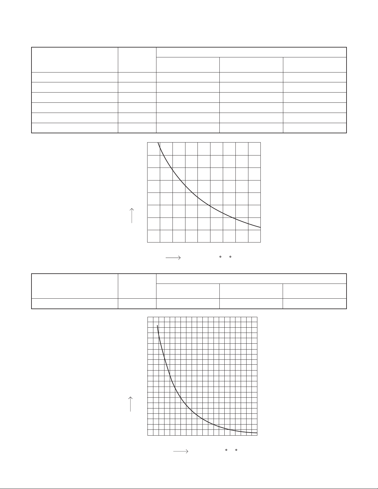
2-3. Other Component Specifications
Sensor Name
Outdoor air temp sensor
Outdoor heat exchanger sensor
AW / AN sensor
BW / BN sensor
CW / CN sensor
DW / DN sensor
Model No.
of sensor
TKS295B
TKS292B
TKS292B
TKS292B
TKS292B
TKS292B
40
35
30
25
20
Resistance (k ohm)
15
10
5
Quantity of Sensor
CU-3KS19NBU CU-4KS24NBU CU-4KS31NBU
1
1
1 / 1
1 / 1
1 / 1
0
1
1
1 / 1
1 / 1
1 / 1
1 / 1
1
1
1 / 1
1 / 1
1 / 1
1 / 1
0
Sensor Name
Compressor temp sensor TKS293B
Model No.
of sensor
200
180
160
140
120
100
Resistance (k ohm)
80
60
40
-
4 5 14 23 32 41 50 59 68
(-20)(-15)(-10) (-5) (0) (5) (10) (15) (20)
Temperature F ( C)
Quantity of Sensor
CU-3KS19NBU CU-4KS24NBU CU-4KS31NBU
11
1
20
0
32 50 68 86 104 122 140 158 176 194
(0) (10) (20) (30) (40) (50) (60)(70) (80) (90)
Temperature F ( C)
20
Page 21

3. DIMENSIONAL DATA
Outdoor Unit CU-3KS19NBU
23-15/16 5-11/32
11-17/32
1-3/8
ID:23/32
2-ID:15/16
15/32
13-19/32
12-19/32(320)
14-17/32
35-7/16(900)
2-15/16
1-13/16
2-1/16
23/32
29-1/8(740)
5-29/32 2-27/32 2-3/4
2-1/32 4-1/2
Wide tube service valve
dia.3/8" (9.52) ×3
Narrow tube service valve
dia.1/4" (6.35) ×3
2-3/4
2-15/16
4-7/16
Unit: inch(mm)
(852-0-0010-11500-0)
21
Page 22

Outdoor Unit CU-4KS24NBU
23-15/16 5-11/32
11-17/32
1-3/8
ID:23/32
2-ID:15/16
15/32
13-19/32
14-17/32
12-19/32(320)
35-7/16(900)
2-15/16
1-13/16
2-1/16
2-13/32
23/32
29-1/8(740)
2-3/4
5-29/32 2-27/32 2-3/4
2-1/32 4-1/2
Wide tube service valve
dia.1/2" (12.70)
Narrow tube service valve
dia.1/4" (6.35)
Wide tube service valve
dia.3/8" (9.52)
2-3/4 2-3/4
2-15/16
4-7/16
×1
×4
×3
Unit: inch(mm)
(852-0-0010-20500-0)
22
Page 23

Outdoor Unit CU-4KS31NBU
23-15/16 5-11/32
11-17/32
1-3/8
ID:23/32
2-ID:15/16
15/32
13-19/32
14-17/32
12-19/32(320)
35-7/16(900)
2-15/16
1-13/16
2-1/16
2-13/32
23/32
35-1/32(890)
2-7/8 2-3/4 2-3/4
5-29/32
2-1/32 4-1/2
Wide tube service valve
dia.1/2" (12.70) ×2
Narrow tube service valve
dia.1/4" (6.35) ×4
Wide tube service valve
dia.3/8" (9.52) ×2
2-3/4 2-3/4
2-15/16
4-7/16
Unit: inch(mm)
(852-0-0010-20600-0)
23
Page 24

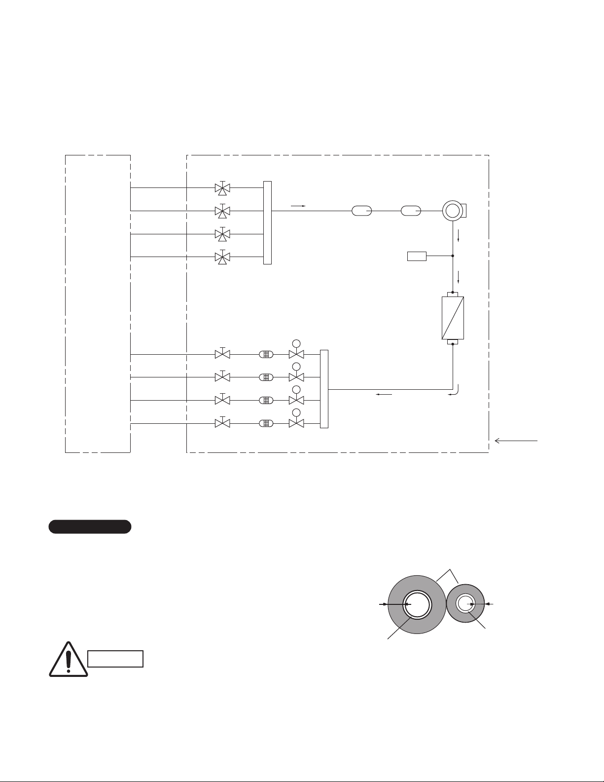
4. REFRIGERANT FLOW DIAGRAM
4-1. Refrigerant Flow Diagram
Outdoor Unit CU-3KS19NBU
Indoor unit Outdoor unit
Service valve on
Wide tube
O.D.3/8"
O.D.3/8"
O.D.3/8"
Narrow tube
O.D.1/4"
O.D.1/4"
O.D.1/4"
wide tube
CW
BW
AW
Header
Service valve on
narrow tube
CN
BN
AN
Strainer Header
Electric
expansion
valve
M
M
M
Sub
accumulator
Main
accumulator
High pressure
switch
H.P.
Compressor
Heat exchanger
Cooling cycle
Insulation of Refrigerant Tubing
IMPORTANT
Because capillary tubing is used in the outdoor unit, both the
wide and narrow tubes of this air conditioner become cold. To
prevent heat loss and wet floors due to dripping of
condensation, both tubes must be well insulated with a
proper insulation material. The thickness of the insulation
should be a min.5/16"(8 mm).
After a tube has been insulated,
CAUTION
never try to bend it into a narrow
curve because it can cause the tube
to break or crack.
24
Thickness:
Min.5/16"(8 mm)
Wide tube
Insulation
Thickness:
Min.5/16"(8 mm)
Narrow tube
Page 25
Outdoor Unit CU-4KS24NBU
Indoor unit Outdoor unit
Service valve on
Wide tube
O.D.1/2"
O.D.3/8"
O.D.3/8"
O.D.3/8"
Narrow tube
O.D.1/4"
O.D.1/4"
O.D.1/4"
O.D.1/4"
wide tube
DW
CW
BW
AW
Service valve on
narrow tube
DN
CN
BN
AN
Header
Electric
expansion
valve
M
M
M
M
Strainer Header
Sub
accumulator
Main
accumulator
High pressure
switch
H.P.
Compressor
Heat exchanger
Cooling cycle
Insulation of Refrigerant Tubing
IMPORTANT
Because capillary tubing is used in the outdoor unit, both the
wide and narrow tubes of this air conditioner become cold. To
prevent heat loss and wet floors due to dripping of
condensation, both tubes must be well insulated with a
proper insulation material. The thickness of the insulation
should be a min.5/16"(8 mm).
After a tube has been insulated,
CAUTION
never try to bend it into a narrow
curve because it can cause the tube
to break or crack.
25
Thickness:
Min.5/16"(8 mm)
Wide tube
Insulation
Thickness:
Min.5/16"(8 mm)
Narrow tube
Page 26

Outdoor Unit CU-4KS31NBU
Indoor unit Outdoor unit
Service valve on
Wide tube
O.D.1/2"
O.D.1/2"
O.D.3/8"
O.D.3/8"
Narrow tube
O.D.1/4"
O.D.1/4"
O.D.1/4"
O.D.1/4"
wide tube
DW
CW
BW
AW
Service valve on
narrow tube
DN
CN
BN
AN
Header
Electric
expansion
valve
M
M
M
M
Strainer Header
Sub
accumulator
Main
accumulator
High pressure
switch
H.P.
Compressor
Heat exchanger
Cooling cycle
Insulation of Refrigerant Tubing
IMPORTANT
Because capillary tubing is used in the outdoor unit, both the
wide and narrow tubes of this air conditioner become cold. To
prevent heat loss and wet floors due to dripping of
condensation, both tubes must be well insulated with a
proper insulation material. The thickness of the insulation
should be a min.5/16"(8 mm).
After a tube has been insulated,
CAUTION
never try to bend it into a narrow
curve because it can cause the tube
to break or crack.
26
Thickness:
Min.5/16"(8 mm)
Wide tube
Insulation
Thickness:
Min.5/16"(8 mm)
Narrow tube
Page 27

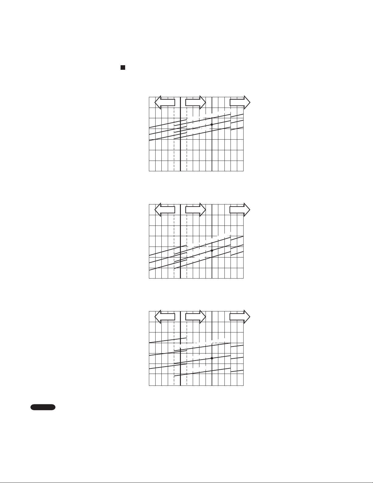
5. PERFORMANCE DATA
5-1. Temperature Charts
5-1-1. Temperature Charts (CU-3KS19NBU)
Outdoor Unit CU-3KS19NBU Indoor Unit CS-MKS7NKU ×1
Cooling Characteristics
(RH : 46%, Indoor fan speed : High fan)
(230V, 60Hz)
(1) Low pressure performance chart
188
(1.3)
psig (MPaG)
174
(1.2)
160
(1.1)
Low pressure at wide tube service valve
146
(1.0)
Lo fan Hi fan HH fan
77
(25)
Indoor air temp. 86°F (30°C)
86
(30)
Outdoor air temperature °F (°C)
80°F (27°C)
75°F (24°C)
95
(35)
(2) Operating current performance chart
Lo fan Hi fan HH fan
5
4
Indoor air temp. 86°F (30°C)
(30)
86
80°F (27°C)
75°F (24°C)
95
(35)
3
Operating current (A)
2
77
(25)
Outdoor air temperature °F (°C)
(3) Indoor discharge air performance chart
104
(40)
104
(40)
68.0(20)
64.4(18)
60.8(16)
57.2(14)
53.6(12)
50.0(10)
46.4( 8)
Indoor discharge air temperature °F (°C)
Lo fan Hi fan HH fan
Indoor air temp. 86°F (30°C)
77
(25)
86
(30)
Outdoor air temperature °F (°C)
95
(35)
80°F (27°C)
75°F (24°C)
104
(40)
NOTE
• This performance chart shows operation of a single wall-mounted indoor unit. The performance chart will vary depending on
the indoor unit type.
• Check each performance value in test-run mode. Electrical performance values represent a combined indoor/outdoor value.
(In this case, be sure to stop all the indoor units where performance is not being checked.)
• The performance is for a tubing length of 24.6t (7.5m). If the tubing length is different, the performance chart will vary.
27
Page 28

Outdoor Unit CU-3KS19NBU Indoor Unit CS-MKS9NKU ×1
Cooling Characteristics
(RH : 46%, Indoor fan speed : High fan)
(230V, 60Hz)
(1) Low pressure performance chart
188
(1.3)
psig (MPaG)
174
(1.2)
160
(1.1)
Low pressure at wide tube service valve
146
(1.0)
Lo fan Hi fan
77
(25)
Indoor air temp. 86°F (30°C)
80°F (27°C)
75°F (24°C)
86
(30)
Outdoor air temperature °F (°C)
95
(35)
(2) Operating current performance chart
Lo fan Hi fan
6
5
4
Operating current (A)
3
77
(25)
Indoor air temp. 86°F (30°C)
80°F (27°C)
75°F (24°C)
86
(30)
Outdoor air temperature °F (°C)
95
(35)
HH fan
HH fan
104
(40)
104
(40)
(3) Indoor discharge air performance chart
68.0(20)
64.4(18)
60.8(16)
57.2(14)
53.6(12)
50.0(10)
46.4( 8)
Indoor discharge air temperature °F (°C)
Lo fan Hi fan
77
(25)
Indoor air temp. 86°F (30°C)
86
(30)
Outdoor air temperature °F (°C)
95
(35)
NOTE
• This performance chart shows operation of a single wall-mounted indoor unit. The performance chart will vary depending on
the indoor unit type.
• Check each performance value in test-run mode. Electrical performance values represent a combined indoor/outdoor value.
(In this case, be sure to stop all the indoor units where performance is not being checked.)
• The performance is for a tubing length of 24.6ft (7.5m). If the tubing length is different, the performance chart will vary.
80°F (27°C)
75°F (24°C)
HH fan
104
(40)
28
Page 29
Outdoor Unit CU-3KS19NBU Indoor Unit CS-MKS12NKU ×1
Cooling Characteristics
(RH : 46%, Indoor fan speed : High fan)
(230V, 60Hz)
(1) Low pressure performance chart
174
(1.2)
psig (MPaG)
160
(1.1)
146
(1.0)
Low pressure at wide tube service valve
132
(0.9)
Lo fan Hi fan
77
(25)
Indoor air temp. 86°F (30°C)
80°F (27°C)
75°F (24°C)
86
(30)
Outdoor air temperature °F (°C)
95
(35)
(2) Operating current performance chart
Lo fan Hi fan
6
5
Indoor air temp. 86°F (30°C)
(30)
86
80°F (27°C)
75°F (24°C)
95
(35)
4
Operating current (A)
3
77
(25)
Outdoor air temperature °F (°C)
HH fan
HH fan
104
(40)
104
(40)
(3) Indoor discharge air performance chart
68.0(20)
64.4(18)
60.8(16)
57.2(14)
53.6(12)
50.0(10)
46.4( 8)
Indoor discharge air temperature °F (°C)
Lo fan Hi fan
77
(25)
Indoor air temp. 86°F (30°C)
80°F (27°C)
75°F (24°C)
86
(30)
Outdoor air temperature °F (°C)
95
(35)
NOTE
• This performance chart shows operation of a single wall-mounted indoor unit. The performance chart will vary depending on
the indoor unit type.
• Check each performance value in test-run mode. Electrical performance values represent a combined indoor/outdoor value.
(In this case, be sure to stop all the indoor units where performance is not being checked.)
• The performance is for a tubing length of 24.6ft (7.5m). If the tubing length is different, the performance chart will vary.
HH fan
104
(40)
29
Page 30

Outdoor Unit CU-3KS19NBU Indoor Unit CS-MKS18NKU ×1
Cooling Characteristics
(RH : 46%, Indoor fan speed : High fan)
(230V, 60Hz)
(1) Low pressure performance chart
174
(1.2)
psig (MPaG)
160
(1.1)
146
(1.0)
Low pressure at wide tube service valve
132
(0.9)
Lo fan Hi fan
77
(25)
Indoor air temp. 86°F (30°C)
80°F (27°C)
75°F (24°C)
86
(30)
Outdoor air temperature °F (°C)
(2) Operating current performance chart
8
Lo fan Hi fan
7
95
(35)
HH fan
HH fan
104
(40)
6
Operating current (A)
5
77
(25)
Indoor air temp. 86°F (30°C)
80°F (27°C)
75°F (24°C)
86
(30)
Outdoor air temperature °F (°C)
95
(35)
104
(40)
(3) Indoor discharge air performance chart
68.0(20)
64.4(18)
60.8(16)
57.2(14)
53.6(12)
50.0(10)
Indoor discharge air temperature °F (°C)
46.4( 8)
Lo fan Hi fan
77
(25)
Indoor air temp. 86°F (30°C)
80°F (27°C)
75°F (24°C)
86
(30)
Outdoor air temperature °F (°C)
95
(35)
NOTE
• This performance chart shows operation of a single wall-mounted indoor unit. The performance chart will vary depending on
the indoor unit type.
• Check each performance value in test-run mode. Electrical performance values represent a combined indoor/outdoor value.
(In this case, be sure to stop all the indoor units where performance is not being checked.)
• The performance is for a tubing length of 24.6ft (7.5m). If the tubing length is different, the performance chart will vary.
HH fan
104
(40)
30
Page 31

Outdoor Unit CU-3KS19NBU Indoor Unit CS-MKS9NB4U ×1
Cooling Characteristics
(RH : 46%, Indoor fan speed : High fan)
(230V, 60Hz)
(1) Low pressure performance chart
174
(1.2)
psig (MPaG)
160
(1.1)
146
(1.0)
Low pressure at wide tube service valve
132
(0.9)
Lo fan Hi fan
77
(25)
Indoor air temp. 86°F (30°C)
Indoor air temp. 86°F (30°C)
80°F (27°C)
80°F (27°C)
75°F (24°C)
75°F (24°C)
86
(30)
Outdoor air temperature °F (°C)
95
(35)
(2) Operating current performance chart
6
Lo fan Hi fan
5
4
Operating current (A)
3
Indoor air temp. 86°F (30°C)
Indoor air temp. 86°F (30°C)
80°F (27°C)
80°F (27°C)
75°F (24°C)
75°F (24°C)
HH fan
HH fan
104
(40)
77
(25)
86
(30)
Outdoor air temperature °F (°C)
95
(35)
104
(40)
(3) Indoor discharge air performance chart
68.0(20)
64.4(18)
60.8(16)
57.2(14)
53.6(12)
50.0(10)
46.4( 8)
Indoor discharge air temperature °F (°C)
Lo fan Hi fan
77
(25)
Indoor air temp. 86°F (30°C)
Indoor air temp. 86°F (30°C)
86
(30)
Outdoor air temperature °F (°C)
95
(35)
NOTE
• This performance chart shows operation of a single wall-mounted indoor unit. The performance chart will vary depending on
the indoor unit type.
• Check each performance value in test-run mode. Electrical performance values represent a combined indoor/outdoor value.
(In this case, be sure to stop all the indoor units where performance is not being checked.)
• The performance is for a tubing length of 24.6ft (7.5m). If the tubing length is different, the performance chart will vary.
80°F (27°C)
80°F (27°C)
75°F (24°C)
75°F (24°C)
HH fan
104
(40)
31
Page 32

Outdoor Unit CU-3KS19NBU Indoor Unit CS-MKS12NB4U ×1
Cooling Characteristics
(RH : 46%, Indoor fan speed : High fan)
(230V, 60Hz)
(1) Low pressure performance chart
174
(1.2)
160
psig (MPaG)
(1.1)
146
(1.0)
132
(0.9)
Low pressure at wide tube service valve
Lo fan Hi fan
Indoor air temp. 86°F (30°C)
80°F (27°C)
75°F (24°C)
HH fan
77
(25)
86
(30)
Outdoor air temperature °F (°C)
95
(35)
(2) Operating current performance chart
Lo fan Hi fan
6
5
Indoor air temp. 86°F (30°C)
(30)
86
80°F (27°C)
75°F (24°C)
95
(35)
4
Operating current (A)
3
77
(25)
Outdoor air temperature °F (°C)
(3) Indoor discharge air performance chart
68.0(20)
64.4(18)
60.8(16)
57.2(14)
53.6(12)
50.0(10)
46.4( 8)
Lo fan Hi fan
Indoor air temp. 86°F (30°C)
80°F (27°C)
75°F (24°C)
HH fan
HH fan
104
(40)
104
(40)
Indoor discharge air temperature °F (°C)
42.8( 6)
77
(25)
86
(30)
Outdoor air temperature °F (°C)
95
(35)
104
(40)
NOTE
• This performance chart shows operation of a single wall-mounted indoor unit. The performance chart will vary depending on
the indoor unit type.
• Check each performance value in test-run mode. Electrical performance values represent a combined indoor/outdoor value.
(In this case, be sure to stop all the indoor units where performance is not being checked.)
• The performance is for a tubing length of 24.6ft (7.5m). If the tubing length is different, the performance chart will vary.
32
Page 33

Outdoor Unit CU-3KS19NBU Indoor Unit CS-KS18NB4UW ×1
Cooling Characteristics
(RH : 46%, Indoor fan speed : High fan)
(230V, 60Hz)
(1) Low pressure performance chart
174
(1.2)
160
psig (MPaG)
(1.1)
146
(1.0)
132
(0.9)
Low pressure at wide tube service valve
Lo fan Hi fan
Indoor air temp. 86°F (30°C)
80°F (27°C)
75°F (24°C)
HH fan
77
(25)
86
(30)
Outdoor air temperature °F (°C)
95
(35)
104
(40)
(2) Operating current performance chart
Lo fan Hi fan
7
6
5
Operating current (A)
4
77
(25)
Indoor air temp. 86°F (30°C)
80°F (27°C)
75°F (24°C)
86
(30)
Outdoor air temperature °F (°C)
95
(35)
HH fan
104
(40)
(3) Indoor discharge air performance chart
68.0(20)
64.4(18)
60.8(16)
57.2(14)
53.6(12)
50.0(10)
46.4( 8)
Indoor discharge air temperature °F (°C)
42.8( 6)
NOTE
• This performance chart shows operation of a single wall-mounted indoor unit. The performance chart will vary depending on
the indoor unit type.
• Check each performance value in test-run mode. Electrical performance values represent a combined indoor/outdoor value.
(In this case, be sure to stop all the indoor units where performance is not being checked.)
• The performance is for a tubing length of 24.6ft (7.5m). If the tubing length is different, the performance chart will vary.
Lo fan Hi fan
77
(25)
Indoor air temp. 86°F (30°C)
80°F (27°C)
75°F (24°C)
86
(30)
Outdoor air temperature °F (°C)
95
(35)
HH fan
104
(40)
33
Page 34

5-1-2. Temperature Charts (CU-4KS24NBU)
Outdoor Unit CU-4KS24NBU Indoor Unit CS-MKS7NKU ×1
Cooling Characteristics
(RH : 46%, Indoor fan speed : High fan)
(230V, 60Hz)
(1) Low pressure performance chart
188
(1.3)
psig (MPaG)
174
(1.2)
160
(1.1)
Low pressure at wide tube service valve
146
(1.0)
Lo fan Hi fan HH fan
Indoor air temp. 86°F (30°C)
77
(25)
86
(30)
Outdoor air temperature °F (°C)
95
(35)
80°F (27°C)
75°F (24°C)
(2) Operating current performance chart
Lo fan Hi fan HH fan
5
4
Indoor air temp. 86°F (30°C)
(30)
86
80°F (27°C)
75°F (24°C)
95
(35)
3
Operating current (A)
2
77
(25)
Outdoor air temperature °F (°C)
(3) Indoor discharge air performance chart
104
(40)
104
(40)
68.0(20)
64.4(18)
60.8(16)
57.2(14)
53.6(12)
50.0(10)
46.4( 8)
Indoor discharge air temperature °F (°C)
Lo fan Hi fan HH fan
Indoor air temp. 86°F (30°C)
77
(25)
86
(30)
Outdoor air temperature °F (°C)
95
(35)
80°F (27°C)
75°F (24°C)
104
(40)
NOTE
• This performance chart shows operation of a single wall-mounted indoor unit. The performance chart will vary depending on
the indoor unit type.
• Check each performance value in test-run mode. Electrical performance values represent a combined indoor/outdoor value.
(In this case, be sure to stop all the indoor units where performance is not being checked.)
• The performance is for a tubing length of 24.6t (7.5m). If the tubing length is different, the performance chart will vary.
34
Page 35

Outdoor Unit CU-4KS24NBU Indoor Unit CS-MKS9NKU ×1
Cooling Characteristics
(RH : 46%, Indoor fan speed : High fan)
(230V, 60Hz)
(1) Low pressure performance chart
188
(1.3)
psig (MPaG)
174
(1.2)
160
(1.1)
Low pressure at wide tube service valve
146
(1.0)
Lo fan Hi fan
77
(25)
Indoor air temp. 86°F (30°C)
80°F (27°C)
75°F (24°C)
86
(30)
Outdoor air temperature °F (°C)
95
(35)
(2) Operating current performance chart
Lo fan Hi fan
6
5
4
Operating current (A)
3
77
(25)
Outdoor air temperature °F (°C)
Indoor air temp. 86°F (30°C)
80°F (27°C)
75°F (24°C)
86
(30)
95
(35)
HH fan
HH fan
104
(40)
104
(40)
(3) Indoor discharge air performance chart
68.0(20)
64.4(18)
60.8(16)
57.2(14)
53.6(12)
50.0(10)
46.4( 8)
Indoor discharge air temperature °F (°C)
Lo fan Hi fan
77
(25)
Indoor air temp. 86°F (30°C)
86
(30)
Outdoor air temperature °F (°C)
95
(35)
NOTE
• This performance chart shows operation of a single wall-mounted indoor unit. The performance chart will vary depending on
the indoor unit type.
• Check each performance value in test-run mode. Electrical performance values represent a combined indoor/outdoor value.
(In this case, be sure to stop all the indoor units where performance is not being checked.)
• The performance is for a tubing length of 24.6ft (7.5m). If the tubing length is different, the performance chart will vary.
80°F (27°C)
75°F (24°C)
HH fan
104
(40)
35
Page 36

Outdoor Unit CU-4KS24NBU Indoor Unit CS-MKS12NKU ×1
Cooling Characteristics
(RH : 46%, Indoor fan speed : High fan)
(230V, 60Hz)
(1) Low pressure performance chart
174
(1.2)
psig (MPaG)
160
(1.1)
146
(1.0)
Low pressure at wide tube service valve
132
(0.9)
Lo fan Hi fan
77
(25)
Indoor air temp. 86°F (30°C)
80°F (27°C)
75°F (24°C)
86
(30)
Outdoor air temperature °F (°C)
95
(35)
(2) Operating current performance chart
Lo fan Hi fan
6
5
Indoor air temp. 86°F (30°C)
(30)
86
80°F (27°C)
75°F (24°C)
95
(35)
4
Operating current (A)
3
77
(25)
Outdoor air temperature °F (°C)
HH fan
HH fan
104
(40)
104
(40)
(3) Indoor discharge air performance chart
68.0(20)
64.4(18)
60.8(16)
57.2(14)
53.6(12)
50.0(10)
46.4( 8)
Indoor discharge air temperature °F (°C)
Lo fan Hi fan
77
(25)
Indoor air temp. 86°F (30°C)
80°F (27°C)
75°F (24°C)
86
(30)
Outdoor air temperature °F (°C)
95
(35)
NOTE
• This performance chart shows operation of a single wall-mounted indoor unit. The performance chart will vary depending on
the indoor unit type.
• Check each performance value in test-run mode. Electrical performance values represent a combined indoor/outdoor value.
(In this case, be sure to stop all the indoor units where performance is not being checked.)
• The performance is for a tubing length of 24.6ft (7.5m). If the tubing length is different, the performance chart will vary.
HH fan
104
(40)
36
Page 37

Outdoor Unit CU-4KS24NBU Indoor Unit CS-MKS18NKU ×1
Cooling Characteristics
(RH : 46%, Indoor fan speed : High fan)
(230V, 60Hz)
(1) Low pressure performance chart
174
(1.2)
psig (MPaG)
160
(1.1)
146
(1.0)
Low pressure at wide tube service valve
132
(0.9)
Lo fan Hi fan
77
(25)
Indoor air temp. 86°F (30°C)
80°F (27°C)
75°F (24°C)
86
(30)
Outdoor air temperature °F (°C)
(2) Operating current performance chart
8
Lo fan Hi fan
7
95
(35)
HH fan
HH fan
104
(40)
6
Operating current (A)
5
77
(25)
Outdoor air temperature °F (°C)
Indoor air temp. 86°F (30°C)
80°F (27°C)
75°F (24°C)
86
(30)
95
(35)
104
(40)
(3) Indoor discharge air performance chart
68.0(20)
64.4(18)
60.8(16)
57.2(14)
53.6(12)
50.0(10)
Indoor discharge air temperature °F (°C)
46.4( 8)
Lo fan Hi fan
77
(25)
Indoor air temp. 86°F (30°C)
80°F (27°C)
75°F (24°C)
86
(30)
Outdoor air temperature °F (°C)
95
(35)
NOTE
• This performance chart shows operation of a single wall-mounted indoor unit. The performance chart will vary depending on
the indoor unit type.
• Check each performance value in test-run mode. Electrical performance values represent a combined indoor/outdoor value.
(In this case, be sure to stop all the indoor units where performance is not being checked.)
• The performance is for a tubing length of 24.6ft (7.5m). If the tubing length is different, the performance chart will vary.
HH fan
104
(40)
37
Page 38

Outdoor Unit CU-4KS24NBU Indoor Unit CS-MKS24NKU ×1
Cooling Characteristics
(RH : 46%, Indoor fan speed : High fan)
(230V, 60Hz)
(1) Low pressure performance chart
174
(1.2)
psig (MPaG)
160
(1.1)
146
(1.0)
Low pressure at wide tube service valve
132
(0.9)
Lo fan Hi fan
77
(25)
Indoor air temp. 86°F (30°C)
86
(30)
Outdoor air temperature °F (°C)
75°F (24°C)
95
(35)
80°F (27°C)
(2) Operating current performance chart
9
Lo fan Hi fan
8
7
Operating current (A)
6
Indoor air temp. 86°F (30°C)
80°F (27°C)
75°F (24°C)
HH fan
HH fan
104
(40)
77
(25)
86
(30)
Outdoor air temperature °F (°C)
95
(35)
104
(40)
(3) Indoor discharge air performance chart
68.0(20)
64.4(18)
60.8(16)
57.2(14)
53.6(12)
50.0(10)
Indoor discharge air temperature °F (°C)
46.4( 8)
Lo fan Hi fan
77
(25)
Indoor air temp. 86°F (30°C)
80°F (27°C)
75°F (24°C)
86
(30)
Outdoor air temperature °F (°C)
95
(35)
NOTE
• This performance chart shows operation of a single wall-mounted indoor unit. The performance chart will vary depending on
the indoor unit type.
• Check each performance value in test-run mode. Electrical performance values represent a combined indoor/outdoor value.
(In this case, be sure to stop all the indoor units where performance is not being checked.)
• The performance is for a tubing length of 24.6ft (7.5m). If the tubing length is different, the performance chart will vary.
HH fan
104
(40)
38
Page 39

Outdoor Unit CU-4KS24NBU Indoor Unit CS-MKS9NB4U ×1
Cooling Characteristics
(RH : 46%, Indoor fan speed : High fan)
(230V, 60Hz)
(1) Low pressure performance chart
174
(1.2)
psig (MPaG)
160
(1.1)
146
(1.0)
Low pressure at wide tube service valve
132
(0.9)
Lo fan Hi fan
77
(25)
Indoor air temp. 86°F (30°C)
Indoor air temp. 86°F (30°C)
80°F (27°C)
80°F (27°C)
75°F (24°C)
75°F (24°C)
86
(30)
Outdoor air temperature °F (°C)
95
(35)
(2) Operating current performance chart
6
Lo fan Hi fan
5
4
Operating current (A)
3
Indoor air temp. 86°F (30°C)
Indoor air temp. 86°F (30°C)
80°F (27°C)
80°F (27°C)
75°F (24°C)
75°F (24°C)
HH fan
HH fan
104
(40)
77
(25)
86
(30)
Outdoor air temperature °F (°C)
95
(35)
104
(40)
(3) Indoor discharge air performance chart
68.0(20)
64.4(18)
60.8(16)
57.2(14)
53.6(12)
50.0(10)
46.4( 8)
Indoor discharge air temperature °F (°C)
Lo fan Hi fan
77
(25)
Indoor air temp. 86°F (30°C)
Indoor air temp. 86°F (30°C)
86
(30)
Outdoor air temperature °F (°C)
95
(35)
NOTE
• This performance chart shows operation of a single wall-mounted indoor unit. The performance chart will vary depending on
the indoor unit type.
• Check each performance value in test-run mode. Electrical performance values represent a combined indoor/outdoor value.
(In this case, be sure to stop all the indoor units where performance is not being checked.)
• The performance is for a tubing length of 24.6ft (7.5m). If the tubing length is different, the performance chart will vary.
80°F (27°C)
80°F (27°C)
75°F (24°C)
75°F (24°C)
HH fan
104
(40)
39
Page 40

Outdoor Unit CU-4KS24NBU Indoor Unit CS-MKS12NB4U ×1
Cooling Characteristics
(RH : 46%, Indoor fan speed : High fan)
(230V, 60Hz)
(1) Low pressure performance chart
174
(1.2)
160
psig (MPaG)
(1.1)
146
(1.0)
132
(0.9)
Low pressure at wide tube service valve
Lo fan Hi fan
Indoor air temp. 86°F (30°C)
80°F (27°C)
75°F (24°C)
HH fan
77
(25)
86
(30)
Outdoor air temperature °F (°C)
95
(35)
(2) Operating current performance chart
Lo fan Hi fan
6
5
Indoor air temp. 86°F (30°C)
(30)
86
80°F (27°C)
75°F (24°C)
95
(35)
4
Operating current (A)
3
77
(25)
Outdoor air temperature °F (°C)
(3) Indoor discharge air performance chart
68.0(20)
64.4(18)
60.8(16)
57.2(14)
53.6(12)
50.0(10)
46.4( 8)
Lo fan Hi fan
Indoor air temp. 86°F (30°C)
80°F (27°C)
75°F (24°C)
HH fan
HH fan
104
(40)
104
(40)
Indoor discharge air temperature °F (°C)
42.8( 6)
77
(25)
86
(30)
Outdoor air temperature °F (°C)
95
(35)
104
(40)
NOTE
• This performance chart shows operation of a single wall-mounted indoor unit. The performance chart will vary depending on
the indoor unit type.
• Check each performance value in test-run mode. Electrical performance values represent a combined indoor/outdoor value.
(In this case, be sure to stop all the indoor units where performance is not being checked.)
• The performance is for a tubing length of 24.6ft (7.5m). If the tubing length is different, the performance chart will vary.
40
Page 41

Outdoor Unit CU-4KS24NBU Indoor Unit CS-KS18NB4UW ×1
Cooling Characteristics
(RH : 46%, Indoor fan speed : High fan)
(230V, 60Hz)
(1) Low pressure performance chart
174
(1.2)
160
psig (MPaG)
(1.1)
146
(1.0)
132
(0.9)
Low pressure at wide tube service valve
Lo fan Hi fan
Indoor air temp. 86°F (30°C)
80°F (27°C)
75°F (24°C)
HH fan
77
(25)
86
(30)
Outdoor air temperature °F (°C)
95
(35)
104
(40)
(2) Operating current performance chart
Lo fan Hi fan
7
6
5
Operating current (A)
4
77
(25)
Indoor air temp. 86°F (30°C)
80°F (27°C)
75°F (24°C)
86
(30)
Outdoor air temperature °F (°C)
95
(35)
HH fan
104
(40)
(3) Indoor discharge air performance chart
68.0(20)
64.4(18)
60.8(16)
57.2(14)
53.6(12)
50.0(10)
46.4( 8)
Indoor discharge air temperature °F (°C)
42.8( 6)
NOTE
• This performance chart shows operation of a single wall-mounted indoor unit. The performance chart will vary depending on
the indoor unit type.
• Check each performance value in test-run mode. Electrical performance values represent a combined indoor/outdoor value.
(In this case, be sure to stop all the indoor units where performance is not being checked.)
• The performance is for a tubing length of 24.6ft (7.5m). If the tubing length is different, the performance chart will vary.
Lo fan Hi fan
77
(25)
Indoor air temp. 86°F (30°C)
80°F (27°C)
75°F (24°C)
86
(30)
Outdoor air temperature °F (°C)
95
(35)
HH fan
104
(40)
41
Page 42

5-1-3. Temperature Charts (CU-4KS31NBU)
Outdoor Unit CU-4KS31NBU Indoor Unit CS-MKS7NKU ×1
Cooling Characteristics
(RH : 46%, Indoor fan speed : High fan)
(230V, 60Hz)
(1) Low pressure performance chart
174
(1.2)
psig (MPaG)
146
(1.0)
118
(0.8)
Low pressure at wide tube service valve
(0.6)
Lo fan Hi fan Hi fan HH fan
Indoor air temp. 86°F (30°C)
90
77
(25)
86
(30)
Outdoor air temperature °F (°C)
80°F (27°C)
75°F (24°C)
95
(35)
(2) Operating current performance chart
5
Lo fan Hi fan Hi fan HH fan
4
Indoor air temp. 86°F (30°C)
Operating current (A)
3
77
(25)
86
(30)
Outdoor air temperature °F (°C)
95
(35)
104
(40)
80°F (27°C)
75°F (24°C)
104
(40)
(3) Indoor discharge air performance chart
Lo fan Hi fan Hi fan HH fan
68.0(20)
64.4(18)
60.8(16)
57.2(14)
53.6(12)
50.0(10)
Indoor discharge air temperature °F (°C)
46.4( 8)
77
(25)
Outdoor air temperature °F (°C)
Indoor air temp. 86°F (30°C)
86
(30)
80°F (27°C)
75°F (24°C)
95
(35)
104
(40)
NOTE
• This performance chart shows operation of a single wall-mounted indoor unit. The performance chart will vary depending on
the indoor unit type.
• Check each performance value in test-run mode. Electrical performance values represent a combined indoor/outdoor value.
(In this case, be sure to stop all the indoor units where performance is not being checked.)
• The performance is for a tubing length of 24.6ft (7.5m). If the tubing length is different, the performance chart will vary.
42
Page 43

Outdoor Unit CU-4KS31NBU Indoor Unit CS-MKS9NKU ×1
Cooling Characteristics
(RH : 46%, Indoor fan speed : High fan)
(230V, 60Hz)
(1) Low pressure performance chart
174
(1.2)
psig (MPaG)
146
(1.0)
118
(0.8)
Low pressure at wide tube service valve
(0.6)
Lo fan Hi fan Hi fan HH fan
Indoor air temp. 86°F (30°C)
80°F (27°C)
75°F (24°C)
90
77
(25)
86
(30)
Outdoor air temperature °F (°C)
95
(35)
(2) Operating current performance chart
5
Lo fan Hi fan Hi fan HH fan
4
Indoor air temp. 86°F (30°C)
Operating current (A)
3
77
(25)
86
(30)
Outdoor air temperature °F (°C)
95
(35)
104
(40)
80°F (27°C)
75°F (24°C)
104
(40)
(3) Indoor discharge air performance chart
Lo fan Hi fan Hi fan HH fan
68.0(20)
64.4(18)
60.8(16)
57.2(14)
53.6(12)
50.0(10)
46.4( 8)
Indoor discharge air temperature °F (°C)
77
(25)
Outdoor air temperature °F (°C)
Indoor air temp. 86°F (30°C)
80°F (27°C)
75°F (24°C)
86
(30)
95
(35)
104
(40)
NOTE
• This performance chart shows operation of a single wall-mounted indoor unit. The performance chart will vary depending on
the indoor unit type.
• Check each performance value in test-run mode. Electrical performance values represent a combined indoor/outdoor value.
(In this case, be sure to stop all the indoor units where performance is not being checked.)
• The performance is for a tubing length of 24.6ft (7.5m). If the tubing length is different, the performance chart will vary.
43
Page 44

Outdoor Unit CU-4KS31NBU Indoor Unit CS-MKS12NKU ×1
Cooling Characteristics
(RH : 46%, Indoor fan speed : High fan)
(230V, 60Hz)
(1) Low pressure performance chart
174
(1.2)
psig (MPaG)
146
(1.0)
118
(0.8)
Low pressure at wide tube service valve
(0.6)
Lo fan Hi fan Hi fan HH fan
Indoor air temp. 86°F (30°C)
80°F (27°C)
75°F (24°C)
90
77
(25)
86
(30)
Outdoor air temperature °F (°C)
95
(35)
(2) Operating current performance chart
6
Lo fan Hi fan Hi fan HH fan
95
(35)
6°F (30°C)
5
4
Operating current (A)
3
77
(25)
Outdoor air temperature °F (°C)
Indoor air temp. 8
86
(30)
104
(40)
80°F (27°C)
75°F (24°C)
104
(40)
(3) Indoor discharge air performance chart
Lo fan Hi fan Hi fan HH fan
68.0(20)
64.4(18)
60.8(16)
57.2(14)
53.6(12)
50.0(10)
46.4( 8)
Indoor discharge air temperature °F (°C)
77
(25)
Outdoor air temperature °F (°C)
Indoor air temp. 86°F (30°C)
86
(30)
80°F (27°C)
75°F (24°C)
95
(35)
104
(40)
NOTE
• This performance chart shows operation of a single wall-mounted indoor unit. The performance chart will vary depending on
the indoor unit type.
• Check each performance value in test-run mode. Electrical performance values represent a combined indoor/outdoor value.
(In this case, be sure to stop all the indoor units where performance is not being checked.)
• The performance is for a tubing length of 24.6ft (7.5m). If the tubing length is different, the performance chart will vary.
44
Page 45

Outdoor Unit CU-4KS31NBU Indoor Unit CS-MKS18NKU ×1
Cooling Characteristics
(RH : 46%, Indoor fan speed : High fan)
(230V, 60Hz)
(1) Low pressure performance chart
174
(1.2)
psig (MPaG)
146
(1.0)
Indoor air temp. 86°F (30°C)
118
(0.8)
Low pressure at wide tube service valve
90
(0.6)
77
(25)
80°F (27°C)
75°F (24°C)
86
(30)
Outdoor air temperature °F (°C)
Lo fan Hi fan
95
(35)
(2) Operating current performance chart
9
8
7
6
Operating current (A)
5
4
77
(25)
Outdoor air temperature °F (°C)
80°F (27°C)
Indoor air temp. 86°F (30°C)
75°F (24°C)
86
(30)
Lo fan Hi fan
95
(35)
104
(40)
104
(40)
(3) Indoor discharge air performance chart
Lo fan Hi fan
68.0(20)
64.4(18)
60.8(16)
57.2(14)
53.6(12)
50.0(10)
46.4( 8)
Indoor discharge air temperature °F (°C)
77
(25)
Indoor air temp. 86°F (30°C)
86
(30)
Outdoor air temperature °F (°C)
80°F (27°C)
75°F (24°C)
95
(35)
104
(40)
NOTE
• This performance chart shows operation of a single wall-mounted indoor unit. The performance chart will vary depending on
the indoor unit type.
• Check each performance value in test-run mode. Electrical performance values represent a combined indoor/outdoor value.
(In this case, be sure to stop all the indoor units where performance is not being checked.)
• The performance is for a tubing length of 24.6ft (7.5m). If the tubing length is different, the performance chart will vary.
45
Page 46

Outdoor Unit CU-4KS31NBU Indoor Unit CS-MKS24NKU ×1
Cooling Characteristics
(RH : 46%, Indoor fan speed : High fan)
(230V, 60Hz)
(1) Low pressure performance chart
174
(1.2)
psig (MPaG)
146
(1.0)
118
(0.8)
Low pressure at wide tube service valve
90
(0.6)
77
(25)
Indoor air temp. 86°F (30°C)
80°F (27°C)
75°F (24°C)
86
(30)
Outdoor air temperature °F (°C)
Lo fan Hi fan
95
(35)
(2) Operating current performance chart
12
11
10
Operating current (A)
9
8
77
(25)
Outdoor air temperature °F (°C)
Indoor air temp. 86°F (30°C)
80°F (27°C)
75°F (24°C)
86
(30)
Lo fan Hi fan
95
(35)
104
(40)
104
(40)
(3) Indoor discharge air performance chart
Lo fan Hi fan
68.0(20)
64.4(18)
60.8(16)
57.2(14)
53.6(12)
50.0(10)
46.4( 8)
Indoor discharge air temperature °F (°C)
77
(25)
Outdoor air temperature °F (°C)
Indoor air temp. 86°F (30°C)
86
(30)
(35)
80°F (27°C)
75°F (24°C)
95
104
(40)
NOTE
• This performance chart shows operation of a single wall-mounted indoor unit. The performance chart will vary depending on
the indoor unit type.
• Check each performance value in test-run mode. Electrical performance values represent a combined indoor/outdoor value.
(In this case, be sure to stop all the indoor units where performance is not being checked.)
• The performance is for a tubing length of 24.6ft (7.5m). If the tubing length is different, the performance chart will vary.
46
Page 47

Outdoor Unit CU-4KS31NBU Indoor Unit CS-MKS9NB4U ×1
Cooling Characteristics
(RH : 46%, Indoor fan speed : High fan)
(230V, 60Hz)
(1) Low pressure performance chart
174
(1.2)
psig (MPaG)
146
(1.0)
118
(0.8)
Low pressure at wide tube service valve
90
(0.6)
Lo fan Hi fan Hi fan HH fan
Indoor air temp. 86°F (30°C)
80°F (27°C)
75°F (24°C)
77
(25)
86
(30)
Outdoor air temperature °F (°C)
95
(35)
(2) Operating current performance chart
Lo fan Hi fan Hi fan HH fan
5
Operating current (A)
4
Indoor air temp. 86°F (30°C)
104
(40)
80°F (27°C)
75°F (24°C)
77
(25)
86
(30)
Outdoor air temperature °F (°C)
95
(35)
104
(40)
(3) Indoor discharge air performance chart
68.0(20)
64.4(18)
60.8(16)
57.2(14)
53.6(12)
50.0(10)
46.4( 8)
42.8( 6)
Indoor discharge air temperature °F (°C)
NOTE
• This performance chart shows operation of a single wall-mounted indoor unit. The performance chart will vary depending on
the indoor unit type.
• Check each performance value in test-run mode. Electrical performance values represent a combined indoor/outdoor value.
(In this case, be sure to stop all the indoor units where performance is not being checked.)
• The performance is for a tubing length of 24.6ft (7.5m). If the tubing length is different, the performance chart will vary.
Lo fan Hi fan Hi fan HH fan
Indoor air temp. 86°F (30°C)
80°F (27°C)
75°F (24°C)
77
(25)
86
(30)
Outdoor air temperature °F (°C)
95
(35)
104
(40)
47
Page 48

Outdoor Unit CU-4KS31NBU Indoor Unit CS-MKS12NB4U ×1
Cooling Characteristics
(RH : 46%, Indoor fan speed : High fan)
(230V, 60Hz)
(1) Low pressure performance chart
174
(1.2)
psig (MPaG)
146
(1.0)
118
(0.8)
Low pressure at wide tube service valve
90
(0.6)
Lo fan Hi fan Hi fan HH fan
Indoor air temp. 86°F (30°C)
80°F (27°C)
75°F (24°C)
77
(25)
86
(30)
Outdoor air temperature °F (°C)
95
(35)
(2) Operating current performance chart
Lo fan Hi fan Hi fan HH fan
6
5
Operating current (A)
4
Indoor air temp. 86°F (30°C)
104
(40)
80°F (27°C)
75°F (24°C)
77
(25)
86
(30)
Outdoor air temperature °F (°C)
95
(35)
104
(40)
(3) Indoor discharge air performance chart
68.0(20)
64.4(18)
60.8(16)
57.2(14)
53.6(12)
50.0(10)
46.4( 8)
Indoor discharge air temperature °F (°C)
42.8( 6)
NOTE
• This performance chart shows operation of a single wall-mounted indoor unit. The performance chart will vary depending on
the indoor unit type.
• Check each performance value in test-run mode. Electrical performance values represent a combined indoor/outdoor value.
(In this case, be sure to stop all the indoor units where performance is not being checked.)
• The performance is for a tubing length of 24.6ft (7.5m). If the tubing length is different, the performance chart will vary.
Lo fan Hi fan Hi fan HH fan
77
(25)
Indoor air temp. 86°F (30°C)
86
(30)
Outdoor air temperature °F (°C)
80°F (27°C)
75°F (24°C)
95
(35)
104
(40)
48
Page 49

Outdoor Unit CU-4KS31NBU Indoor Unit CS-KS18NB4UW ×1
Cooling Characteristics
(RH : 46%, Indoor fan speed : High fan)
(230V, 60Hz)
(1) Low pressure performance chart
174
(1.2)
psig (MPaG)
146
(1.0)
Indoor air temp. 86°F (30°C)
118
(0.8)
Low pressure at wide tube service valve
90
(0.6)
77
(25)
80°F (27°C)
75°F (24°C)
86
(30)
Outdoor air temperature °F (°C)
Lo fan Hi fan
95
(35)
(2) Operating current performance chart
9
8
7
6
Operating current (A)
5
80°F (27°C)
Indoor air temp. 86°F (30°C)
75°F (24°C)
Lo fan Hi fan
104
(40)
77
(25)
86
(30)
Outdoor air temperature °F (°C)
95
(35)
104
(40)
(3) Indoor discharge air performance chart
64.4(18)
60.8(16)
57.2(14)
53.6(12)
50.0(10)
46.4( 8)
42.8( 6)
39.2( 4)
Indoor discharge air temperature °F (°C)
77
(25)
Indoor air temp. 86°F (30°C)
86
(30)
Outdoor air temperature °F (°C)
NOTE
• This performance chart shows operation of a single wall-mounted indoor unit. The performance chart will vary depending on
the indoor unit type.
• Check each performance value in test-run mode. Electrical performance values represent a combined indoor/outdoor value.
(In this case, be sure to stop all the indoor units where performance is not being checked.)
• The performance is for a tubing length of 24.6ft (7.5m). If the tubing length is different, the performance chart will vary.
Lo fan Hi fan
80°F (27°C)
75°F (24°C)
95
(35)
104
(40)
49
Page 50

5-2. Cooling Capacity
Outdoor Unit : CU-3KS19NBU
Indoor Unit : CS-MKS9NKU × 3
Power Supply : 230V Single Phase 60Hz
< Cooling Capacity >
RATING CAPACITY: 18,800 BTU/h AIR FLOW RATE: 777 CFM
INDOOR OUTDOOR
ENT. TEMP.
WB DB 65 75 85 95 105 115
59 76 (24.4) SHC 18,800 18,230 17,540 16,990 16,170 15,290
(15.0) 80 (26.7) SHC 18,880 18,230 17,540 16,990 16,170 15,290
63 76 (24.4) SHC 15,940 15,630 15,330 15,030 14,730 14,430
(17.2) 80 (26.7) SHC 18,650 18,350 18,050 17,880 17,030 16,120
o
F (oC) AMBIENT TEMP. oF (oC)
TC 18,880 18,230 17,540 16,990 16,170 15,290
72 (22.2) SHC 16,240 15,940 15,630 15,330 15,030 14,580
84 (28.9) SHC 18,880 18,230 17,540 16,990 16,170 15,290
88 (31.1) SHC 18,880 18,230 17,540 16,990 16,170 15,290
TC 19,800 19,130 18,420 17,880 17,030 16,120
72 (22.2) SHC 13,220 12,920 12,620 12,470 12,010 11,710
84 (28.9) SHC 19,800 19,130 18,420 17,880 17,030 16,120
88 (31.1) SHC 19,800 19,130 18,420 17,880 17,030 16,120
TC 20,730 20,050 19,320 # 18,800 17,920 16,970
(18.3) (23.9) (29.4) (35.0) (40.6) (46.1)
72 (22.2) SHC 10,200 9,900 9,750 9,450 9,150 8,840
67 76 (24.4) SHC 12,920 12,620 12,310 12,160 11,860 11,560
(19.4) 80 (26.7) SHC 15,630 15,480 15,180 15,030 14,580 14,280
84 (28.9) SHC 18,350 18,050 17,900 17,600 17,290 16,970
88 (31.1) SHC 20,730 20,050 19,320 18,800 17,920 16,970
TC 21,650 20,970 20,220 19,730 18,830 17,850
72 (22.2) SHC 7,030 6,880 6,580 6,430 6,130 5,830
71 76 (24.4) SHC 9,750 9,450 9,300 9,000 8,690 8,390
(21.7) 80 (26.7) SHC 12,470 12,310 12,010 11,860 11,560 11,260
84 (28.9) SHC 15,180 15,030 14,730 14,580 14,280 13,970
88 (31.1) SHC 17,900 17,600 17,440 17,140 16,840 16,540
TC 22,470 21,780 21,020 20,570 19,650 18,620
75 76 (24.4) SHC 6,580 6,430 6,280 6,130 5,830 5,530
(23.9) 80 (26.7) SHC 9,450 9,300 9,000 8,840 8,540 8,240
84 (28.9) SHC 12,160 11,860 11,710 11,560 11,260 10,960
88 (31.1) SHC 14,880 14,580 14,430 14,280 13,970 13,670
TC : Total Cooling Capacity (BTU/h) SHC : Sensible Heat Capacity (BTU/h)
NOTE
1.
Rating conditions (#)
: Indoor Unit Entering Air Temp. 80 °F (26.7 °C) DB / 67 °F (19.4 °C) WB
: Outdoor Ambient Temp. 95 °F (35 °C) DB
2.
Above data does not take Freeze Prevention Protection during cooling operation into account.
For this reason, the value may vary from the actual cooling characteristics.
3. Above data represents the value when the operation frequency of a compressor is fixed.
50
Page 51

Outdoor Unit : CU-3KS19NBU
Indoor Unit : CS-MKS12NB4U × 3
Power Supply : 230V Single Phase 60Hz
< Cooling Capacity >
RATING CAPACITY: 18,300 BTU/h AIR FLOW RATE: 706 CFM
INDOOR OUTDOOR
ENT. TEMP.
WB DB 65 75 85 95 105 115
59 76 (24.4) SHC 17,370 17,100 16,820 16,550 15,760 14,900
(15.0) 80 (26.7) SHC 18,370 17,750 17,080 16,550 15,760 14,900
63 76 (24.4) SHC 14,770 14,490 14,220 13,940 13,670 13,260
(17.2) 80 (26.7) SHC 17,230 16,960 16,690 16,410 16,140 15,710
o
F (oC) AMBIENT TEMP. oF (oC)
TC 18,370 17,750 17,080 16,550 15,760 14,900
72 (22.2) SHC 15,040 14,770 14,490 14,220 13,940 13,530
84 (28.9) SHC 18,370 17,750 17,080 16,550 15,760 14,900
88 (31.1) SHC 18,370 17,750 17,080 16,550 15,760 14,900
TC 19,260 18,620 17,930 17,410 16,590 15,710
72 (22.2) SHC 12,430 12,160 11,890 11,610 11,340 10,930
84 (28.9) SHC 19,260 18,620 17,930 17,410 16,590 15,710
88 (31.1) SHC 19,260 18,620 17,930 17,410 16,590 15,710
TC 20,150 19,500 18,800 # 18,300 17,450 16,540
(18.3) (23.9) (29.4) (35.0) (40.6) (46.1)
72 (22.2) SHC 9,830 9,550 9,280 9,140 8,730 8,460
67 76 (24.4) SHC 12,160 11,890 11,610 11,470 11,060 10,790
(19.4) 80 (26.7) SHC 14,630 14,350 14,080 13,810 13,530 13,260
84 (28.9) SHC 16,960 16,690 16,410 16,270 15,860 15,590
88 (31.1) SHC 19,290 19,020 18,740 18,300 17,450 16,540
TC 21,050 20,390 19,670 19,200 18,330 17,390
72 (22.2) SHC 6,950 6,810 6,540 6,400 5,990 5,710
71 76 (24.4) SHC 9,280 9,140 8,870 8,730 8,320 8,040
(21.7) 80 (26.7) SHC 11,750 11,470 11,340 11,060 10,790 10,510
84 (28.9) SHC 14,080 13,940 13,670 13,530 13,120 12,850
88 (31.1) SHC 16,410 16,270 16,000 15,860 15,450 15,180
TC 21,830 21,170 20,440 20,010 19,120 18,040
75 76 (24.4) SHC 6,540 6,400 6,120 5,990 5,710 5,440
(23.9) 80 (26.7) SHC 9,000 8,870 8,590 8,460 8,180 7,910
84 (28.9) SHC 11,340 11,200 10,930 10,790 10,510 10,240
88 (31.1) SHC 13,670 13,530 13,260 13,120 12,850 12,570
TC : Total Cooling Capacity (BTU/h) SHC : Sensible Heat Capacity (BTU/h)
NOTE
1.
Rating conditions (#)
: Indoor Unit Entering Air Temp. 80 °F (26.7 °C) DB / 67 °F (19.4 °C) WB
: Outdoor Ambient Temp. 95 °F (35 °C) DB
2.
Above data does not take Freeze Prevention Protection during cooling operation into account.
For this reason, the value may vary from the actual cooling characteristics.
3. Above data represents the value when the operation frequency of a compressor is fixed.
51
Page 52

Outdoor Unit : CU-4KS24NBU
Indoor Unit : CS-MKS9NKU × 3
Power Supply : 230V Single Phase 60Hz
< Cooling Capacity >
RATING CAPACITY: 25,400 BTU/h AIR FLOW RATE: 777 CFM
INDOOR OUTDOOR
ENT. TEMP.
WB DB 65 75 85 95 105 115
59 76 (24.4) SHC 21,970 21,670 21,220 20,910 18,800 14,000
(15.0) 80 (26.7) SHC 24,840 24,530 23,960 23,340 18,890 14,000
63 76 (24.4) SHC 18,950 18,500 18,200 17,900 15,630 13,670
(17.2) 80 (26.7) SHC 21,820 21,370 20,910 20,610 18,500 14,270
o
F (oC) AMBIENT TEMP. oF (oC)
TC 25,520 24,880 23,960 23,340 18,890 14,000
72 (22.2) SHC 19,410 19,100 18,650 18,350 16,240 13,970
84 (28.9) SHC 25,520 24,880 23,960 23,340 18,890 14,000
88 (31.1) SHC 25,520 24,880 23,960 23,340 18,890 14,000
TC 26,760 25,900 24,950 24,370 19,290 14,270
72 (22.2) SHC 16,240 15,940 15,480 15,180 13,070 10,960
84 (28.9) SHC 24,380 24,080 23,630 23,330 19,290 14,270
88 (31.1) SHC 26,760 25,900 24,950 24,370 19,290 14,270
TC 27,750 26,880 25,910 # 25,400 19,630 14,500
(18.3) (23.9) (29.4) (35.0) (40.6) (46.1)
72 (22.2) SHC 13,070 12,620 12,310 12,010 9,750 7,940
67 76 (24.4) SHC 15,780 15,330 14,880 14,730 12,470 10,660
(19.4) 80 (26.7) SHC 18,500 18,200 17,750 17,600 15,330 13,370
84 (28.9) SHC 21,220 20,760 20,460 20,160 17,900 14,500
88 (31.1) SHC 23,930 23,480 23,180 22,880 19,630 14,500
TC 28,690 27,810 26,830 26,400 19,890 14,670
72 (22.2) SHC 9,600 9,300 8,840 8,690 6,430 4,770
71 76 (24.4) SHC 12,310 12,010 11,560 11,410 9,150 7,340
(21.7) 80 (26.7) SHC 15,030 14,730 14,430 14,280 11,860 10,200
84 (28.9) SHC 17,750 17,440 16,990 16,840 14,580 12,920
88 (31.1) SHC 20,460 20,160 19,710 19,560 17,290 14,670
TC 29,440 28,560 27,580 26,850 20,020 14,760
75 76 (24.4) SHC 9,000 8,690 8,240 8,090 5,830 4,320
(23.9) 80 (26.7) SHC 11,710 11,410 11,110 10,810 8,690 7,190
84 (28.9) SHC 14,430 14,130 13,820 13,520 11,410 9,750
88 (31.1) SHC 17,140 16,840 16,390 16,240 13,970 12,470
TC : Total Cooling Capacity (BTU/h) SHC : Sensible Heat Capacity (BTU/h)
NOTE
1.
Rating conditions (#)
: Indoor Unit Entering Air Temp. 80 °F (26.7 °C) DB / 67 °F (19.4 °C) WB
: Outdoor Ambient Temp. 95 °F (35 °C) DB
2.
Above data does not take Freeze Prevention Protection during cooling operation into account.
For this reason, the value may vary from the actual cooling characteristics.
3. Above data represents the value when the operation frequency of a compressor is fixed.
52
Page 53

Outdoor Unit : CU-4KS24NBU
Indoor Unit : CS-KS18NB4UW + CS-MKS12NB4U + CS-MKS12NB4U
Power Supply : 230V Single Phase 60Hz
< Cooling Capacity >
RATING CAPACITY: 24,800 BTU/h AIR FLOW RATE: 812 CFM
INDOOR OUTDOOR
ENT. TEMP.
WB DB 65 75 85 95 105 115
59 76 (24.4) SHC 22,360 21,880 21,410 21,100 18,300 13,510
(15.0) 80 (26.7) SHC 25,120 24,260 23,340 22,720 18,300 13,510
63 76 (24.4) SHC 19,040 18,730 18,260 17,940 15,890 13,790
(17.2) 80 (26.7) SHC 21,880 21,570 21,100 20,940 18,710 13,790
o
F (oC) AMBIENT TEMP. oF (oC)
(18.3) (23.9) (29.4) (35.0) (40.6) (46.1)
TC 25,120 24,260 23,340 22,720 18,300 13,510
72 (22.2) SHC 19,520 19,040 18,570 18,410 16,360 13,510
84 (28.9) SHC 25,120 24,260 23,340 22,720 18,300 13,510
88 (31.1) SHC 25,120 24,260 23,340 22,720 18,300 13,510
TC 26,160 25,290 24,340 23,760 18,710 13,790
72 (22.2) SHC 16,210 15,890 15,420 15,260 13,050 11,160
84 (28.9) SHC 24,720 24,410 23,930 23,620 18,710 13,790
88 (31.1) SHC 26,160 25,290 24,340 23,760 18,710 13,790
TC 27,180 26,290 25,320 # 24,800 19,070 14,020
72 (22.2) SHC 12,890 12,580 12,260 11,950 9,740 8,000
67 76 (24.4) SHC 15,730 15,420 14,940 14,790 12,580 10,690
(19.4) 80 (26.7) SHC 18,730 18,260 17,940 17,630 15,420 13,680
84 (28.9) SHC 21,410 21,100 20,620 20,460 18,260 14,020
88 (31.1) SHC 24,250 23,780 23,460 23,300 19,070 14,020
TC 28,150 27,250 26,260 25,820 19,350 14,210
72 (22.2) SHC 9,420 9,110 8,790 8,630 6,430 4,690
71 76 (24.4) SHC 12,260 11,950 11,470 11,320 9,110 7,530
(21.7) 80 (26.7) SHC 15,100 14,790 14,470 14,310 12,100 10,370
84 (28.9) SHC 17,940 17,630 17,310 17,150 14,790 13,210
88 (31.1) SHC 20,780 20,310 19,990 19,830 17,630 14,210
TC 28,950 28,050 27,050 26,320 19,520 14,320
75 76 (24.4) SHC 8,790 8,480 8,160 8,000 5,800 4,380
(23.9) 80 (26.7) SHC 11,790 11,470 11,160 10,840 8,790 7,220
84 (28.9) SHC 14,470 14,310 13,840 13,680 11,470 10,050
88 (31.1) SHC 17,310 16,990 16,680 16,520 14,310 12,740
TC : Total Cooling Capacity (BTU/h) SHC : Sensible Heat Capacity (BTU/h)
NOTE
1.
Rating conditions (#)
: Indoor Unit Entering Air Temp. 80 °F (26.7 °C) DB / 67 °F (19.4 °C) WB
: Outdoor Ambient Temp. 95 °F (35 °C) DB
2.
Above data does not take Freeze Prevention Protection during cooling operation into account.
For this reason, the value may vary from the actual cooling characteristics.
3. Above data represents the value when the operation frequency of a compressor is fixed.
53
Page 54

Outdoor Unit : CU-4KS31NBU
Indoor Unit : CS-MKS9NKU × 4
Power Supply : 230V Single Phase 60Hz
< Cooling Capacity >
RATING CAPACITY: 30,600 BTU/h AIR FLOW RATE: 1,036 CFM
INDOOR OUTDOOR
o
ENT. TEMP.
WB DB 65 75 85 95 105 115
59 76 (24.4) SHC 27,890 27,280 26,680 26,480 22,750 16,560
(15.0) 80 (26.7) SHC 30,850 29,770 28,590 27,980 22,750 16,560
63 76 (24.4) SHC 23,660 23,260 22,660 22,450 19,840 16,930
(17.2) 80 (26.7) SHC 27,480 26,880 26,480 26,080 23,300 16,930
F (oC) AMBIENT TEMP. oF (oC)
TC 30,850 29,770 28,590 27,980 22,750 16,560
72 (22.2) SHC 24,260 23,660 23,260 22,860 20,440 16,560
84 (28.9) SHC 30,850 29,770 28,590 27,980 22,750 16,560
88 (31.1) SHC 30,850 29,770 28,590 27,980 22,750 16,560
TC 32,150 31,030 29,820 29,290 23,300 16,930
72 (22.2) SHC 20,040 19,640 19,030 18,830 16,420 13,800
84 (28.9) SHC 30,900 30,500 29,820 29,290 23,300 16,930
88 (31.1) SHC 32,150 31,030 29,820 29,290 23,300 16,930
TC 33,410 32,280 31,030 # 30,600 23,790 17,260
(18.3) (23.9) (29.4) (35.0) (40.6) (46.1)
72 (22.2) SHC 15,820 15,410 15,010 14,810 12,200 9,780
67 76 (24.4) SHC 19,440 19,030 18,430 18,430 15,820 13,400
(19.4) 80 (26.7) SHC 23,260 22,660 22,250 22,050 19,440 17,020
84 (28.9) SHC 26,680 26,280 25,870 25,670 23,060 17,260
88 (31.1) SHC 30,300 29,900 29,290 29,290 23,790 17,260
TC 34,630 33,470 32,190 31,890 24,200 17,520
72 (22.2) SHC 11,390 10,990 10,590 10,380 7,770 5,560
71 76 (24.4) SHC 15,010 14,610 14,210 14,010 11,390 9,180
(21.7) 80 (26.7) SHC 18,830 18,230 17,830 17,830 15,010 13,000
84 (28.9) SHC 22,250 21,850 21,450 21,250 18,630 16,420
88 (31.1) SHC 25,870 25,470 25,070 24,870 22,250 17,520
TC 35,630 34,460 33,160 33,010 24,460 17,680
75 76 (24.4) SHC 10,790 10,380 9,980 9,780 7,170 5,150
(23.9) 80 (26.7) SHC 14,410 14,010 13,600 13,600 10,990 8,980
84 (28.9) SHC 18,030 17,630 17,220 17,220 14,410 12,400
88 (31.1) SHC 21,650 21,250 20,840 20,640 18,030 16,020
TC : Total Cooling Capacity (BTU/h) SHC : Sensible Heat Capacity (BTU/h)
NOTE
1.
Rating conditions (#)
: Indoor Unit Entering Air Temp. 80 °F (26.7 °C) DB / 67 °F (19.4 °C) WB
: Outdoor Ambient Temp. 95 °F (35 °C) DB
2.
Above data does not take Freeze Prevention Protection during cooling operation into account.
For this reason, the value may vary from the actual cooling characteristics.
3. Above data represents the value when the operation frequency of a compressor is fixed.
54
Page 55

Outdoor Unit : CU-4KS31NBU
Indoor Unit : CS-MKS9NB4U × 4
Power Supply : 230V Single Phase 60Hz
< Cooling Capacity >
RATING CAPACITY: 28,600 BTU/h AIR FLOW RATE: 883 CFM
INDOOR OUTDOOR
ENT. TEMP.
WB DB 65 75 85 95 105 115
59 76 (24.4) SHC 25,810 25,470 24,960 24,610 21,300 15,500
(15.0) 80 (26.7) SHC 28,830 27,880 26,840 26,270 21,300 15,500
63 76 (24.4) SHC 22,040 21,700 21,180 21,010 18,610 15,830
(17.2) 80 (26.7) SHC 25,470 25,130 24,610 24,440 21,790 15,830
o
F (oC) AMBIENT TEMP. oF (oC)
TC 28,830 27,880 26,840 26,270 21,300 15,500
72 (22.2) SHC 22,560 22,210 21,700 21,360 19,130 15,500
84 (28.9) SHC 28,830 27,880 26,840 26,270 21,300 15,500
88 (31.1) SHC 28,830 27,880 26,840 26,270 21,300 15,500
TC 29,960 29,000 27,940 27,440 21,790 15,830
72 (22.2) SHC 18,780 18,270 17,930 17,580 15,360 12,960
84 (28.9) SHC 28,730 28,390 27,870 27,440 21,790 15,830
88 (31.1) SHC 29,960 29,000 27,940 27,440 21,790 15,830
TC 31,060 30,090 29,010 # 28,600 22,220 16,110
(18.3) (23.9) (29.4) (35.0) (40.6) (46.1)
72 (22.2) SHC 14,840 14,500 13,980 13,810 11,410 9,180
67 76 (24.4) SHC 18,100 17,760 17,410 17,240 14,670 12,440
(19.4) 80 (26.7) SHC 21,530 21,180 20,840 20,670 18,100 15,870
84 (28.9) SHC 24,780 24,440 24,100 23,930 21,360 16,110
88 (31.1) SHC 28,210 27,700 27,360 27,180 22,220 16,110
TC 32,080 31,110 30,020 29,730 22,560 16,340
72 (22.2) SHC 10,730 10,380 10,040 9,870 7,470 5,410
71 76 (24.4) SHC 13,980 13,640 13,300 13,130 10,730 8,670
(21.7) 80 (26.7) SHC 17,410 17,070 16,730 16,560 14,160 12,100
84 (28.9) SHC 20,670 20,330 19,980 19,810 17,410 15,360
88 (31.1) SHC 23,930 23,580 23,240 23,240 20,670 16,340
TC 32,920 31,940 30,850 30,690 22,770 16,470
75 76 (24.4) SHC 10,040 9,700 9,360 9,360 6,780 4,900
(23.9) 80 (26.7) SHC 13,470 13,130 12,780 12,780 10,210 8,330
84 (28.9) SHC 16,730 16,380 16,040 16,040 13,470 11,760
88 (31.1) SHC 19,980 19,640 19,300 19,300 16,730 15,010
TC : Total Cooling Capacity (BTU/h) SHC : Sensible Heat Capacity (BTU/h)
NOTE
1.
Rating conditions (#)
: Indoor Unit Entering Air Temp. 80 °F (26.7 °C) DB / 67 °F (19.4 °C) WB
: Outdoor Ambient Temp. 95 °F (35 °C) DB
2.
Above data does not take Freeze Prevention Protection during cooling operation into account.
For this reason, the value may vary from the actual cooling characteristics.
3. Above data represents the value when the operation frequency of a compressor is fixed.
55
Page 56

5-3. Cooling Capacity (Low Ambient)
Outdoor Unit : CU-3KS19NBU
Indoor Unit : CS-MKS9NKU × 3
Power Supply : 230V Single Phase 60Hz
< Cooling Capacity (Low Ambient) >
RATING CAPACITY: 18,800 BTU/h AIR FLOW RATE: 777 CFM
INDOOR OUTDOOR
ENT. TEMP.
WB DB 15 25 35 45 55
59 76 (24.4) SHC 18,950 19,090 18,950 18,950 18,950
(15.0) 80 (26.7) SHC 19,220 19,090 19,080 19,160 19,010
63 76 (24.4) SHC 15,780 19,540 15,780 15,940 15,780
(17.2) 80 (26.7) SHC 18,650 19,540 18,650 18,650 18,650
o
F (oC) AMBIENT TEMP. oF (oC)
TC 19,220 19,090 19,080 19,160 19,010
72 (22.2) SHC 16,390 19,090 16,240 16,390 16,240
84 (28.9) SHC 19,220 19,090 19,080 19,160 19,010
88 (31.1) SHC 19,220 19,090 19,080 19,160 19,010
TC 19,620 19,540 19,610 19,780 19,680
72 (22.2) SHC 13,220 19,540 13,070 13,220 13,220
84 (28.9) SHC 19,620 19,540 19,610 19,780 19,680
88 (31.1) SHC 19,620 19,540 19,610 19,780 19,680
TC 19,910 19,890 20,060 20,340 20,320
(-9.4) (-3.9) (1.7) (7.2) (12.8)
72 (22.2) SHC 9,900 19,890 9,900 10,050 10,050
67 76 (24.4) SHC 12,620 19,890 12,620 12,770 12,770
(19.4) 80 (26.7) SHC 15,330 19,890 15,480 15,480 15,480
84 (28.9) SHC 18,050 19,890 18,050 18,200 18,200
88 (31.1) SHC 19,910 19,890 20,060 20,340 20,320
TC 20,060 20,120 20,400 20,830 20,890
72 (22.2) SHC 6,430 20,120 6,580 6,730 6,730
71 76 (24.4) SHC 9,150 20,120 9,300 9,450 9,450
(21.7) 80 (26.7) SHC 12,010 20,120 12,160 12,310 12,310
84 (28.9) SHC 14,580 20,120 14,730 14,880 14,880
88 (31.1) SHC 17,290 20,120 17,440 17,600 17,600
TC 20,040 20,180 20,600 21,180 21,340
75 76 (24.4) SHC 5,980 20,180 6,130 6,280 6,280
(23.9) 80 (26.7) SHC 8,690 20,180 8,840 9,000 9,150
84 (28.9) SHC 11,410 20,180 11,560 11,710 11,710
88 (31.1) SHC 14,130 20,180 14,280 14,430 14,430
TC : Total Cooling Capacity (BTU/h) SHC : Sensible Heat Capacity (BTU/h)
NOTE
1.
Above data does not take Freeze Prevention Protection during cooling operation into account.
For this reason, the value may vary from the actual cooling characteristics.
2. Above data represents the value when the operation frequency of a compressor is fixed.
56
Page 57

Outdoor Unit : CU-3KS19NBU
Indoor Unit : CS-MKS12NB4U × 3
Power Supply : 230V Single Phase 60Hz
< Cooling Capacity (Low Ambient) >
RATING CAPACITY: 18,300 BTU/h AIR FLOW RATE: 706 CFM
INDOOR OUTDOOR
ENT. TEMP.
WB DB 15 25 35 45 55
59 76 (24.4) SHC 17,510 18,570 17,510 17,510 17,510
(15.0) 80 (26.7) SHC 18,680 18,570 18,560 18,620 18,490
63 76 (24.4) SHC 14,630 18,960 14,770 14,770 14,770
(17.2) 80 (26.7) SHC 17,100 18,960 17,100 17,230 17,230
o
F (oC) AMBIENT TEMP. oF (oC)
TC 18,680 18,570 18,560 18,620 18,490
72 (22.2) SHC 15,180 18,570 15,180 15,180 15,180
84 (28.9) SHC 18,680 18,570 18,560 18,620 18,490
88 (31.1) SHC 18,680 18,570 18,560 18,620 18,490
TC 19,020 18,960 19,030 19,180 19,100
72 (22.2) SHC 12,300 18,960 12,300 12,430 12,430
84 (28.9) SHC 19,020 18,960 19,030 19,180 19,100
88 (31.1) SHC 19,020 18,960 19,030 19,180 19,100
TC 19,260 19,260 19,420 19,690 19,670
(-9.4) (-3.9) (1.7) (7.2) (12.8)
72 (22.2) SHC 9,420 19,260 9,550 9,690 9,550
67 76 (24.4) SHC 11,750 19,260 11,890 12,020 12,020
(19.4) 80 (26.7) SHC 14,220 19,260 14,350 14,350 14,350
84 (28.9) SHC 16,550 19,260 16,690 16,690 16,690
88 (31.1) SHC 18,880 19,260 19,020 19,020 19,020
TC 19,360 19,430 19,700 20,110 20,170
72 (22.2) SHC 6,400 19,430 6,540 6,670 6,670
71 76 (24.4) SHC 8,730 19,430 8,870 9,000 9,000
(21.7) 80 (26.7) SHC 11,200 19,430 11,340 11,470 11,470
84 (28.9) SHC 13,530 19,430 13,670 13,810 13,810
88 (31.1) SHC 15,860 19,430 16,000 16,140 16,140
TC 19,290 19,440 19,840 20,390 20,550
75 76 (24.4) SHC 5,850 19,440 5,990 6,120 6,120
(23.9) 80 (26.7) SHC 8,180 19,440 8,460 8,590 8,590
84 (28.9) SHC 10,510 19,440 10,790 10,930 10,930
88 (31.1) SHC 12,980 19,440 13,120 13,260 13,260
TC : Total Cooling Capacity (BTU/h) SHC : Sensible Heat Capacity (BTU/h)
NOTE
1.
Above data does not take Freeze Prevention Protection during cooling operation into account.
For this reason, the value may vary from the actual cooling characteristics.
2. Above data represents the value when the operation frequency of a compressor is fixed.
57
Page 58

Outdoor Unit : CU-4KS24NBU
Indoor Unit : CS-MKS9NKU × 3
Power Supply : 230V Single Phase 60Hz
< Cooling Capacity (Low Ambient) >
RATING CAPACITY: 25,400 BTU/h AIR FLOW RATE: 777 CFM
INDOOR OUTDOOR
ENT. TEMP.
WB DB 15 25 35 45 55
59 76 (24.4) SHC 21,970 25,420 21,970 22,120 22,120
(15.0) 80 (26.7) SHC 24,840 25,420 24,840 24,840 24,840
63 76 (24.4) SHC 18,350 25,590 18,500 18,650 18,650
(17.2) 80 (26.7) SHC 21,220 25,590 21,370 21,520 21,520
o
F (oC) AMBIENT TEMP. oF (oC)
TC 25,470 25,420 25,470 25,670 25,610
72 (22.2) SHC 19,250 25,420 19,250 19,410 19,410
84 (28.9) SHC 25,470 25,420 25,470 25,670 25,610
88 (31.1) SHC 25,470 25,420 25,470 25,670 25,610
TC 25,540 25,590 25,780 26,160 26,210
72 (22.2) SHC 15,780 25,590 15,780 15,940 16,090
84 (28.9) SHC 23,930 25,590 23,930 24,080 24,230
88 (31.1) SHC 25,540 25,590 25,780 26,160 26,210
TC 25,380 25,550 25,930 26,510 26,700
(-9.4) (-3.9) (1.7) (7.2) (12.8)
72 (22.2) SHC 12,010 25,550 12,310 12,470 12,620
67 76 (24.4) SHC 14,730 25,550 15,030 15,180 15,330
(19.4) 80 (26.7) SHC 17,600 25,550 17,750 18,050 18,050
84 (28.9) SHC 20,160 25,550 20,460 20,610 20,760
88 (31.1) SHC 22,880 25,550 23,180 23,330 23,480
TC 24,930 25,240 25,840 26,690 27,040
72 (22.2) SHC 8,240 25,240 8,540 8,840 9,000
71 76 (24.4) SHC 10,960 25,240 11,260 11,560 11,710
(21.7) 80 (26.7) SHC 13,670 25,240 13,970 14,280 14,430
84 (28.9) SHC 16,390 25,240 16,690 16,990 17,140
88 (31.1) SHC 19,100 25,240 19,410 19,710 19,860
TC 24,210 24,680 25,530 26,670 27,190
75 76 (24.4) SHC 7,190 24,680 7,640 7,940 8,240
(23.9) 80 (26.7) SHC 10,050 24,680 10,500 10,810 10,960
84 (28.9) SHC 12,620 24,680 13,070 13,520 13,670
88 (31.1) SHC 15,330 24,680 15,780 16,090 16,390
TC : Total Cooling Capacity (BTU/h) SHC : Sensible Heat Capacity (BTU/h)
NOTE
1.
Above data does not take Freeze Prevention Protection during cooling operation into account.
For this reason, the value may vary from the actual cooling characteristics.
2. Above data represents the value when the operation frequency of a compressor is fixed.
58
Page 59

Outdoor Unit : CU-4KS24NBU
Indoor Unit : CS-KS18NB4UW + CS-MKS12NB4U + CS-MKS12NB4U
Power Supply : 230V Single Phase 60Hz
< Cooling Capacity (Low Ambient) >
RATING CAPACITY: 24,800 BTU/h AIR FLOW RATE: 812 CFM
INDOOR OUTDOOR
ENT. TEMP.
WB DB 15 25 35 45 55
59 76 (24.4) SHC 22,200 24,830 22,200 22,200 22,200
(15.0) 80 (26.7) SHC 24,890 24,830 24,880 25,090 25,020
63 76 (24.4) SHC 18,570 25,050 18,570 18,730 18,890
(17.2) 80 (26.7) SHC 21,410 25,050 21,570 21,730 21,730
o
F (oC) AMBIENT TEMP. oF (oC)
(-9.4) (-3.9) (1.7) (7.2) (12.8)
TC 24,890 24,830 24,880 25,090 25,020
72 (22.2) SHC 19,360 24,830 19,360 19,520 19,520
84 (28.9) SHC 24,890 24,830 24,880 25,090 25,020
88 (31.1) SHC 24,890 24,830 24,880 25,090 25,020
TC 25,020 25,050 25,250 25,620 25,660
72 (22.2) SHC 15,730 25,050 15,890 16,050 16,050
84 (28.9) SHC 24,250 25,050 24,250 24,410 24,570
88 (31.1) SHC 25,020 25,050 25,250 25,620 25,660
TC 24,930 25,080 25,450 26,030 26,200
72 (22.2) SHC 12,100 25,080 12,260 12,420 12,580
67 76 (24.4) SHC 14,790 25,080 15,100 15,260 15,420
(19.4) 80 (26.7) SHC 17,780 25,080 17,940 18,260 18,260
84 (28.9) SHC 20,460 25,080 20,780 20,940 21,100
88 (31.1) SHC 23,300 25,080 23,460 23,780 23,780
TC 24,560 24,850 25,440 26,280 26,600
72 (22.2) SHC 8,160 24,850 8,480 8,790 8,950
71 76 (24.4) SHC 11,000 24,850 11,320 11,630 11,630
(21.7) 80 (26.7) SHC 13,840 24,850 14,160 14,470 14,630
84 (28.9) SHC 16,680 24,850 16,990 17,310 17,310
88 (31.1) SHC 19,360 24,850 19,680 19,990 20,150
TC 23,930 24,370 25,200 26,320 26,810
75 76 (24.4) SHC 7,220 24,370 7,690 8,000 8,160
(23.9) 80 (26.7) SHC 10,050 24,370 10,530 10,840 11,000
84 (28.9) SHC 12,890 24,370 13,370 13,680 13,840
88 (31.1) SHC 15,730 24,370 16,050 16,520 16,680
TC : Total Cooling Capacity (BTU/h) SHC : Sensible Heat Capacity (BTU/h)
NOTE
1.
Above data does not take Freeze Prevention Protection during cooling operation into account.
For this reason, the value may vary from the actual cooling characteristics.
2. Above data represents the value when the operation frequency of a compressor is fixed.
59
Page 60

Outdoor Unit : CU-4KS31NBU
Indoor Unit : CS-MKS9NKU × 4
Power Supply : 230V Single Phase 60Hz
< Cooling Capacity (Low Ambient) >
RATING CAPACITY: 30,600 BTU/h AIR FLOW RATE: 1,036 CFM
INDOOR OUTDOOR
o
ENT. TEMP.
WB DB 0515 25 35 45 55
59 76 (24.4) SHC 27,890 30,760 27,890 27,890 27,890
(15.0) 80 (26.7) SHC 30,870 30,760 30,800 31,010 30,890
63 76 (24.4) SHC 23,260 31,130 23,260 23,460 23,460
(17.2) 80 (26.7) SHC 26,880 31,130 27,080 27,280 27,280
F (oC) AMBIENT TEMP. oF (oC)
TC 30,870 30,760 30,800 31,010 30,890
72 (22.2) SHC 24,260 30,760 24,260 24,260 24,260
84 (28.9) SHC 30,870 30,760 30,800 31,010 30,890
88 (31.1) SHC 30,870 30,760 30,800 31,010 30,890
TC 31,140 31,130 31,320 31,720 31,730
72 (22.2) SHC 19,640 31,130 19,840 19,840 19,840
84 (28.9) SHC 30,500 31,130 30,700 30,700 30,700
88 (31.1) SHC 31,140 31,130 31,320 31,720 31,730
TC 31,150 31,270 31,660 32,300 32,450
(-17.8) (-15.0) (-9.4) (-3.9) (1.7) (7.2) (12.8)
72 (22.2) SHC 15,010 31,270 15,210 15,410 15,610
67 76 (24.4) SHC 18,630 31,270 18,830 19,030 19,030
(19.4) 80 (26.7) SHC 22,250 31,270 22,450 22,860 22,860
84 (28.9) SHC 25,870 31,270 26,080 26,280 26,480
88 (31.1) SHC 29,490 31,270 29,700 29,900 29,900
TC 30,850 31,120 31,750 32,680 33,020
72 (22.2) SHC 10,180 31,120 10,380 10,790 10,790
71 76 (24.4) SHC 13,600 31,120 14,010 14,410 14,410
(21.7) 80 (26.7) SHC 17,430 31,120 17,630 18,030 18,230
84 (28.9) SHC 21,050 31,120 21,250 21,650 21,650
88 (31.1) SHC 24,470 31,120 24,870 25,270 25,270
TC 30,230 30,670 31,570 32,820 33,340
75 76 (24.4) SHC 8,980 30,670 9,380 9,780 9,980
(23.9) 80 (26.7) SHC 12,600 30,670 13,200 13,600 13,600
84 (28.9) SHC 16,220 30,670 16,620 17,020 17,220
88 (31.1) SHC 19,840 30,670 20,240 20,640 20,840
TC : Total Cooling Capacity (BTU/h) SHC : Sensible Heat Capacity (BTU/h)
NOTE
1.
Above data does not take Freeze Prevention Protection during cooling operation into account.
For this reason, the value may vary from the actual cooling characteristics.
2. Above data represents the value when the operation frequency of a compressor is fixed.
60
Page 61

Outdoor Unit : CU-4KS31NBU
Indoor Unit : CS-MKS9NB4U × 4
Power Supply : 230V Single Phase 60Hz
< Cooling Capacity (Low Ambient) >
RATING CAPACITY: 28,600 BTU/h AIR FLOW RATE: 883 CFM
INDOOR OUTDOOR
ENT. TEMP.
WB DB 15 25 35 45 55
59 76 (24.4) SHC 25,980 28,790 25,810 25,980 25,980
(15.0) 80 (26.7) SHC 28,890 28,790 28,810 28,990 28,870
63 76 (24.4) SHC 21,700 29,150 21,700 21,870 21,870
(17.2) 80 (26.7) SHC 25,130 29,150 25,130 25,300 25,300
o
F (oC) AMBIENT TEMP. oF (oC)
TC 28,890 28,790 28,810 28,990 28,870
72 (22.2) SHC 22,560 28,790 22,560 22,730 22,560
84 (28.9) SHC 28,890 28,790 28,810 28,990 28,870
88 (31.1) SHC 28,890 28,790 28,810 28,990 28,870
TC 29,170 29,150 29,320 29,660 29,650
72 (22.2) SHC 18,440 29,150 18,440 18,610 18,610
84 (28.9) SHC 28,390 29,150 28,390 28,560 28,560
88 (31.1) SHC 29,170 29,150 29,320 29,660 29,650
TC 29,210 29,310 29,650 30,210 30,330
(-9.4) (-3.9) (1.7) (7.2) (12.8)
72 (22.2) SHC 14,160 29,310 14,330 14,500 14,500
67 76 (24.4) SHC 17,410 29,310 17,580 17,760 17,930
(19.4) 80 (26.7) SHC 20,840 29,310 21,010 21,180 21,360
84 (28.9) SHC 24,100 29,310 24,270 24,440 24,610
88 (31.1) SHC 27,360 29,310 27,530 27,870 27,870
TC 28,970 29,200 29,760 30,580 30,860
72 (22.2) SHC 9,700 29,200 9,870 10,210 10,210
71 76 (24.4) SHC 12,960 29,200 13,130 13,470 13,640
(21.7) 80 (26.7) SHC 16,380 29,200 16,560 16,900 17,070
84 (28.9) SHC 19,640 29,200 19,810 20,160 20,330
88 (31.1) SHC 22,900 29,200 23,240 23,410 23,580
TC 28,440 28,820 29,620 30,720 31,170
75 76 (24.4) SHC 8,500 28,820 9,010 9,360 9,530
(23.9) 80 (26.7) SHC 11,930 28,820 12,440 12,780 12,960
84 (28.9) SHC 15,360 28,820 15,700 16,040 16,210
88 (31.1) SHC 18,610 28,820 18,960 19,300 19,470
TC : Total Cooling Capacity (BTU/h) SHC : Sensible Heat Capacity (BTU/h)
NOTE
1.
Above data does not take Freeze Prevention Protection during cooling operation into account.
For this reason, the value may vary from the actual cooling characteristics.
2. Above data represents the value when the operation frequency of a compressor is fixed.
61
Page 62

6. ELECTRICAL DATA
6-1. Electric Wiring Diagrams
Outdoor Unit CU-3KS19NBU
62
8FA2-5251-11800-1
Page 63

Outdoor Unit CU-4KS24NBU
63
8FA2-5251-11600-1
Page 64

Outdoor Unit CU-4KS31NBU
64
8FA2-5251-11400-1
Page 65

7. FUNCTIONS
7-1. Explanation of Functions
NOTE
The numerical values such as temperature, frequency, time and current in parentheses are an example
of CU-4KS31NBU and the values are different from the other models.
INITIAL
Control/conditions
Breaker is ON. Power is supplied to the indoor and outdoor unit
The ON/OFF operation
button on the remote
controller is pressed.
If automatic operation mode has been selected
with the remote controller, operation begins in
SENSOR DRY, or COOL mode depending
on the room temperature and
outdoor temperature at the time operation starts.
Depending on the operational mode, refer to the SENSOR DRY, or COOL item.
Unit operation Explanation
control circuits, however the unit remains stopped.
Positioning of the outdoor unit electric expansion
valve is performed.
This applies in the case of automatic
COOL operation.
65
Page 66

Control/conditions
Unit operation Explanation
COOL
The ON/OFF operation
button on the remote
controller is pressed.
The room temperature
has reached the
desired temperature.
The thermostat turns
OFF.
The thermostat turns
ON again.
The operation lamp illuminates.
The indoor fan operates at the set fan speed.
The outdoor unit stops.
The outdoor unit starts.
(Compressor and the outdoor fan start.)
When the frequency reaches Hz,
frequency increases are stopped for a period
of seconds. (Refer to Table 1.)
The frequency then increases.
The indoor temperature and the desired
temperature are approximately equal.
After the thermostat turns ON again, the
outdoor unit will not operate for 3 minutes,
even if the room temperature increases
above the desired temperature.
The outdoor unit does not operate for 3 minutes
even after the breaker is turned ON.
The frequency is increased at the rate of 0.5
Hz every 1 seconds.
This is in order to stabilize the return of oil to the
compressor.
If the indoor and outdoor temperatures are high,
the current peak cut-off activates, stopping
any increases in frequency.
Operating frequency is stabilized in order to
maintain a comfortable environment.
The outdoor unit stops. (It does not stop if the
thermostart for another indoor unit is ON.)
After 3 minutes, the outdoor unit begins operating
automatically.
During these 3 minutes, a pressure balance is
achieved, allowing the compressor to start
more easily.
Freeze prevention In order to protect against freezing, the
Stop All indicator lamps turn OFF. The indoor and
Operation is restarted
within 4 hours (only when
AUTO mode is selected
with the remote
controller).
Operation starts after 4
hours or more have
passed.
When the temperature of the indoor heat
exchanger drops to approximately 35.6 °F
or below, the compressor turns OFF, the
outdoor fan turns OFF, and the indoor fan
continues operating with no changes.
Approximately 3 minutes later, if the
temperature of the indoor heat exchanger
is adove 46.4 °F, the system returns to its
original conditions.
outdoor units stop.
Starts operating in the same operating mode
(COOL) and with the same temperature
settings as before operation was stopped.
New operating mode is determined based on
the temperature conditions at the time the
ON/OFF operation button is pressed.
compressor stops temporarily, until the
temperature of the indoor heat exchanger has
risen.
Within 4 hours after operation was stopped, it is
assumed that there has been no significant
change in the indoor and outdoor temperatures,
and the previous conditions (COOL) are stored.
Frequency control
(Hz)
Outdoor air temperature is below 32 °F.
(senconds)
Outdoor air temperature is 32 °F or higher.
(25) Hz
(35) Hz
(45) Hz
(55) Hz
(120) seconds
(60) seconds
(60) seconds
(180) seconds
Table 1
66
(60) seconds
(30) seconds
(30) seconds
(90) seconds
Page 67

(1/f fluctuation fan)
SENSOR
DRY
Control/conditions
The ON/OFF operation
button on the remote
controller is pressed.
The room temperature
reaches the desired
temperature, and there
is no need for further
cooling.
The room temperature is
59 °F or higher, and is
slightly too cold.
Unit operation Explanation
The operation lamp illuminates.
The indoor fan operates at the set fan speed.
The outdoor unit stops.
The outdoor unit starts.
(Compressor and the outdoor fan start.)
When the frequency reaches Hz,
frequency increases are stopped for a period
of seconds. (Refer to Table 1.)
The frequency then increases.
DRY operation starts
DRY A operation
The indoor fan changes between "Low"
and "LL" (very low) over a 6-minute cycle.
This is 1/f fluctuation fan operation.
(Refer to Fig. 1.)
DRY B operation
The indoor fan changes between "Low"
(1)
and "LL" (very low) over a 6-minute cycle.
This is 1/f fluctuation fan operation.
The outdoor unit does not operate for 3 minutes
even after the breaker is turned ON.
The frequency is increased at the rate of 0.5
Hz every 1 seconds.
This is in order to stabilize the return of oil to the
compressor.
If the indoor and outdoor temperatures are high,
the current peak cut-off activates, stopping
any increases in frequency.
Operating frequency is stabilized in order to
maintain a comfortable environment.
Operates to effectively dehumidify the air while
not excessively reducing the indoor
temperature.
The indoor unit operates at 1/f fluctuation fan
operation, at a fan speed that does not cause
a chilly feeling.
The compressor operates on a 3-minutes ON,
6-minutes OFF cycle, to prevent the room
temperature from dropping too much.
The room temperature is
below 59 °F.
1/f fluctuation fan
250
200
150
(Step)
100
50
0
After appoximately 3 minutes, the
(2)
compressor turns OFF, the outdoor fan
turns OFF, and the indoor fan turns OFF.
After approximately 6 minutes, the
(3)
conditions return to (1).
Monitoring operation begins.
6-minute cycle
Fig. 1
When monitoring operation begins, the
compressor stops, and the indoor fan operates at
"LL" (very low) speed.
67
Page 68

< Low Ambient Cooling Operation >
When the outdoor air temperature reaches 57.2 °F (14 °C ) or less during the cooling operation,
the operation mode is switched to low ambient cooling operation.
When the mode is switched from cooling opration to low ambient cooling operation,
the compressor is stopped for 150 seconds temporarily.
When the mode has been switched to low ambient cooling operation,
the outdoor fan speed is lowered as the outdoor air temperature falls.
Outdoor fan speed [ rpm ]
When the outdoor air temperature reaches 62.6 °F (17 °C ) or more during the low ambient
cooling operation, the operation mode is switched to cooling operation.
The following protective actions are available to prevent the compressor from operating
with abnormal loads.
At that time, they initiate thermo-off ( stopping the outdoor unit ) of the air conditioner.
32 °F ( °C )
Outdoor air temperature
Outdoor air temp.
°F ( °C )
14 (-10)
8.6 (-13)
Compressor
Indoor fan
ON ON
OFF
ON
68
Page 69

7-2. Protective Functions
NOTE
The numerical values such as temperature, frequency, time and current in parentheses are an example
of CU-4KS31NBU and the values are different from the other models.
7-2-1. Current Control
The operating current may rise as a result of causes including increasing cooling loads or decreases in power
voltage. In these cases, the operating frequency is automatically reduced, or operation is stopped, in order to control
the operating current so that it is (20 A) or less.
As a result:
Power breakers and fuses will not be tripped.
•
Operation can continue during this period with somewhat reduced cooling capacity.
•
Operation at normal capacity is restored when the cause of the current rise is eliminated.
•
Description of function
Example of operation for cooling
(20A)
(17A)
(16.6A)
Target
frequency
Power Point C
Point B
Point A
Frequency
Frequency Current
Operates at the target frequency at Point A and below.
•
Stops increases to the frequency between Points A and B.
•
Reduces the frequency by 1 Hz per 0.5 seconds when Point B is exceeded.
•
Stops operation, and restarts it appoximately 3 minutes later, if Point C is exceeded.
•
(May operate when sudden voltage fluctuations occur. Indicates trouble.)
Stops operation
Approx.3 minutes
(1) Automatic frequency control
The operating frequency is reduced automatically, or operation is stopped, in order to control the operating
current so that it is at or below the values shown in the table below.
(20A)
COOL
Point C (peak cut trip)
Point B (Hz reduction)
Point A (Hz increase prohibit) (16.6)
(20.0)
(17.0)
69
Page 70

(2) Current control
The operating frequency upper limits shown in the figure below are established for frequency reduction and
increase-prohibit.
Current(A)
Trip
Hz reduction
Hz increase
prohibit
(16)
(15.6)
0
Example of operation during cooling
Hz reduction
Hz increase prohibit
Hz reduction
Hz increase prohibit
(30)
Frequency (Hz)
7-2-2. Low Start Current
Operation starts at (8 Hz), and the start current is less than the normal operating current. This prevents the flickering
of fluorescent lights or television screens that occurs when ordinary A/C units start.
7-2-3. Compressor Temperature Control
To protect the compressor coil from overheating, the operating frequency is controlled based on the compressor
discharge temperature.
(°F)
Trip
(230)
5Hz every 30 sec. reduction
(223)
2Hz every 30 sec. reduction
(212)
Increase
No control
Compressor discharge temperature
(194)
prohibit range
(Hz reduction)
*
Within the increase-prohibit range, the range changes
to the Hz reduction range (2 Hz every 30 seconds) if
the compressor temperature rises by 4 °F.
70
Page 71

8. TROUBLESHOOTING (BEFORE CALLING FOR SERVICE)
8-1. Precautions before Performing Inspection or Repair
Both the indoor unit and outdoor unit include electronic control circuits.
Be sure to pay attention to the following before inspecting or repairing the
outdoor-side electronic circuits.
High-capacity electrolytic capacitors are used inside the outdoor unit controller (inverter). They retain an
electrical charge (charging voltage DC 311 V) even after the power is turned OFF, and some time is required
for the charge to dissipate.
Be careful not to touch any electrified parts before the control circuit board Power Lamp (red) turns OFF.
If the outdoor control circuit board is normal, approximately 180 seconds will be required for the charge to
dissipate. However, allow at least 30 minutes for the charge to dissipate if it is thought there might be trouble
with the outdoor control circuit board.
For example, if the outdoor control circuit board fuse has blown, approximately 30 minutes will be required to
discharge the high-capacity electrolytic capacitors.
71
Page 72

8-2. Trouble Diagnosis by Error Monitor Lamps
Warning
To prevent electric shock, do not inspect or repair until the Power Lamp on
the P.C.Board is turned off.
8-2-1. Location of the Error Monitor Lamps
Remove the top plate of outdoor unit and the cover of Electrical Component Box.
The Power Lamp and Error Monitor Lamps are located on the P.C.Board of Electrical Component Box. (Fig.1)
Heat Exchanger Rear side P.C.Board of Electrical Component Box.
Error Monitor Lamps
Power Lamp
ERR0
ERR1
ERR2
ERR3
Front side
Fig.1 View from top
8-2-2. Display of the Error Monitor Lamps
If a protective device has activated or there is a sensor failure in the outdoor unit, the 4 error monitor lamps on the
outdoor control circuit board will indicate the nature of the trouble.
: ON : OFF
Error Monitor Lamp
ERR0 ERR1 ERR2 ERR3
Sensor for compressor discharge temp
Sensor for heat excharge temp
Sensor for branch pipe A (Narrow tube)
Sensor for branch pipe B (Narrow tube)
Sensor for branch pipe C (Narrow tube)
Sensor for branch pipe D (Narrow tube)
Outdoor temp sensor
Sensor for branch pipe A (Wide tube)
Sensor for branch pipe B (Wide tube)
Sensor for branch pipe C (Wide tube)
Sensor for branch pipe D (Wide tube)
Error Contents
HIC circuit trouble (current, temp)
Actuation of comp over load relay
Actuation of freeze protection function
Outdoor unit error. Detail of error message indicate on indoor LED
72
Page 73

8-3. Checking the Outdoor System
8-3-1. Checking the outdoor unit
No.
1
2
NOTE
Work procedure
Apply 220 V AC between terminals L1 and L2 on the
•
outdoor unit terminal plate.
Short-circuit the T-RUN terminal to the COM terminal
•
of TEST/T-RUN terminals.
The LED (red) on the control board must illuminate.•
The compressor and fan motor must turn ON.
•
(They turn ON about (70) seconds later after the power
is turned ON.)
Check items (unit operation)
If the above check items are okay, but the outdoor unit does not operate, there may be a faulty
connection between the indoor unit and the outdoor unit.
73
Page 74

8-4. Trouble Diagnosis of Each Part
8-4-1. Problems of Each Part and Inspection Points
For details about the inspection points, refer to the Inspection Points for Each Part.
Problems
Inspection
points
Self-Diagnostics check
Indoor controller
(control unit)
Indoor fan motor
Room temperature
sensor
Heat exchanger
temperature sensor
Indoor unitOutdoor unit
Inter-unit cable
Indoor unit
Indoor unit does not operate.
Operation lamp blinking.
Operation lamp does not illuminate.
Indoor fan dose not turn.
Outdoor unit
Outdoor unit does not operate.
Outdoor fan dose not turn.
The compressor (only) does not
operate.
The compressor stops on occasion.
The compressor speed does not
Others
No. of
Inspection
Points for
Each part
increase.
The electric expansion valve does
not operate.
Does not cool or cooling
performance is inadequate.
Switch circuit board
Outdoor control circuit
board
Diode module
HIC
Electrolytic capacitor
Fuse
Compressor
Compressor protective
sensor
Outdoor fan motor
Coil thermistor
Electric expansion valve
Branch tubing
temperature sensor
(1)
(2)
(3)
(4)
(5)
(6)
(7)
74
Page 75

Problems
Inspection
points
Indoor unit
Indoor unit does not operate.
Operation lamp blinking.
Operation lamp does not illuminate.
Indoor fan dose not turn.
Outdoor unit
Outdoor unit does not operate.
Outdoor fan dose not turn.
The compressor (only) does not
operate.
The compressor stops on occasion.
The compressor speed does not
Others
No. of
Inspection
Points for
Each part
increase.
The electric expansion valve does
not operate.
Does not cool or cooling
performance is inadequate.
Breaker
Refrigerant gas pressure
Others
8-4-2. Inspection Points for Each Part
(1) Outdoor control circuit board
Refer to 8-3-1. Checking the outdoor unit.
NOTE
(2) Fuse
Check it visually or the continuity with a tester.
(3) Compressor
Check for an open circuit in the compressor coil winding.
(4) Compressor protective sensor (compressor discharge temperature thermistor)
Check that the senseor is securely contained in the thermostart holder.
Do not remove or insert the outdoor control circuit board connector when power is being supplied to it.
(The controller will be damaged.)
(8)
(9)
(5) Coil thermistor
Check that the sensor is securely contained in the thermostat holder.
75
Page 76

(6) Electric expansion valve
When replacing the electric expansion valve and coil, be sure to attach the connectors in the correct positions.
Labels are applied to the valve body and coil, corresponding to the connector colors, to identify them.
Controller check
No voltage on circuit board
Check the illumination
of the red Power Lamp.
Replace the controller.
NOTE
Cool the main unit with
a damp cloth or other
means while welding.
When applying
vacuum, use the
special service magnet
and rotate at least 5
revolutions
counterclockwise to
fully open the electric
expansion valve.
Use a multi-meter to measure the voltage (12 V).
When the power is turned ON, the needle will move in the
Voltage varies
Check the coil resistance.
0 ohm
Replace the coil.
No temperature change Temperature changes
Replace the electric
expansion valve.
Approx. 46 +/– 4 ohm
Open and close the
electric expansion valve
by hand to check it.
This part is normal.
following seguence in approximately 10 to 20 seconds for
each point.
CU-3KS19NBU
CU-4KS24NBU
CU-4KS31NBU
*1
Check elsewhere.
Model No. Sequence
MV0 MV1
MV0 MV1 MV2 MV3
Check the resistance between the gray lead
wire and the other wires.
Resistance is OK if it is 46 + / – 4ohm at 68 °F
Use the special service magnet and
rotate 5 revolutions clockwise to fully
close the valve.
Then start the unit and measure the
temperature at the inlet and outlet
tubes of the electric expansion valve.
If the temperature difference is large,
the valve is closed.
Then rotate 5 revolutions
counterclockwise to open the valve.
Operation is normal if the temperature
difference between the 2 tubes drops.
MV2
*1 If you have manually checked the electric expansion valve, be sure to reapply the outdoor power after you have
replaced the wiring. (The position of the elecric expansion valve will changed.)
76
Page 77

(7) Branch tubing temperature sensor
Check that the sensor is securely contained in the thermostat holder.
(8) Breaker
Check whether or not the breaker has been tripped.
Check that the breakers and fuses used are of the specified capacity.
Check that the breaker and its line are exclusive for A/C use.
(9) Refrigerant gas pressure
Start a COOL test run, and messure the temperatures of the A/C intake air and discharge air. Compare the values
with the performance charts.
If the values are higher than the performance charts:
Check for refrigerant shortage or blockage of the refrigerant circuit.
< Assessment of refrigerant shortage >
1. The pressure in the low-pressure section is 5 MPa or more below the value in the performance charts.
2. There is little condensation on the indoor heart exchanger, which overall appears dry.
< Distinguishing between refrigerant shortage and refrigerant circuit blockage >
If the pressure in the low-pressure section does not change when the circuit is charged 2 to 3 times with
refrigerant gas (0.44 lbs each time), or if the change is small, then the problem may not be
refrigerant shortage.
The problem may be a blockage of the refrigerant circuit.
1. Check that there is no internal leakage inside the 4-way valve:
At the low-pressure side tubing, check that there is no temperature difference between the intake and
discharge of the 4-way valve.
2. Check that the electric expansion valve is not blocked. Check as described on the preceding page.
77
Page 78

8-5. Trouble Diagnosis of Fan Motor
This outdoor DC fan motor contains an internal control PCB. Therefore, it is not possible to measure the coil
resistance, and the following procedure should be used to check the motor.
Perform the trouble diagnosis by Test Run mode described on Installation Instructions of indoor unit.
Important:
[Trouble symptom 1] The fan does not stop when the outdoor unit stops. Outdoor unit controller trouble
[Trouble symptom 2] The fan motor does not rotate when the outdoor unit is operating.
(Diagnostic procedure)
(Diagnostic results)
(Reference) DC motor connector pin arrangement
(A) Turn OFF the power before connecting or disconnecting the motor connectors.
(B) When performing voltage measurement at the outdoor controller connector for (3) in the table
below, the DC motor will trip and voltage output will stop approximately 10 seconds after
operation is started. For this reason, to measure the voltage again, first turn OFF the outdoor
unit power, then, measure the voltage in Test Run mode.
* Disconnect the motor connectors and measure the voltage at the DC motor connectors on the outdoor
unit controller (3 locations).
Measurement location
(1) Vm-Gnd: Between pin 1 and pin 4
(2) Vcc-Gnd: Between pin 5 and pin 4
(3) Vsp-Gnd: Between pin 7 and pin 4
All of the above measured values are normal. Fan motor trouble (Replace the motor.)
Any one of the above measured values is not normal. Outdoor unit controller trouble
DC 230V or more
DC 14V or more
After fluctuating 4 times between DC 1.7 to 6.1V
(1 sec. ON) and DC 0 V (1 sec. OFF), the DC
motor trips.
(Replace the controller .)
Normal value
Pin 1: Vm (red)
Pin 2: Not used
Pin 3: Not used
Pin 4: Gnd (blue)
Pin 5: Vcc (brown)
Pin 6: PG (white)
Pin 7: Vsp (orange)
[Trouble symptom 3] Motor rotates for some time (several seconds), but then quickly stops, when the outdoor
unit operates.
(There is trouble in the system that provides feedback of motor rotation speed from the
motor to the outdoor unit controller.)
[Trouble symptom 4] Fan motor rotation speed does not change during outdoor unit operation.
[Trouble symptom 5] Fan motor rotation speed varies excessively during outdoor unit operation.
(Remedy for symptom 3 to 5)
It is not possible to identify whether the trouble is outdoor unit controller trouble or motor trouble.
Therefore, first replace the outdoor unit controller, then (if necessary) replace the DC motor.
78
Page 79

9. REFRIGERANT R410A: SPECIAL PRECAUTIONS WHEN SERVICING UNIT
9-1. Characteristics of New Refrigerant R410A
9-1-1. What is New Refrigerant R410A?
R410A is a new refrigerant that contains two types of pseudo-non-azeotropic refrigerant mixture. Its
refrigeration capacity and energy efficiency are about the same level as the conventional refrigerant, R22.
9-1-2. Components (mixing proportions)
HFC32 (50%) / HFC125 (50%)
9-1-3. Characteristics
Less toxic, more chemically stable refrigerant
The composition of refrigerant R410A changes whether it is in a gaseous phase or liquid phase. Thus, when
there is a refrigerant leak the basic performance of the air conditioner may be degraded because of a change in
composition of the remaining refrigerant. Therefore, do not add new refrigerant. Instead, recover the
remaining refrigerant with the refrigerant recovery unit. Then, after evacuation, totally recharge the specified
amount of refrigerant with the new refrigerant at its normal mixed composition state (in liquid phase).
When refrigerant R410A is used, the composition will differ depending on whether it is in gaseous or liquid
phase, and the basic performance of the air conditioner will be degraded if it is charged while the refrigerant is in
gaseous state. Thus, always charge the refrigerant while it is in liquid phase.
CAUTION
Ether-type oil is used for compressor oil for R410A-type units, which is different
from the mineral oil used for R22. Thus more attention to moisture prevention and
faster replacement work compared with conventional models are required.
79
Page 80

9-2. Checklist before Servicing
Use a clutch-type flare tool for R410A or the conventional flare tool. Note that sizes of the resultant flares differ
between these two tools. Where a conventional flare tool is used, make sure to observe A Specification (amount of
extrusion) by using the flare spacer.
Diameter of tube D
Dia.1/4" (6.35 mm)
Dia.3/8" (9.52 mm)
Dia.1/2" (12.7 mm)
Dia.5/8" (15.88 mm)
Size of flare
Tubing precautions
Specification A
Flare tool for R410A Conventional flare tool (for R22)
0 to 0.0196"
(0 to 0.5 mm)
D
Flare tool for R410A
A
Conventional flare tool (R22)
D
0.0472"
(1.2 mm)
Spacer
A
Refrigerant R410A is more easily affected by dust or moisture compared with R22, thus be sure to temporarily
cover the ends of the tubing with caps or tape prior to installation.
Never use 0.0276" (0.7 mm)-thick copper tubing or tubing which is less than 0.0315" (0.8 mm) in thickness, since
air conditioners with R410A are subject to higher pressure than those using R22 and R407C.
No addition of compressor oil for R410A
No additional charge of compressor oil is permitted.
No use of refrigerant other than R410A
Never use a refrigerant other than R410A.
If refrigerant R410A is exposed to fire
Through welding, etc., toxic gas may be released when R410A refrigerant is exposed to fire. Therefore, be sure
to provide ample ventilation during installation work.
Caution in case of R410A leak
Check for possible leak points with the special leak detector for R410A. If a leak occurs inside the room,
immediately provide thorough ventilation.
80
Page 81

9-3. Tools Specifically for R410A
For servicing, use the following tools for R410A
Tool Distinction Tool Name
Gauge manifold
Charging hose
Gas leak detector
Refrigerant cylinder
Charging cylinder
Refrigerant recovery unit
Tools specifically for R410A
Vacuum pump with anti-reverse flow (*1)
(Solenoid valve-installed type, which prevents oil from flowing back into the
unit when the power is off, is recommended.)
Vacuum pump (*2)...can be used if the following adapter is attached.
Vacuum pump adapter (reverse-flow prevention adapter) (*3).
(Solenoid valve-installed adapter attached to a conventional vacuum pump.)
Electronic scale for charging refrigerant
Flare tool
Bender
Tools which can be com-
monly used for R22,
R407C, and R410A
CAUTION
To prevent other refrigerants (R22, R407C) from being mistakenly charged to this unit, shape and external
diameter of the service port screw has been altered.
<External diameter of service port> R410A : 5/16"
R22, R407C : 1/4"
The above tools specifically for R410A must not be used for R22 and R407C.
Doing so will cause malfunction of the unit.
For the above vacuum pump (*1, *2) and vacuum pump adapter (*3), those for
R22-type units can be used for R410A-type. However, they must be used
exclusively for R410A and never alternately with R22 and R407C.
Torque wrench
Cutter, reamer
Welding tool, nitrogen gas cylinder
9-4. Tubing Installation Procedures
When the tubes are connected, always apply HAB oil on the flare portions to improve the sealing of tubing.
The following is the HAB oil generally used:
Esso: ZERICE S32
NOTE
For details on tubing installation procedures, refer to the installation manuals attached to the indoor
unit and outdoor unit.
81
Page 82

9-5. In Case of Compressor Malfunction
CAUTION
Should the compressor malfunction, be sure to make the switch to a replacement
compressor as quickly as possible.
Use only the tools indicated exclusively for R410A. See "9-3. Tools Specifically
for R410A."
9-5-1. Procedure for Replacing Compressor
(1) Recovering refrigerant
Any remaining refrigerant inside the unit should not be
released to the atmosphere, but recovered using the
refrigerant recovery unit for R410A.
Do not reuse the recovered refrigerant, since it will contain
impurities.
(2) Replacing Compressor
Soon after removing seals of both discharge and suction
tubes of the new compressor, replace it quickly.
(3) Checking for sealing
Use nitrogen gas for the pressurized gas, and never use a
refrigerant other than R410A. Also do not use oxygen or
any flammable gas.
(4) Evacuation
(1) Recover refrigerant
OK
(2) Replace compressor
OK
(3) Check for sealing
OK
Use a solenoid valve-installed vacuum pump so that
even if power is cut off in the middle of evacuation of air
due to a power interruption, the valve will prevent the
pump oil from flowing back.
The equipment may be damaged if moisture remains in
the tubing, thus carry out the evacuation thoroughly.
When using a vacuum pump with exhaust air volume more
than 0.883 cu.ft./min. and ultimate vacuum pressure rate
of 50 micron Hg.
Standard time for evacuation
Length of tubing
Evacuation time
Less than 33 ft. (10 m)
More than 10 minutes
(4) Evacuation
OK
(5) Recharge
More than 33 ft. (10 m)
More than 15 minutes
82
Page 83

(5) Recharging
Configuration and characteristics of cylinders
Be sure to charge the specified amount of
refrigerant in liquid state using the service port
of the wide tube service valve. The proper
amount is listed on the unit's nameplate.
When the entire amount cannot be charged all at
once, charge gradually while operating the unit in
Cooling Operation.
CAUTION
Never charge a large amount
of liquid refrigerant at once to
the unit. This may cause
damage to the compressor.
When charging with a refrigerant cylinder, use an
electronic scale for charging refrigerant. In this
case, if the volume of refrigerant in the cylinder
becomes less than 20% of the fully-charged
amount, the composition of the refrigerant starts
to change. Thus, do not use the refrigerant if
the amount in the charging cylinder is less
than 20%.
Also, charge the minimum necessary amount to
the charging cylinder before using it to charge
the air conditioning unit.
Valve
Liquid
Single valve
Charge liquid refrigerant with
cylinder in up-side-down position.
Fig. 1
Valve
Example:
In case of charging refrigerant to a unit requiring
1.68 lb. (0.76 Kg) using a capacity of a 22 lb. (10
Kg) cylinder, the minimum necessary amount for
the cylinder is:
1.68 + 22 0.20 = 6.08 lb.
(0.76 + 10 0.20 = 2.76 Kg)
For the remaining refrigerant, refer to the
instructions of the refrigerant manufacturer.
If using a charging cylinder, transfer the specified
amount of liquid refrigerant from the refrigerant
cylinder to the charging cylinder.
Prepare an evacuated charging cylinder
beforehand.
CAUTION
To prevent the composition
of R410A from changing,
never bleed the refrigerant
gas into the atmosphere
while transferring the
refrigerant. (Fig. 3)
Charging
cylinder
Open
Liquid
Single valve (with siphon tube)
Charge with cylinder in normal position.
Fig. 2
NO!
Liquid
Refrigerant
cylinder
Do not use the refrigerant if the amount in the
charging cylinder is less than 20%.
83
Fig. 3
Page 84

9-6. In Case Refrigerant is Leaking
CAUTION
Never attempt to charge additional refrigerant when refrigerant has been leaking
from the unit. Follow the procedure described below to locate points of leaks and
carry out repairs, then recharge the refrigerant.
(1) Detecting Leaks
Use the detector for R410A to locate refrigerant leak
points.
(2) Recovering refrigerant
Never release the gas to the atmosphere; recover
residual refrigerant using the refrigerant recovery unit for
R410A, instead.
Do not reuse the recovered refrigerant because its
composition will have been altered.
(3) Welding leaking points
Confirm again that no residual refrigerant exists in the unit
before starting welding.
Weld securely using flux and wax for R410A.
Prevent oxide film from forming inside the tubes utilizing
substitution with nitrogen (N2) in the refrigerant circuit of
the unit. Leave ends of tubes open during welding.
(1) Detect leaks
OK
(2) Recover refrigerant
OK
(3) Weld leaking points
OK
(4) Checking for sealing
Use nitrogen gas for the pressurized gas, and never use
a refrigerant other than R410A. Also do not use oxygen or
any flammable gas.
(5) Evacuation
Use a solenoid valve-installed vacuum pump so that
even if power is cut off in the middle of evacuation of air
due to a power interruption, the valve will prevent the
pump oil from flowing back.
The equipment may be damaged if moisture remains in
the tubing, thus carry out the evacuation thoroughly.
When using a vacuum pump with exhaust air volume
more than 0.883 cu.ft./min. and ultimate vacuum pressure
rate of 50 micron Hg.
Standard time for evacuation
Length of tubing
Evacuation time
(6) Recharging
Less than 33 ft. (10 m)
More than 10 minutes
(4) Check for sealing
OK
(5) Evacuation
OK
(6) Recharge
More than 33 ft. (10 m)
More than 15 minutes
Recharge unit in the same manner explained on the
previous page "(5) Recharging."
84
Page 85

9-7. Charging Additional Refrigerant
9-7-1. When Tubes are Extended
Observe the proper amount of refrigerant as stated in this service manual or the installation manual that came
with the indoor unit. Charge additional refrigerant in liquid state only.
CAUTION
Never charge additional refrigerant if refrigerant is leaking from the unit. Follow
instructions given in "9-6. In Case Refrigerant is Leaking" and completely carry out
repairs. Only then should you recharge the refrigerant.
9-8. Retro-Fitting Existing Systems
9-8-1. Use of Existing Units
Never use new refrigerant R410A for existing units which use R22. This will cause the air conditioner to
operate improperly and may result in a hazardous condition.
9-8-2. Use of Existing Tubing
If replacing an older unit that used refrigerant R22 with a R410A unit, do not use its existing tubing. Instead,
completely new tubing must be used.
85
Page 86

APPENDIX A
INSTALLATION INSTRUCTIONS
CU-3KS19NBU
CU-4KS24NBU
CU-4KS31NBU
(852-6-4190-581-00-1)
A-1
Page 87

For Outdoor Unit
INSTALLATION INSTRUCTIONS
Split System Air Conditioner
This air conditioner uses the refrigerant R410A.
NOTE
External diameter of service port R410A: 5/16"
Contents
Page
IMPORTANT!
Please Read Before Starting .................................. 2
Model Combinations
Combine indoor and outdoor units only as listed
below.
Model No.
Indoor Unit Outdoor Unit
CS-MKS7NKU CU-3KS19NBU
CS-MKS9NKU CU-4KS24NBU
CS-MKS12NKU CU-4KS31NBU
CS-MKS18NKU
CS-MKS24NKU
CS-MKS9NB4U
CS-MKS12NB4U
CS-KS18NB4UW
Power Source:
60 Hz, single-phase, 230 / 208 VAC
1. GENERAL .......................................................... 4
1-1. Tools Required for Installation (not supplied)
1-2. Accessories Supplied with Unit
1-3. Optional Copper Tubing Kit
1-4. Type of Copper Tube and Insulation Material
1-5. Additional Materials Required for Installation
2. INSTALLATION SITE SELECTION ................... 5
2-1. Indoor Unit
2-2. Connecting Indoor Units
2-3. Outdoor Unit
2-4. Baffle Plate for the Outdoor Unit
2-5. Outer Dimensions of Outdoor Unit
2-6. Diagram of Outdoor Unit Installation
3. INSTALLATION PROCESS .............................. 16
3-1. Embedding the Tubing and Wiring
3-2. Use of the Flaring Method
3-3. Flaring Procedure with a Flare Tool
3-4. Caution before Connecting Tubes Tightly
3-5. Tubing Connections
3-6. Insulation of Refrigerant Tubing
3-7. Taping the Tubes
3-8. Finishing the Installation
Combination example
Indoor unit B
Indoor unit A
Outdoor unit
Indoor unit D
Indoor unit C
4. AIR PURGING................................................... 19
Air Purging with a Vacuum Pump (for Test Run)
Pump Down
5. WIRING INSTRUCTIONS ................................ 22
5-1. General Precautions on Wiring
5-2. Recommended Wire Length and Diameter
5-3. Wiring System Diagram
5-4. How to Connect Wiring to the Terminal
5-5. Wiring Instructions for the Outdoor Unit
6. TEST RUN......................................................... 26
7. CONNECTING A HOME AUTOMATION
DEVICE ............................................................. 27
8. INSTALLATION CHECK SHEET ...................... 27
85264190581001 2011 CV6233187761
Page 88

IMPORTANT!
Please Read Before Starting
This air conditioning system meets strict safety and operating
standards. As the installer or service person, it is an important
part of your job to install or service the system so it operates
safely and efficiently.
When Transporting
Be careful when picking up and moving the indoor and outdoor units. Get a partner to help, and bend your knees when
lifting to reduce strain on your back. Sharp edges or thin aluminum fins on the air conditioner can cut your fingers.
When Installing…
For safe installation and trouble-free operation, you
must:
Carefully read this instruction booklet before beginning.
Follow each installation or repair step exactly as shown.
Observe all local, state, and national electrical codes.
Pay close attention to all warning and caution notices
given in this manual.
This symbol refers to a hazard
WARNING
CAUTION
or unsafe practice which can
result in severe personal injury
or death.
This symbol refers to a hazard
or unsafe practice which can
result in personal injury or product or property damage.
If Necessary, Get Help
These instructions are all you need for most installation
sites and maintenance conditions. If you require help for a
special problem, contact our sales/service outlet or your
certified dealer for additional instructions.
In Case of Improper Installation
The manufacturer shall in no way be responsible for improper installation or maintenance service, including failure to
follow the instructions in this document.
SPECIAL PRECAUTIONS
Select an installation location which is rigid and strong
enough to support or hold the unit, and select a location for
easy maintenance.
…In a Ceiling or Wall
Make sure the ceiling/wall is strong enough to hold the
unit’s weight. It may be necessary to construct a strong
wood or metal frame to provide added support.
…In a Room
Properly insulate any tubing run inside a room to prevent
“sweating” that can cause dripping and water damage to
walls and floors.
Keep the fire alarm and the air
CAUTION
…In Moist or Uneven Locations
Use a raised concrete pad or concrete blocks to provide a
solid, level foundation for the outdoor unit. This prevents
water damage and abnormal vibration.
…In an Area with High Winds
Securely anchor the outdoor unit down with bolts and a
metal frame. Provide a suitable air baffle.
…In a Snowy Area
Install the outdoor unit on a raised platform that is higher
than drifting snow. Provide snow vents.
outlet at least 1.5 m away from
the unit.
WARNING
'RQRWVXSSO\SRZHUWRWKHXQLWXQWLODOOZLULQJDQGWXELQJ
are completed or reconnected and checked.
+LJKO\GDQJHURXVHOHFWULFDOYROWDJHVDUHXVHGLQWKLV
system. Carefully refer to the wiring diagram and these
instructions when wiring. Improper connections and
inadequate grounding can cause accidental injury or
death.
*URXQGWKHXQLW following local electrical codes.
&RQQHFWDOOZLULQJWLJKWO\/RRVHZLULQJPD\FDXVHRYHU
heating at connection points and a possible fire hazard.
7RSUHYHQWSRVVLEOHKD]DUGVIURPLQVXODWLRQIDLOXUH
the unit must be grounded.
When Wiring
ELECTRICAL SHOCK CAN CAUSE SEVERE
PERSONAL INJURY OR DEATH. ONLY A
QUALIFIED, EXPERIENCED ELECTRICIAN
SHOULD ATTEMPT TO WIRE THIS SYSTEM.
When Connecting Refrigerant Tubing
:KHQSHUIRUPLQJpiping work
do not mix air except for specified refrigerant (R410A) in
refrigeration cycle. It causes
capacity down, and risk of
explosion and injury due to
high tension inside the refrige-
WARNING
9HQWLODWHWKHURRPZHOOLQWKHHYHQWWKDWUHIULJHUDQW
gas leaks during the installation. Be careful not to allow
contact of the refrigerant gas with a flame as this will
cause the generation of poisonous gas.
2
rant cycle.
5HIULJHUDQWJDVOHDNDJHPD\
cause fire.
'RQRWDGGRUUHSODFHUHIULJHUDQW
other than specified type.
It may cause product damage,
burst and injury etc.
Page 89

8VHWKHIODUHPHWKRGIRUFRQQHFWLQJWXELQJ
$SSO\UHIULJHUDQWOXEULFDQWWRWKHPDWFKLQJVXUIDFHVRI
the flare and union tubes before connecting them, then
tighten the nut with a torque wrench for a leak-free
connection.
&KHFNFDUHIXOO\IRUOHDNVEHIRUHVWDUWLQJWKHWHVWUXQ
'RQRWOHDNUHIULJHUDQWZKLOHSLSLQJZRUNIRUDQLQVWDOODWLRQ
or re-installation, and while repairing refrigeration parts.
Handle liquid refrigerant carefully as it may cause frostbite.
When Servicing
7XUQWKHSRZHU2)) DWWKHPDLQSRZHUER[PDLQV
before opening the unit to check or repair electrical
parts and wiring.
.HHS\RXUILQJHUVDQGFORWKLQJDZD\IURPDQ\PRYLQJ
parts.
&OHDQXSWKHVLWHDIWHU\RXILQLVKUHPHPEHULQJWRFKHFN
that no metal scraps or bits of wiring have been left inside
the unit being serviced.
Others
CAUTION
9HQWLODWHDQ\HQFORVHGDUHDVZKHQLQVWDOOLQJRUWHVWLQJ
the refrigeration system. Escaped refrigerant gas, on
contact with fire or heat, can produce dangerously
toxic gas.
&RQILUPXSRQFRPSOHWLQJLQVWDOODWLRQWKDWQRUHIULJHUDQW
gas is leaking. If escaped gas comes in contact with a
stove, gas water heater, electric room heater or other heat
source, it can produce dangerously toxic gas.
'RQRWLQVWDOORQO\DVLQJOHLQGRRUXQLW
'RQRWWRXFKWKHDLULQOHWRUWKHVKDUSDOXPLQXP
fins of the outdoor unit. You may get injured.
'RQRWVLWRUVWHSRQWKHXQLW\RXPD\IDOOGRZQ
accidentally.
'RQRWVWLFNDQ\REMHFWLQWRWKH)$1&$6(
You may be injured and the unit may be damaged.
NOTE
The illustrations are based on the typical appearance of
a standard model. Consequently, the shape may differ
from that of the air conditioner that you are installing.
3
Page 90

1. General
This booklet briefly outlines where and how to install the air conditioning system. Please read over the entire set of instructions for the indoor and outdoor units and make sure all accessory parts listed are with the system before beginning.
If the electric wiring diagram does not appear in this manual, please check for the diagram on the indoor unit.
1-1. Tools Required for Installation (not supplied)
1. Standard screwdriver
2. Phillips head screwdriver
3. Knife or wire stripper
4. Tape measure
5. Carpenter’s level
6. Sabre saw or key hole saw
1-2. Accessories Supplied with Unit
Table 1
Parts Figure Q’ty Parts Figure Q’ty Parts Figure Q’ty
Labels for inter-unit
cable and tube
Reducer
(3/8" 1/2")
A B C D
CU-3KS19NBU
7. Hacksaw
8. Core bits
9. Hammer
10. Drill
11. Tube cutter
12. Tube flaring tool
4 each
Cushion rubber 4
1
13. Torque wrench
14. Adjustable wrench
15. Reamer (for deburring)
16. Vacuum pump (For R410A)
17. Manifold valve
Reducer
(1/2" 3/8")
CU-4KS24NBU
CU-4KS31NBU
Packed in the outdoor unit.
1
2
1-3. Optional Copper Tubing Kit
Copper tubing for connecting the outdoor unit to the
indoor unit is available in kits which contain the narrow
and wide tubing, fittings and insulation. Consult your
nearest sales outlet or air conditioning workshop.
1-4. Type of Copper Tube and Insulation Material
If you wish to purchase these materials separately from
a local source, you will need:
1. Deoxidized annealed copper tube for refrigerant tubing as detailed in Table 2.
Cut each tube to the appropriate lengths 1' to 1'4"
(30 cm to 40 cm) to dampen vibration between units.
Table 2
Model
CS-MKS7NKU, CS-MKS9NKU, CS-MKS12NKU
CS-MKS18NKU
CS-MKS24NKU
CS-MKS9NB4U, CS-MKS12NB4U
CS-KS18NB4UW
Outer Dia. Thickness Outer Dia. Thickness
1/4" (6.35 mm) 0.0314" (0.8 mm) 3/8" (9.52 mm) 0.0314" (0.8 mm)
1/4" (6.35 mm) 0.0314" (0.8 mm) 1/2" (12.70 mm) 0.0314" (0.8 mm)
1/4" (6.35 mm) 0.0314" (0.8 mm) 5/8" (15.88 mm) 0.0393" (1.0 mm)
1/4" (6.35 mm) 0.0314" (0.8 mm) 3/8" (9.52 mm) 0.0314" (0.8 mm)
1/4" (6.35 mm) 0.0314" (0.8 mm) 1/2" (12.70 mm) 0.0314" (0.8 mm)
Narrow Tube Wide Tube
2. Foamed polyethylene insulation for the specified
copper tubes as required to precise length of tubing.
Wall thickness of the insulation should be not less
than 5/16" (8 mm).
3. Use insulated copper wire for field wiring. Wire size
varies with the total length of wiring.
Refer to 5. Wiring Instructions for details.
CAUTION
Check local electrical codes
and regulations before
obtaining wire. Also, check
any specified instructions or
limitations.
1-5. Additional Materials Required for Installation
1. Refrigeration (armored) tape
2. Insulated staples or clamps for connecting wire
(See local codes.)
3. Putty
4. Refrigeration lubricant
5. Clamps or saddles to secure refrigerant tubing
4
Page 91

2. Installation Site Selection
2-1. Indoor Unit
To prevent abnormal heat generation
WARNING
AVOID:
direct sunlight.
nearby heat sources that may affect performance of the
unit.
areas where leakage of flammable gas may be expected.
and the possibility of fire, do not
place obstacles, enclosures and
grilles in front of or surrounding the
air conditioner in a way that may
block air flow.
Indoor unit
Drain hose
Outside drainage
Fig. 1
For wall-mounted units
placing or allowing any obstructions near the air conditioner
inlet or outlet.
installing in rooms that contain instant-on (rapid-start)
fluorescent lamps. (These may prevent the air conditioner
from receiving signals.)
places where large amounts of oil mist exist.
installing in locations where there are devices that
generate high-frequency emissions.
DO:
select an appropriate position from which every corner of
the room can be uniformly air-conditioned. (High on a wall
is best for wall-mounted types.)
select a location that will hold the weight of the unit.
select a location where tubing and drain hose have the
shortest run to the outside. (Fig. 1)
allow room for operation and maintenance as well as
unrestricted air flow around the unit. (Fig. 2a or 2b)
install the unit within the maximum elevation difference
(H1, H2, H3, H4) above or below the outdoor unit and
within a total tubing length (L1+L2+L3, L1+L2+L3+L4)
from the outdoor unit as detailed in Table 3 and Fig. 3a.
INDOOR
UNIT (1)
Elevation
difference (H1)
H4
INDOOR
UNIT (4)
Tubing length (L1)
OUTDOOR
UNIT
L4
L2
L3
INDOOR
UNIT (2)
INDOOR
UNIT (3)
H2
H3
2" (5 cm)
min.
Front View
Fig. 2a
For ceiling-mounted cassette units
3.3 ft.
(1m)
3.3 ft.
(1m)
Fig. 2b
CAUTION
$LUGHOLYHU\IURPDFHLOLQJ
mounted cassette unit will
be degraded if the distance
from the floor to the ceiling
is greater than 10 ft. (3 m).
)RUVWDEOHRSHUDWLRQRIWKH
air conditioner, do not install
wall-mounted units less
than 5' (1.5 m) from floor
level. (Fig. 3b)
6" (15 cm)
min.
(1m)
3.3 ft.
(1m)
Indoor unit
Minimum height
from floor level
5' (1.5 m)
Floor level
2" (5 cm)
min.
3.3 ft.
3.3 ft.
(1m)
Wall
Fig. 3a
Fig. 3b
5
Page 92

install the indoor unit more than 3.3' (1 m) away from any
antenna or power lines or connecting wires used for television, radio, telephone, security system, or intercom.
Electrical noise from any of these sources may affect
operation.
install in a sturdy manner to avoid increased operating
noise.
Table 3
Max. Max. Allowable Total Limit of Limit of Elevation Required Amount
Allowable Tubing Length Total Tubing Length Difference of Additional
Model Tubing Length at Shipment (L1+L2+L3) or (H1, H2, H3, H4) Refrigerant
Per Unit (L1+L2+L3) or (L1+L2+L3+L4) (ft.) (oz./ft.)*
(ft.) (L1+L2+L3+L4) (ft.)
(ft.)
CU-3KS19NBU 82 150 (L1+L2+L3) 150 (L1+L2+L3) 50 —
CU-4KS24NBU 82 150 (L1+L2+L3+L4) 200 (L1+L2+L3+L4) 50 0.22
CU-4KS31NBU 100 150 (L1+L2+L3+L4) 230 (L1+L2+L3+L4) 50 0.22
* If total tubing length becomes 150 to 200 ft. (Max.) or 150 to 230 ft. (Max.), charge additional refrigerant (R410A) by 0.22 oz./ft.
No additional charge of compressor oil is necessary. For more detailed charging information, refer to the Technical & Service Manual.
6
Page 93

2-2. Connecting Indoor Units
Figures (4a) – (4k) show the different types of indoor unit connections, including the use of a reducer.
To select the required indoor unit to be connected, refer to the Combination Table that was included in the
outdoor unit package.
(1) Connecting indoor unit for CU-3KS19NBU
(A)
3/8"(9.52mm)
3/8"(9.52
3/8"(9.52
mm
mm
Outdoor unit Indoor unit
C
1/4"(6.35
B
)
A
)
1/4"(6.35
1/4"(6.35
mm
mm
mm
)
)
)
3/8"(9.52
3/8"(9.52
3/8"(9.52
mm
mm
mm
)
(CS-MKS7NKU,CS-MKS9NKU,CS-MKS12NKU)
(CS-MKS9NB4U,CS-MKS12NB4U)
)
(CS-MKS7NKU,CS-MKS9NKU,CS-MKS12NKU)
(CS-MKS9NB4U,CS-MKS12NB4U)
)
(CS-MKS7NKU,CS-MKS9NKU,CS-MKS12NKU)
(CS-MKS9NB4U,CS-MKS12NB4U)
Fig. 4a
(B)
3/8"(9.52mm)
3/8"(9.52
3/8"(9.52
mm
mm
Flare 3/8"(9.52
A joint for connecting tubes of
different sizes
(3/8"(9.52mm) 1/2"(12.70mm)) Supplied Reducer
Outdoor unit Indoor unit
C
1/4"(6.35mm)
B
)
A
)
Union 1/2"(12.70mm)
mm
)
1/4"(6.35
1/4"(6.35
mm
mm
)
)
3/8"(9.52
3/8"(9.52
1/2"(12.70
mm
mm
mm
)
(CS-MKS7NKU,CS-MKS9NKU,CS-MKS12NKU)
(CS-MKS9NB4U,CS-MKS12NB4U)
)
(CS-MKS7NKU,CS-MKS9NKU,CS-MKS12NKU)
(CS-MKS9NB4U,CS-MKS12NB4U)
)
(CS-MKS18NKU)
(CS-KS18NB4UW)
(2) Connecting indoor unit for CU-4KS24NBU
(A)
(1/2"(12.70
Outdoor unit Indoor unit
D
1/2"(12.70mm)
3/8"(9.52
3/8"(9.52
3/8"(9.52
mm
mm
mm
1/4"(6.35
C
)
B
)
A
)
1/4"(6.35
1/4"(6.35
1/4"(6.35
mm
mm
mm
mm
Fig. 4b
mm
) 3/8"(9.52mm)) Supplied Reducer
Union 3/8"(9.52mm)Flare 1/2"(12.70mm)
mm
)
)
)
)
3/8"(9.52
3/8"(9.52
3/8"(9.52
3/8"(9.52
mm
mm
mm
)
)
)
)
Fig. 4c
(CS-MKS7NKU,CS-MKS9NKU,CS-MKS12NKU)
(CS-MKS9NB4U,CS-MKS12NB4U)
(CS-MKS7NKU,CS-MKS9NKU,CS-MKS12NKU)
(CS-MKS9NB4U,CS-MKS12NB4U)
(CS-MKS7NKU,CS-MKS9NKU,CS-MKS12NKU)
(CS-MKS9NB4U,CS-MKS12NB4U)
(CS-MKS7NKU,CS-MKS9NKU,CS-MKS12NKU)
(CS-MKS9NB4U,CS-MKS12NB4U)
7
Page 94

(B)
1/2"(12.70
3/8"(9.52
3/8"(9.52
3/8"(9.52
mm
mm
mm
mm
(C)
1/2"(12.70mm)
3/8"(9.52mm)
3/8"(9.52
3/8"(9.52
mm
mm
Outdoor unit Indoor unit
D
)
C
)
B
)
A
)
1/4"(6.35
1/4"(6.35
1/4"(6.35
1/4"(6.35
mm
mm
mm
mm
)
)
)
)
1/2"(12.70
3/8"(9.52
3/8"(9.52
3/8"(9.52
mm
mm
mm
mm
)
)
)
)
Fig. 4d
(1/2"(12.70mm) 5/8"(15.88mm)) Locally purchased
Union 5/8"(15.88mm)Flare 1/2"(12.70mm)
Outdoor unit Indoor unit
D
1/4"(6.35
C
1/4"(6.35
B
)
A
)
1/4"(6.35
1/4"(6.35
mm
mm
mm
mm
5/8"(15.88mm)
)
3/8"(9.52
)
3/8"(9.52
)
3/8"(9.52
)
mm
mm
mm
)
)
)
(CS-MKS18NKU)
(CS-KS18NB4UW)
(CS-MKS7NKU,CS-MKS9NKU,CS-MKS12NKU)
(CS-MKS9NB4U,CS-MKS12NB4U)
(CS-MKS7NKU,CS-MKS9NKU,CS-MKS12NKU)
(CS-MKS9NB4U,CS-MKS12NB4U)
(CS-MKS7NKU,CS-MKS9NKU,CS-MKS12NKU)
(CS-MKS9NB4U,CS-MKS12NB4U)
(CS-MKS24NKU)
(CS-MKS7NKU,CS-MKS9NKU,CS-MKS12NKU)
(CS-MKS9NB4U,CS-MKS12NB4U)
(CS-MKS7NKU,CS-MKS9NKU,CS-MKS12NKU)
(CS-MKS9NB4U,CS-MKS12NB4U)
(CS-MKS7NKU,CS-MKS9NKU,CS-MKS12NKU)
(CS-MKS9NB4U,CS-MKS12NB4U)
(D)
1/2"(12.70
3/8"(9.52
3/8"(9.52
3/8"(9.52
Fig. 4e
(3/8"(9.52
Locally purchased
Outdoor unit Indoor unit
D
mm
)
C
mm
mm
mm
)
B
)
A
)
1/4"(6.35
1/4"(6.35
1/4"(6.35
1/4"(6.35
mm
)
mm
)
mm
)
mm
) 1/2"(12.70mm))
Union 1/2"(12.70
1/2"(12.70
mm
)
1/2"(12.70mm)
3/8"(9.52
3/8"(9.52
mm
mm
mm
mm
)
)
)Flare 3/8"(9.52mm)
)
Fig. 4f
(CS-MKS18NKU)
(CS-KS18NB4UW)
(CS-MKS18NKU)
(CS-KS18NB4UW)
(CS-MKS7NKU,CS-MKS9NKU,CS-MKS12NKU)
(CS-MKS9NB4U,CS-MKS12NB4U)
(CS-MKS7NKU,CS-MKS9NKU,CS-MKS12NKU)
(CS-MKS9NB4U,CS-MKS12NB4U)
8
Page 95

(3) Connecting indoor unit for CU-4KS31NBU
(A)
mm
1/4"(6.35
mm
mm
mm
1/2"(12.70mm)
1/2"(12.70
3/8"(9.52
3/8"(9.52
mm
mm
mm
(1/2"(12.70
Outdoor unit Indoor unit
D
C
)
B
)
A
)
1/4"(6.35
1/4"(6.35
1/4"(6.35
(B)
) 3/8"(9.52mm)) Supplied Reducer
Union 3/8"(9.52mm)Flare 1/2"(12.70mm)
mm
3/8"(9.52
mm
mm
)
mm
)
)
)
mm
)
)
)
3/8"(9.52
)
3/8"(9.52
3/8"(9.52
Fig. 4g
(CS-MKS7NKU,CS-MKS9NKU,CS-MKS12NKU)
(CS-MKS9NB4U,CS-MKS12NB4U)
(CS-MKS7NKU,CS-MKS9NKU,CS-MKS12NKU)
(CS-MKS9NB4U,CS-MKS12NB4U)
(CS-MKS7NKU,CS-MKS9NKU,CS-MKS12NKU)
(CS-MKS9NB4U,CS-MKS12NB4U)
(CS-MKS7NKU,CS-MKS9NKU,CS-MKS12NKU)
(CS-MKS9NB4U,CS-MKS12NB4U)
1/2"(12.70
1/2"(12.70
3/8"(9.52
3/8"(9.52mm)
(C)
1/2"(12.70
1/2"(12.70
3/8"(9.52
3/8"(9.52
(1/2"(12.70mm 3/8"(9.52mm)) Supplied Reducer
Union 3/8"(9.52mm)Flare 1/2"(12.70mm)
Outdoor unit Indoor unit
D
mm
mm
mm
)
C
)
B
)
A
1/4"(6.35
1/4"(6.35
1/4"(6.35
1/4"(6.35
mm
mm
mm
mm
)
)
)
1/2"(12.70
)
3/8"(9.52
3/8"(9.52
3/8"(9.52
mm
mm
mm
mm
)
)
)
)
Fig. 4h
Outdoor unit Indoor unit
D
mm
mm
mm
mm
)
C
)
B
)
A
)
1/4"(6.35
1/4"(6.35
1/4"(6.35
1/4"(6.35
mm
mm
mm
mm
)
)
)
)
1/2"(12.70
1/2"(12.70
3/8"(9.52
3/8"(9.52
mm
mm
mm
mm
)
)
)
)
(CS-MKS18NKU)
(CS-KS18NB4UW)
(CS-MKS7NKU,CS-MKS9NKU,CS-MKS12NKU)
(CS-MKS9NB4U,CS-MKS12NB4U)
(CS-MKS7NKU,CS-MKS9NKU,CS-MKS12NKU)
(CS-MKS9NB4U,CS-MKS12NB4U)
(CS-MKS7NKU,CS-MKS9NKU,CS-MKS12NKU)
(CS-MKS9NB4U,CS-MKS12NB4U)
(CS-MKS18NKU)
(CS-KS18NB4UW)
(CS-MKS18NKU)
(CS-KS18NB4UW)
(CS-MKS7NKU,CS-MKS9NKU,CS-MKS12NKU)
(CS-MKS9NB4U,CS-MKS12NB4U)
(CS-MKS7NKU,CS-MKS9NKU,CS-MKS12NKU)
(CS-MKS9NB4U,CS-MKS12NB4U)
Fig. 4i
9
Page 96

(D)
1/2"(12.70
1/2"(12.70mm)
3/8"(9.52
3/8"(9.52
mm
mm
mm
(E)
mm
(1/2"(12.70
Outdoor unit Indoor unit
D
)
C
B
)
A
)
1/4"(6.35
1/4"(6.35
1/4"(6.35
(1/2"(12.70mm) 3/8"(9.52mm))Supplied Reducer
mm
) 5/8"(15.88mm))Locally purchased
Union 5/8"(15.88mm)Flare 1/2"(12.70mm)
mm
mm
)
mm
)
1/4"(6.35
)
Union 3/8"(9.52mm)Flare 1/2"(12.70mm)
5/8"(15.88
3/8"(9.52
3/8"(9.52
mm
)
3/8"(9.52
mm
mm
)
)
)
mm
)
Fig. 4j
(CS-MKS24NKU)
(CS-MKS7NKU,CS-MKS9NKU,CS-MKS12NKU)
(CS-MKS9NB4U,CS-MKS12NB4U)
(CS-MKS7NKU,CS-MKS9NKU,CS-MKS12NKU)
(CS-MKS9NB4U,CS-MKS12NB4U)
(CS-MKS7NKU,CS-MKS9NKU,CS-MKS12NKU)
(CS-MKS9NB4U,CS-MKS12NB4U)
1/2"(12.70
1/2"(12.70
3/8"(9.52
3/8"(9.52mm)
(1/2"(12.70
Outdoor unit Indoor unit
D
mm
mm
mm
)
C
)
B
)
A
1/4"(6.35
1/4"(6.35
1/4"(6.35
1/4"(6.35
mm
) 5/8"(15.88mm)) Locally purchased
Union 5/8"(15.88mm)Flare 1/2"(12.70mm)
mm
mm
mm
mm
5/8"(15.88
)
1/2"(12.70
)
3/8"(9.52
)
3/8"(9.52
)
mm
mm
mm
mm
)
)
)
)
Fig. 4k
(CS-MKS24NKU)
(CS-MKS18NKU)
(CS-KS18NB4UW)
(CS-MKS7NKU,CS-MKS9NKU,CS-MKS12NKU)
(CS-MKS9NB4U,CS-MKS12NB4U)
(CS-MKS7NKU,CS-MKS9NKU,CS-MKS12NKU)
(CS-MKS9NB4U,CS-MKS12NB4U)
10
Page 97

2-3. Outdoor Unit
)
AVOID:
heat sources, exhaust fans, etc. (Fig. 5a)
damp, humid or uneven locations.
DO:
choose a place as cool as possible.
choose a place that is well ventilated.
install in a location where at least two sides are unob-
structed, so that the flow of air at the intake port or
exhaust port is not blocked, and so that sufficient
space is ensured for maintenance to be carried out
without trouble. In general the top also must be unobstructed. (Fig. 5b)
provide a solid base (level concrete pad, concrete block,
6" 1'4" (15 40 cm) beams or equal), a minimum of 6"
(15 cm) above ground level to reduce humidity and
protect the unit against possible water damage and
decreased service life. (Figs. 5c and 5d)
NO
Hot air
Outdoor unit
Air intake Min. 8" (20 cm)
Min.
4" (10 cm)
Air discharge
Fig. 5a
Exhaust fan
Heat source
Valve
side
Min. 10"
(25 cm)
Min.
1’8" (50 cm)
Fig. 5b
Obstacle above
Min.
7' (2 m)
Air discharge
Ground
Min. 8" (20 cm)
Air intake
Drain holes
Min.
7' (2 m
Obstacle
CAUTION
A solid base must not cover
the hole of the bottom plate.
install cushion rubber under unit’s feet to reduce vibration
and noise. (Fig. 5e)
use lug bolts or equal to bolt down unit, reducing vibration
and noise.
install in a location where no antenna of a television or
radio exists within 10' (3 m).
2-4. Baffle Plate for the Outdoor Unit
NOTE
It is recommended to use baffle plates.
When the outdoor unit is installed in a position exposed to
strong wind (such as seasonal winds with low air temperature in winter), baffle plates must be installed on the outdoor
unit. (Fig. 5f)
This unit is designed so that the fan of the outdoor unit runs
at low speed when the air conditioner is operated at low
outdoor air temperatures. When the outdoor unit is exposed
to strong wind, the system pressure drops because of the
freeze protector.
Install a pair of windbaffle plates at the front and back of the
outdoor unit if it will be subject to strong wind during the
winter. (Figs. 5f, 5g, 5h, 5i, and 5j)
Air intake
Concrete
or equal
Back
About 16" (40 cm)
Air intake baffle
Wind
Fig. 5c
Anchor bolts
(4 pcs.)
Min. 6" (15 cm)
About 6" (15 cm)
Fig. 5d
Cushion rubber
Fig. 5e
Front
Wind
11
Air discharge baffle
No air intake baffle required on this side.
Fig. 5f
Page 98

(1) Recommended dimensions of the baffle plates
Air Intake Baffle
C
E
D
F
B
G
A
3- 1/4"
(3- 6.5 mm)
Fig. 5g
2- 15/64"
(2- 6 mm)
R
Q
H
O
J
L
I
K
Air Discharge Baffle
B
H
4- 1/4"
G
(4- 6.5 mm)
E
A
G
F
D
I
J
C
K
Fig. 5h
For Air Intake
Dimensions
Model
CU-3KS19NBU,
CU-4KS24NBU
CU-4KS31NBU
(inch)
(mm) 640 20 50 635 270 270 10 20 15 657 7.5 10 150 20 20
(inch)
(mm) 640 20 35 785 350 350 10 20 15 807 7.5 10 150 20 20
ABCDE FGH I J KLOQR
25-3/16 25/32 1-31/32 25 10-5/8 10-5/8 25/64 25/32 19/32 25-7/8 19/64 25/64 5-29/32 25/32 25/32
25-3/16 25/32 1-3/8
30-29/32 13-25/32 13-25/32
25/64 25/32 19/32
For Air Discharge
Dimensions
Model
CU-3KS19NBU
CU-4KS24NBU
CU-4KS31NBU
(inch)
(mm) 560 585 350 150 490 35 55 465 60 85 25
ABCDE FGH I J K
22-1/16 23-1/32 13-25/32 5-29/32 19-9/32 1-3/8 2-5/32 18-5/16 2-3/8 3-11/32 31/32
Material to be used: Metal plate with corrosion protection treatment
Plate thickness: 0.0394 to 0.0472" (1.0 to 1.2 mm)
(2) Parts required (field supply except for screws)
Air Intake Baffle
Item Q’ty Remarks
Baffle plate 1
Screw 5/32 15/32" (4 12 mm) tapping 2 Attached to outdoor unit
Bolt 15/64 19/32 – 25/32" (M6 15 – 20 mm) 3
Nut 15/64" (M6) 3
Washer 3
Spring washer 3
31-25/32
19/64 25/64 5-29/32 25/32 25/32
Air Discharge Baffle
Item Q’ty Remarks
Baffle plate 1
Bolt 15/64 13/32 – 19/32" (M6 10 – 15 mm) 4
Nut 15/64" (M6) 4
Washer 4
Spring washer 4
12
Page 99

(3) Installation procedure
1. Air Intake Baffle
(1) Left side
1. Remove the top panel from the unit.
2. Remove the panel side L, and drill 3 holes of ø1/4 inch
(6.5 mm) at the prescribed position.
3. Install the windbaffle on the unit using field supply bolts
and nuts.
4. Recommended bolts to be used are 15/64" (M6 ISO
standard), and the recommended length of the bolts is
between 19/32 – 25/32 inch (15 – 20 mm).
5. Use washers and spring washers to tightly fasten the
windbaffle to the unit.
(2) Right side
1. Remove the top panel from the unit.
2. Use 2 preholes on the panel side R to install the baffle
plate.
3. Remove the panel side R from the unit by removing the
screws. These screws are used in step 4 below.
4. Put (sandwich) the windbaffle between the unit and the
panel side R, then install the windbaffle on the unit using
the above screws. Be careful not to damage the screw
holes.
Panel top
Panel front
2. Air Discharge Baffle
1. Remove the panels front, top, side L and R from the
unit and drill 4 holes of ø1/4 inch (6.5 mm) at the
prescribed positions.
2. Install the windbaffle on the unit using field supply
bolts and nuts.
3. Recommended bolts to be used are 15/64" (M6 ISO
standard), and the recommended length of the bolts
is between 13/32 – 19/32 inch (10 – 15 mm).
4. Use washers and spring washers to tightly fasten the
windbaffle to the unit.
Panel side R
Panel top
Panel side R
Panel front
Panel side L
Panel side L
Fig. 5i Fig. 5j
NOTE
In order to prevent contact of the bolts and heat exchanger and other parts inside the unit, install the windbaffle using
bolts from inside the unit and fasten the bolts with nuts from outside the unit.
When the windbaffle is installed on the unit, the unit has higher wind resistance. In order to prevent the unit from
falling over, anchor the legs of the unit using anchor bolts (or similar method).
(4) Precautions for installation
1. Be sure not to damage painted surfaces.
2. Finish the edges of the windbaffle to avoid cuts or injury.
3. Drilling of holes must be carefully done so that no damage is caused to external or internal parts of the unit.
Particular care must be taken that drill chips do not drop into the unit.
13
Page 100

2-5. Outer Dimensions of Outdoor Unit
(1) CU-3KS19NBU
23-15/16
(2) CU-4KS24NBU
23-15/16
5-11/32
15/32
A
5-11/32
15/32
A
13-19/32
12-19/32
12-19/32
13-19/32
14-17/32
14-17/32
A
35-7/16 (900)
Fig. 6a
A
35-7/16 (900)
2-29/32
2-29/32
23/32
1-13/16
2-1/16
29-1/8 (740)
2-27/32
29-1/8 (740)
2-3/4
5-29/32
2-3/4
2-1/32
4-1/2
Service valve on narrow tube side
(Outer diameter 1/4"(
Service valve on wide tube side
(Outer diameter 3/8"(
2-3/4
2-15/16
4-7/16
Service valve on wide tube side
(Outer diameter 1/2"(12.70))
Service valve on narrow tube side
(Outer diameter 1/4"(6.35))
2-3/4
6.35
9.52
))
))
(3) CU-4KS31NBU
23-15/16
5-11/32
15/32
A
12-19/32
13-19/32
14-17/32
Fig. 6b
A
35-7/16 (900)
2-29/32
23/32
1-13/16
2-1/16
2-13/32
23/32
1-13/16
2-1/16
2-13/32
2-27/32
5-29/32
2-3/4
35-1/32 (890)
2-27/32
5-29/32
2-1/32
2-1/32
4-1/2
4-1/2
2-15/16
4-7/16
Service valve on wide tube side
(Outer diameter 3/8"(9.52))
Service valve on narrow tube side
(Outer diameter 1/4"(6.35))
Service valve on wide tube side
(Outer diameter 1/2"(12.70))
2-3/4
2-15/16
4-7/16
Service valve on wide tube side
(Outer diameter 3/8"(9.52))
Fig. 6c
14
unit: inch (mm)
 Loading...