

Panasonic CS-YA09RKE-7 Schematic
PANASONIC
SERVICE MANUAL
WALL MOUNTED SPLIT-TYPE AIR CONDITIONERS
Models
CS/CU-YA09RKE-7
CS/CU-YA12RKE-7
CS/CU-YA18RKE-7
CS/CU-YA24RKE-7
CONTENTS
1. IMPORTANT NOTICE ··································2
2. OPERATION DETAILS ······························ 3
3. WIRING DIAGRAM ············· 11
4. EXPLOSION VIEW ···························· 14
5. PARTS LIST ············· 16
1

TCL Air Conditioner Service ManualTCL Air Conditioner Service ManualTCL Air Conditioner Service Manual
Air Conditioner Service Manual
2
IMPORTANT NOTICE
This service manual is intended for use by individuals possessing adequate
backgrounds of electrical, electronic and mechanical experience. Any
attempt to repair the appliance may result in personal injury and property
damage. The manufacturer or seller cannot be responsible for the
interpretation of this information, nor can it assume any liability in
connection with its use.
The information, specifications and parameter are subject to change due to
technical modification or improvement without any prior notice. The
accurate specifications are presented on the nameplate label.
How to order spare parts
To have your order filled promptly and correctly, please furnish the
following information:
1. Model No. with Indoor or Outdoor
2. No. in the Explosion View
3. Part Name
4. The quantity you ordered
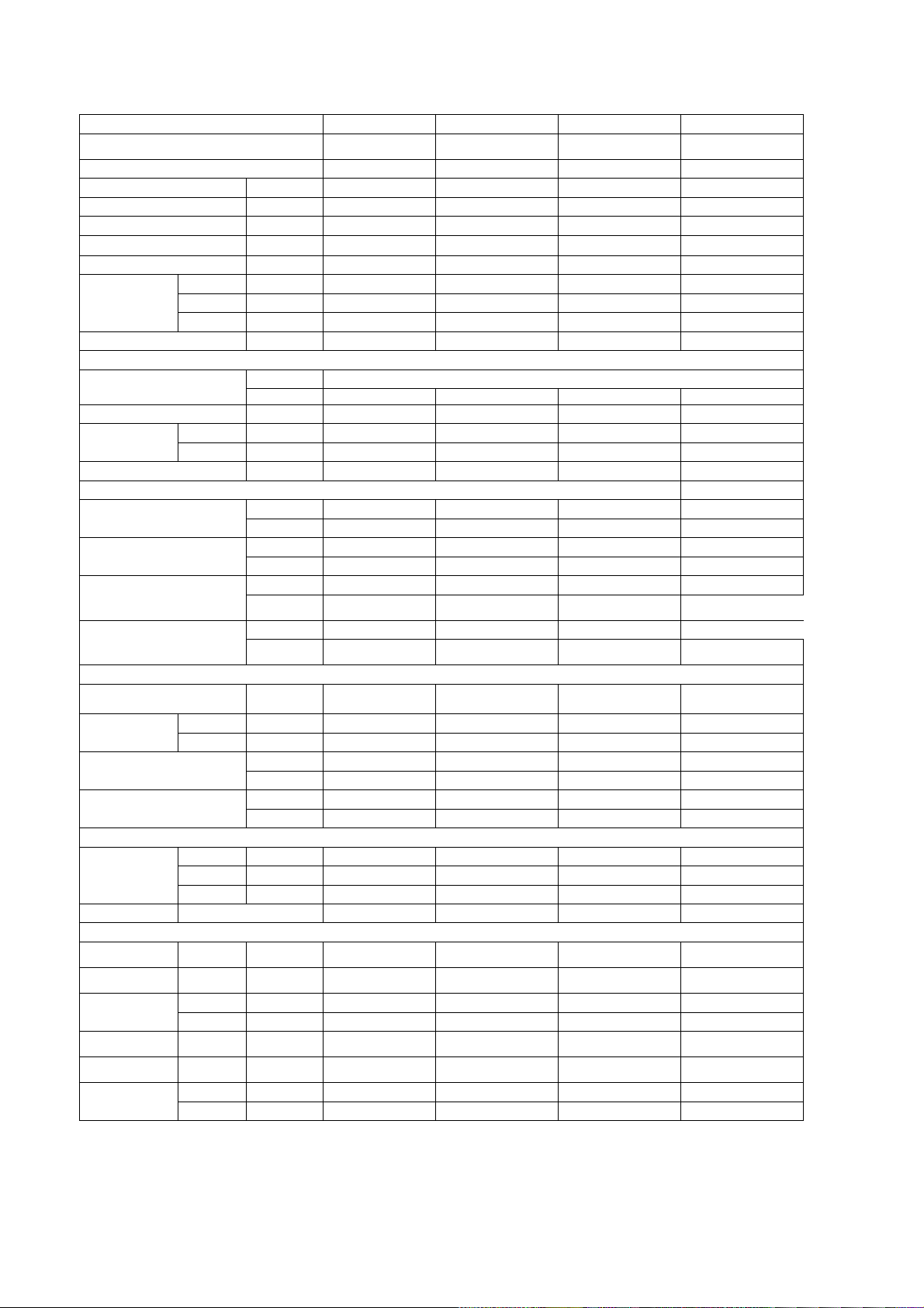
Unit dimensions
Unit dimensions
Packing dimensions
Packing dimensions
Technical Specifications
Model No.
Type
Control type
Rated cooling capacity
Rated heating capacity
EER for cooling
COP for heating
Moisture removal
Indoor noise level at
cooling
Outdoor noise level
Electrical Data
Power supply
[*Power cord w/o Top plug ]
Voltage Range
Rated Input Power
Annual energy consumption
Refrigerating System
Refrigerant
Compressor
Evaporator
Condenser
Fan System
Indoor air circulation(Cooling/Heating)
Indoor fan speed H/M/L
Indoor fan motor
Outdoor Fan Motor
Connections
Connecting Pipe
Connecting Wiring 1.0x3; 0.75x2 1.0x3; 0.75x2 1.5x3; 0.75x2 0.75x4; 0.75x2
Others
(W x H x D)
(W x D x H)
Net weight
(W x H x D)
(W x D x H)
Gross weight
High dB(A) 40 44 52 53
Med. dB(A) 36 40 48 48
Low dB(A) 32 36 44 44
Cooling W 860 1160 1710 2095
Heating W 890 1210 1760 2060
Cooling rpm 1270/1170/1000 1350/1250/1150 1350/1250/1150 1350/1130/980/830
Heating rpm 1250/1150/1050 1250/1150/1000 1250/1150/1000 1350/1130/980/830
Gas Inches
Liquid Inches
Length m 3 3 3 3
Size x Core number
Indoor mm 718×240×190 770x240x190 900x280x215 1033×313×220
Outdoor mm 700×256×552 700×256×552 820x605x300 902×315×650
Indoor kg 7 8 10 14
Outdoor kg 27 28 42 50
Indoor mm 805×305×260 860×305×260 985x365x300 1105×400×300
Outdoor mm 805×365×630 805×365×630 950x655x430 1015×435×740
Indoor kg 9 10 13 18
Outdoor kg 30 31 45 55
Btu/h;W 9000;2640 12000;3520 18000;5275 22000;6450
Btu/h;W 9500;2780 12500;3660 18500;5420 22500;6600
W/W 3.08 3.04 3.08 3.08
W/W 3.12 3.03 3.08 3.20
L/h 1.0 1.5 2.0 2.5
dB(A) 52 55 57 63
Rating
Type / Source Indoor Indoor Indoor Outdoor
V 198~264 198~264 198~264 198~264
kwh (cooling) 430 580 855 1048
Type R410A R410A R410A R410A
Amount (g) 670 850 1300 1570
Manufacturer RECHI GMCC GMCC GMCC
Model 44A203BJ&FJKC ASM140V1VDZ PA196G2C-4MUL PA250G2CS-4MUL
Fin Color Blue Blue Blue Blue
Specification
(Length, FPI)
Fin Color Blue Blue Blue Blue
Specification
(Length, FPI)
m3/h
Maker Welling Board-Ocean Tongde Electric Welling
Insulation Class E E E E
Maker Board-Ocean Welling Welling Board-Ocean
Insulation Class B B B B
CS/CU-YA9RKE-7 CS/CU-YA12RKE-7 CS/CU-YA18RKE-7 CS/CU-YA24RKE-7
Heating Pump
(Hot & Cold)
Remote control Remote control Remote control Remote control
544,17 604,17 705,18 797,17
717,17 717,17 780,17 879,17
520/500 550/550 800/820 1200/1200
3/8''(Φ9.52) 3/8''(Φ9.52) 1/2'' (Φ12.7) 5/8''(Φ15.88)
1/4''(Φ 6.35) 1/4''(Φ 6.35) 1/4''(Φ6 --> Φ 6.35) 1/4''(Φ 6.35)
Heating Pump
(Hot & Cold)
230V~/50Hz/1Φ
Heating Pump
(Hot & Cold)
Heating Pump
(Hot & Cold)
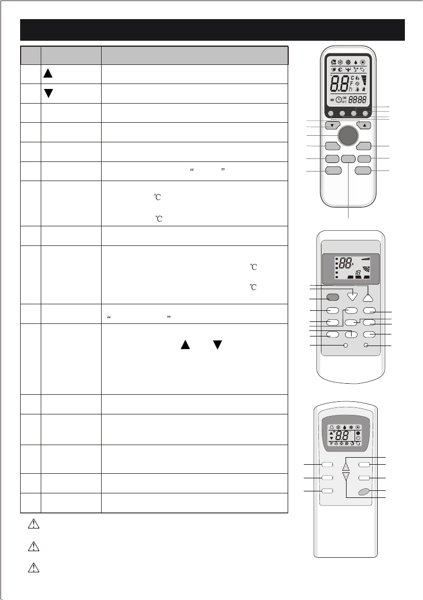
REMOTE CONTROL
No.
1
2
3
4
5
6
7
8
9
10
11
Button
(TEMP UP)
(TEMP DN)
ON/OFF
FAN
TIMER
SLEEP
ECO
MODE
SUPER
SWING
CLOCK
Function
Increase the temperature or time by 1 unit
Decrease the temperature or time by 1 unit
To switch the conditioner on and off.
To select the fan speed of auto/low/mid/high
To set automatic switching-on/off
To activate the function SLEEP
In cooling mode,press this button ,the temperature
will increase 2 on the base of setting temperature
In heating mode, press this button, the temperature
will decrease 2 on the base of setting temperature
To select the mode of operation
In cooling mode, press this button, the unit will give
the maximum cooling temperature with 16
In heating mode, press this button, the unit will give
the maximum heating temperature with 31
To activate or deactivate of the movement of the
DEFLECTORS .
When you press this button,the time will be flickering;then through" "and " ",you can adjust
the time(one time you press,one minute you adjust;and if you continue to press,the time change
rapidly ), after adjusting to your required time,
please press this button again to fix the time.
1
2
3
4
5
6
COOL
1
2
3
8
FAN SPEED SUPER ECO
4
5
6
10
12
DISPLAY HEALTHY3D
CLOCK
ON/OFF
FAN
TIMER
SLEEP MODE
SWING
ECO
SUPER
7
FEEL
AUTOQUIET
POWERFUL
C
DRY
FAN
HEAT
ON/OFF
MODE TIMER
SWING SLEEP HEALTHY
hr
DELAY
OFF
ON
HEALTHY
TIMER
ANTI-MILDEW
DISPLAY RESET
ON
FAN
SPEED
AIR
SWING
14
13
12
11
10
9
8
16
9
7
13
15
12
DISPLAY
To LED display (if present) switch on/off the
To switch - on /off HEALTHY funtion.It is a button
13
HEALTHY
which controls the ionizer or plasma generator only
for inverter type.
This button is useless for wall-mounted type.
14
15
16
RESET
ANTI-MILDEW
3D
When you press "3D", the horizontal and vertical
vanes will swing together at the same time.
To restart REMOTE CONTROL
To activate the function ANTI-MILDEW
The outlooking and some function of remote control may vary according
to the model.
The shape and position of buttons and indicators may vary according to
the model, but their function is the same.
The unit confirms the correct reception of each press button with a beep.
3
Dry
Heat
Fan
Feel Cool
Timer
C
OFF
Timer
h
Auto
SLEEP
6
TIMER
5
MODE
8
ON
Low
Mid
High
Sleep
Swing
1
FAN
4
SWING
10
3
ON/OFF
2
Air Conditioner Service Manual
Electronic controller:
1.Automatic mode
1) Initial RT determines the working mode and ST,the mode is determined effective only once unless
A/C shut-down then re-started. If from other modes switches to autoamatic mode (including mode
conversion after shutdown), it should be that the compress stop more than 3 min then temperature
judgement and automatic mode are conducted (it can conduct immediately from fan mode switched
to automatic, the indoor fan stops, three minutes later the response is made and start up). Within 3
min, the output as: Showing the room temperature, indoor fans starts (or anti-cold airflow), the
outdoor fan stops;
2) With memory controller, once being turned off or in case of an accidently power cut, the A/C is able
to retain and restore the original mode when being turned on or the power supply is resumed, if the
auto restart function activated. power-down after power-on; while if the auto restart fundction isn’t
activated, the A/C enters standby state.
Heat pump
Mode Initial RT Initial ST
Cooling
Dehumifying
Heating
RT≥26℃ 23℃
26℃>RT≥20℃ 18℃
RT<20℃ 23℃
Cooling-only
Mode Initial RT Initial ST
Cooling
Dehumifying
Ventilating
RT≥26℃ 23℃
26℃>RT≥20℃ 18℃
RT<20℃ -
Under automatic mode (including from automatic converted into dehumidifying Dry mode), when the
temperature up and down signals from the remote controller is received, the setting temperature ST
adjusts correspondingly to the current room temperature plus or minus 1℃, the automatic regulating
temperature range is ± 2℃.
2.Cooling mode
1) The control of the compressor
a. When RT-ST≥1℃,the compressor is running.
b. When RT-ST<-1℃,the compressor is off.
c. When -1℃≤RT-ST<1℃, the compressor keeps its original state.
2) Outdoor fan motor and the compressor run simultaneously (except for defrosting).
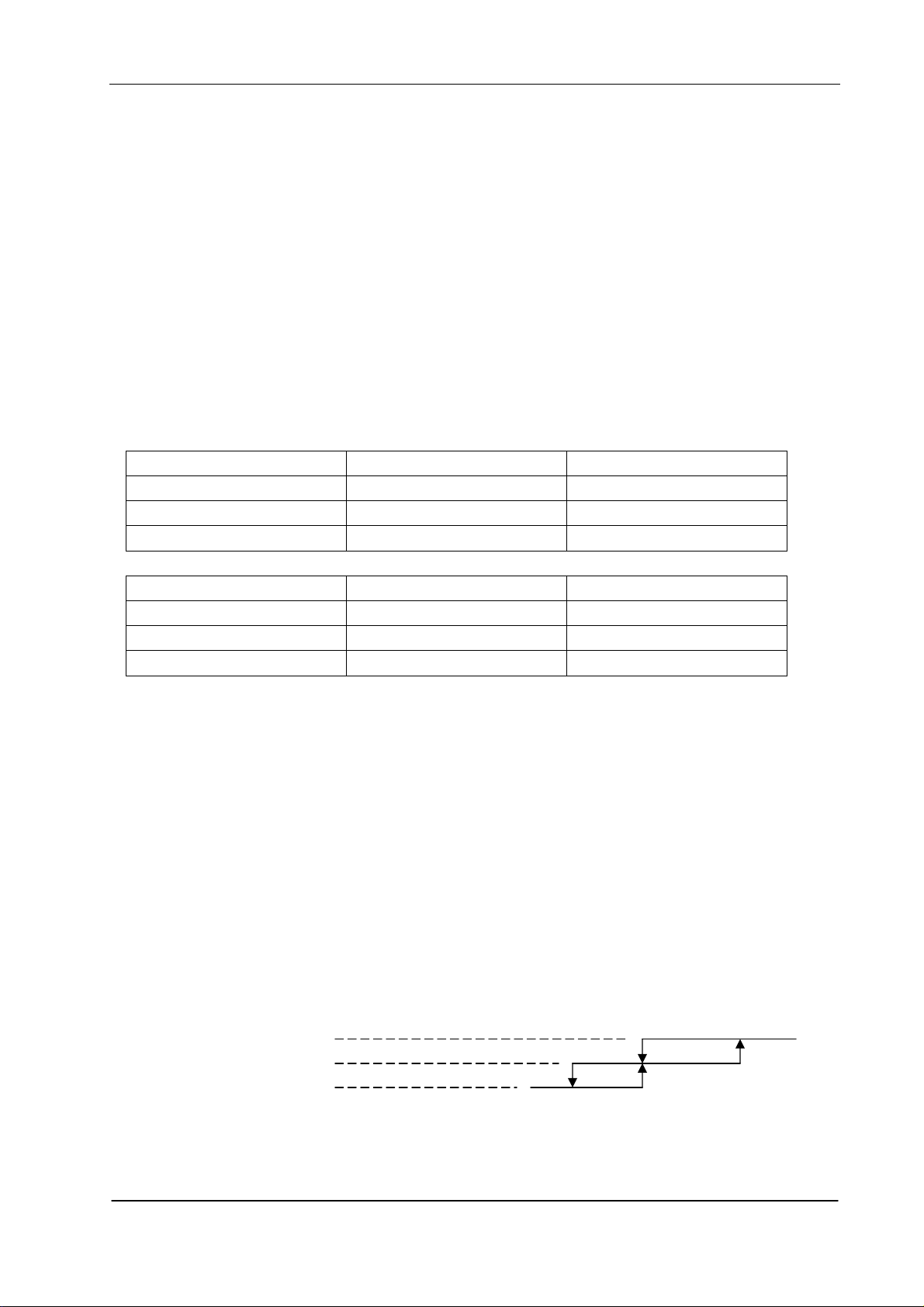
3) The control of indoor fan motor:
a. Indoor fan motor can operate by automatic, low, middle, and high airflow speed circularly.
b. Indoor fan motor’s the automatic airflow speed control Indoor fan motor can operate by automatic,
as shown in Figure 1:
Hi
Mid
Lo
RT-ST 1℃ 2℃ 4℃
Figure 1 Cooling automatic airflow
When the temperature changes lead to changes in airflow speed, the switch can only be made
orderly, and every grade of air flow speed runs 1 minute at least.
4
Air Conditioner Service Manual
3. Dry mode
running into this mode, the Air cond. firstly operates for 3 minutes according to cooling mode (set
temperature is 16℃ or 18℃) , and then takes the detected backflow air temperature minus 2℃ as a
new set temperature (the minimum value of 16℃) and runs according to cooling mode, indoor fan
operates at low-speed, at this moment the setting operation of Fan speed is invalid but Swing is
adjustable.
4. Heating mode
On the Heating mode, the room temperature is repaired. After repaired, the room temperature
display on the LED CRT=RT-3℃.
1) The control of the compressor
a. When ST-CRT≥1℃,the compressor is running.
b. When ST-CRT<-1℃,the compressor is off.
c. When -1℃≤ST-CRT<1℃, the compressor keeps its original state
2) Outdoor fan motor and the compressor run simultaneously (except for defrosting)
3) The control of indoor fan motor:
a. Indoor fan motor can operate by automatic, low, middle, and high airflow speed circularly.
b. indoor fan motor’s the automatic airflow speed control Indoor fan motor can operate by automatic,
as shown in Figure 2:
Hi
Mid
Lo
ST-CRT 1℃ 2℃ 4℃
Figure 2 Heating automatic airflow
When the temperature changes lead to changes in airflow speed, the switch can only be made
orderly, and every grade of air flow speed runs 1 minute at least.
4) Vane motor control: run as set state.
5) 4-way valve control:
a. Under heating mode, the four-way valve maintains well-connected status (including the
compressor stops on set condition, but except for the defrosting process)
b. When the mode switches into the heating mode or start-up, four-way valves will open 5 Seconds
before the compressor starts; while the mode exits from the heating mode or turn off, the four-way
valve will close 2min after after the shut-down the compressor.
6) Defrosting function:
During defrosting, once mode switch, temperature setting signals received, and the buzzer and
display make response immediately, but the other operations won’t implemented until defrosting
finished;
During defrosting, the signals of on-off, timing, sleep, airflow speed ans swing will be responded, but
the airflow speed and swing should be in accordance with anti-cold air rules.
Except the above signal processing during defrosting, no other signals will be dealt with, but only a
loud buzz.
During defrosting, electrical heating stops compulsively.
Defrosting enter and exit pragram:
Option 1:with jumper JC
5
Air Conditioner Service Manual
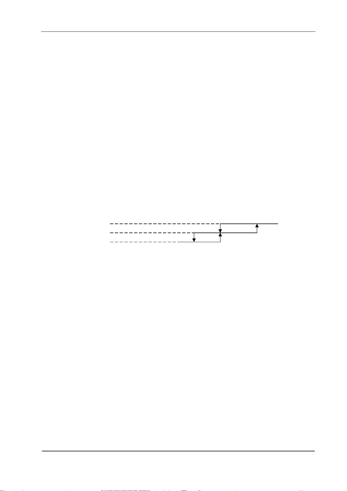
The condition of enter defrosting: run into defrosting once any of condition 1, 2, and 3 met.
Condition 1:As shown in figure 3
Defination:
The followings are all required to meet:
a. IPT1 settles for IPT1=IPTmax-△IPT(8℃)
b. t5≥50min(running time t5≥50min(the compressor runs cumulatively),t5 is removable,and could
be less than t1)
c. IPT<40℃,and lasts 2min。
Running into defrosting on condition 1, the first running time of set defrosting is F (8min); after running
a defrosting cycle, the defrosting time should be determined and adjusted.
Figure 3
Condition 2: When running time is more than or equal to 120 min (compressor is running
accumulatively), the indoor temperature is less than 35 ° C for 2 min sustained. Running into
defrosting under condition 2, defrosting time set is 8 min.
Condition 3: after the compressor is operating for 20min continuously, the indoor temperature is less
than 23 ° C which is anti-cold wind temperature when the fan stops running(including temperature
droping when compressor operating, not including the compressor’s starting course), and the
machine runs into defrosting according to any one condiciton as below) Running into defrosting under
condition 3, defrosting time set is 10 min.
a) Running into the first defrosting in 20 min after start-up.
b) The interval from last defrosting equivalent to or more than 50 min (stopping the compressor or the
machine in standby is allowed in the meantime).
Option 2: No Jumper JC, and no OPT outdoor sensor
when the compressor runs for 45 min, if the indoor coil temperature is less than 40 ° C for 2 min, the
machine runs into defrosting, and lasts for 3min, otherwise when the compressor runs for 120 min,
the machine runs into defrosting automatically and last for 10 min.
Option 3: No jumper JC, but with OPT outdoor sensor
When heating, when the temperature of outdoor unit under heat-exchange is lower than E ° C (-4 ° C),
and the compressor runs for 45 min, then the machine runs into defrosting and last for 10 min.
6
Air Conditioner Service Manual
Option 4. When heating, when the outdoor fan motor stopped but the compressor not stopped
accumulative total 30min, then the machine runs into defrosting and last for 8 min. if the accumulative
total less than 30min, but accord with one of the condition option 1-3 them the machine runs into
defrosting at the option 1-3 and the accumulative tota time restarts from 0.
Conditions for quitting defrostng
(1) The quitting conditions for option 1 and option 2, the machine quits from defrosting if any one
below condition met.
a. Defrosring time is over.
b.When it runs in defrosting for three minutes, the IPT indoor coil temperature rises 15 ° C or above
from the bottom point.
(2) The quitting conditions for option 3.
When OPT ≥ 20 ° C or defrosting for more than 10 min, then quit from defrosting.
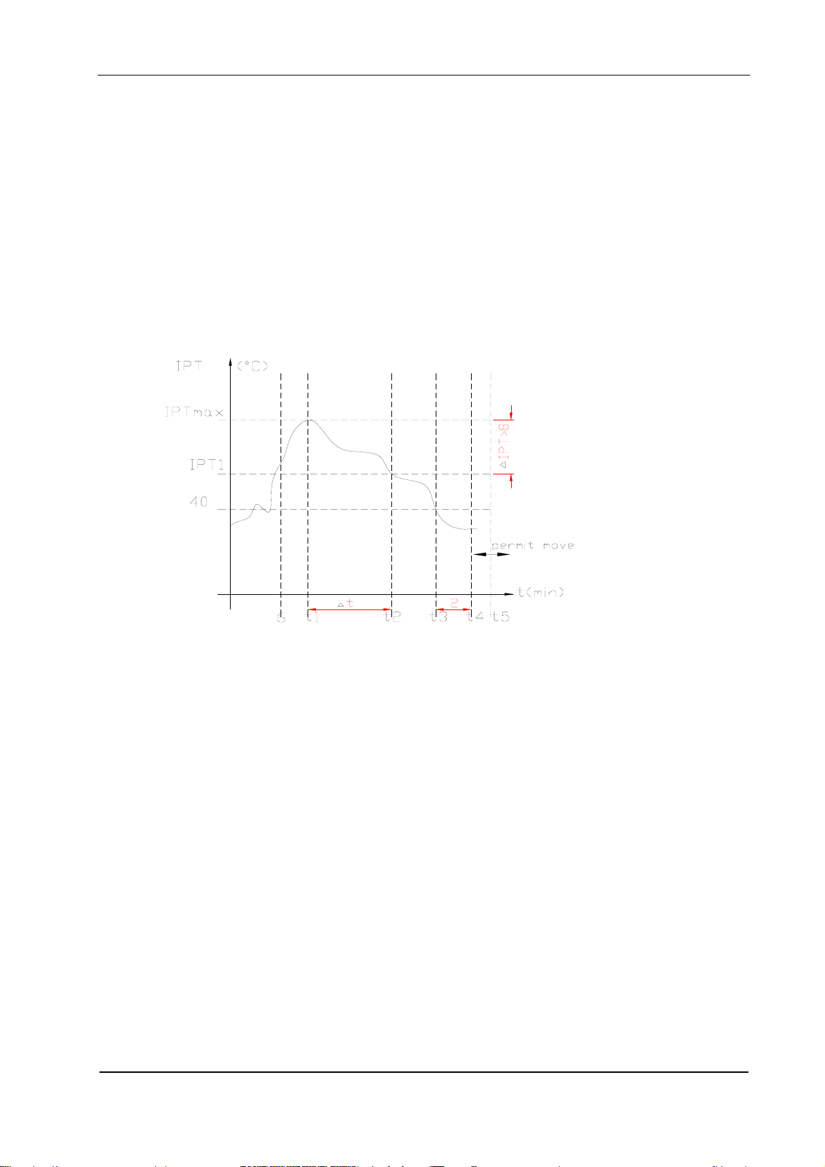
(3) Defrosting process shown in Figure 4
Figure 4 Defrosting process
7) Auxiliary Electric heating function
(1)The default condition is automatic on/off the electric heating function.
(2) The conditions of auxiliary electric heating(all the following conditions must be met)
a. the compressor runs for more than 3min;
b. indoor fan runs normally;
c. not in defrosting state;
d. auxiliary electric heating is turned off for more than 30s。
e. ST-RT≥3°C;
f. RT﹤22°C;
g. IPT≤43°C;
(3) The conditions of stopping auxiliary electric heating(any one of the following conditions met, the
state stops)
a. the compressor stops
b. RT≥24°C;
c. IPT≥48°C
d. indoor fan stops。
e. running into sleeping function
5. Fan mode
7
 Loading...