

Order No. MAC0801088C2
Air Conditioner
Indoor Unit Outdoor Unit
CS-CE7HKEW CU-CE7HKE
CS-CE9HKEW CU-CE9HKE
CS-CE12HKEW CU-CE12HKE
Please file and use this manual together with the service manual for Model No. CU-2E18CBPG, CU-3E23CBPG, CU-
4E27CBPG, Order No. RAC0209005C2, Model No. CU-3E18EBE, Order No. RAC0503011C2 and Model No. CU-2E15GBE,
Order No. MAC0704001A2.
TABLE OF CONTENTS
PAG E PAG E
1 Safety Precautions ----------------------------------------------- 2
2 Specifications ----------------------------------------------------- 4
2.1. CS-CE7HKEW CU-CE7HKE -------------------------- 4
2.2. CS-CE9HKEW CU-CE9HKE -------------------------- 6
2.3. CS-CE12HKEW CU-CE12HKE ----------------------- 8
2.4. Outdoor Unit: CU-2E15GBE ---------------------------10
2.5. Outdoor Unit: CU-3E18EBE ---------------------------11
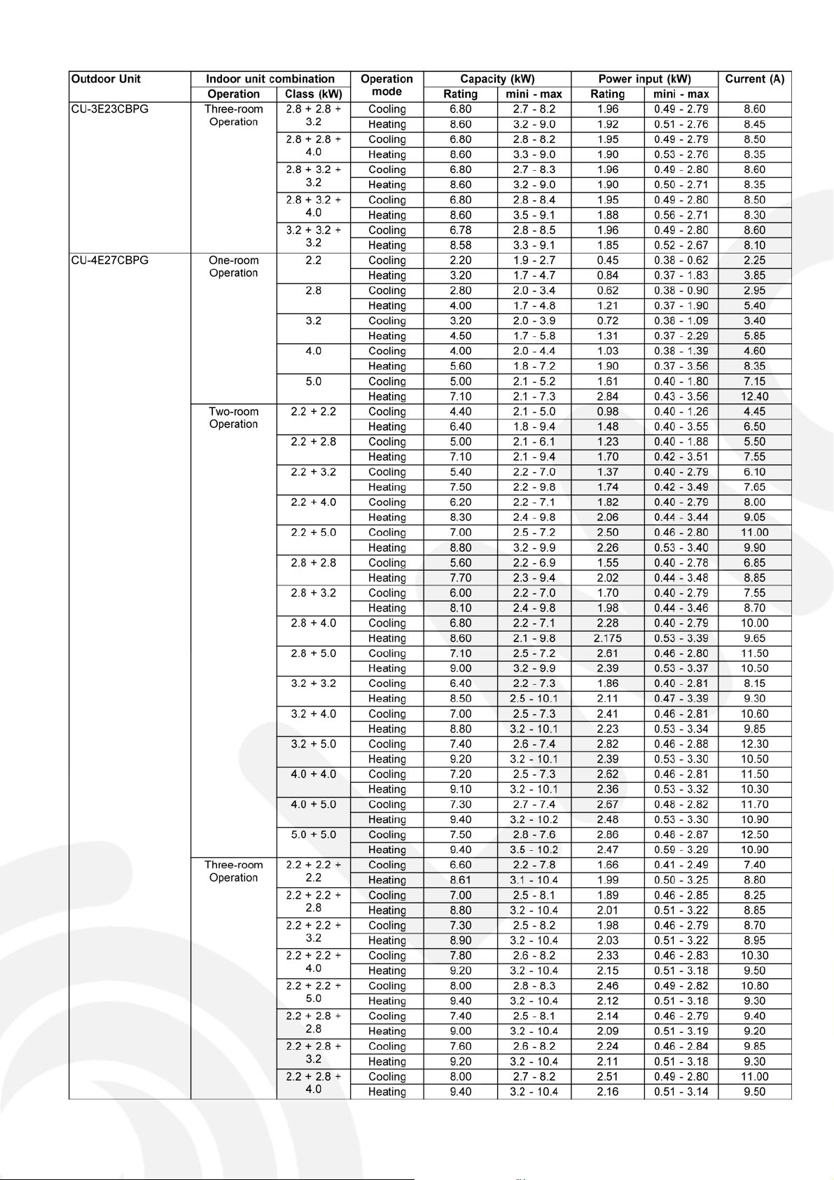
2.6. Outdoor Unit: CU-3E23CBPG CU-
4E27CBPG-------------------------------------------------12
3Features------------------------------------------------------------16
4 Location of Controls and Components ------------------18
4.1. Indoor Unit--------------------------------------------------18
4.2. Outdoor Unit ----------------------------------------------- 18
4.3. Remote Control------------------------------------------- 18
5Dimensions------------------------------------------------------- 19
5.1. Indoor Unit ------------------------------------------------- 19
5.2. Outdoor Unit ----------------------------------------------- 20
6 Refrigeration Cycle Diagram-------------------------------- 21
7 Block Diagram --------------------------------------------------- 22
8 Wiring Connection Diagram--------------------------------- 23
8.1. Indoor Unit ------------------------------------------------- 23
8.2. Outdoor Unit ----------------------------------------------- 24
9 Electronic Circuit Diagram----------------------------------- 25
9.1. Indoor Unit ------------------------------------------------- 25
© 2007 Panasonic HA Air-Conditioning (M) Sdn. Bhd.
(11969-T). All rights reserved. Unauthorized copying
and distribution is a violation of law.
9.2. Outdoor Unit ----------------------------------------------- 26
10 Printed Circuit Board ------------------------------------------27
10.1. Indoor Unit ------------------------------------------------- 27
10.2. Outdoor Unit ----------------------------------------------- 29
11 Installation Instruction ---------------------------------------- 30
11.1. Select The Best Location ------------------------------ 30
11.2. Indoor/Outdoor Unit Installation Diagram ----------30
11.3. Indoor Unit ------------------------------------------------- 31
11.4. Outdoor Unit----------------------------------------------- 34
12 Operation Control ----------------------------------------------- 37
12.1. Basic Function --------------------------------------------37
12.2. Indoor Fan Motor Operation --------------------------- 38
12.3. Outdoor Fan Motor Operation------------------------- 39
12.4. Airflow Direction ------------------------------------------ 39
12.5. Quiet operation (Cooling Mode/Cooling area
of Dry Mode)----------------------------------------------- 40
12.6. Quiet operation (Heating) ------------------------------ 40
12.7. Powerful Mode Operation ------------------------------ 41
12.8. Timer Control----------------------------------------------41
12.9. Auto Restart Control-------------------------------------41
12.10. Indication Panel------------------------------------------- 42
12.11. Patrol Operation ------------------------------------------ 42
12.12. e-ion Operation -------------------------------------------44
13 Protection Control ---------------------------------------------- 47
13.1. Protection Control For All Operations -------------- 47
13.2. Protection Control For Cooling & Soft Dry
Operation -------------------------------------------------- 49
13.3. Protection Control For Heating Operation --------- 50
14 Servicing Mode-------------------------------------------------- 51
14.1. Auto OFF/ON Button ----------------------------------- 51
14.2. Select Remote Control Transmission Code------- 51
14.3. Remote Control Button --------------------------------- 52
15 Troubleshooting Guide --------------------------------------- 53
15.1. Refrigeration Cycle System --------------------------- 53
15.2. Breakdown Self Diagnosis Function ---------------- 55
15.3. Error Codes Table --------------------------------------- 56
16 Disassembly and Assembly Instructions -------------- 57
16.1. Indoor Electronic Controllers, Cross Flow Fan
and Indoor Fan Motor Removal Procedures------ 57
16.2. Outdoor Electronic Controller Removal
Procedure-------------------------------------------------- 61
17 Technical Data --------------------------------------------------- 62
17.1. Operation Characteristics ----------------------------- 62
17.2. Sensible Capacity Chart ------------------------------- 74
18 Exploded View and Replacement Parts List----------- 75
18.1. Indoor Unit------------------------------------------------- 75
18.2. Outdoor Unit ---------------------------------------------- 77
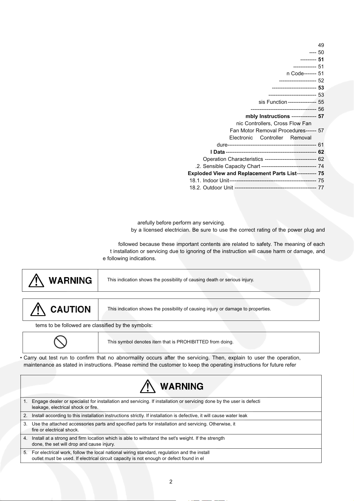
1 Safety Precautions
• Read the following “SAFETY PRECAUTIONS” carefully before perform any servicing.
• Electrical work must be installed or serviced by a licensed electrician. Be sure to use the correct rating of the power plug and
main circuit for the model installed.
• The caution items stated here must be followed because these important contents are related to safety. The meaning of each
indication used is as below. Incorrect installation or servicing due to ignoring of the instruction will cause harm or damage, and
the seriousness is classified by the following indications.
This indication shows the possibility of causing death or serious injury.
This indication shows the possibility of causing injury or damage to properties.
• The items to be followed are classified by the symbols:
This symbol denotes item that is PROHIBITTED from doing.
• Carry out test run to confirm that no abnormality occurs after the servicing. Then, explain to user the operation, care and
maintenance as stated in instructions. Please remind the customer to keep the operating instructions for future reference.
1. Engage dealer or specialist for installation and servicing. If installation or servicing done by the user is defective, it will cause water
leakage, electrical shock or fire.
2. Install according to this installation instructions strictly. If installation is defective, it will cause water leakage, electrical shock or fire.
3. Use the attached accessories parts and specified parts for installation and servicing. Otherwise, it will cause the set to fall, water leakage,
fire or electrical shock.
4. Install at a strong and firm location which is able to withstand the set's weight. If the strength is not enough or installation is not properly
done, the set will drop and cause injury.
5. For electrical work, follow the local national wiring standard, regulation and the installation instruction. An independent circuit and single
outlet must be used. If electrical circuit capacity is not enough or defect found in electrical work, it will cause electrical shock or fire.
2
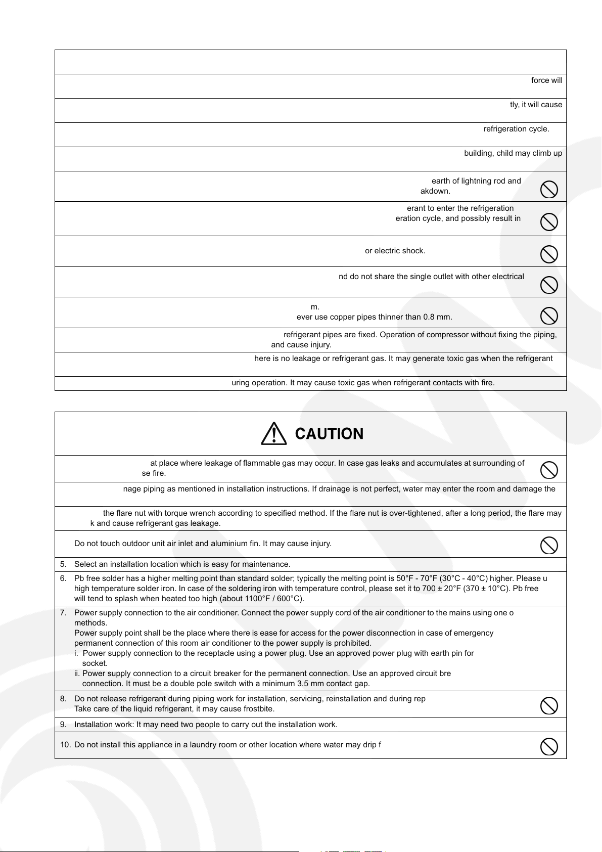
6. This equipment is strongly recommended to install with Earth Leakage Circuit Breaker (ELCB) or Residual Current Device (RCD).
Otherwise, it may cause electrical shock and fire in case equipment breakdown or insulation breakdown.
7. Use the specified cable and connect tightly for indoor/outdoor connection. Connect tightly and clamp the cable so that no external force will
be acted on the terminal. If connection or fixing is not perfect, it will cause heat-up or fire at the connection.
8. Wire routing must be properly arranged so that control board cover is fixed properly. If control board cover is not fixed perfectly, it will cause
heat-up or fire at connection point of terminal, fire or electrical shock.
9. When carrying out piping connection, take care not to let air substances other than the specified refrigerant go into refrigeration cycle.
Otherwise, it will cause lower capacity, abnormal high pressure in the refrigeration cycle, explosive and injury.
10. Do not install outdoor unit near handrail of veranda. When installing air-conditioner unit at veranda of high rise building, child may climb up
to outdoor unit and cross over the handrail and causing accident.
11. This equipment must be properly earthed. Earth line must not be connected to gas pipe, water pipe, earth of lightning rod and
telephone. Otherwise, it may cause electric shock in case equipment breakdown or insulation breakdown.
12. When connecting the piping, do not allow air or any substances other than the specified refrigerant to enter the refrigeration
cycle. Otherwise, this may lower the capacity, cause abnormally high pressure in the refrigeration cycle, and possibly result in
explosion and injury.
13. Do not damage or use unspecified power supply cord. Otherwise it will cause fire or electric shock.
14. Do not modify the length of the power supply cord or use extension cord, and do not share the single outlet with other electrical
appliances. Otherwise, it will cause fire or electric shock.
15. It is desirable that the amount of residual oil is less than 40 mg/10 m.
Thickness of copper pipes used must be more than 0.8 mm. Never use copper pipes thinner than 0.8 mm.
16. During installation, before run the compressor, confirm the refrigerant pipes are fixed. Operation of compressor without fixing the piping,
setting the valves at open condition, a burst may occur and cause injury.
17. After completion of installation or service, confirm there is no leakage or refrigerant gas. It may generate toxic gas when the refrigerant
contacts with fire.
18. Ventilate if there is refrigerant gas leakage during operation. It may cause toxic gas when refrigerant contacts with fire.
1. Do not install the unit at place where leakage of flammable gas may occur. In case gas leaks and accumulates at surrounding of
the unit, it may cause fire.
2. Carry out drainage piping as mentioned in installation instructions. If drainage is not perfect, water may enter the room and damage the
furniture.
3. Tighten the flare nut with torque wrench according to specified method. If the flare nut is over-tightened, after a long period, the flare may
break and cause refrigerant gas leakage.
4. Do not touch outdoor unit air inlet and aluminium fin. It may cause injury.
5. Select an installation location which is easy for maintenance.
6. Pb free solder has a higher melting point than standard solder; typically the melting point is 50°F - 70°F (30°C - 40°C) higher. Please use a
high temperature solder iron. In case of the soldering iron with temperature control, please set it to 700 ± 20°F (370 ± 10°C). Pb free solder
will tend to splash when heated too high (about 1100°F / 600°C).
7. Power supply connection to the air conditioner. Connect the power supply cord of the air conditioner to the mains using one of the following
methods.
Power supply point shall be the place where there is ease for access for the power disconnection in case of emergency. In some countries,
permanent connection of this room air conditioner to the power supply is prohibited.
i. Power supply connection to the receptacle using a power plug. Use an approved power plug with earth pin for the connection to the
socket.
ii. Power supply connection to a circuit breaker for the permanent connection. Use an approved circuit breaker for the permanent
connection. It must be a double pole switch with a minimum 3.5 mm contact gap.
8. Do not release refrigerant during piping work for installation, servicing, reinstallation and during repairing a refrigerant parts.
Take care of the liquid refrigerant, it may cause frostbite.
9. Installation work: It may need two people to carry out the installation work.
10. Do not install this appliance in a laundry room or other location where water may drip from the ceiling, etc.
3
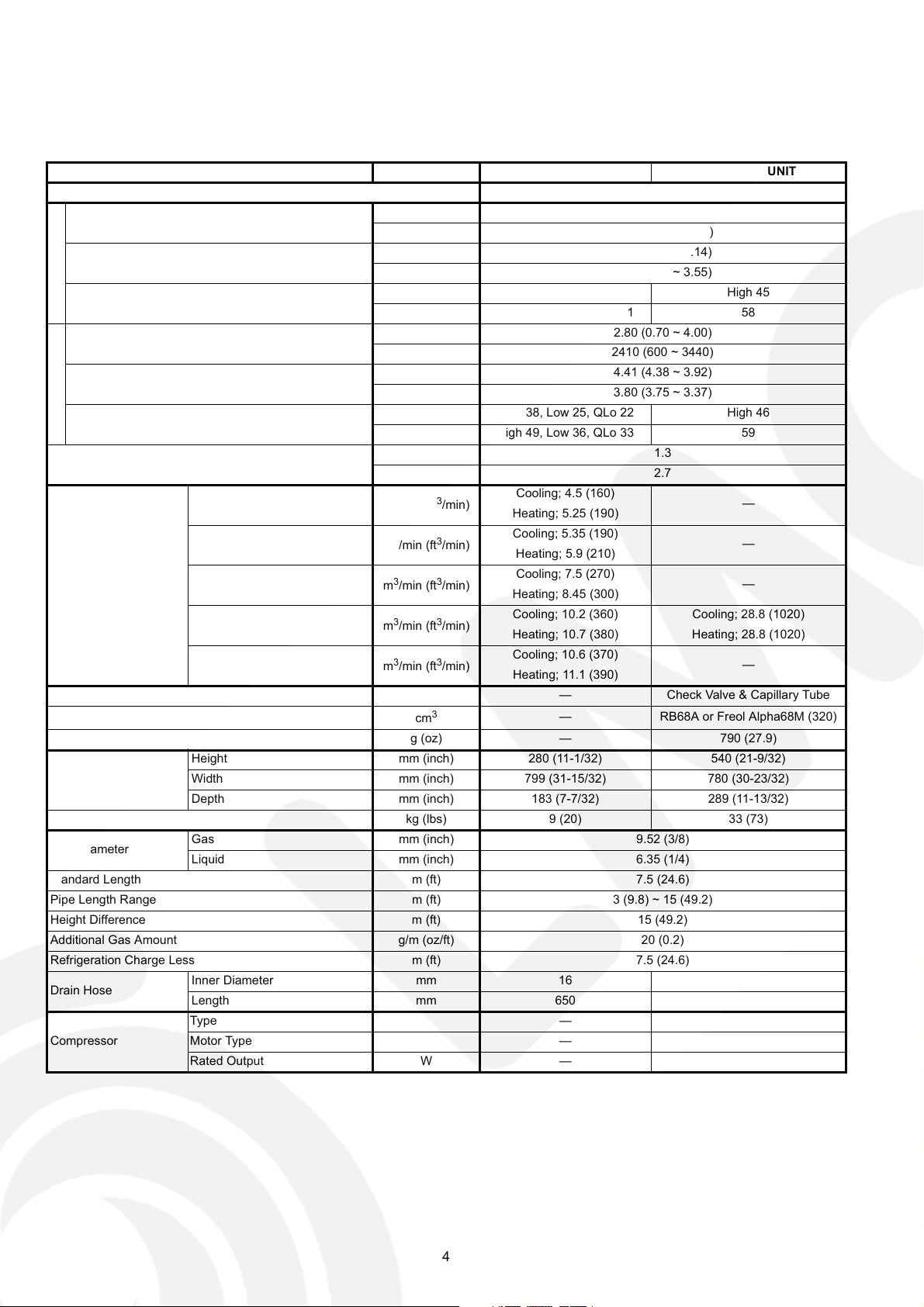
2 Specifications
2.1. CS-CE7HKEW CU-CE7HKE
ITEM UNIT INDOOR UNIT OUTDOOR UNIT
Performance Test Condition EUROVENT
C
Capacity
O
O
L
EER
I
N
Noise Level
G
H
Capacity
E
A
T
COP
I
N
Noise Level
G
Moisture Removal
QLo
Lo
Air Volume
Refrigeration Control Device — Check Valve & Capillary Tube
Refrigeration Oil
Refrigerant (R410A) g (oz) — 790 (27.9)
Dimension
Net Weight kg (lbs) 9 (20) 33 (73)
Pipe Diameter
Standard Length m (ft) 7.5 (24.6)
Pipe Length Range m (ft) 3 (9.8) ~ 15 (49.2)
Height Difference m (ft) 15 (49.2)
Additional Gas Amount g/m (oz/ft) 20 (0.2)
Refrigeration Charge Less m (ft) 7.5 (24.6)
Drain Hose
Compressor
Me
Hi
SHi
Height mm (inch) 280 (11-1/32) 540 (21-9/32)
Width mm (inch) 799 (31-15/32) 780 (30-23/32)
Depth mm (inch) 183 (7-7/32) 289 (11-13/32)
Gas mm (inch) 9.52 (3/8)
Liquid mm (inch) 6.35 (1/4)
Inner Diameter mm 16 —
Length mm 650 —
Type — Hermetic Motor
Motor Type — Brushless (6-pole)
Rated Output W — 650
kW 2.05 (0.70 ~ 2.40)
kCal/h 1760 (600 ~ 2060)
W/W 4.36 (4.12 ~ 4.14)
kCal/hW 3.74 (3.53 ~ 3.55)
dB (A) High 37, Low 24, QLo 20 High 45
Power level dB High 48, Low 35, QLo 31 58
kW 2.80 (0.70 ~ 4.00)
kCal/h 2410 (600 ~ 3440)
W/W 4.41 (4.38 ~ 3.92)
kCal/hW 3.80 (3.75 ~ 3.37)
dB (A) High 38, Low 25, QLo 22 High 46
Power level dB High 49, Low 36, QLo 33 59
l/h 1.3
pt/h 2.7
3
/min (ft3/min)
m
3
m
/min (ft3/min)
3
/min (ft3/min)
m
3
/min (ft3/min)
m
3
/min (ft3/min)
m
cm
3
Cooling; 4.5 (160)
Heating; 5.25 (190)
Cooling; 5.35 (190)
Heating; 5.9 (210)
Cooling; 7.5 (270)
Heating; 8.45 (300)
Cooling; 10.2 (360) Cooling; 28.8 (1020)
Heating; 10.7 (380) Heating; 28.8 (1020)
Cooling; 10.6 (370)
Heating; 11.1 (390)
— RB68A or Freol Alpha68M (320)
—
—
—
—
4
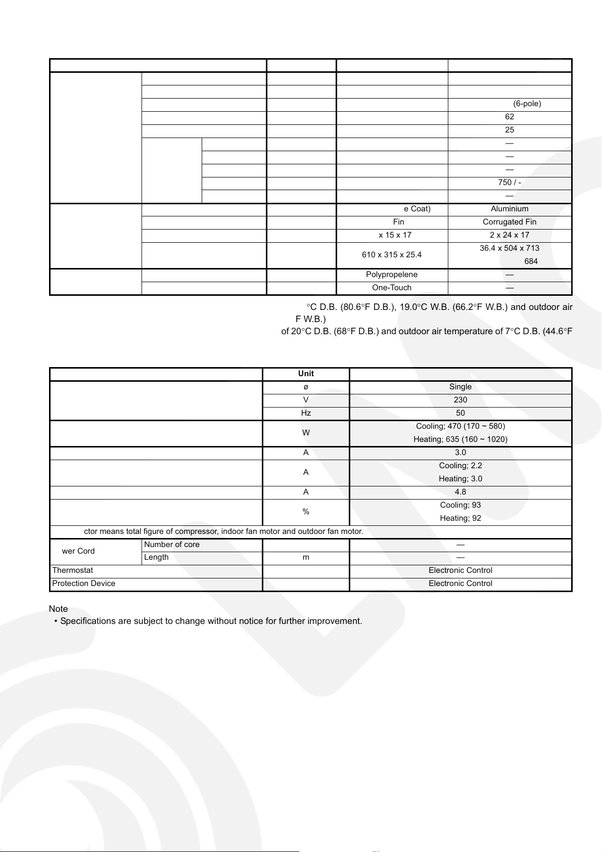
ITEM UNIT INDOOR UNIT OUTDOOR UNIT
Type Cross-Flow Fan Propeller Fan
Material ASG20K1 PP
Motor Type Transistor (8-pole) Induction (6-pole)
Input Power W — 62
Fan
Heat Exchanger
Air Filter
Output Power W 30 25
QLo (Cool/Heat) rpm 680 / 780 —
Lo (Cool/Heat) rpm 780 / 850 —
Fan Speed
Fin Material Aluminium (Pre Coat) Aluminium
Fin Type Slit Fin Corrugated Fin
Row x Stage x FPI 2 x 15 x 17 2 x 24 x 17
Size (W x H x L) mm 610 x 315 x 25.4
Material Polypropelene —
Type One-Touch —
Me (Cool/Heat) rpm 1010 / 1085 —
Hi (Cool/Heat) rpm 1240 / 1320 750 / -
SHi (Cool/Heat) rpm 1310 /1390 —
36.4 x 504 x 713
684
1. Cooling capacities are based on indoor temperature of 27qC D.B. (80.6qF D.B.), 19.0qC W.B. (66.2qF W.B.) and outdoor air
temperature of 35qC D.B. (95qF D.B.), 24qC W.B. (75.2qF W.B.)
2. Heating capacities are based on indoor temperature of 20qC D.B. (68qF D.B.) and outdoor air temperature of 7qC D.B. (44.6qF
D.B.), 6qC W.B. (42.8qF W.B.)
Item Unit
ø Single
Power Source (Phase, Voltage, Cycle)
Input Power W
Starting Current A 3.0
Running Current A
Maximum current A 4.8
Power Factor %
Power factor means total figure of compressor, indoor fan motor and outdoor fan motor.
Power Cord
Thermostat Electronic Control
Protection Device Electronic Control
Number of core —
Length m —
V 230
Hz 50
Cooling; 470 (170 ~ 580)
Heating; 635 (160 ~ 1020)
Cooling; 2.2
Heating; 3.0
Cooling; 93
Heating; 92
Note
• Specifications are subject to change without notice for further improvement.
5
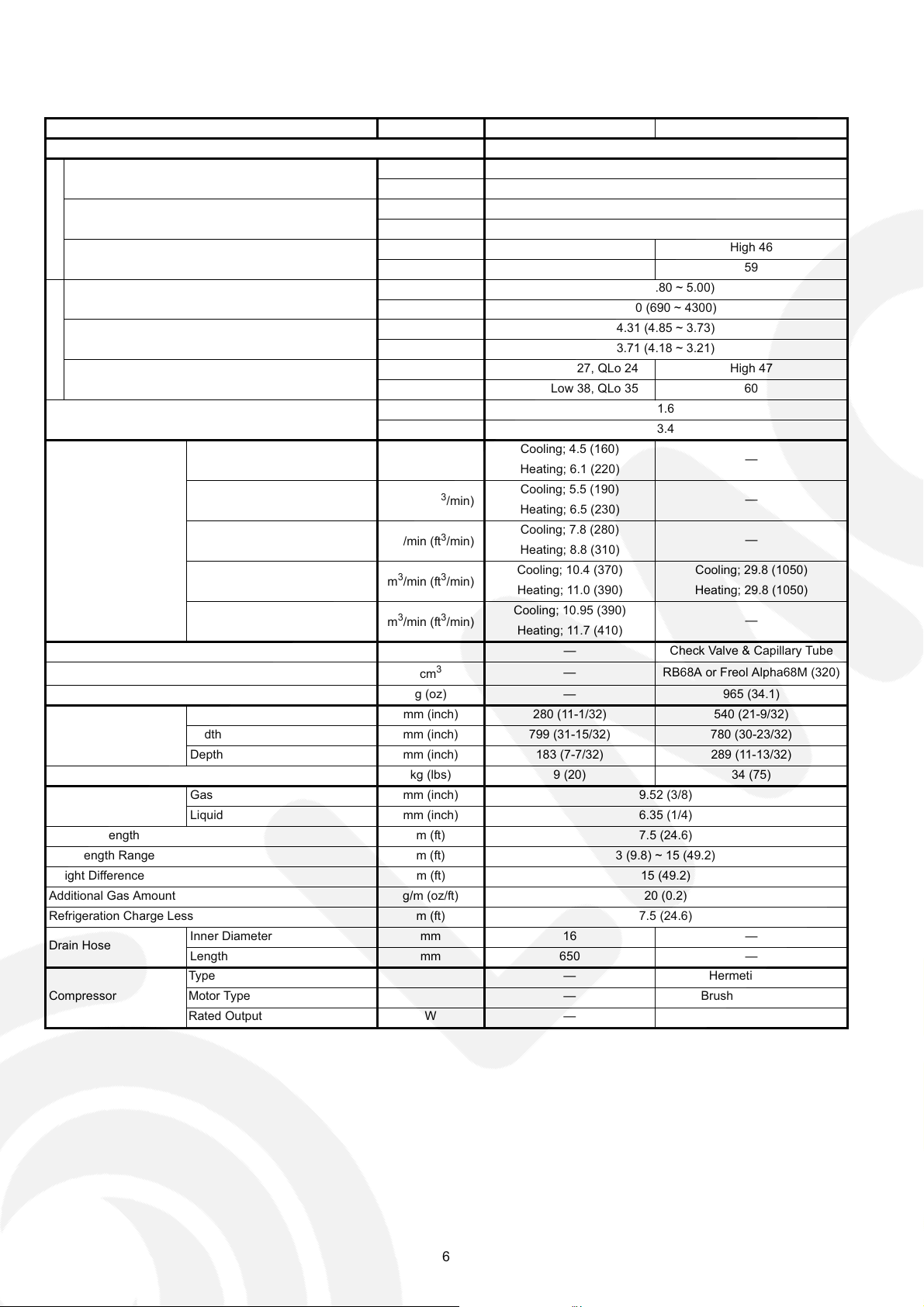
2.2. CS-CE9HKEW CU-CE9HKE
ITEM UNIT INDOOR UNIT OUTDOOR UNIT
Performance Test Condition EUROVENT
C
Capacity
O
O
L
EER
I
N
Noise Level
G
H
Capacity
E
A
T
COP
I
N
Noise Level
G
Moisture Removal
QLo
Lo
Air Volume
Me
Hi
SHi
Refrigeration Control Device — Check Valve & Capillary Tube
Refrigeration Oil
Refrigerant (R410A) g (oz) — 965 (34.1)
Height mm (inch) 280 (11-1/32) 540 (21-9/32)
Dimension
Width mm (inch) 799 (31-15/32) 780 (30-23/32)
Depth mm (inch) 183 (7-7/32) 289 (11-13/32)
Net Weight kg (lbs) 9 (20) 34 (75)
Pipe Diameter
Gas mm (inch) 9.52 (3/8)
Liquid mm (inch) 6.35 (1/4)
Standard Length m (ft) 7.5 (24.6)
Pipe Length Range m (ft) 3 (9.8) ~ 15 (49.2)
Height Difference m (ft) 15 (49.2)
Additional Gas Amount g/m (oz/ft) 20 (0.2)
Refrigeration Charge Less m (ft) 7.5 (24.6)
Drain Hose
Inner Diameter mm 16 —
Length mm 650 —
Type — Hermetic Motor
Compressor
Motor Type — Brushless (6-pole)
Rated Output W — 700
kW 2.60 (0.80 ~ 3.00)
kCal/h 2240 (690 ~ 2580)
W/W 4.41 (4.57 ~ 4.00)
kCal/hW 3.80 (3.94 ~ 3.44)
dB (A) High 39, Low 25, QLo 20 High 46
Power level dB High 50, Low 36, QLo 31 59
kW 3.60 (0.80 ~ 5.00)
kCal/h 3100 (690 ~ 4300)
W/W 4.31 (4.85 ~ 3.73)
kCal/hW 3.71 (4.18 ~ 3.21)
dB (A) High 40, Low 27, QLo 24 High 47
Power level dB High 51, Low 38, QLo 35 60
l/h 1.6
pt/h 3.4
3
/min (ft3/min)
m
3
m
/min (ft3/min)
3
/min (ft3/min)
m
3
m
/min (ft3/min)
3
/min (ft3/min)
m
cm
3
Cooling; 4.5 (160)
Heating; 6.1 (220)
Cooling; 5.5 (190)
Heating; 6.5 (230)
Cooling; 7.8 (280)
Heating; 8.8 (310)
Cooling; 10.4 (370) Cooling; 29.8 (1050)
Heating; 11.0 (390) Heating; 29.8 (1050)
Cooling; 10.95 (390)
Heating; 11.7 (410)
— RB68A or Freol Alpha68M (320)
—
—
—
—
6
ITEM UNIT INDOOR UNIT OUTDOOR UNIT
Type Cross-Flow Fan Propeller Fan
Material ASG20K1 PP
Motor Type Transistor (8-pole) Induction (6-pole)
Input Power W — 65
Fan
Heat Exchanger
Air Filter
Output Power W 30 25
QLo (Cool/Heat) rpm 720 / 890 —
Lo (Cool/Heat) rpm 830 / 940 —
Fan Speed
Fin Material Aluminium (Pre Coat) Aluminium
Fin Type Slit Fin Corrugated Fin
Row x Stage x FPI 2 x 15 x 19 2 x 24 x 17
Size (W x H x L) mm 610 x 315 x 25.4
Material Polypropelene —
Type One-Touch —
Me (Cool/Heat) rpm 1070 / 1170 —
Hi (Cool/Heat) rpm 1310 / 1400 770 / -
SHi (Cool/Heat) rpm 1390 / 1490 —
36.4 x 504 x 713
684
1. Cooling capacities are based on indoor temperature of 27qC D.B. (80.6qF D.B.), 19.0qC W.B. (66.2qF W.B.) and outdoor air
temperature of 35qC D.B. (95qF D.B.), 24qC W.B. (75.2qF W.B.)
2. Heating capacities are based on indoor temperature of 20qC D.B. (68qF D.B.) and outdoor air temperature of 7qC D.B. (44.6qF
D.B.), 6qC W.B. (42.8qF W.B.)
Item Unit
ø Single
Power Source (Phase, Voltage, Cycle)
Input Power W
Starting Current A 3.9
Running Current A
Maximum current A 5.9
Power Factor %
Power factor means total figure of compressor, indoor fan motor and outdoor fan motor.
Power Cord
Thermostat Electronic Control
Protection Device Electronic Control
Number of core —
Length m —
V 230
Hz 50
Cooling; 590 (175 ~ 750)
Heating; 835 (165 ~ 1340)
Cooling; 2.8
Heating; 3.9
Cooling; 92
Heating; 93
Note
• Specifications are subject to change without notice for further improvement.
7

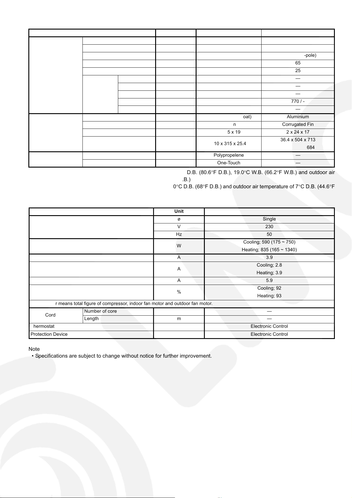
2.3. CS-CE12HKEW CU-CE12HKE
ITEM UNIT INDOOR UNIT OUTDOOR UNIT
Performance Test Condition EUROVENT
C
Capacity
O
O
L
EER
I
N
Noise Level
G
H
Capacity
E
A
T
COP
I
N
Noise Level
G
Moisture Removal
QLo
Lo
Air Volume
Me
Hi
SHi
Refrigeration Control Device — Check Valve & Capillary Tube
Refrigeration Oil
Refrigerant (R410A) g (oz) — 980 (34.6)
Height mm (inch) 280 (11-1/32) 540 (21-9/32)
Dimension
Width mm (inch) 799 (31-15/32) 780 (30-23/32)
Depth mm (inch) 183 (7-7/32) 289 (11-13/32)
Net Weight kg (lbs) 9 (20) 34 (75)
Pipe Diameter
Gas mm (inch) 9.52 (3/8)
Liquid mm (inch) 6.35 (1/4)
Standard Length m (ft) 7.5 (24.6)
Pipe Length Range m (ft) 3 (9.8) ~ 15 (49.2)
Height Difference m (ft) 15 (49.2)
Additional Gas Amount g/m (oz/ft) 20 (0.2)
Refrigeration Charge Less m (ft) 7.5 (24.6)
Drain Hose
Inner Diameter mm 16 —
Length mm 650 —
Type — Hermetic Motor
Compressor
Motor Type — Brushless (6-pole)
Rated Output W — 700
kW 3.50 (0.80 ~ 4.00)
kCal/h 3010 (690 ~ 3440)
W/W 3.83 (4.32 ~ 3.39)
kCal/hW 3.29 (3.73 ~ 2.92)
dB (A) High 42, Low 28, QLo 20 High 48
Power level dB High 53, Low 39, QLo 31 61
kW 4.80 (0.80 ~ 6.50)
kCal/h 4130 (690 ~ 5590)
W/W 3.81 (4.57 ~ 3.44)
kCal/hW 3.28 (3.94 ~ 2.96)
dB (A) High 42, Low 33, QLo 30 High 50
Power level dB High 53, Low 44, QLo 41 63
l/h 2.0
pt/h 4.2
3
/min (ft3/min)
m
3
m
/min (ft3/min)
3
/min (ft3/min)
m
3
m
/min (ft3/min)
3
/min (ft3/min)
m
cm
3
Cooling; 4.6 (160)
Heating; 8.0 (280)
Cooling; 6.4 (230)
Heating; 8.5 (300)
Cooling; 8.75 (310)
Heating; 10.2 (360)
Cooling; 11.2 (400) Cooling; 31.0 (1090)
Heating; 11.7 (410) Heating; 31.0 (1090)
Cooling; 11.7 (410)
Heating; 12.1 (430)
— RB68A or Freol Alpha68M (320)
—
—
—
—
8
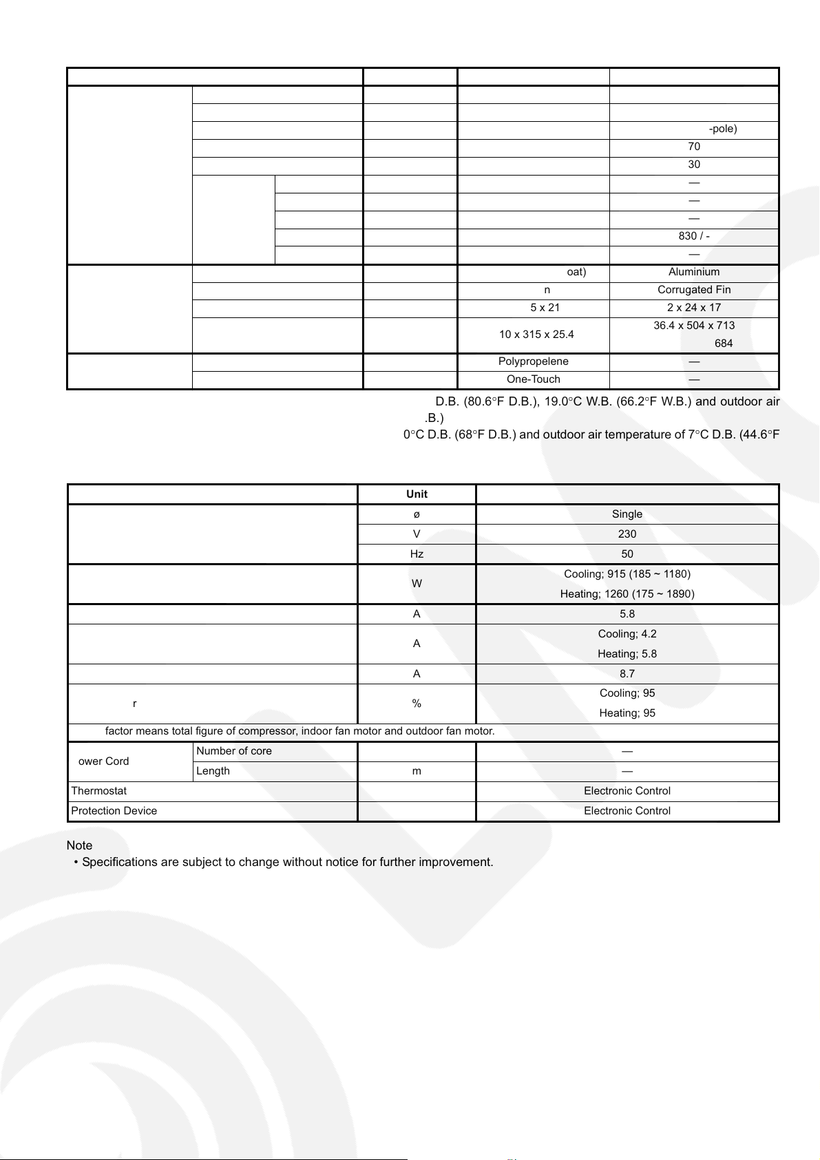
ITEM UNIT INDOOR UNIT OUTDOOR UNIT
Type Cross-Flow Fan Propeller Fan
Material ASG20K1 PP
Motor Type Transistor (8-pole) Induction (6-pole)
Input Power W — 70
Fan
Heat Exchanger
Air Filter
Output Power W 30 30
QLo (Cool/Heat) rpm 730 / 1090 —
Lo (Cool/Heat) rpm 920 / 1150 —
Fan Speed
Fin Material Aluminium (Pre Coat) Aluminium
Fin Type Slit Fin Corrugated Fin
Row x Stage x FPI 2 x 15 x 21 2 x 24 x 17
Size (W x H x L) mm 610 x 315 x 25.4
Material Polypropelene —
Type One-Touch —
Me (Cool/Heat) rpm 1175 / 1325 —
Hi (Cool/Heat) rpm 1430 / 1500 830 / -
SHi (Cool/Heat) rpm 1500 / 1550 —
36.4 x 504 x 713
684
1. Cooling capacities are based on indoor temperature of 27qC D.B. (80.6qF D.B.), 19.0qC W.B. (66.2qF W.B.) and outdoor air
temperature of 35qC D.B. (95qF D.B.), 24qC W.B. (75.2qF W.B.)
2. Heating capacities are based on indoor temperature of 20qC D.B. (68qF D.B.) and outdoor air temperature of 7qC D.B. (44.6qF
D.B.), 6qC W.B. (42.8qF W.B.)
Item Unit
ø Single
Power Source (Phase, Voltage, Cycle)
Input Power W
Starting Current A 5.8
Running Current A
Maximum current A 8.7
Power Factor %
Power factor means total figure of compressor, indoor fan motor and outdoor fan motor.
Power Cord
Thermostat Electronic Control
Protection Device Electronic Control
Number of core —
Length m —
V 230
Hz 50
Cooling; 915 (185 ~ 1180)
Heating; 1260 (175 ~ 1890)
Cooling; 4.2
Heating; 5.8
Cooling; 95
Heating; 95
Note
• Specifications are subject to change without notice for further improvement.
9
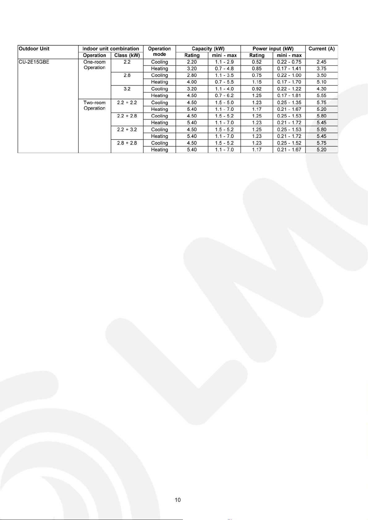
2.4. Outdoor Unit: CU-2E15GBE
10
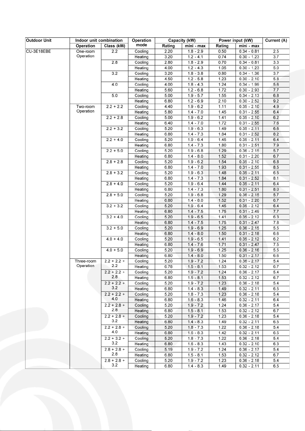
2.5. Outdoor Unit: CU-3E18EBE
11
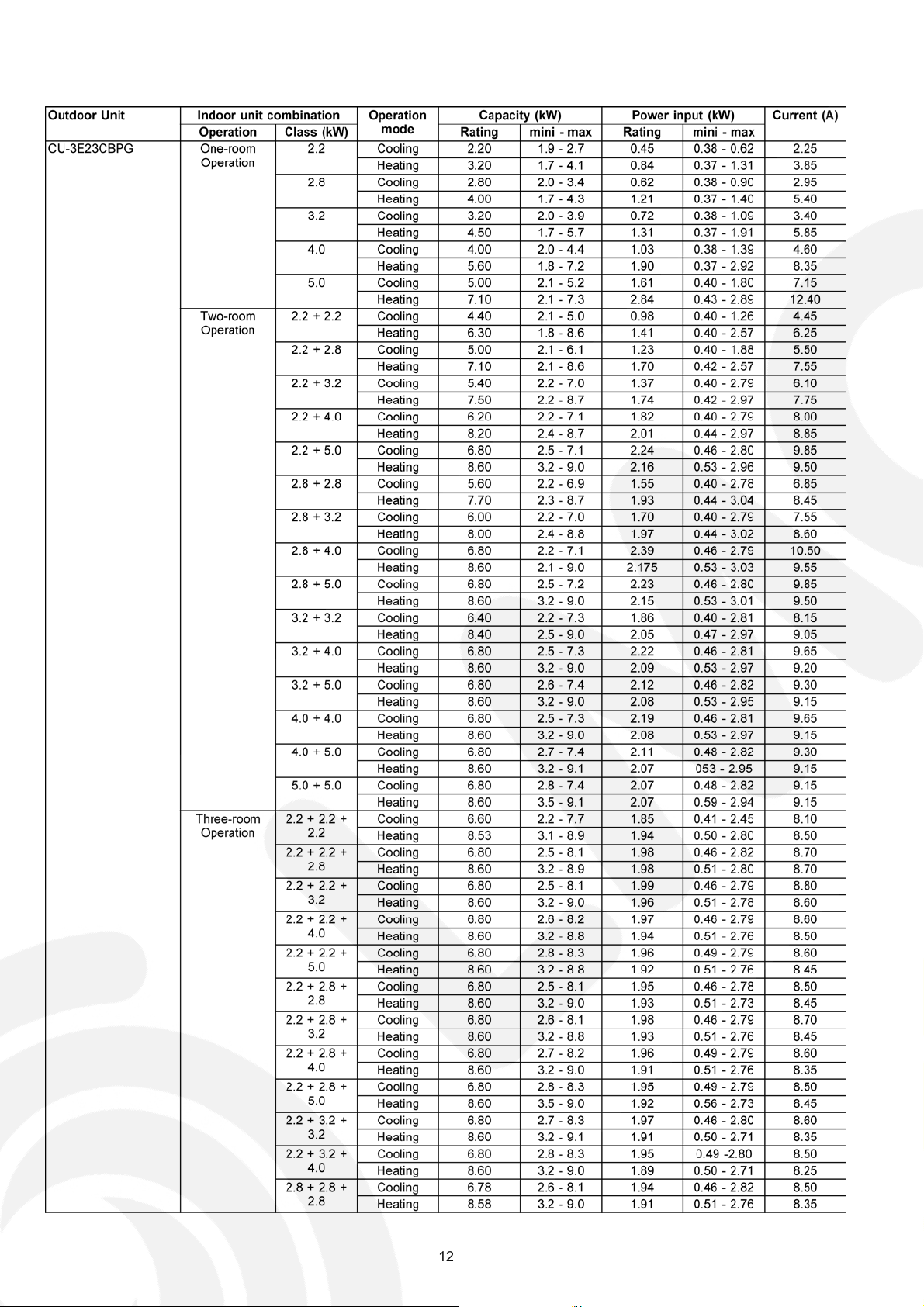
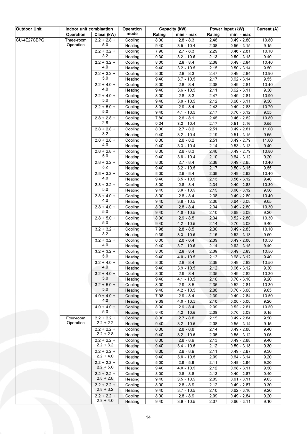
2.6. Outdoor Unit: CU-3E23CBPG CU-4E27CBPG
12
131415

3Features
• Inverter Technology
- Wider output power range
- Energy saving
- Quick Cooling
-Quick Heating
- More precise temperature control
• E-ion Air Purifying System with Patrol Sensor
- Active e-ions are released to catch dust particles and bring them back the large positively charged filter
• Environment Protection
- Non-ozone depletion substances refrigerant (R410A)
• Long Installation Piping
- CS/CU-CE7/9/12HK, long piping up to 15 meters
• Easy to use remote control
• Quality Improvement
- Random auto restart after power failure for safety restart operation
- Gas leakage protection
- Prevent compressor reverse cycle
- Inner protector to protect Compressor
- Noise prevention during soft dry operation
• Operation Improvement
- Quiet mode to reduce the indoor unit operating sound
- Powerful mode to reach the desired room temperature quickly
- 24-hour timer setting
• Serviceability Improvement
- Breakdown Self Diagnosis function
16
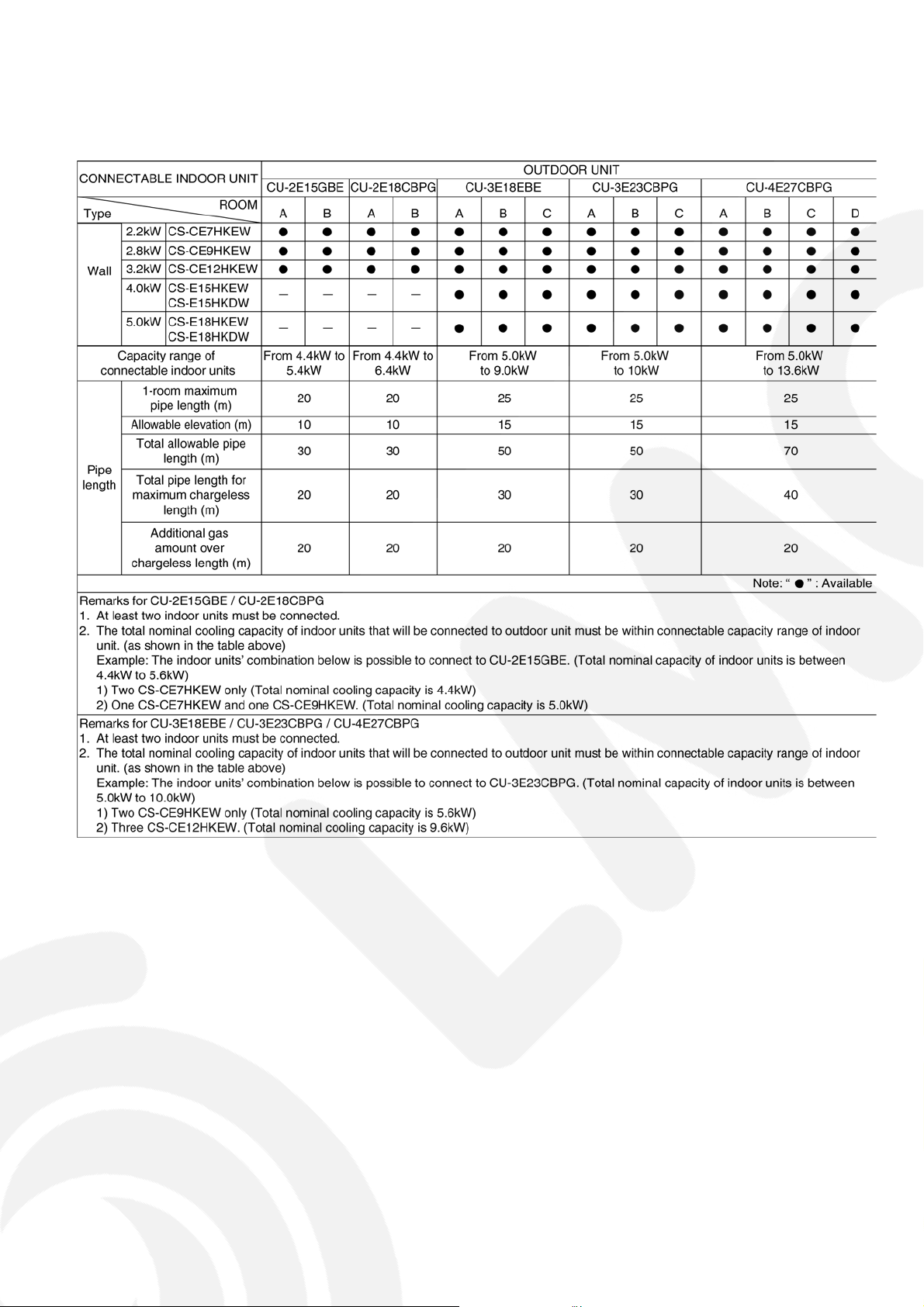
• Multi Split Combination Possibility:
- A single outdoor unit enables air conditioning of up to two separate rooms for CU-2E15GBE, CU-2E18CBPG.
- A single outdoor unit enables air conditioning of up to three separate rooms for CU-3E18EBE, CU-3E23CBPG.
- A single outdoor unit enables air conditioning of up to four separate rooms for CU-4E27CBPG.
17
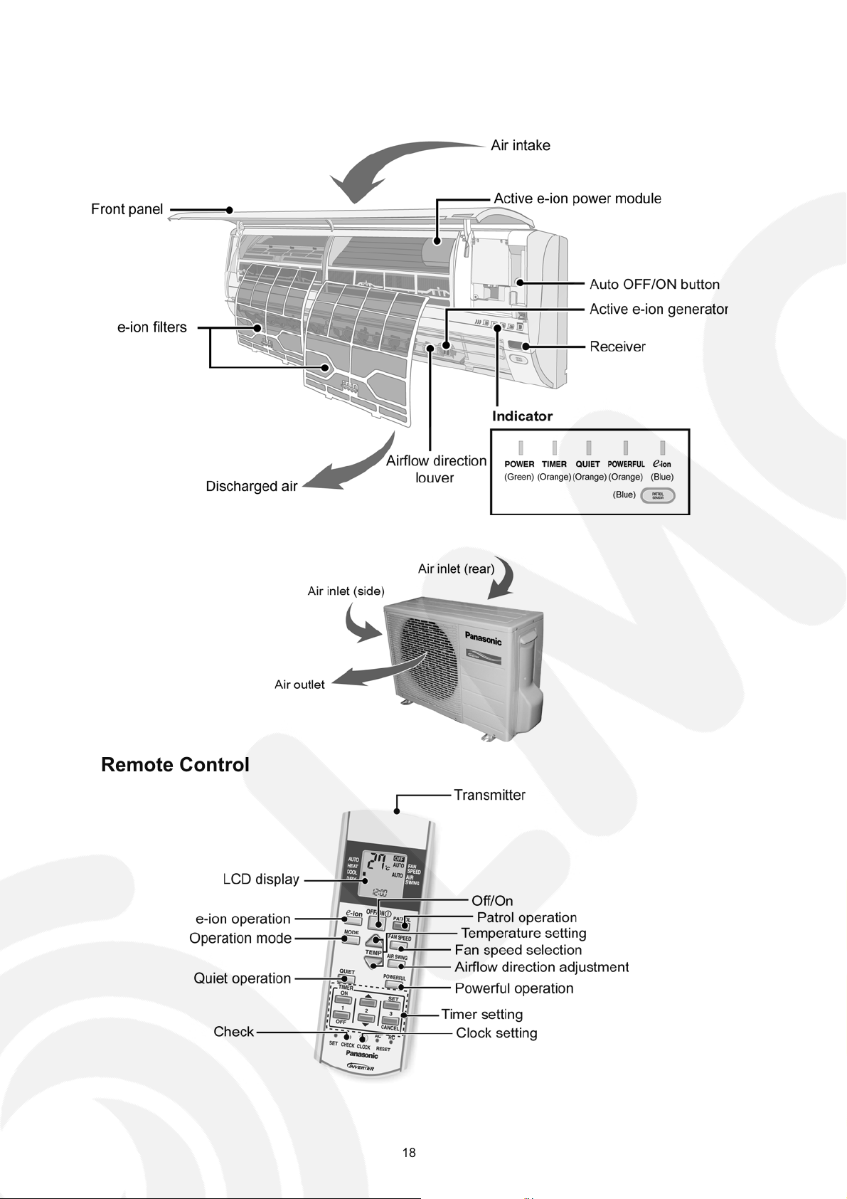
4 Location of Controls and Components
4.1. Indoor Unit
4.2. Outdoor Unit
4.3. Remote Control
18
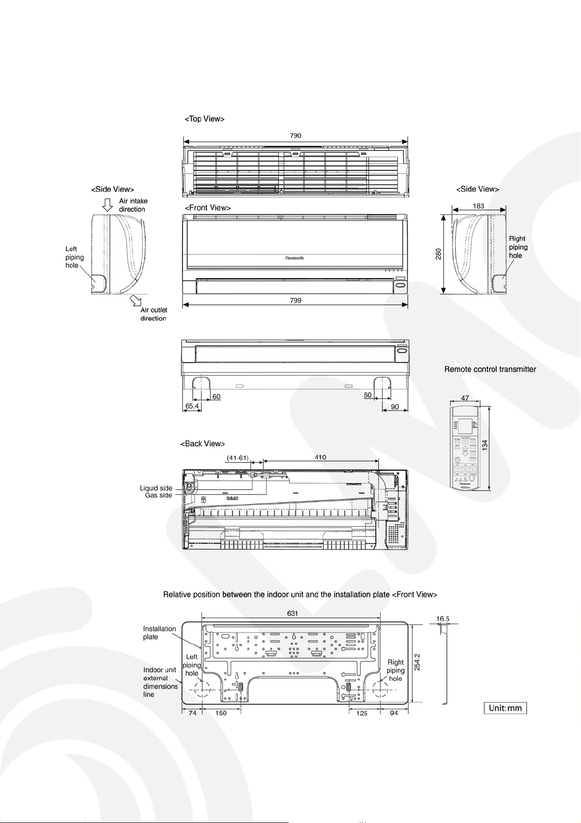
5 Dimensions
5.1. Indoor Unit
19
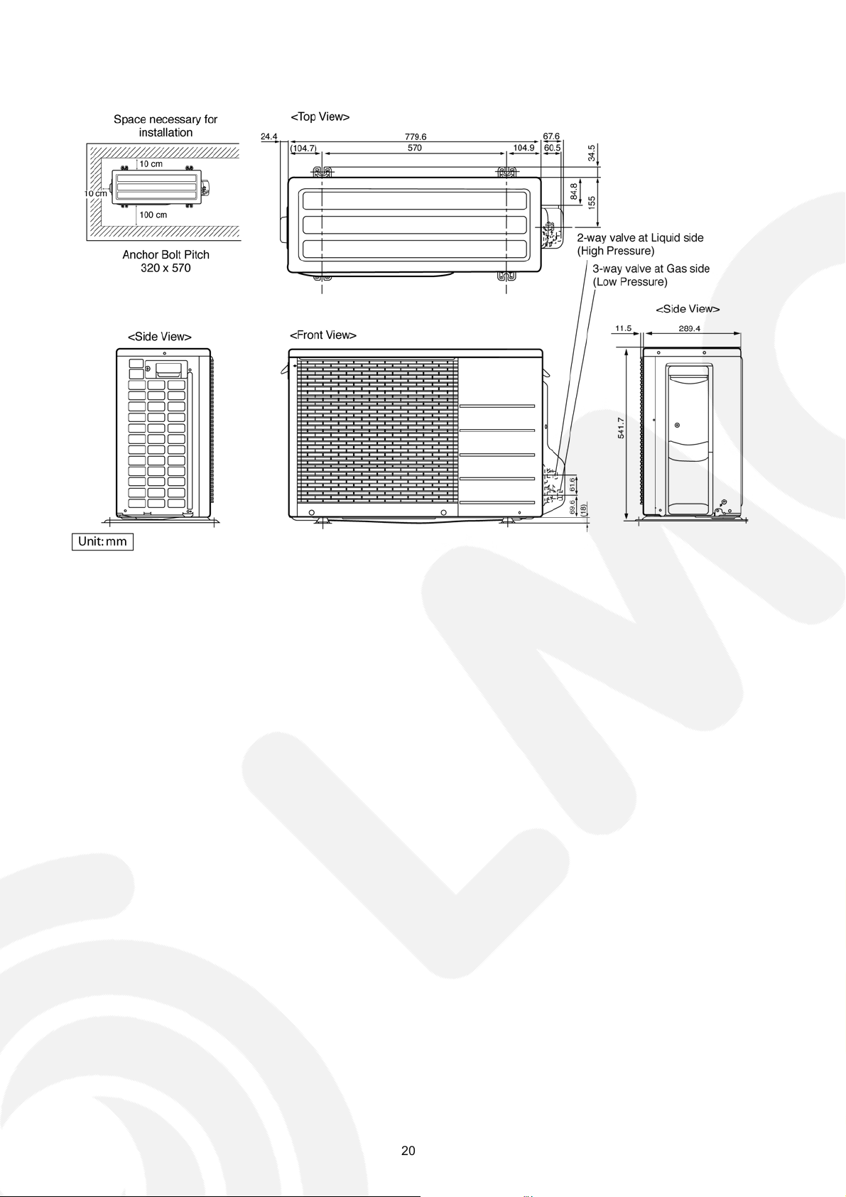
5.2. Outdoor Unit
20
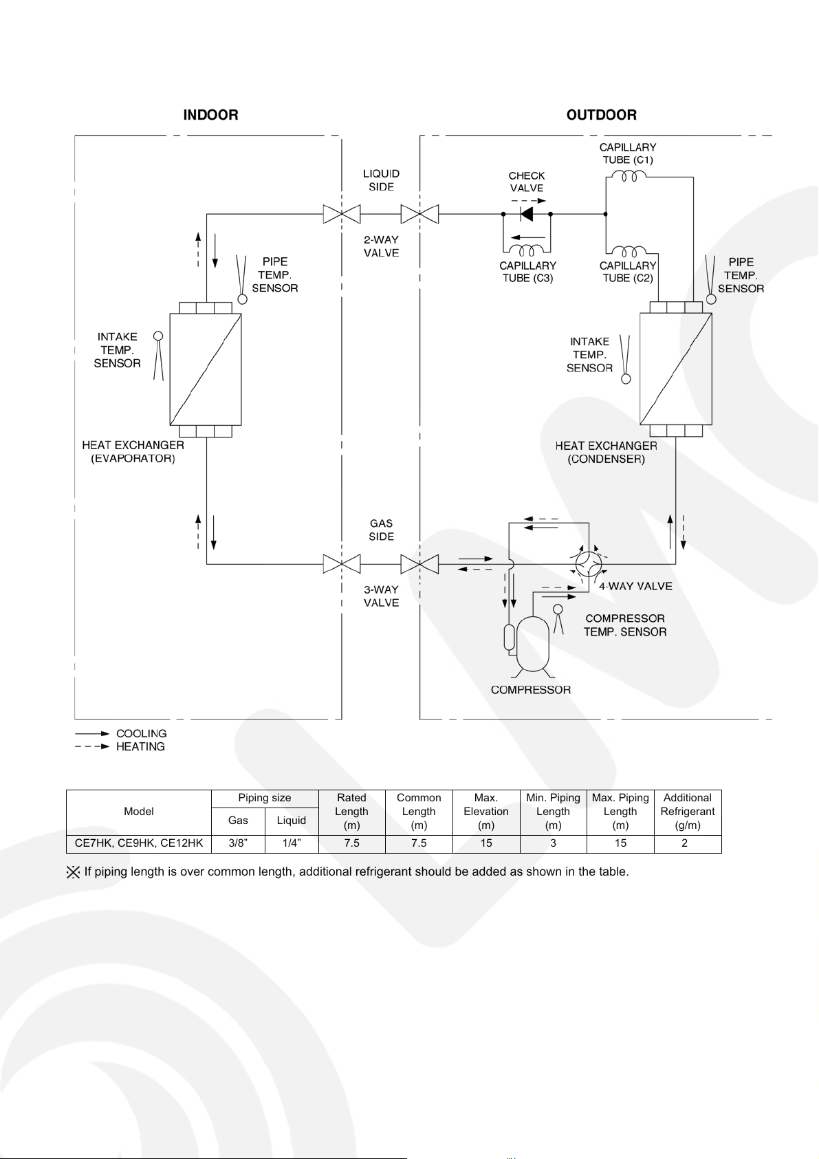
6 Refrigeration Cycle Diagram
Piping size Rated
Model
CE7HK, CE9HK, CE12HK 3/8” 1/4” 7.5 7.5 15 3 15 20
Gas Liquid
Length
(m)
Common
Length
(m)
Max.
Elevation
(m)
Min. Piping
Length
(m)
Max. Piping
Length
(m)
Additional
Refrigerant
(g/m)
If piping length is over common length, additional refrigerant should be added as shown in the table.
21
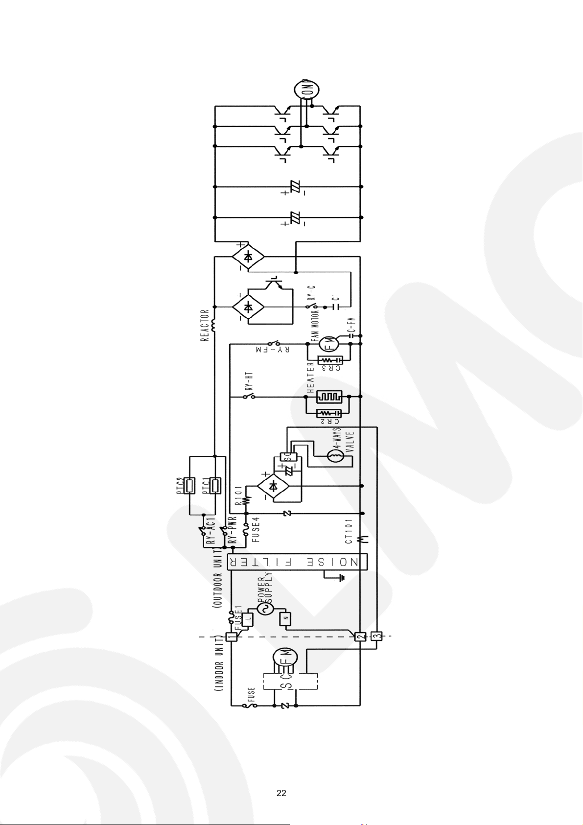
7 Block Diagram
22
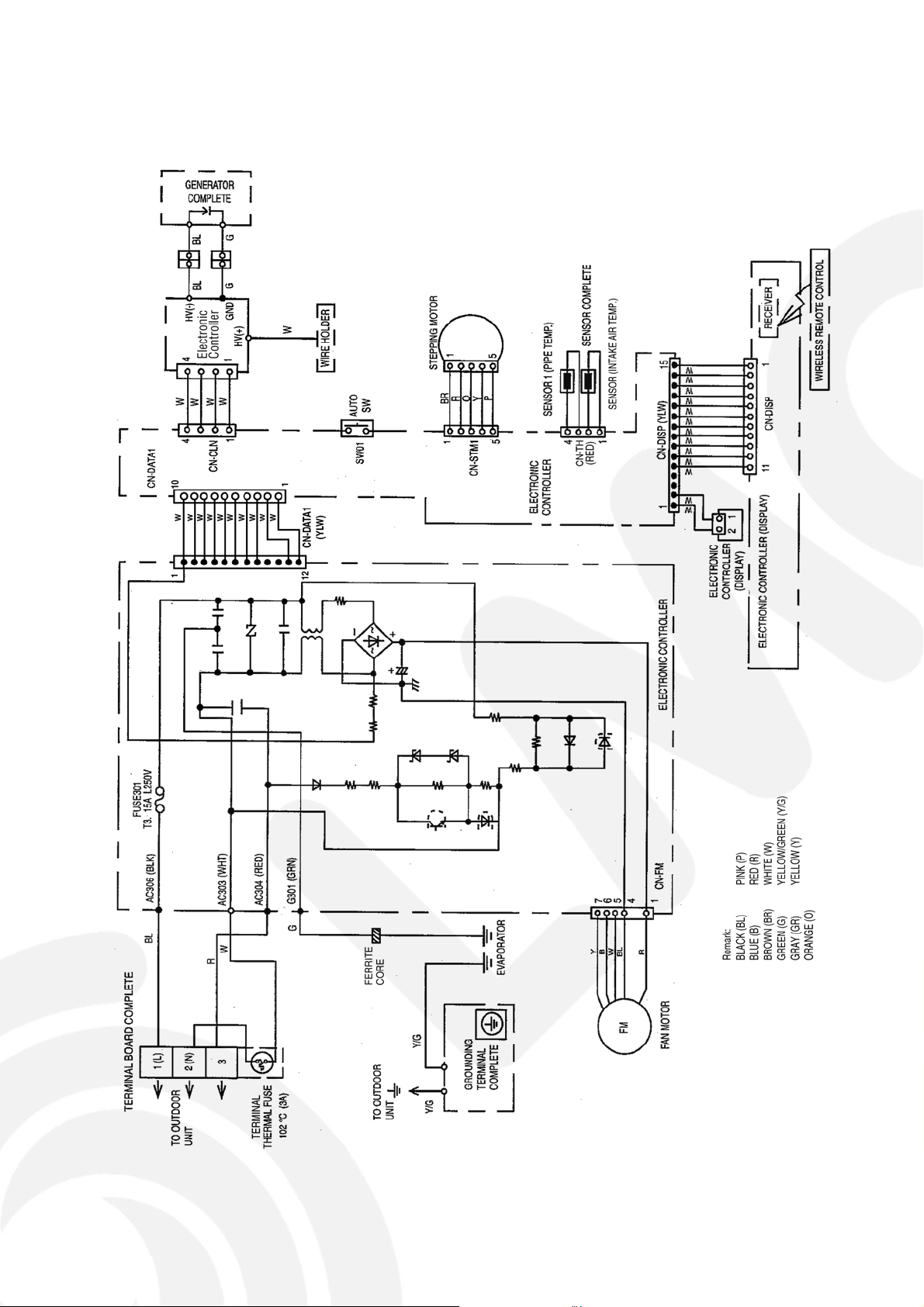
8 Wiring Connection Diagram
8.1. Indoor Unit
23
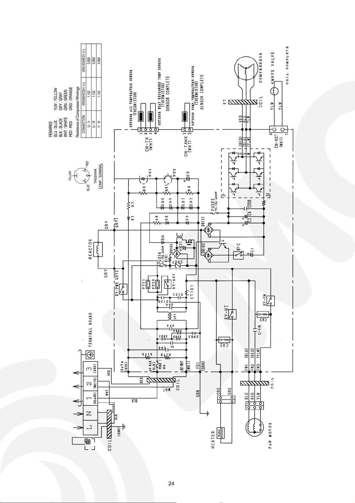
8.2. Outdoor Unit
24
 Loading...