

Panasonic CR-SRF100, CR-SRT100 User Manual
Sirius Satellite Radio
CR-SRF100
CR-SRT100
Operating Instructions
CR-SRF100 (SHOWN)

The contents of this manual are subject to change without notice and do not constitute a commitment on
the part of Matsushita Communication Industrial Corporation of USA (MCUSA). Every effort has been
made to ensure the accuracy of this document. However, due to ongoing product improvements and
revisions, MCUSA cannot guarantee the accuracy of printed material after the date of publication, nor can it
accept responsibility for errors or omissions. MCUSA will update and revise this document as necessary.
The software and hardware described in this document may be used or copied only in accordance with
the terms of the license pertaining to said software or hardware.
Copyright © 2002 by Matsushita Communication Industrial Corporation of USA (MCUSA). All rights reserved.
2
CR-SRF100/CR-SRT100

Table of Contents
1. ACRONYMS & ABBREVIATIONS . . . . . . . . . . . . . . . . . . . . . . . . . . . . . . . . . .4
2. BASIC FEATURES . . . . . . . . . . . . . . . . . . . . . . . . . . . . . . . . . . . . . . . . . . .4
3. WHAT IS SIRIUS SATELLITE RADIO (SSR) (SUMMARY DESCRIPTION) . . . . . . . .5
4. PRECAUTIONS . . . . . . . . . . . . . . . . . . . . . . . . . . . . . . . . . . . . . . . . . . . . .7
5. GETTING INITIAL SUBSCRIPTION FOR CHANNELS FROM SIRIUS . . . . . . . . . . . .8
6. SETUP MODE . . . . . . . . . . . . . . . . . . . . . . . . . . . . . . . . . . . . . . . . . . . . . .9
6.1. Enter & Exit Setup Mode . . . . . . . . . . . . . . . . . . . . . . . . . . . . . . . . .10
6.2. Select a Setup Item . . . . . . . . . . . . . . . . . . . . . . . . . . . . . . . . . . . .11
6.3. View the Sirius ID . . . . . . . . . . . . . . . . . . . . . . . . . . . . . . . . . . . . .12
6.4. Change the Display Brightness . . . . . . . . . . . . . . . . . . . . . . . . . . . . .13
6.5. Setup FM Modulator Frequency . . . . . . . . . . . . . . . . . . . . . . . . . . . .14
7. BASIC OPERATION . . . . . . . . . . . . . . . . . . . . . . . . . . . . . . . . . . . . . . . . . .17
7.1. General Descriptions . . . . . . . . . . . . . . . . . . . . . . . . . . . . . . . . . . .17
7.1.1. CDU Controls . . . . . . . . . . . . . . . . . . . . . . . . . . . . . . . . . . . .19
7.1.2. CDU Communication to the Operator . . . . . . . . . . . . . . . . . . . . .19
7.2. Start-Up/Shut-Down Modes . . . . . . . . . . . . . . . . . . . . . . . . . . . . . . .20
7.2.1. Start-Up (Turn On) . . . . . . . . . . . . . . . . . . . . . . . . . . . . . . . . .20
7.2.2. Shut-Down (Turn Off) . . . . . . . . . . . . . . . . . . . . . . . . . . . . . . .22
7.3. Standard Operations & Screen Display Format . . . . . . . . . . . . . . . . . .23
7.4. Category Mode . . . . . . . . . . . . . . . . . . . . . . . . . . . . . . . . . . . . . . .29
7.5. Channel Mode . . . . . . . . . . . . . . . . . . . . . . . . . . . . . . . . . . . . . . . .31
7.6. Preset Mode . . . . . . . . . . . . . . . . . . . . . . . . . . . . . . . . . . . . . . . . .32
8. SYSTEM COMPONENTS & SPECIFICATIONS . . . . . . . . . . . . . . . . . . . . . . . . .34
8.1. SSR Receiver … (CR-ZX0161Z) . . . . . . . . . . . . . . . . . . . . . . . . . . . .35
8.2. Control Display Unit (CDU) … (CY-CX0160Z) . . . . . . . . . . . . . . . . . . . .36
8.3. FM Modulator … (CY-ZX0160Z) . . . . . . . . . . . . . . . . . . . . . . . . . . . .37
8.4. Receiver Wiring Harness … (M2C457018) . . . . . . . . . . . . . . . . . . . . .38
8.5. Receiver Wiring Harness … (M2C457019) . . . . . . . . . . . . . . . . . . . . .39
9. DIAGRAMS & INSTALLATION . . . . . . . . . . . . . . . . . . . . . . . . . . . . . . . . . . .40
9.1. General System Diagrams . . . . . . . . . . . . . . . . . . . . . . . . . . . . . . . .40
9.2. General Connection Diagram . . . . . . . . . . . . . . . . . . . . . . . . . . . . . .42
9.3. Installation . . . . . . . . . . . . . . . . . . . . . . . . . . . . . . . . . . . . . . . . . .44
10. MAINTENANCE & TROUBLESHOOTING . . . . . . . . . . . . . . . . . . . . . . . . . . . .47
Notes . . . . . . . . . . . . . . . . . . . . . . . . . . . . . . . . . . . . . . . . . . . . . . . . . .50
CR-SRF100/CR-SRT100
3
WELCOME
S
EL
P
W
R
Panasonic welcomes you to their constantly growing family of electronic products owners. We endeavor to
give you the advantages of products with precise electronic and mechanical engineering, manufactured with
carefully selected components, and assembled by people who are proud of the reputation their work has
built for our company. We know this product will bring you many hours of enjoyment, and after you discover
the quality, value and reliability we have built into it, you too will be proud to be a member of our family.
1. Acronyms & Abbreviations
• CDU: Control Display Unit
• SEL: The “SELECT” button/knob.
• PDT: Program Descriptive Text
• SSR: Sirius Satellite Radio
• SDARS: Satellite Digital Audio Receiver System
2. Basic Features
4
CR-SRF100/CR-SRT100

Summary Description
Category 1
(ex: “Rock”)
-------Channel 1
Channel 2
Channel 4
Channel 6
Channel 11
Channel 13
Channel 26
Channel 45
Category 3
(ex: “Country”)
-------Channel 8
Channel 9
Channel 10
Channel 14
Channel 15
Channel 18
Channel 29
Channel 41
Category 2
(ex: “Jazz”)
-------Channel 3
Channel 5
Channel 7
Channel 12
Channel 16
Channel 33
Channel 58
...
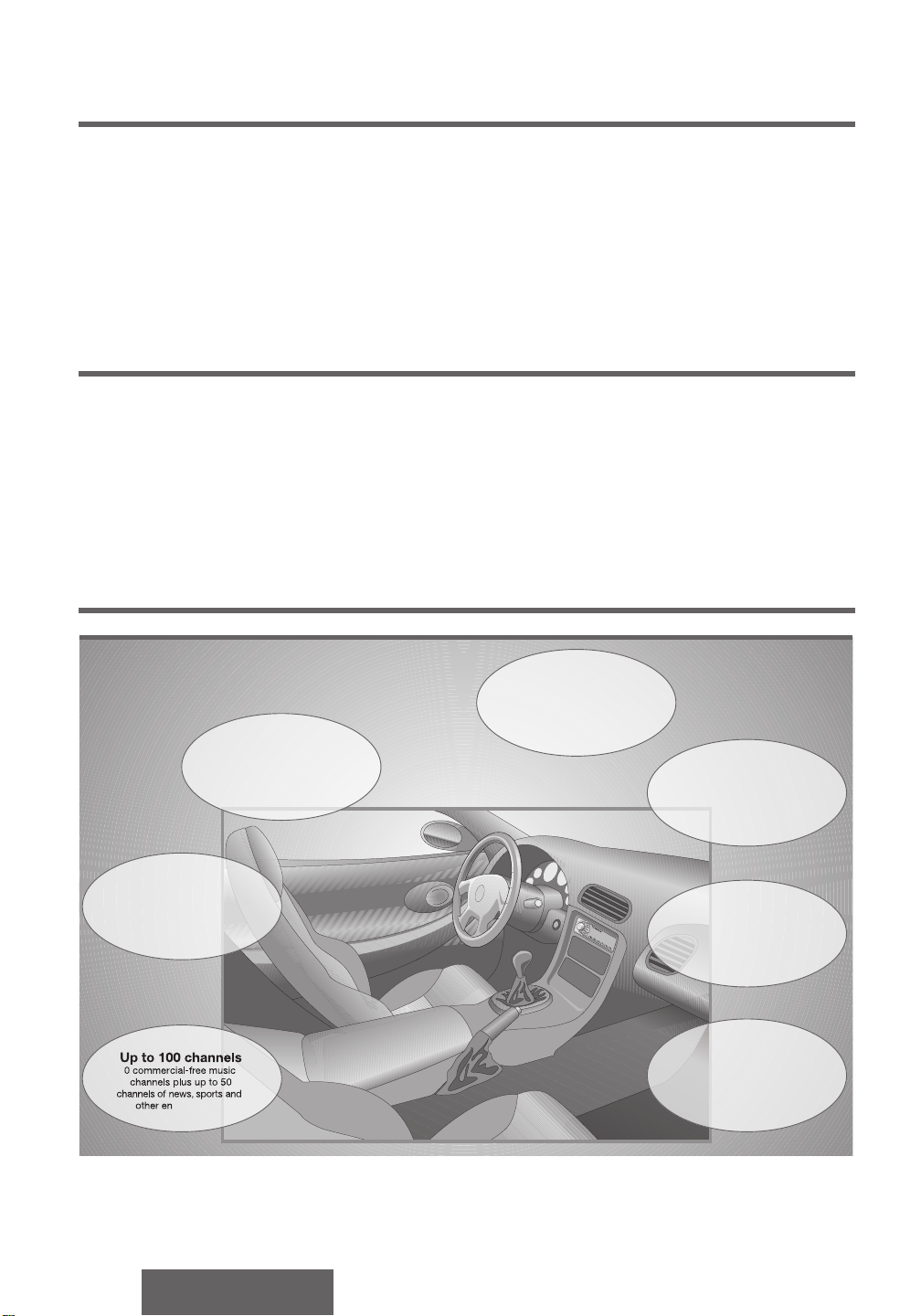
The Service
100 channels of music, news, sport, and other entertainment. 60 channels of 100% commercial-free music.
All broadcast directly to your vehicle, anywhere in the continental United States.
The Programming
There are no painfully repetitive play lists. Music is hosted live by Master Music Programmers and on-air
personalities who are true experts in their fields. When they do speak, it’s to give you some information
regarding the music being played.
Channel to Category Organization
Channel and Category organization can be illustrated as:
Displayable Information
The different types of displayable information are:
• Category: Name of category.
• Channel: Name of channel and channel number.
• Program / Song: Program Descriptive Text (PDT) data … such as:
- Current Artist Name
- Current Album Name
- Current Song Title
- Record label for current song
- “other current information”
Primary Components
There are 5 basic components to the SSR system:
1. SSR Receiver
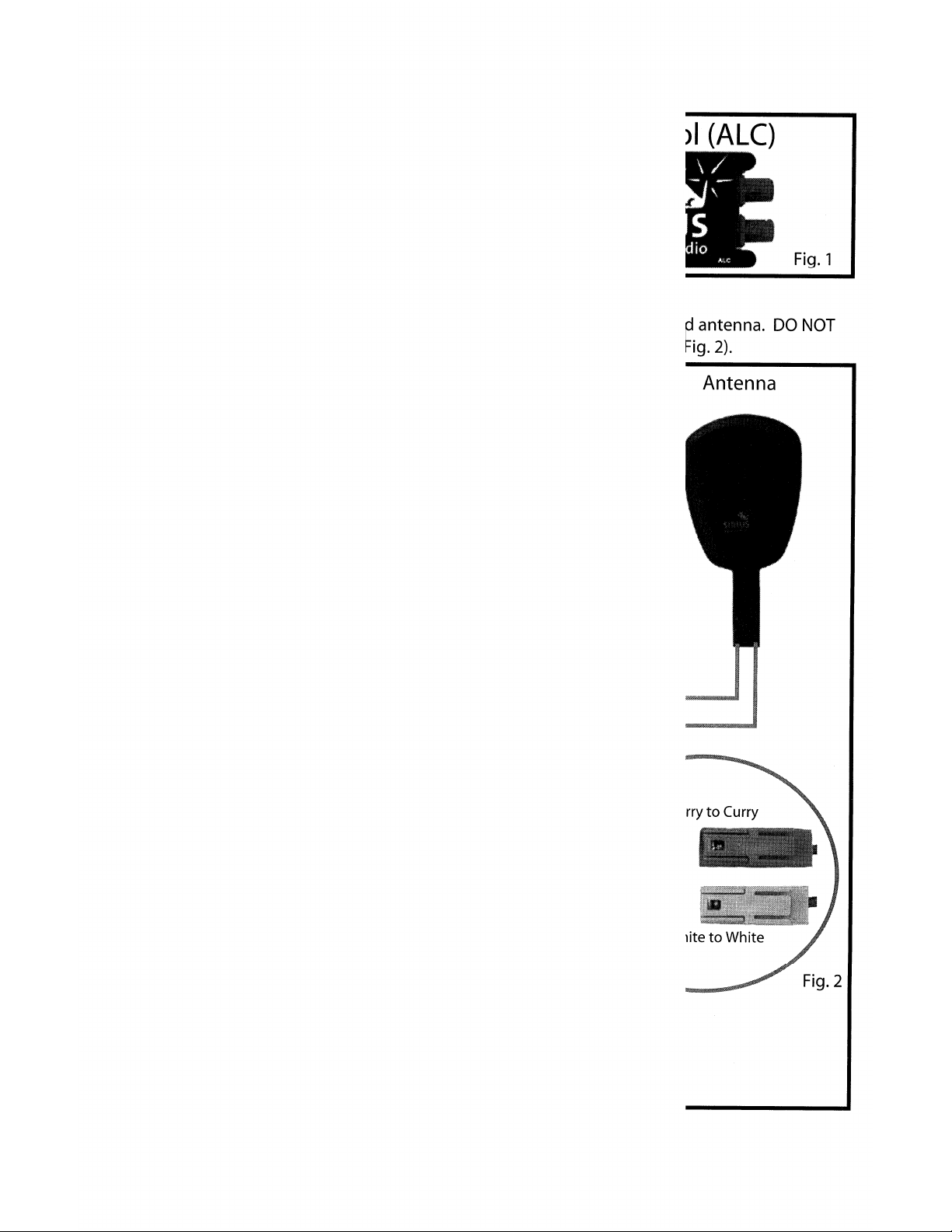
2. Antenna (Sold Separately)
3. Controller / Display Unit (Included in CR-SRF100)
4. FM Modulator (Included in CR-SRF100)
5. Receiver Wiring Harness
CR-SRF100/CR-SRT100
5
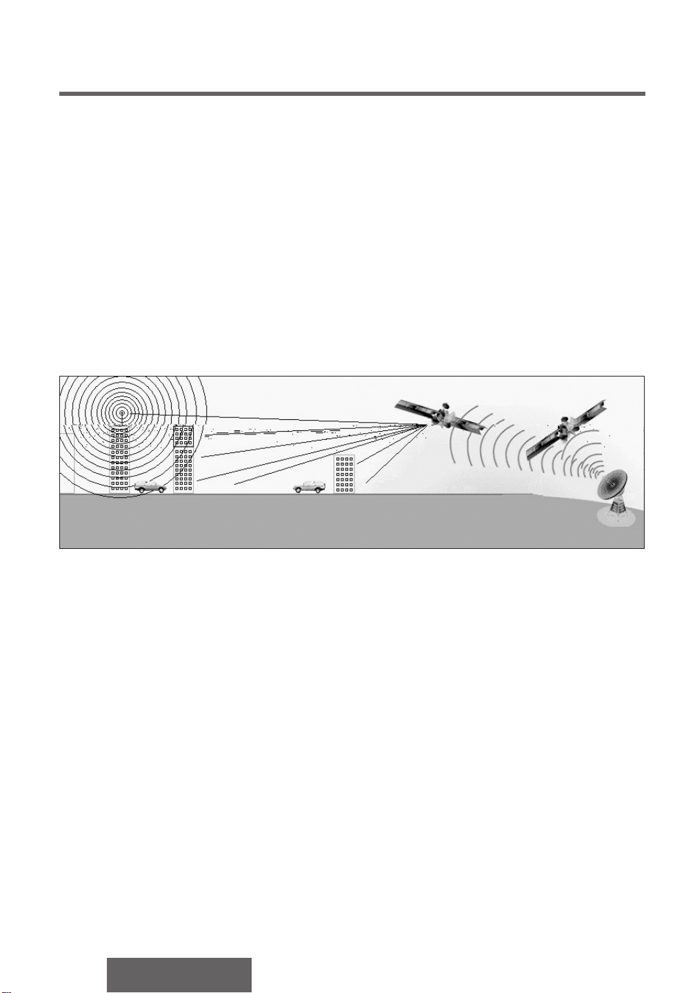
The Technology
The Sirius Satellite Radio service begins at the national broadcast studios in New York City, where the
programs are created. They are then beamed to the three orbiting satellites and ground repeaters, which
then send them to the receiver in your vehicle. This signal is maximized by placing the satellites in orbits
directly above the United States rather than geostationary orbits over the equator. The result is the most
optimal signal strength.
This system is broadcast in the S-Band and has a frequency range of 2319.75MHz to 2332.75MHz.
A Note About Reception
Satellite signals may be completely blocked by buildings, overpasses, or other structures and they
operate best with a “clear line of sight.” For this reason, terrestial repeaters are placed in dense urban
areas to supplement the satellite coverage area.
In the illustration above (not drawn to scale), the satellite signal is prevented from directly reaching either
vehicle. However, the vehicle on the left is within range of a terrestial repeater and therefore can recieve
broadcast until it emerges from the “electronic shadow” of the building.
Not: the Sirius broadcast satellites orbit almostdirectly overhead so their “shadow” is very small.
However, the satellite’s precise location in the sky changes hour by hour and the corresponding “shadow”
will change as well.
Momentary interruption of the satellite signal is protected by a four-second audio memory in the receiver.
Therefore, if the signal blockage exists for less than four seconds, there will be no interruption of the audio.
The combination of overhead placement, terrestial repeaters, and the four-second audio memory should
provide coast-to coast coverage with few interruptions.
6
CR-SRF100/CR-SRT100

4. Precautions
CAUTIONS
• This product is designed to operate off a 12 volt, negative ground battery system.
• To prevent damage to the unit, be sure to follow the connection diagram in section 9.2.
• Do not insert the power connector into the unit until the wiring is completed.
• Be sure to insulate any exposed wires from a possible short-circuit to the car chassis.
Bundle all cables and keep cable terminals free from touching any metal parts.
• Noted that if your car has a driving computer or navigation computer, disconnecting the
battery cables may cause the contents of memory for these computer to be lost.
MAINTENANCE
Your product is designed and manufactured to ensure the minimum of maintenance. Use a soft
cloth for routine exterior cleaning. Never use benzine or other solvents.
WHEN SOMETHING DOESN’T WORK
Check the Maintenance and Troubleshooting on pages 47 through 50 for possible causes and the
problem you might be experiencing. Some simple checks or minor adjustment may eliminate the
problem.
FOR PRODUCT SERVICING
If you experience any operational difficulties, or require a repair, please refer to the original
installer or your supplying dealer for assistance. Otherwise, call Panasonic Customer Service
1-800-211-PANA (7262) for assistance.
REPLACING THE FUSE
Use fuses of the same specified rating 3A for yellow wire and 0.5A for red wire. Using different
substitutes or fuses with higher ratings, or connecting the unit directly without a fuse, could cause
fire or damage to the receiver system. If the replacement fuse fails, contact the Panasonic Customer Service
1-800-211-PANA for assistance
CAR WASHING
To avoid electrical shorts which may cause fire, or other damage, do not expose this product to water or
excessive moisture.
PRODUCT & SIRIUS SERIAL ID NUMBERS
It is especially important to retain the unit’s product serial number and the electronic Sirius Identification
Number for service activation and potential future service changes.
CR-SRF100/CR-SRT100
7
5. Getting Initial Subscription
For Channels From Sirius
If your system has been powered up and a subscription for satellite
services has already been done, then SKIP this section...you are ready to
finish setting up the system or operate it.
Only continue with this section after the system is installed in the vehicle and the battery is connected.
There are 3 basic steps:
1. Turn the power on by pressing the [SEL] knob/button.
(the unit’s Sirius ID number should be displayed)
(if the ID number is not displayed, skip this section … already subscribed!)
Note: If this is the first time the radio has been powered on, please leave the unit powered up for
approximately 5 minutes without operating the controls. There is transmission-specific information which
must be loaded into the receiver from the satellite signal.
2. Record the receiver’s product serial number (printed on a label on the receiver) and Sirius ID number
from the display. (See section 6.1 for information on displaying the Sirius ID.)
8
CR-SRF100/CR-SRT100

You are now ready to activate your service. You have one of two options:
1) Visit the website at: http://www.siriusradio.com
Click on the “JOIN” section and follow some simple directions.
2) Call toll-free 1-888-539-SIRIUS (7474) and one of the customer care representatives will take the
necessary pieces of information and walk you through the activation process.
Please have the following ready when attempting to activate your service:
- Sirius ID number
- Valid credit card information (number & expiration).
Note: After your unit is activated, you may need to rotate the SEL knob to begin playing audio.
6. Setup Mode
Setup mode is used to set the various radio system parameters and display information. It is not expected
to be used often; therefore a dedicated setup mode button does not exist.
LIST OF SETUP OPERATIONS IDENTIFIED
The following operations are available to the user:
1. Entering & Exiting Setup Mode
2. Selecting a Setup Item
3. View the Electronic Sirius ID
4. Change the display brightness
5. Setup the FM modulator frequency
CR-SRF100/CR-SRT100
9
6.1. Enter & Exit Setup Mode
ENTERING SETUP MODE
A user enters setup mode by pressing the [1] and [6] buttons simultaneously. The system then displays the
setup mode screen, with viewing the Sirius ID as the first setup item choice.
EXITING FROM SETUP MODE
You may exit setup mode by entering a different mode (press and release [CHANNEL] or [CATEGORY] or
[PRESET] buttons).
10
CR-SRF100/CR-SRT100
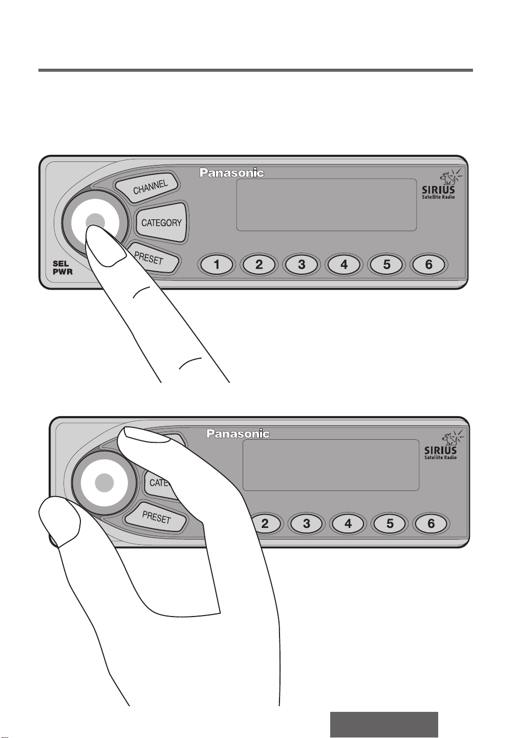
6.2. Select a Setup Item
SEL
PWR
When in setup mode, the [SEL] knob is used to navigate to the different setup screens. Pressing and
releasing the [SEL] knob will move to the next setup item.
Where appropriate, rotating the [SEL] knob will move to the next selection within the current setup item.
CR-SRF100/CR-SRT100
11
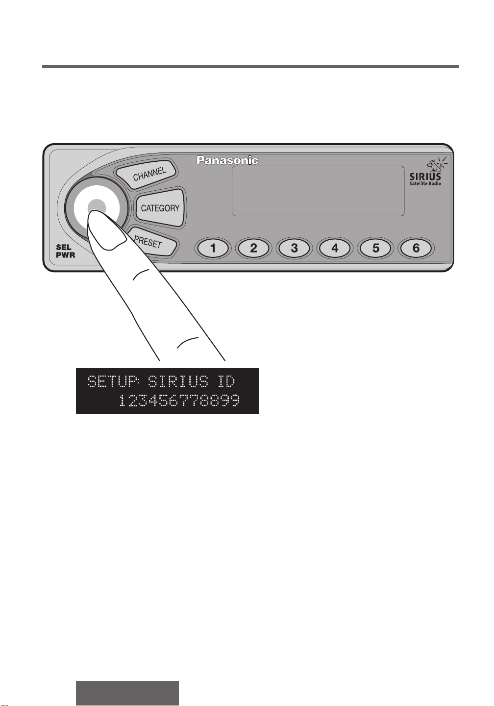
6.3. View the Sirius ID
The Sirius ID Number is displayed on the CDU when setup mode is entered [SECTION 6.1]. Pressing the
[SEL] button moves to the next setup item. Rotating the [SEL] button has no effect.
12
CR-SRF100/CR-SRT100
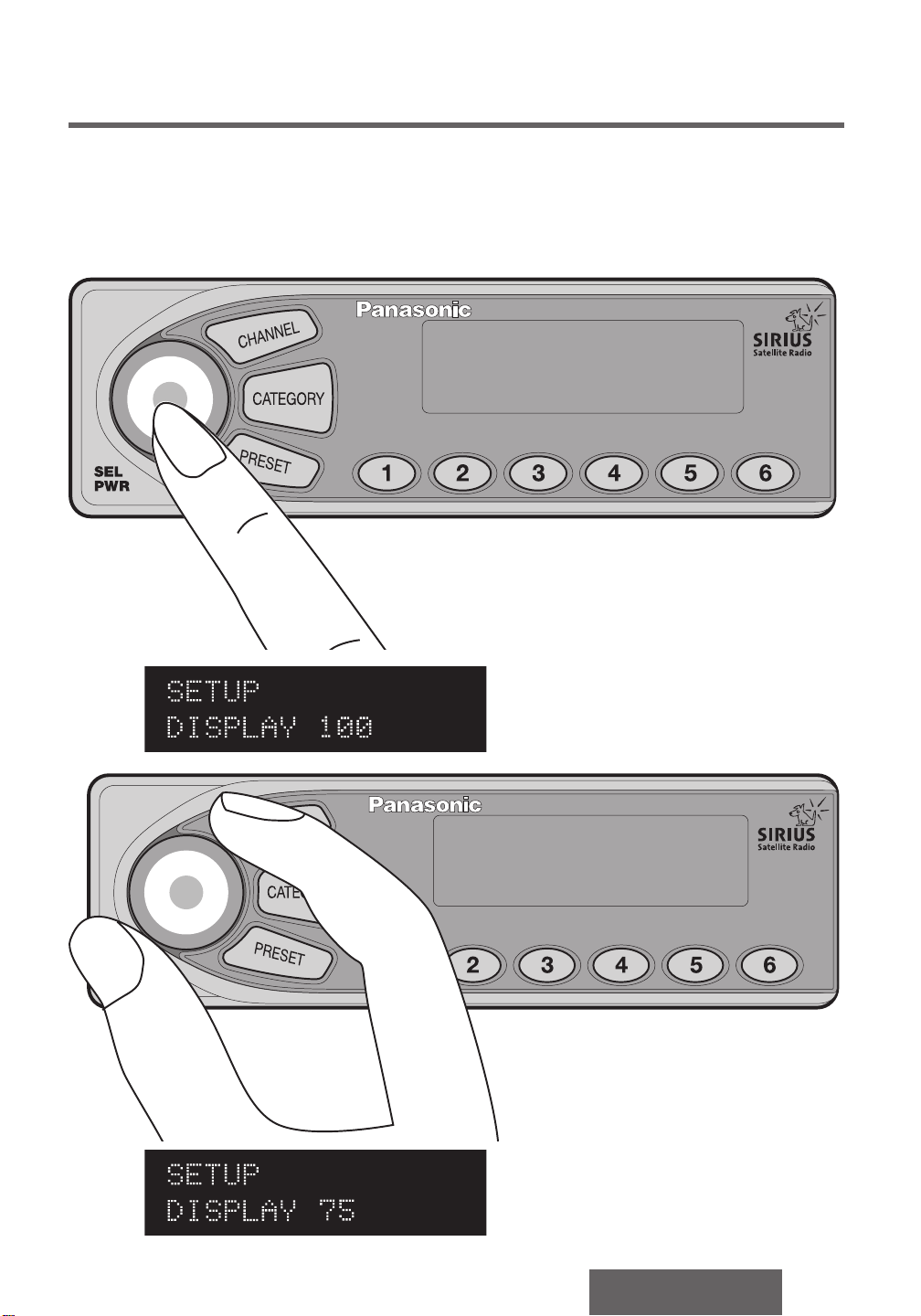
6.4. Change the Display Brightness
SEL
PWR
ENTER SETUP MODE [SECTION 6.1]
When the Adjust Brightness setup option is selected by pressing the [SEL] button, the brightness of the
character display is changed. You may select between 4 brightness levels (25% [dimmest], 50%, 75%,
100% [brightest]) by rotating the [SEL] knob. Pressing the [SEL] button selects the brightness level
currently displayed and moves the user to the next setup item.
%
%
CR-SRF100/CR-SRT100
13
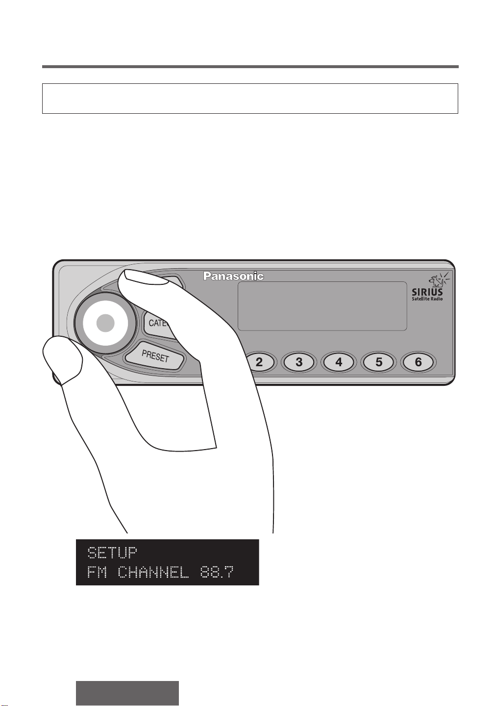
6.5. Setup FM Modulator Frequency
SEL
PWR
Please disregard if an FM modulator is not in your system.
The Sirius receiver has the capability to send audio output to an FM radio by means of a hardware FM
modulator. This option is enabled through the setup mode, and the FM frequency is set up as well.
Below is a table of the 11 FM Modulator settings available: the “OFF” state and the 10 frequency settings.
The CDU displays the frequency (MHz) or OFF when in this mode.
When the [SEL] knob is rotated, the system increments or decrements the modulator frequency according
to the table. It is recommended that an unused frequency currently with no FM broadcast be used for the
FM Modulator frequency. Pressing the [SEL] button selects the modulator frequency currently displayed
and moves the user to the next setup item.
14
CR-SRF100/CR-SRT100

Index Frequency
0 OFF
1 88.7 MHz
2 88.9 MHz
3 89.1 MHz
4 89.3 MHz
5 89.5 MHz
6 89.7 MHz
7 89.9 MHz
8 90.1 MHz
9 90.3 MHz
10 90.5 MHz
If you try to use the Sirius Satellite Radio system with an FM modulator and you don’t have the radio tuned
to the correct frequency, you might only hear static. The radio must be on the same FM station as the SSR
system is set.
For convenience, we recommend you assign the appropriate FM modulator frequency to one of the
preset buttons on your FM radio.
CR-SRF100/CR-SRT100
15
 Loading...